

verilog

산업 제조
멀티플렉서 또는 mux 요컨대 선택 신호를 기반으로 N 입력 중 하나에서 출력으로 데이터를 전송하는 디지털 요소입니다. 아래에 표시된 경우는 N이 4인 경우입니다. 예를 들어, 4비트 멀티플렉서는 선택 신호를 사용하여 각 입력을 출력으로 전송할 수 있는 4비트 각각의 N 입력을 갖습니다.
<노스크립트>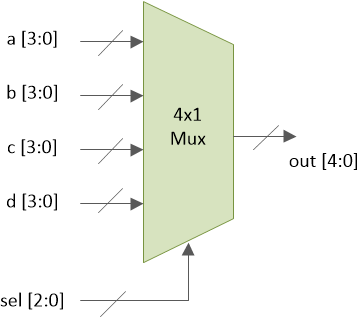
sel은 2비트 입력이며 4개의 값을 가질 수 있습니다. 선택 라인의 각 값은 입력 중 하나를 출력 핀 아웃으로 보낼 수 있도록 합니다.
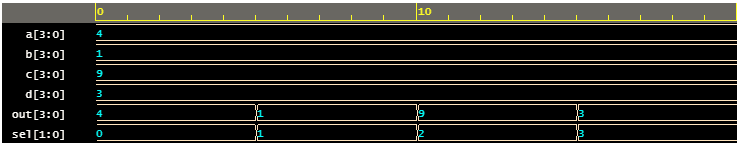
	sel     a     b     c     d     out
	 0     3    7     1     9    3
	 1      3    7    1     9    7
	 2      3     7    1    9    1
	 3      3     7     1    9   9
4x1 멀티플렉서는 여러 가지 방법으로 구현할 수 있으며 여기에서 가장 일반적인 두 가지 방법을 볼 수 있습니다.
assign 사용 성명서case 사용 성명서assign 사용 성명서
module mux_4to1_assign ( input [3:0] a,                 // 4-bit input called a
                         input [3:0] b,                 // 4-bit input called b
                         input [3:0] c,                 // 4-bit input called c
                         input [3:0] d,                 // 4-bit input called d
                         input [1:0] sel,               // input sel used to select between a,b,c,d
                         output [3:0] out);             // 4-bit output based on input sel

   // When sel[1] is 0, (sel[0]? b:a) is selected and when sel[1] is 1, (sel[0] ? d:c) is taken
   // When sel[0] is 0, a is sent to output, else b and when sel[0] is 0, c is sent to output, else d
   assign out = sel[1] ? (sel[0] ? d : c) : (sel[0] ? b : a);

endmodule
mux_4x1_assign이라는 모듈 4비트 데이터 입력 4개, 2비트 선택 입력 1개, 4비트 데이터 출력 1개가 있습니다. 멀티플렉서는 assign 성명서.
case 사용 성명서
신호 출력은 reg로 선언됩니다. 절차적에서 사용되기 때문에 유형 always과 같은 블록 .
module mux_4to1_case ( input [3:0] a,                 // 4-bit input called a
                       input [3:0] b,                 // 4-bit input called b
                       input [3:0] c,                 // 4-bit input called c
                       input [3:0] d,                 // 4-bit input called d
                       input [1:0] sel,               // input sel used to select between a,b,c,d
                       output reg [3:0] out);         // 4-bit output based on input sel

   // This always block gets executed whenever a/b/c/d/sel changes value
   // When that happens, based on value in sel, output is assigned to either a/b/c/d
   always @ (a or b or c or d or sel) begin
      case (sel)
         2'b00 : out <= a;
         2'b01 : out <= b;
         2'b10 : out <= c;
         2'b11 : out <= d;
      endcase
   end
endmodule
mux_4x1_case라는 모듈 4비트 데이터 입력 4개, 2비트 선택 입력 1개, 4비트 데이터 출력 1개가 있습니다. 멀티플렉서는 case 성명서.
두 가지 유형의 멀티플렉서 모델은 아래 이미지와 같이 동일한 하드웨어로 합성됩니다.
<노스크립트>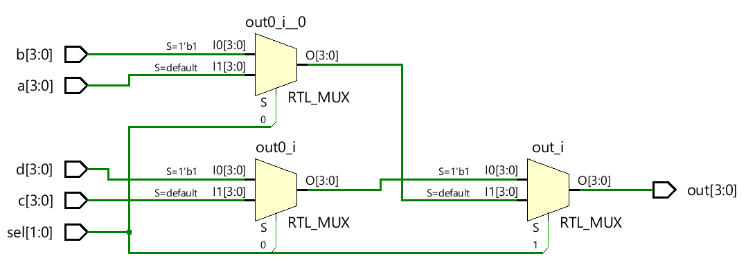
module tb_4to1_mux;

   // Declare internal reg variables to drive design inputs
   // Declare wire signals to collect design output
   // Declare other internal variables used in testbench
   reg [3:0] a;
   reg [3:0] b;
   reg [3:0] c;
   reg [3:0] d;
   wire [3:0] out;
   reg [1:0] sel;
   integer i;

   // Instantiate one of the designs, in this case, we have used the design with case statement
   // Connect testbench variables declared above with those in the design
   mux_4to1_case  mux0 (   .a (a),
                           .b (b),
                           .c (c),
                           .d (d),
                           .sel (sel),
                           .out (out));

   // This initial block is the stimulus
   initial begin
      // Launch a monitor in background to display values to log whenever a/b/c/d/sel/out changes
      $monitor ("[%0t] sel=0x%0h a=0x%0h b=0x%0h c=0x%0h d=0x%0h out=0x%0h", $time, sel, a, b, c, d, out);

   	  // 1. At time 0, drive random values to a/b/c/d and keep sel = 0
      sel <= 0;
      a <= $random;
      b <= $random;
      c <= $random;
      d <= $random;

      // 2. Change the value of sel after every 5ns
      for (i = 1; i < 4; i=i+1) begin
         #5 sel <= i;
      end

      // 3. After Step2 is over, wait for 5ns and finish simulation
      #5 $finish;
   end
endmodule
시뮬레이션 로그 ncsim> run [0] sel=0x0 a=0x4 b=0x1 c=0x9 d=0x3 out=0x4 [5] sel=0x1 a=0x4 b=0x1 c=0x9 d=0x3 out=0x1 [10] sel=0x2 a=0x4 b=0x1 c=0x9 d=0x3 out=0x9 [15] sel=0x3 a=0x4 b=0x1 c=0x9 d=0x3 out=0x3 Simulation complete via $finish(1) at time 20 NS + 0<노스크립트>
verilog
Verilog는 하드웨어 설명 언어이며 설계자가 RTL 설계를 시뮬레이션하여 논리 게이트로 변환할 필요가 없습니다. 시뮬레이션이 필요한 이유는 무엇입니까? 시뮬레이션은 RTL 코드가 의도한 대로 동작하는지 확인하기 위해 다른 시간에 다른 입력 자극을 설계에 적용하는 기술입니다. 기본적으로 시뮬레이션은 설계의 견고성을 검증하기 위해 잘 따라야 하는 기술입니다. 또한 가공된 칩이 실제 세계에서 사용되는 방식과 다양한 입력에 반응하는 방식과 유사합니다. 예를 들어, 위의 디자인은 출력 pe 보여진 바와 같이. 시뮬레이션을 통해
먹스 또는 멀티플렉서란 무엇입니까? 멀티플렉서 또는 mux 요컨대 선택 신호를 기반으로 N 입력 중 하나에서 출력으로 데이터를 전송하는 디지털 요소입니다. 아래에 표시된 경우는 N이 4인 경우입니다. 예를 들어, 4비트 멀티플렉서는 선택 신호를 사용하여 각 입력을 출력으로 전송할 수 있는 4비트 각각의 N 입력을 갖습니다. sel은 2비트 입력이며 4개의 값을 가질 수 있습니다. 선택 라인의 각 값은 입력 중 하나를 출력 핀 아웃으로 보낼 수 있도록 합니다. sel a b c d out