

제조공정

산업 제조
 |
| × | 1 | |||
 |
| × | 1 | |||
| × | 1 | ||||
| × | 4 | ||||
| × | 4 | ||||
| × | 4 | ||||
| × | 4 | ||||
| × | 2 | ||||
| × | 2 | ||||
| × | 2 | ||||
| × | 2 | ||||
| × | 2 | ||||
| × | 4 | ||||
| × | 4 | ||||
| × | 8 | ||||
| × | 2 | ||||
| × | 1 | ||||
| × | 1 | ||||
| × | 1 | ||||
| × | 1 | ||||
| × | 1 | ||||
| × | 1 | ||||
| × | 1 | ||||
| × | 1 |
 |
|
 |
| |||
| ||||
 |
|
프로젝트 개요
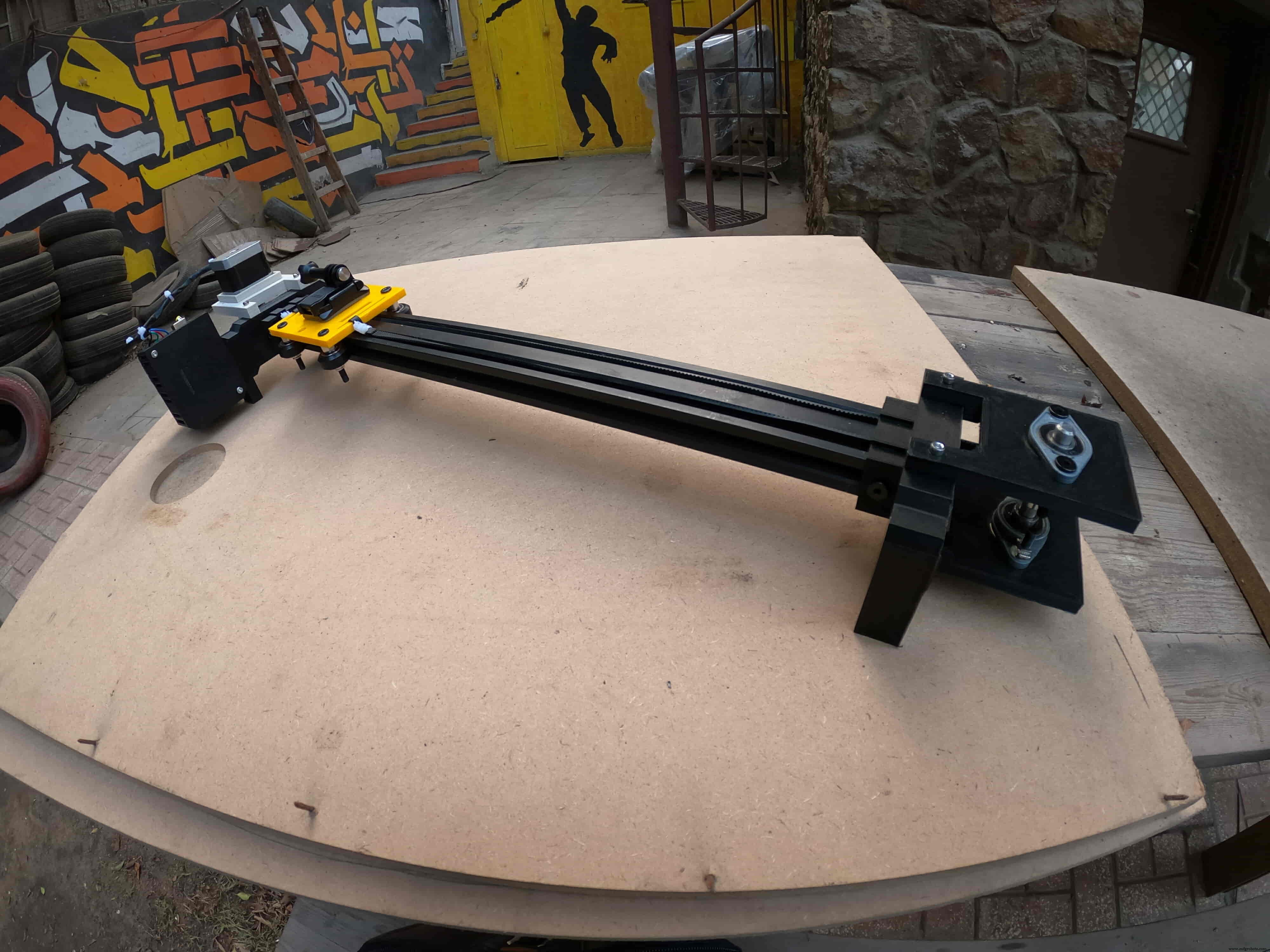
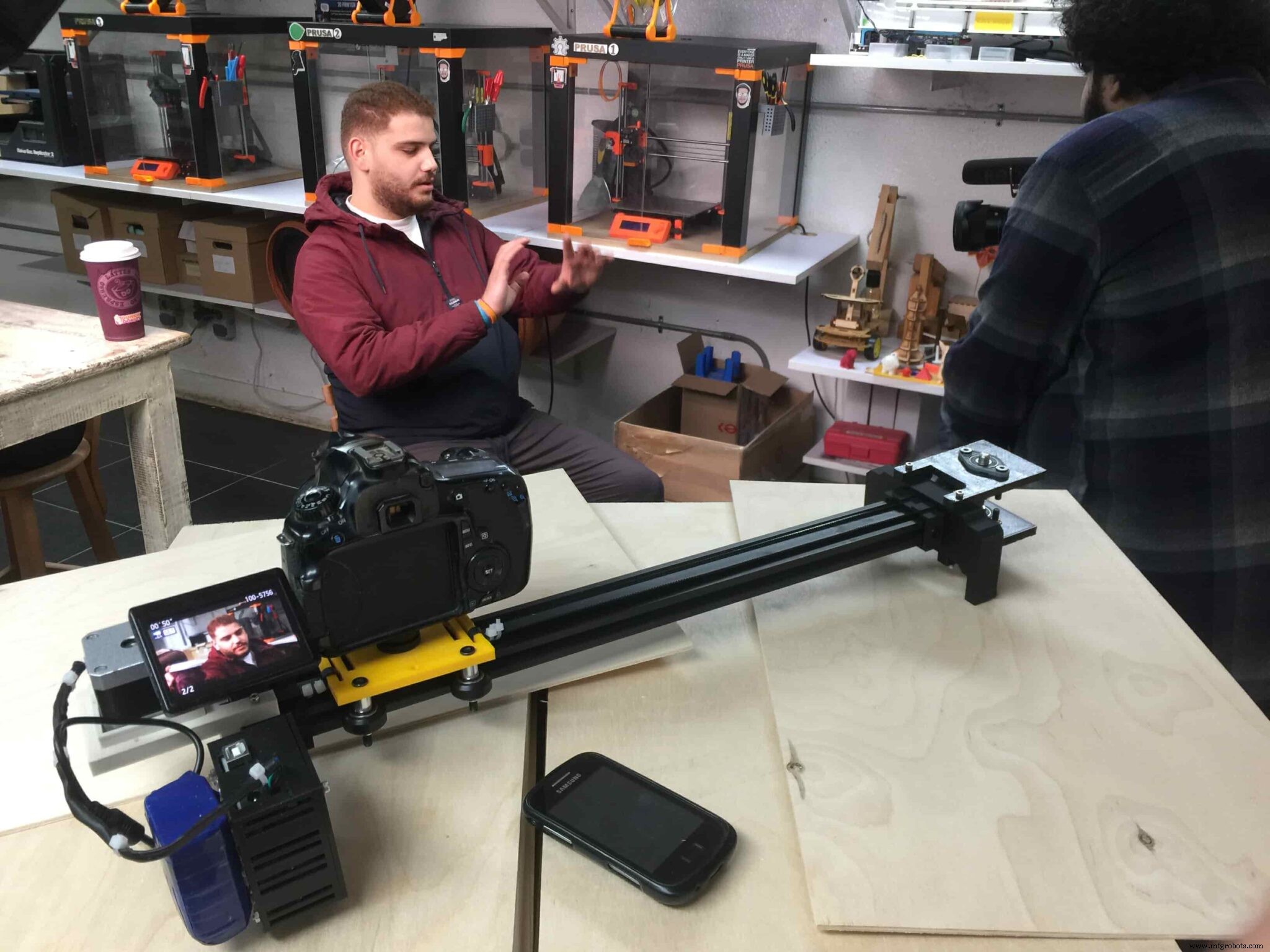
임의의 취미 비디오를 촬영하는 것을 좋아하는 사람에게는 전동 카메라 슬라이더를 구입하는 것이 어떻게 든 비용이 많이 듭니다. 그래서, 나는 내 자신을 구축했습니다. 이 튜토리얼에서는 블루투스 제어 전동 카메라 슬라이더를 만들기 위한 각 단계를 살펴보겠습니다.
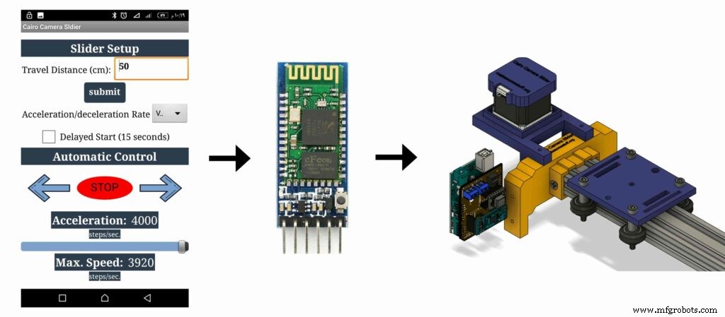
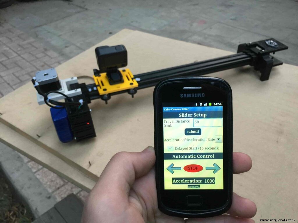
오늘 우리는 맞춤형 안드로이드 모바일 앱에서 블루투스를 통해 무선으로 제어할 수 있는 전동 카메라 슬라이더를 만들 것입니다. 저는 슬라이더 이동 속도, 이동 거리, 가속/감속 속도 등과 같은 많은 것을 제어할 수 있는 기능을 제공하는 앱을 만들기 위해 "MIT 앱 발명가" 도구를 사용했습니다. 모바일 앱은 매우 강력하며 앱 내에서 사용 중인 카메라 슬라이더 길이를 설정할 수 있습니다. 즉, 앱에 대해 걱정할 필요 없이 최대 10미터 길이의 실제 카메라 슬라이더를 자유롭게 만들 수 있습니다.
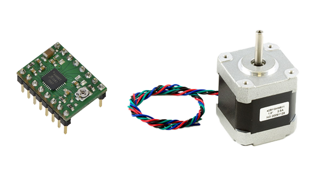
NEMA17 스테퍼 모터를 액추에이터로 사용하여 카메라 슬라이더를 이동하는 데 필요한 단계 수를 제어할 수 있습니다. Arduino 보드를 사용하여 스테퍼 모터를 제어하려면 Arduino 보드에서 명령을 가져와 스테퍼 모터가 이해할 수 있는 언어로 번역하는 번역기가 필요합니다. 여기에 A4988 Pololu 스테퍼 모터 드라이버 역할이 있습니다. 이 역할은 5가지 다른 마이크로스텝 분해능(1/16 단계까지)을 제공하여 최대의 이동 정확도와 부드러운 움직임을 달성합니다.
이 프로젝트는 fablab/makerspace/hackerspace를 염두에 두고 제작 가능성을 염두에 두고 설계되었습니다.
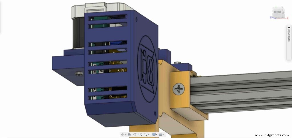
CAD 및 3D 모델링
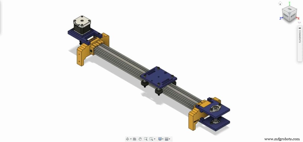
우리는 Fusion360을 사용하여 카메라 슬라이더를 설계했으며, 거주 지역에 관계없이 거의 모든 온라인 또는 오프라인 매장에서 쉽게 구입할 수 있는 매우 잘 알려져 있고 찾기 쉬운 기계 구성 요소를 사용하기로 결정했습니다.
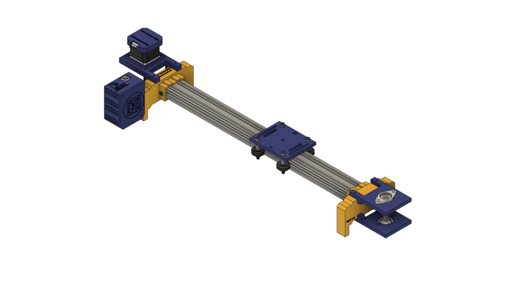
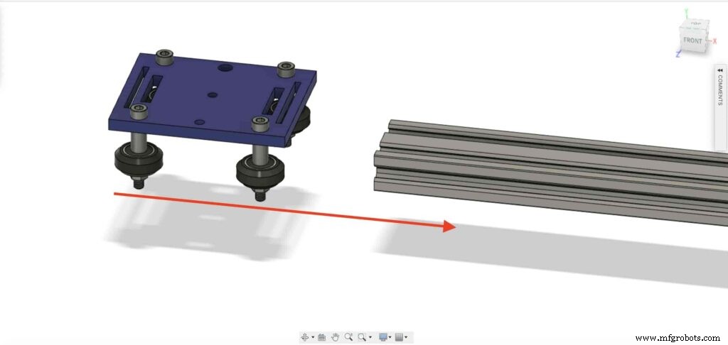
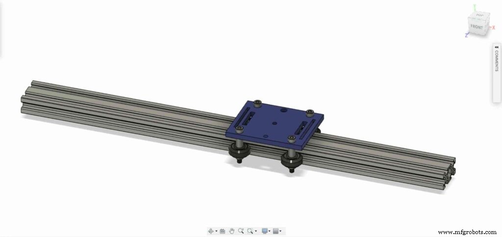
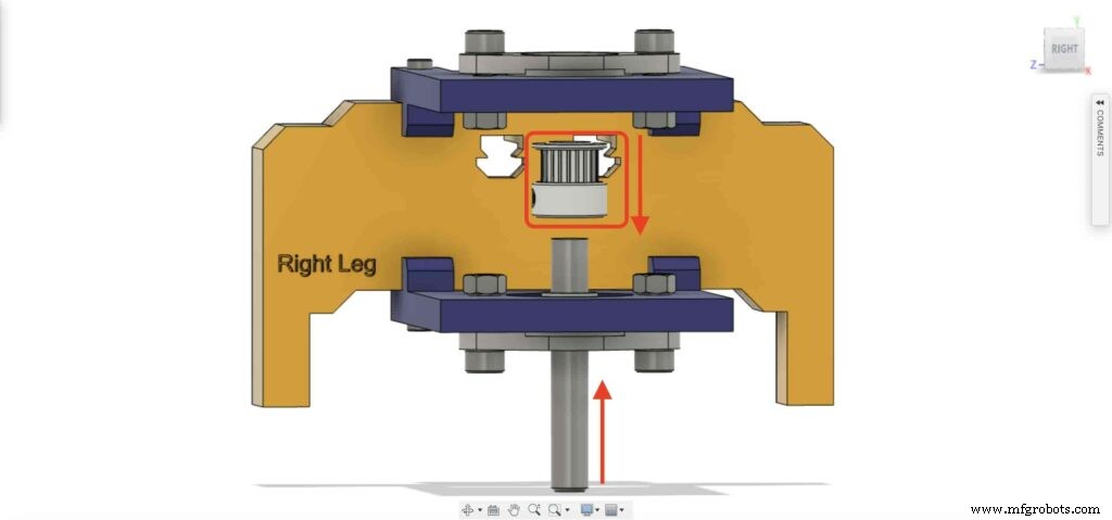
우리는 Openbuilds 하드웨어를 사용하여 카메라가 계속 이동할 수 있도록 가이드로 V-슬롯 2040 선형 레일인 기계적 구조를 구축하고 있습니다. 두 개의 풀리, 하나는 스테퍼 모터 샤프트에 있습니다. 그리고 다른 하나는 스테퍼 모터 회전 운동에서 선형 운동으로 변환하기 위해 그들 사이에 열린 타이밍 벨트가 있는 슬라이더 반대쪽의 8mm 선형 레일 샤프트에 있습니다.
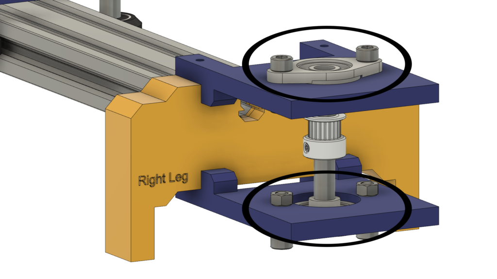
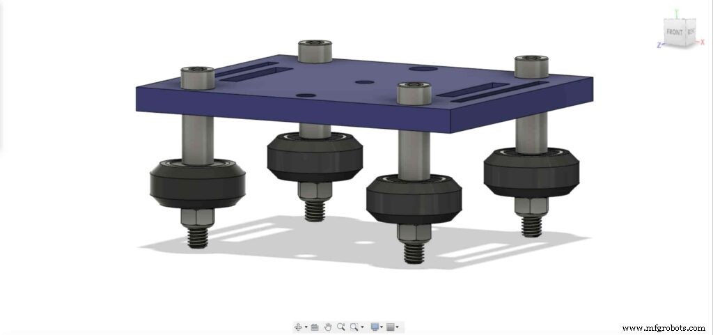
8mm 선형 레일 샤프트는 4개의 M5 나사로 상단 및 하단 플레이트에 설치된 2개의 자동 정렬 필로우 플랜지 블록 베어링 사이에 설치됩니다.
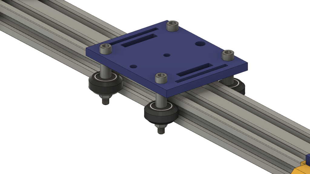
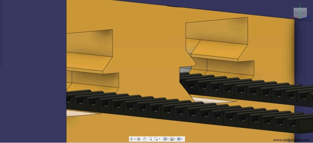
카메라 움직임을 극도로 부드럽게 만들기 위해 V-슬롯 레일의 V-홈에 있는 4개의 델린 V-슬롯 솔리드 휠을 사용하고 있습니다. 카메라 플레이트 중앙에는 표준 삼각대 나사용 1/4인치 직경 구멍이 있어 카메라를 쉽게 장착할 수 있습니다.
마지막으로 전자 제품용 인클로저, 모든 카메라 슬라이더 부품은 m3*16mm 나사와 너트로 함께 고정됩니다.
디지털 제작(3d 인쇄)
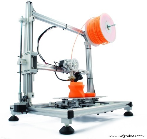
모든 카메라 슬라이더 본체는 0.2 레이어 높이, 20% 채우기로 3D 인쇄되며 카메라 슬라이더 왼쪽 및 오른쪽 다리를 제외하고 0.2 레이어 높이, 50% 채우기로 인쇄됩니다.
다음에서 STL 파일을 다운로드할 수 있습니다. 싱기버스.
V-휠 키트 어셈블리
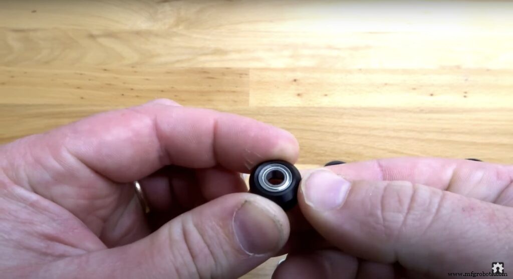
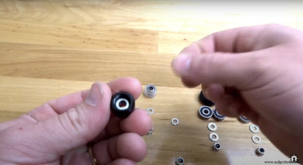
조립 과정은 매우 쉽습니다. 첫 번째 단계에서는 4개의 Solid V-Wheels를 조립해야 합니다. 견고한 V-휠 키트는 고무 휠, 2개의 베어링, 2개의 정밀 심 및 잠금 너트와 함께 제공됩니다.
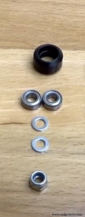
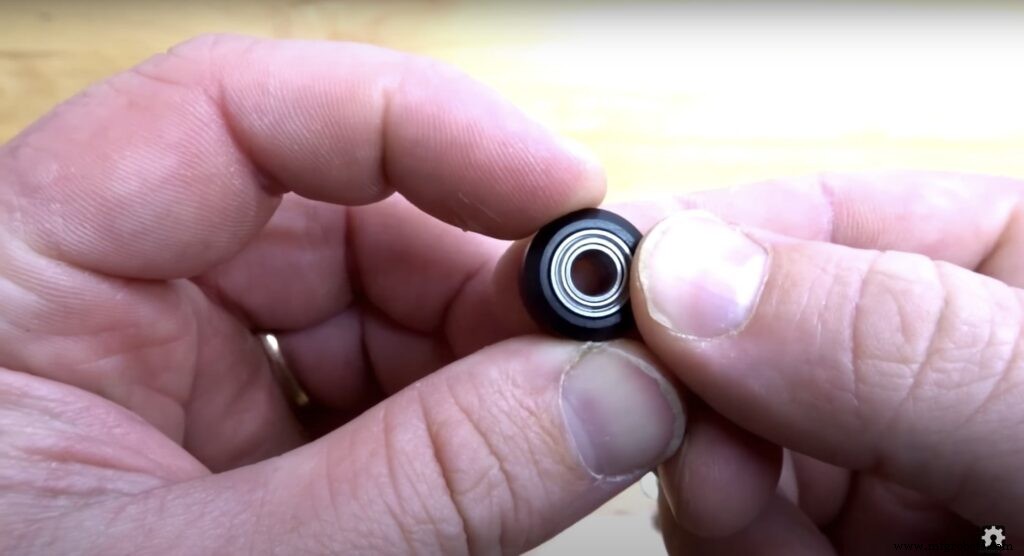
고무 바퀴의 한쪽에서 베어링을 삽입하고 바퀴를 뒤집은 다음 고무 바퀴 내부에 하나의 정밀 심을 삽입하고 마지막으로 두 번째 면에서 두 번째 베어링을 삽입합니다.
카메라 슬라이더 기계 조립
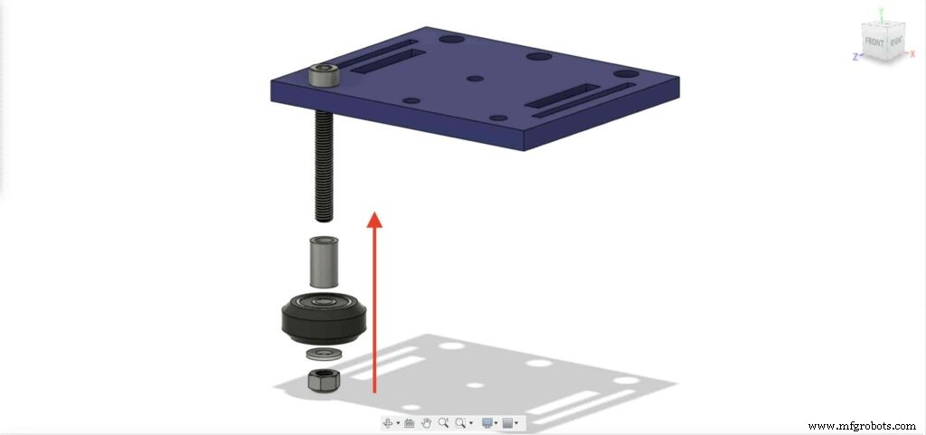
먼저 카메라 플레이트와 4개의 견고한 V-Wheels를 조립해야 합니다. 9mm 알루미늄 스페이서, 정밀 심, 잠금 너트를 사용합니다.

다른 세 바퀴로 이전 단계를 반복합니다. 두 개의 오른쪽 바퀴에서 9mm 스페이서를 사용할 것입니다. 그리고 나머지 두 개의 왼쪽 바퀴는 9mm 스페이서 대신 3mm 스페이서와 함께 편심 스페이서를 사용할 것입니다.
이제 V 슬롯 프로파일에 카메라 홀더 플레이트를 삽입합니다. 플레이트가 헐거워지고 흔들리는 경우 단단한 플레이트가 될 때까지 편심 너트를 조일 수 있습니다.
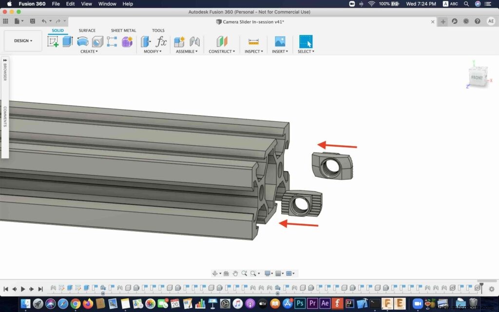
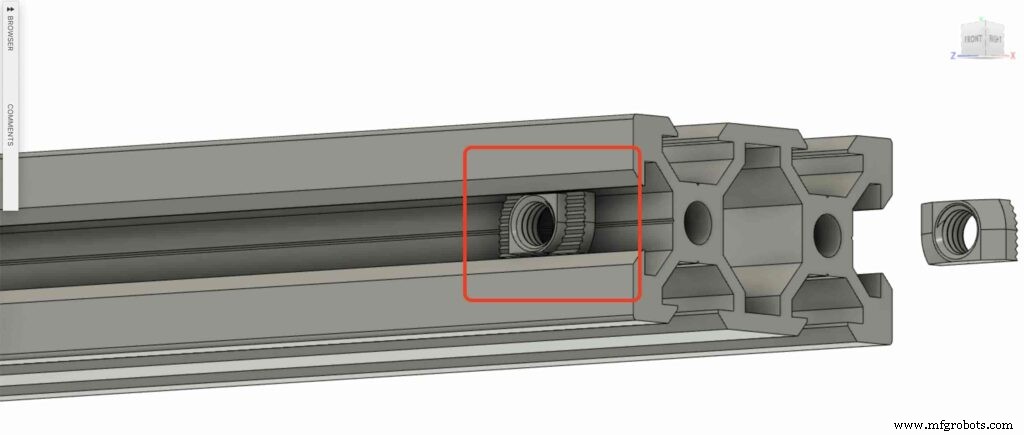
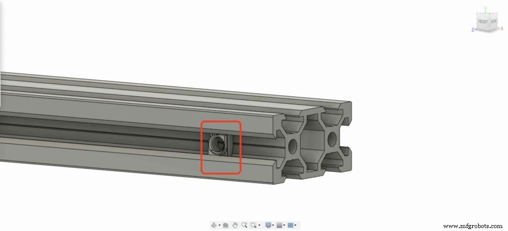
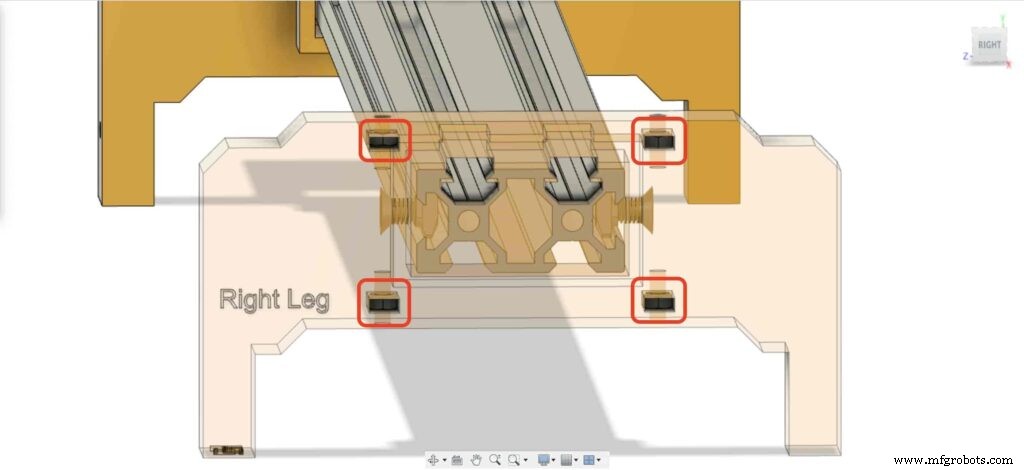
V 슬롯 프로파일의 각 끝에 2개의 드롭인 T형 너트를 삽입하겠습니다. 카메라 슬라이더의 오른쪽 및 왼쪽 다리에 V 슬롯 프로필을 연결해야 합니다.
2개의 카메라 슬라이더 다리를 가져와 V 슬롯 프로필에 밀어 넣습니다.
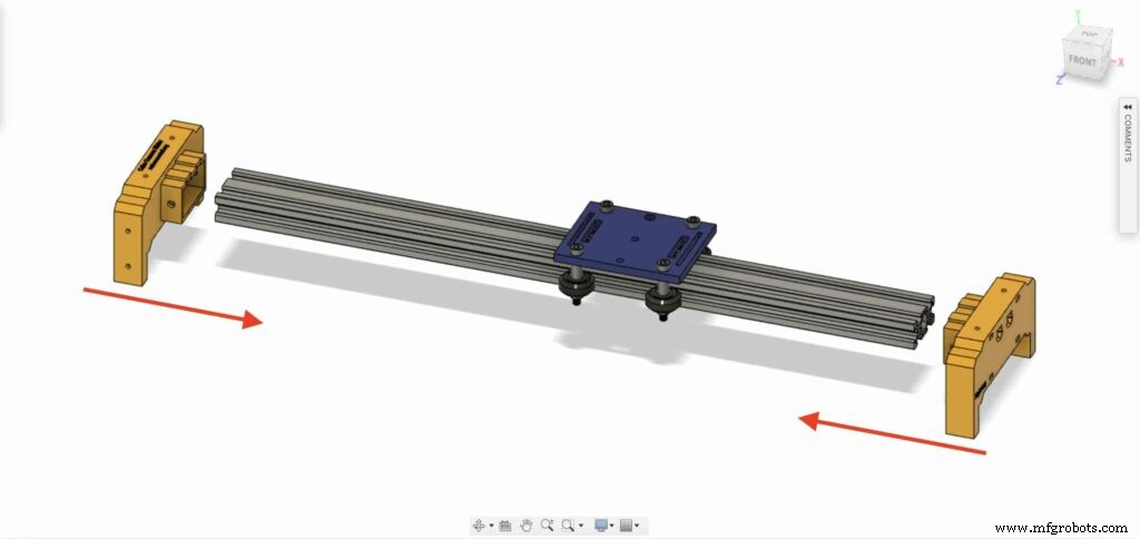

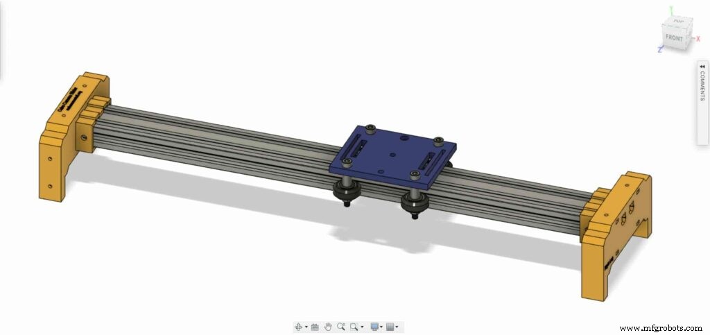
M5X10mm 나사 4개를 가져와 V 슬롯 프로파일로 다리 2개를 고정합니다.
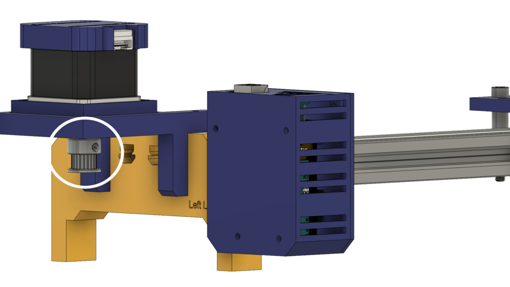
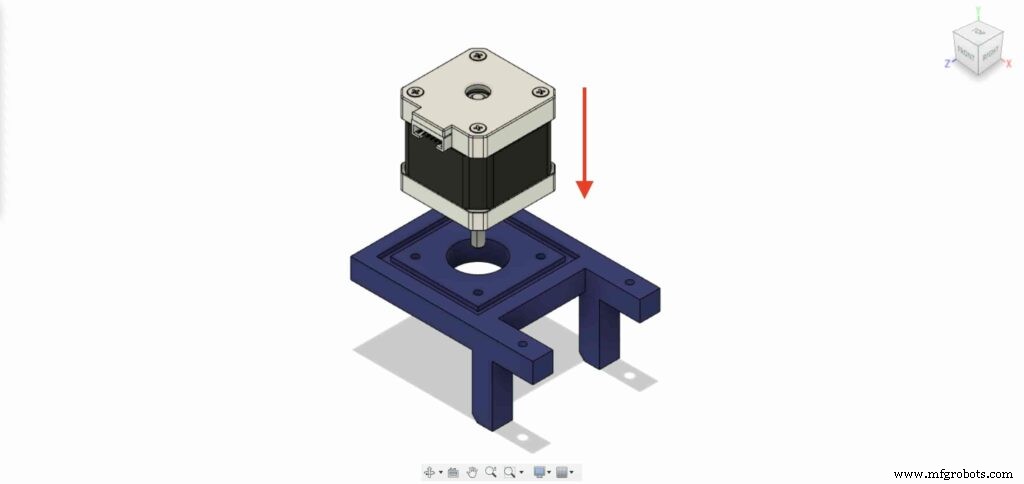
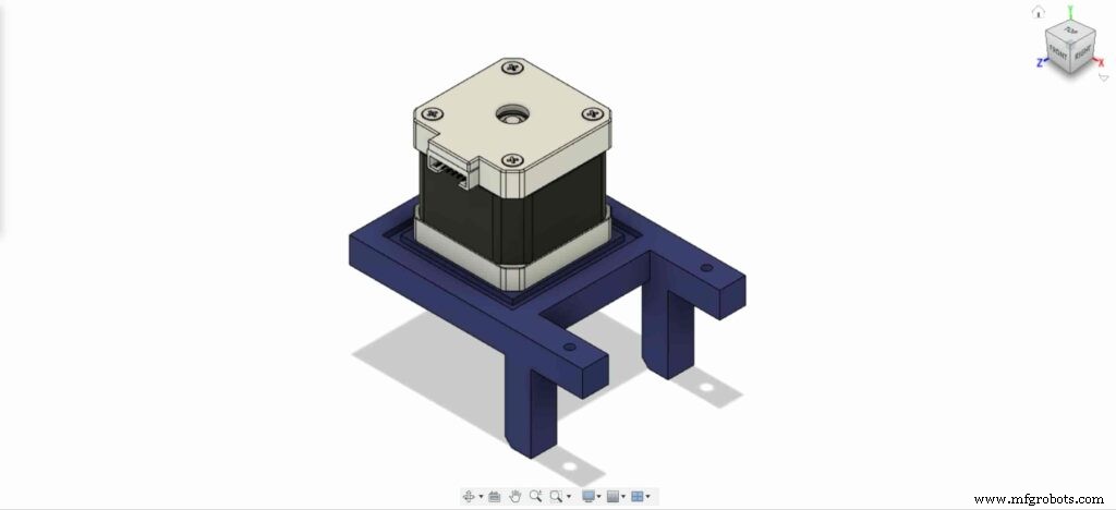
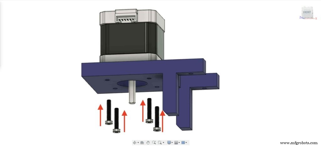
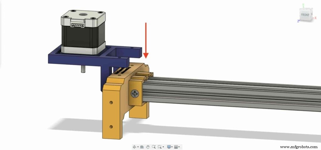
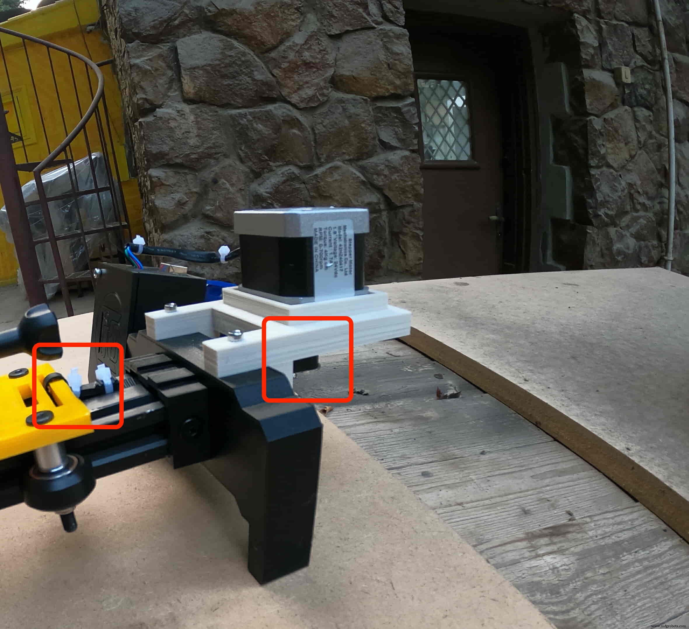
NEMA 17 스테퍼 모터를 플레이트에 설치해야 합니다. 그런 다음 4개의 M3X16mm 나사를 사용하여 모터를 제자리에 고정합니다.
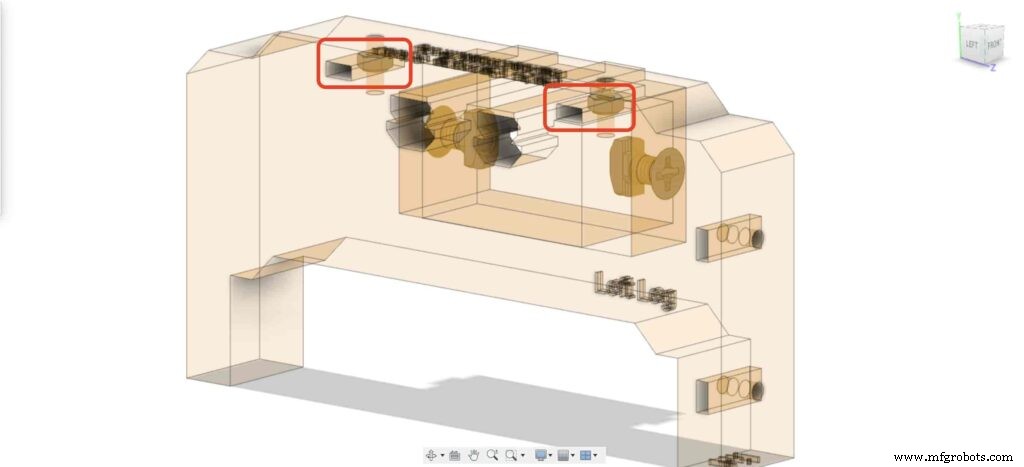
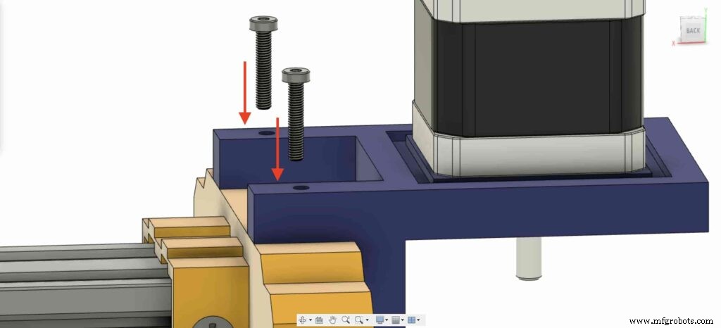
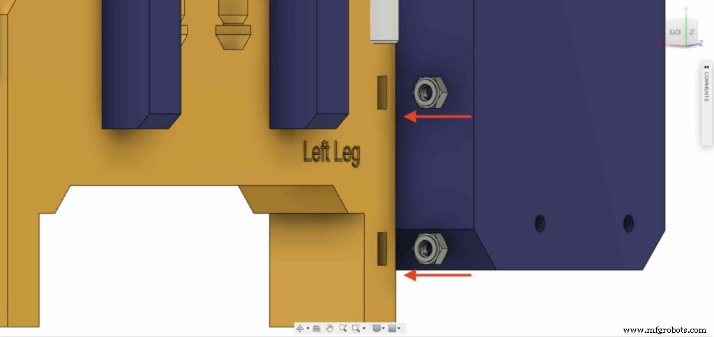
왼쪽 다리의 왼쪽 다리 상단 너트 위치에 두 개의 너트를 삽입하십시오.
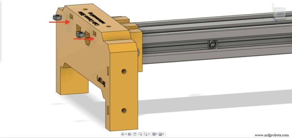
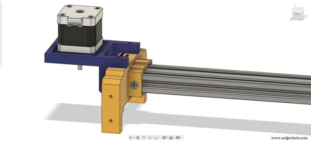
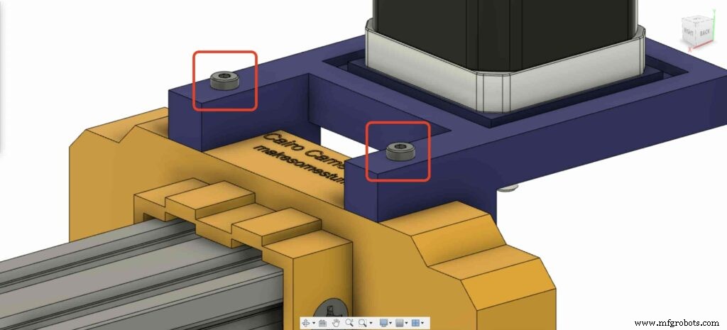
NEMA 17 모터 플레이트를 가져와 왼쪽 다리 상단에 고정합니다. 그리고 두 개의 M3X16mm 나사를 사용하여 왼쪽 다리의 플레이트를 고정합니다.
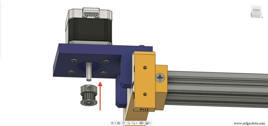
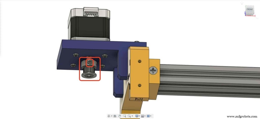
스테퍼 모터 회전 운동을 선형 운동으로 변환하려면 모터 샤프트에 GT2 보어 5mm 풀리를 설치해야 합니다. 그리고 육각 렌치를 사용하여 풀리 고정 나사를 조여 제자리에 고정합니다.
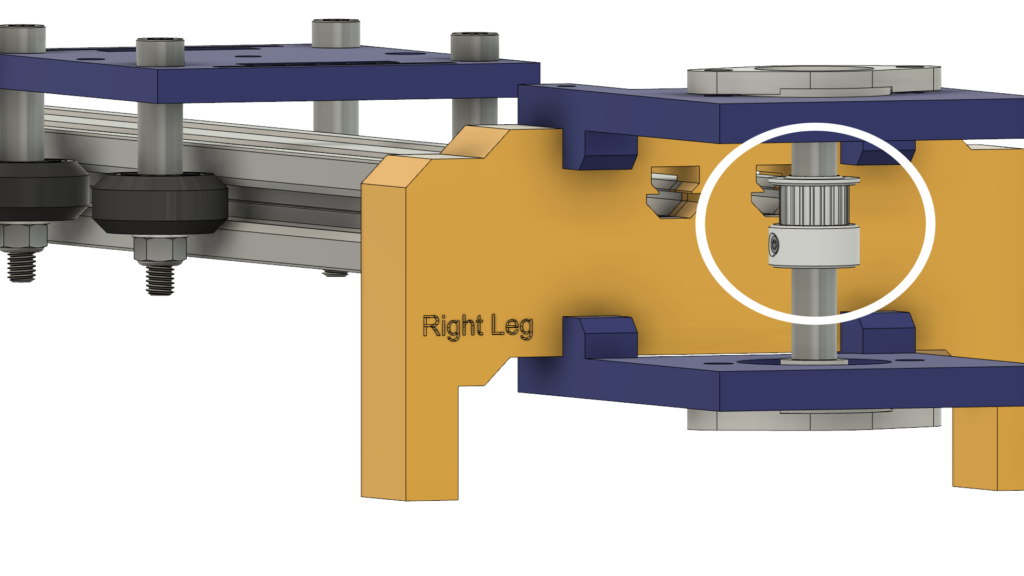
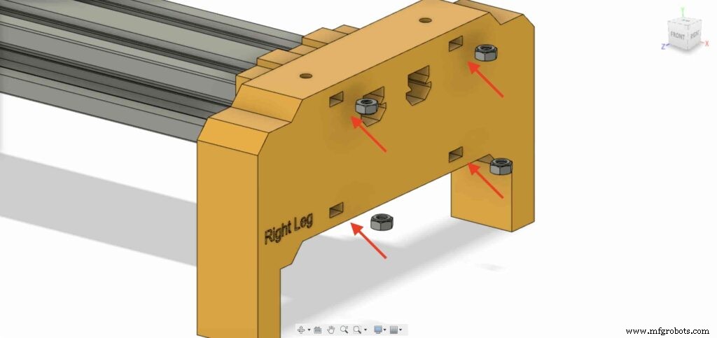
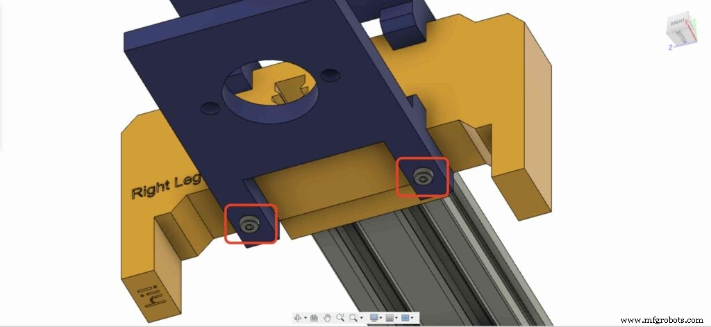
카메라 슬라이더 오른쪽 다리로 이동하여 다리 너트 위치에 4개의 M3 너트를 삽입합니다.
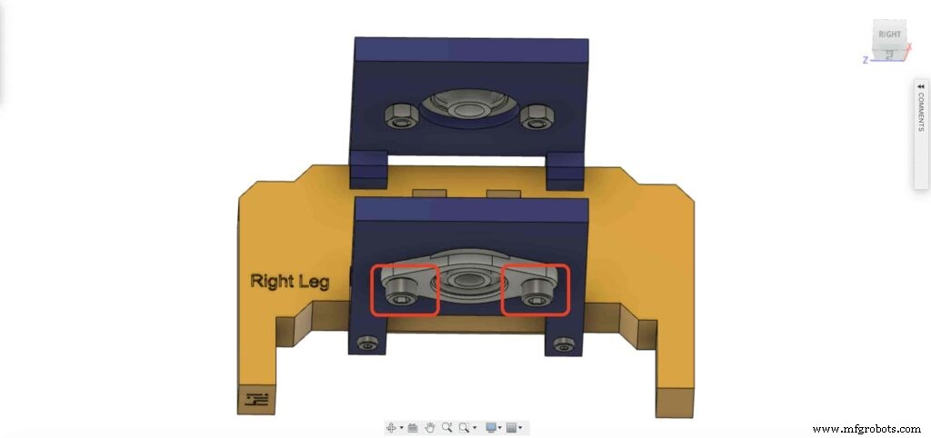
그런 다음 카메라 슬라이더 오른쪽 다리의 상단에 오른쪽 다리 베어링 두 개의 플레이트를 놓습니다.
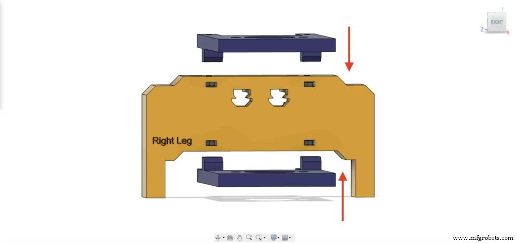
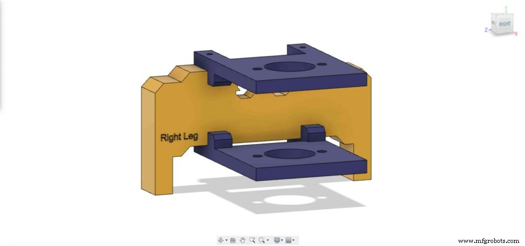
4개의 M3X16mm 나사를 사용하여 두 개의 플레이트를 카메라 슬라이더 오른쪽 다리에 고정하여 제자리에 고정합니다.
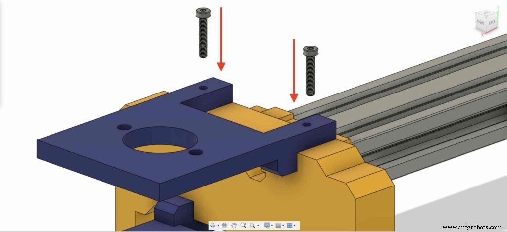
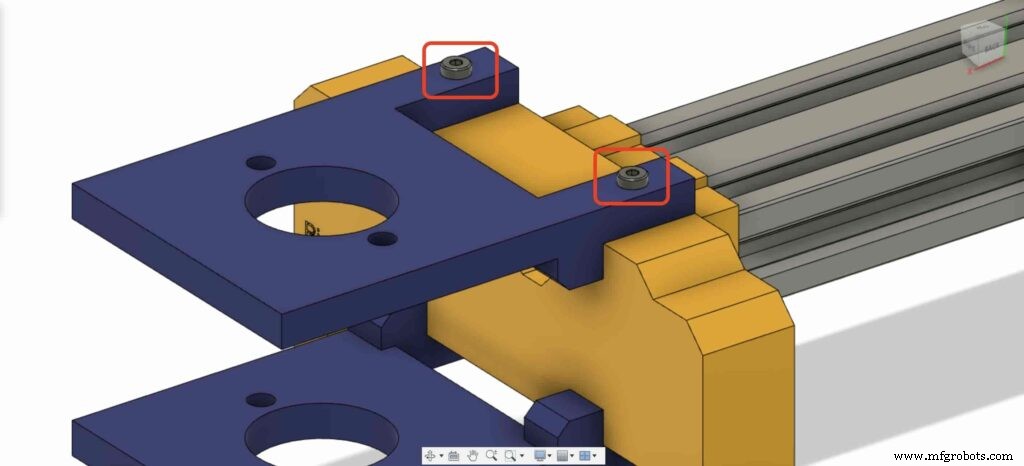
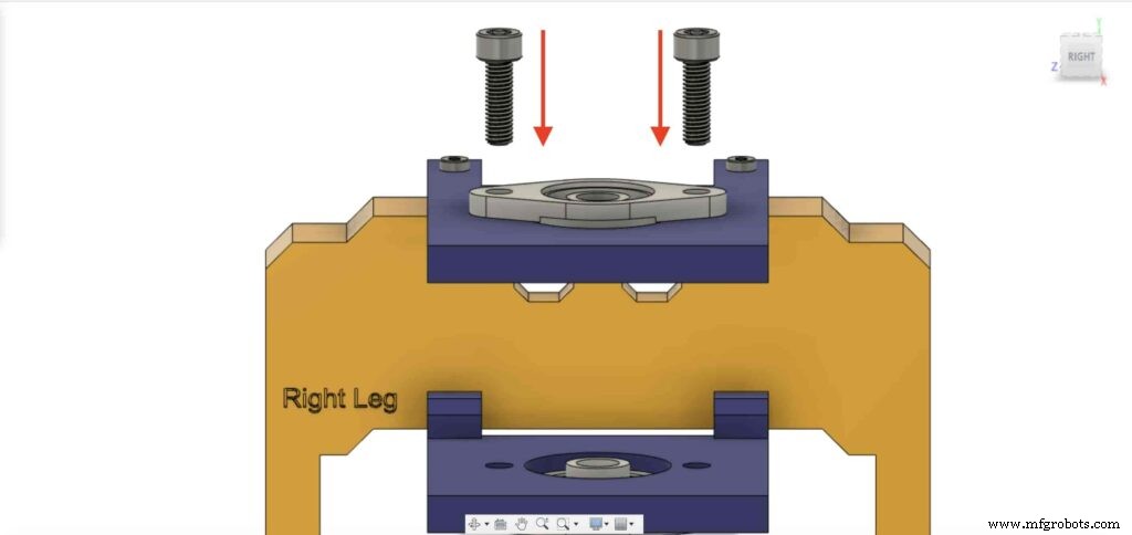
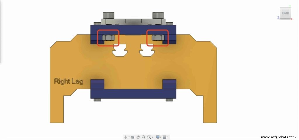
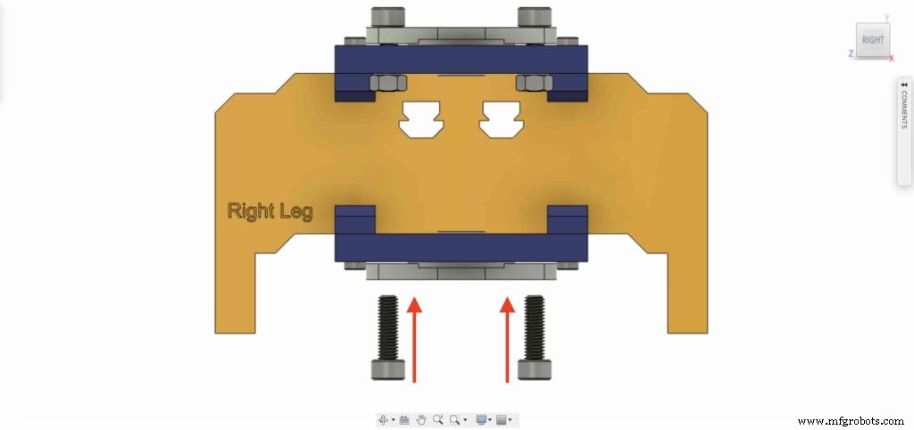
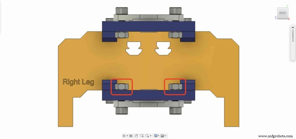
8mm 플랜지 블록 베어링 중 하나를 가져와 오른쪽 상단 다리 플레이트에 설치합니다. 2개의 M5X20mm 나사와 2개의 M5 너트를 사용합니다.
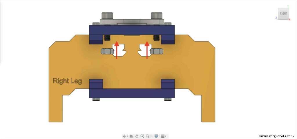
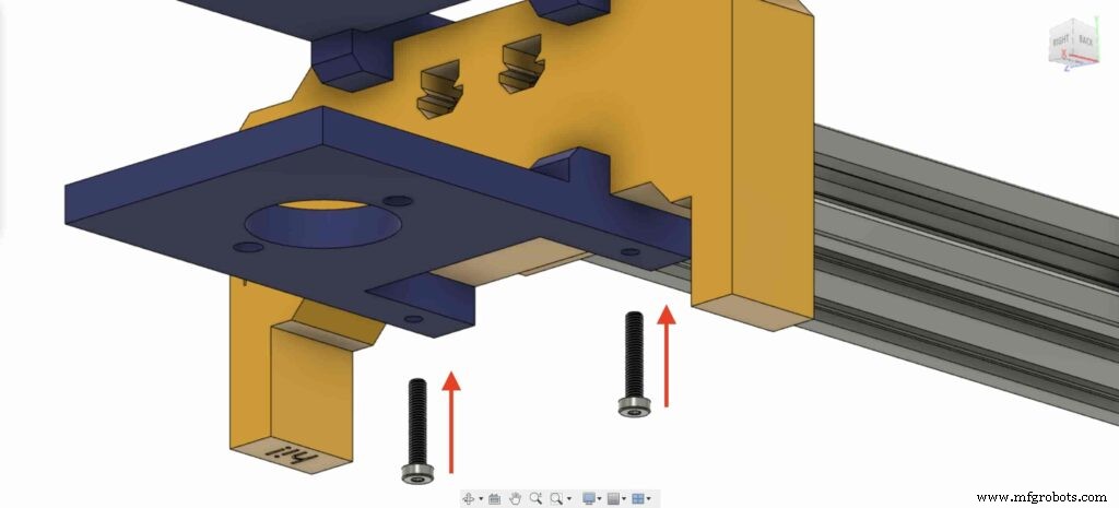
두 번째 8mm 플랜지 베어링 블록으로 이전 단계를 반복하여 카메라 슬라이더 오른쪽 다리 바닥 플레이트에 고정해야 합니다.
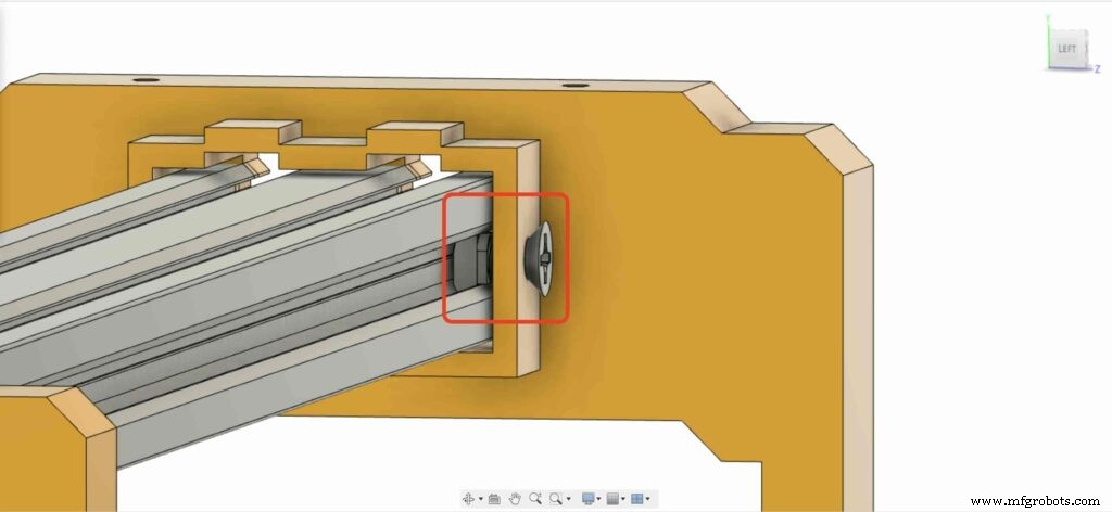
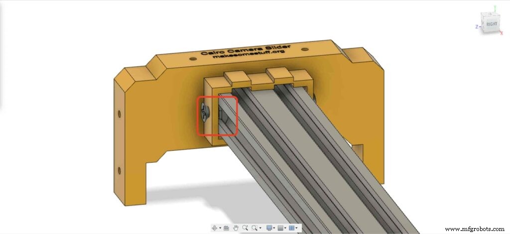
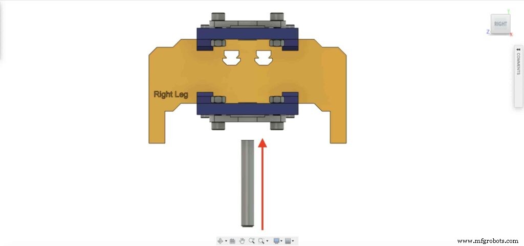
8mm 선형 레일 샤프트를 아래쪽에서 8mm 플랜지 베어링 블록에 삽입하고 위쪽으로 밀어 넣습니다. 그런 다음 8mm 보어 풀리를 리니어 레일 샤프트에 삽입하고 풀리의 고정 나사를 조여 고정합니다.
체크포인트, 이제 한 가지를 제외한 모든 카메라 슬라이더 메커니즘을 조립했습니다. 타이밍 벨트. 해보자.
NEMA17 모터 5mm 보어 풀리에서 6mm 타이밍 벨트를 돌립니다. 또한 오른쪽 다리에는 8mm 보어 풀리. 마지막으로 카메라 플레이트로 벨트를 조입니다.
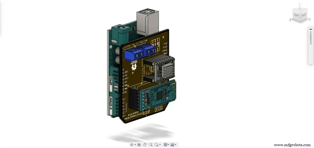
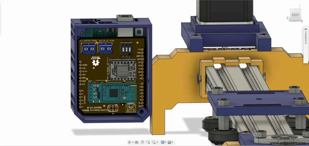
이제 컨트롤 보드를 조립할 차례입니다. Arduino 보드 상단에 Cairo Camera Slider Arduino 실드를 삽입합니다.
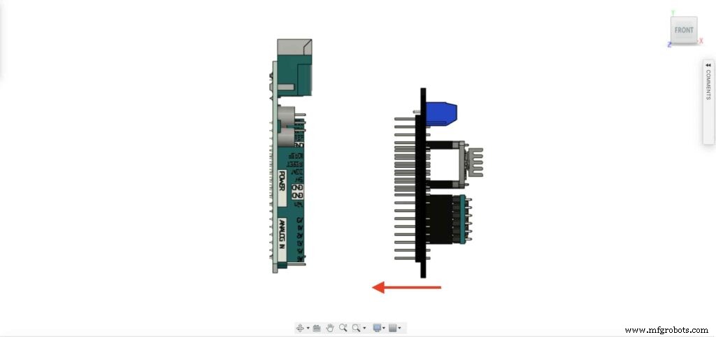
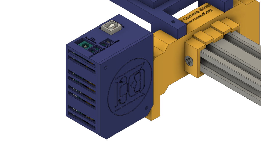
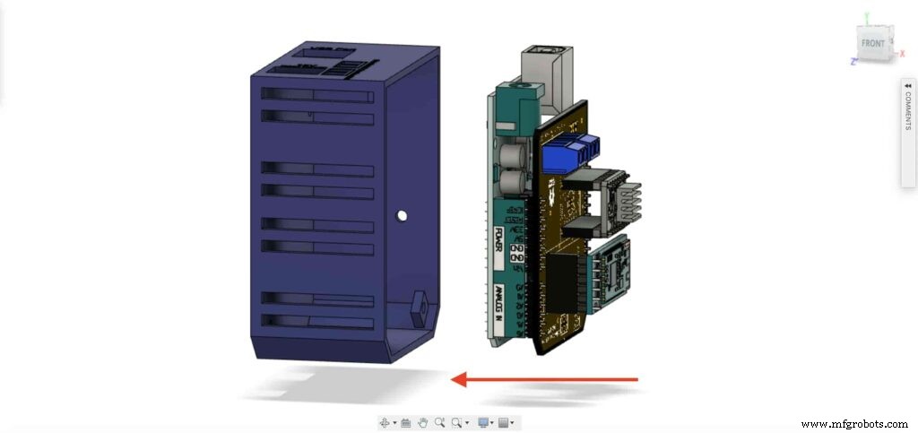
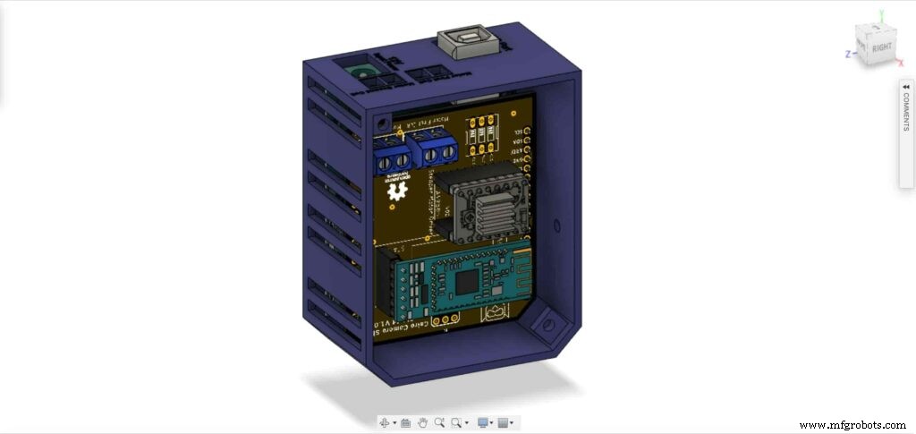
Arduino 보드와 Cairo 카메라 슬라이더 실드를 제어 보드 인클로저 내부에 삽입합니다.
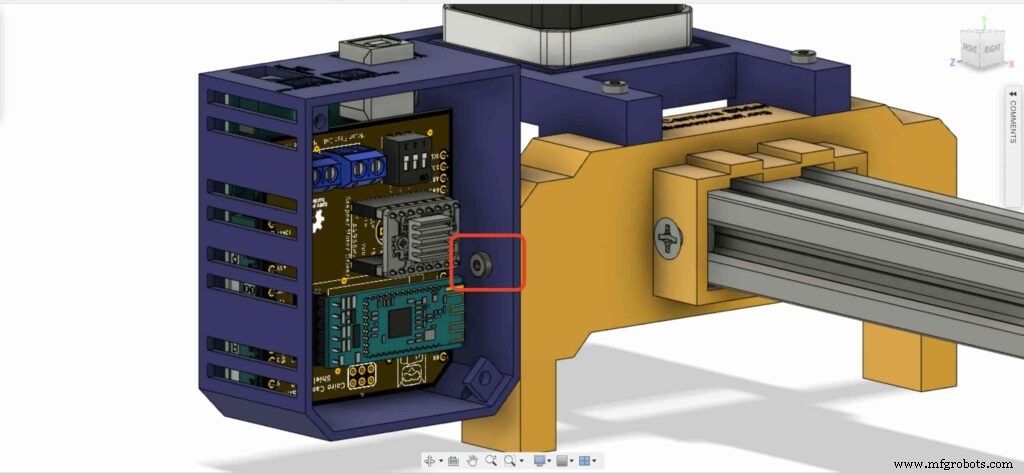
왼쪽 다리 너트 위치에 M3 너트 2개를 삽입합니다.
M3X16mm 나사를 사용하여 제어 보드 인클로저를 Cairo 카메라 슬라이더 왼쪽 다리에 설치합니다.

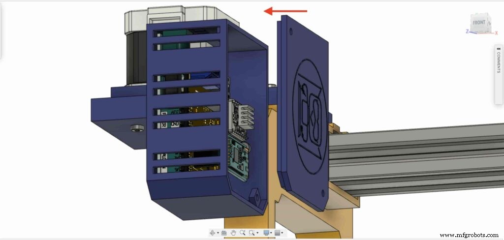
M3 나사 2개와 너트로 인클로저 상자 윗면을 닫으면 끝입니다!

Stepper Motor Test Control
After assembling all the parts together, We need to test it to make sure that everything is installed in its place correctly. Now, we need to connect the stepper motor with the Arduino board through the A4988 stepper motor driver and write some code to run that thing.
A4988 stepper motor driver
To control any stepper motor using the Arduino board or any microcontroller, you will need a stepper motor driver which works as a translator, takes commands from the Arduino board and translate it to the language that the motor understands.
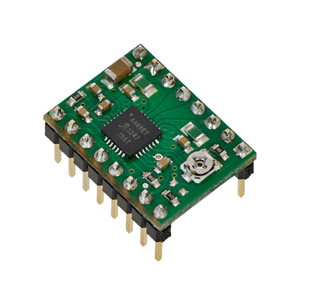
there are a lot of stepper motor drivers out there but we will use the A4988 driver . This driver allows us to control one bipolar motor at up to 2A output current per coil, it’s very simple to interface with the Arduino board you only need two digital pins to fully control your motor step and direction, allows you to control the maximum current output easily with an onboard potentiometer, and gives you a micro-step resolution down to 1/16 micro-step.
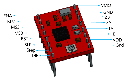
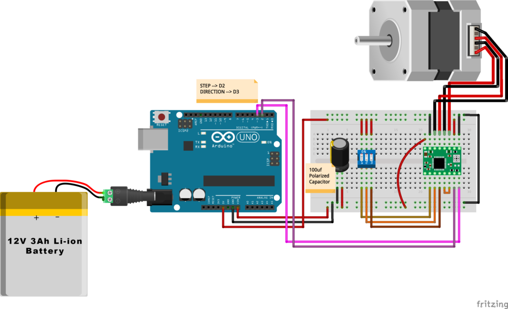
VMOT, GND: It’s the power connection pins for the stepper motor itself, it can be 8V-35V. In our case, we are connecting a 12V 3A power source on those pins with a 100uf decoupling capacitor to protect the A4998 board from any power spikes.
2B, 2A: the output pins for the stepper motor first coil which can deliver up to 2A.
1A, 1B: the output pins for the stepper motor second coil which can deliver up to 2A as well.
VDD, GND: Used for driving the internal logic circuitry, it can be 3V to 5.5V. It’s totally isolated from the VMOT pin.
EN: Stands for “Enable” it’s an active LOW(0V) input pin, which means when this pin pulled LOW(0V) the A4988 chip is enabled. And when pulled HIGH(5V) the A4988 chip is disabled. By default, this pin is pulled LOW(0V). So, the chip is always enabled unless you pull it HIGH(5V).
MS1, MS2, MS3: Through these pins, you can select your motor microstepping resolution(step size). The A4988 gives you five different microstep resolutions (full step, half step, quarter step, Eighth step, Sixteenth step) . By applying appropriate logic levels to these three pins we can set the motors to one of the five step resolutions.
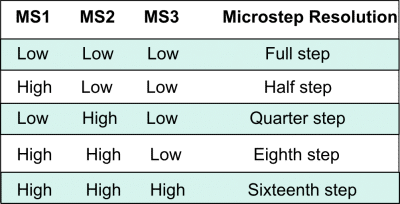
By default, the MS1, MS2, MS3 pins have internal pull-down resistors. So leaving these three microstep selection pins disconnected results in full-step mode.
RST, SLP: The “Reset” pin is an active LOW(0V) input pin, which means when it pulled LOW(0V), all the step inputs are ignored it also resets the translator itself until you pull it HIGH(5V). The “Sleep” pin also an active LOW pin, pulling it LOW, puts the driver in the sleep mode minimizing the power consumption. By default, the “Sleep” pin is pulled HIGH(5V).
STP, DIR: The “Step” pin is responsible for controlling the number of steps that the motor is rotating, each pulse to the “Step” pin corresponds for one microstep in the direction selected by the “Direction” pin, the faster the pulses, the faster the motor will rotate. By applying logic value HIGH(5V) on the “Direction” pin it makes the motor rotate clockwise, by applying LOW(0V) it makes the motor rotate counterclockwise(it may differs from one to another according to your motor wiring with the driver).
NEMA17 Stepper Motor
Stepper motors are DC motors that can rotate in precise increments, they are used in many applications like 3D printers to align the printhead and CNC machines to control the movement of the cutting tool and this is because they are very accurate and precise.
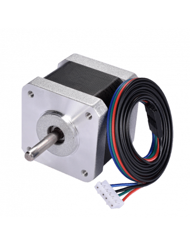
Unlike DC motors, stepper motors are controlled by applying DC electrical pulses to their internal coils. Each pulse makes the shaft advance by one step or a fraction of step which is called “Microstepping”. So, you can control precisely how many steps or even fraction steps you want the motor shaft to move. Another great advantage of using stepper motors is that it can move very precisely and accurately at very slow speeds without even stalling.
The type of motor we are using in this project is the NEMA 17 Bipolar stepper motor . The bipolar stepper motor has two internal coils and it usually has four wires, two wires per coil. unlike the Bipolar stepper motor which has five wires. The “Step Angle” of the motor is 1.8° which indicates how much the shaft advances in each full step, the motor works on 9V but if you want to get the maximum power of it use a 12V power source.
So, by connecting the stepper motor with the A4988 stepper motor driver, we can control how many steps we need the motor to move and in what direction. Also, we can set the “microstep” mode is it full step, half step, quarter step, ….. Let’s take a look at the wiring diagram.
Wiring Diagram
As we stated before, we need to make a small check to make sure that everything we assembled before is right in its place and moving properly. Now, we will wire all the hardware together, the NEMA 17 stepper motor with the A4988 stepper motor driver to the brain, the Arduino board. And using a 12V 3A Lithium-Ion battery to feed the motors with the power it needs.
Arduino Code
AccelStepper Library Installation
The Installation is pretty simple, we need to open Arduino IDE. From the “Sketch” menu. Select Include Library –> Manage Libraries…
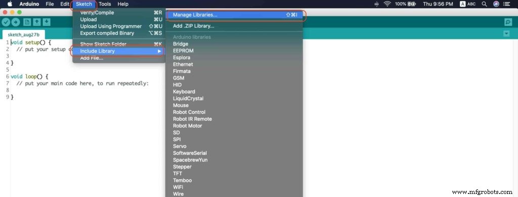
A new window should appear, search for “AccelStepper” and install the library made by “Mike McCauley”. Easy right!
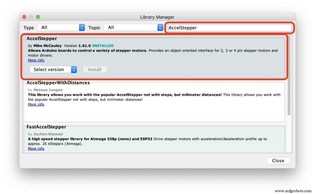
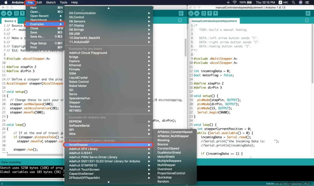
After installing the AccelStepper library, you should see it in the examples menu.
I wanna make sure that the AccelStepper library is installed correctly and my stepper motor connection with the A4988 motor driver is right and my power management is fine. So, let’s write some lines of code to run our stepper motor forward and backward.
// Bounce stepper test program
// Make a single stepper bounce from one limit to another
// Copyright (C) 2020 makesomestuff.org

#include
#define stepPin 2
#define dirPin 3 // Define a stepper and the pins it will use

AccelStepper stepper(AccelStepper::DRIVER, stepPin, dirPin); //create an object. the pin "2" is the step pin, "3" is the direction pin.

void setup()
{
 // Change these to suit your stepper if you want
 stepper.setMaxSpeed(100);
 stepper.setAcceleration(20);
 stepper.moveTo(500);
}

void loop()
{
 // If at the end of travel go to the other end
 if (stepper.distanceToGo() ==0)
 stepper.moveTo(-stepper.currentPosition());
 stepper.run();
}
The code logic is pretty straightforward, we initialized an object from the AccelStepper library, we defined two constants (stepPin, dirPin) that two digital pins is used by the A4988 stepper motor driver to control the movement of the motor itself.
#include

#define stepPin 2
#define dirPin 3 // Define a stepper and the pins it will use

AccelStepper stepper(AccelStepper::DRIVER, stepPin, dirPin); //create an object. the pin "2" is the step pin, "3" is the direction pin.
Inside the void setup function, we set the Max. speed of the stepper motor to 100 steps/sec. Also, we set the acceleration/deceleration rate to 20 steps/sec. lastly, we used the moveTo() function to tell the motor to move 500 steps.
void setup()
{
 // Change these to suit your stepper if you want
 stepper.setMaxSpeed(100);
 stepper.setAcceleration(20);
 stepper.moveTo(500);
}
Inside the void loop function, we are checking if the motor reached it’s position or not. If it reached the position, it will bounce back. and if it didn’t reach it’s position yet, it will keep running.
void loop()
{
 // If at the end of travel go to the other end
 if (stepper.distanceToGo() ==0)
 stepper.moveTo(-stepper.currentPosition());
 stepper.run();
}
Camera Slider Full Wireless Control
We have done great things so far. Let’s continue! The next step after testing everything, is to work on the mobile app that we will use to control the camera slider movement and send the orders to it. Also, we need to work on the Arduino code that will receive the data from the mobile app and according to these data it will take some actions like moving the motor, changing speed, acceleration, and so on…
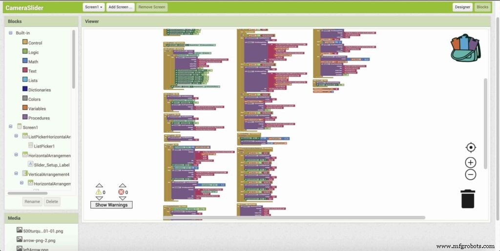
Building The Mobile App
To build the mobile app, I used the MIT App inventor tool that allows you to create mobile apps that run on any Android smartphone. The tool is pretty simple since you only drag and drop some pre-made code blocks to build the logic of your program, also you use some premade blocks to build the app user interface. You can access the source of the mobile app from the link down below. Feel free to edit and share, it’s open-source. Mobile App Source
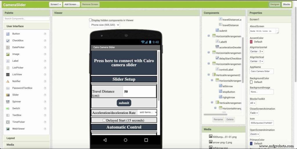
The image down below, a brief explanation for each button function and how it works.
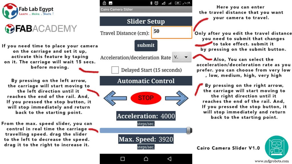
That mobile app will communicate with the Cairo camera slider wirelessly over the Bluetooth communication. So, the next step is to connect a Bluetooth module to the last circuit we built before and upload some lines of code to the Arduino board to be able to establish the communication between the mobile app and the Cairo camera slider.
Wiring Diagram
It’s the time to connect all things together, previously we connected the stepper motor, stepper motor driver, Arduino UNO, and the battery together and tested the circuit and it worked fine. Now, and after building the mobile app, we need to connect the HC-05 Bluetooth module to our circuit.
To make it wireless we will use the HC-05 Bluetooth module which has wide use, it can set as slave or master as well (unlike the HC-06 module which can work only as a slave) which means that you can make a Bluetooth connection between two different Arduino boards. the HC-05 Bluetooth module is an SPP (Serial Port Protocol) module, which means that it communicates with the Arduino board via the Serial communication. You only need to connect the Tx and the Rx pins between the HC-05 module and the Arduino UNO board.
<울>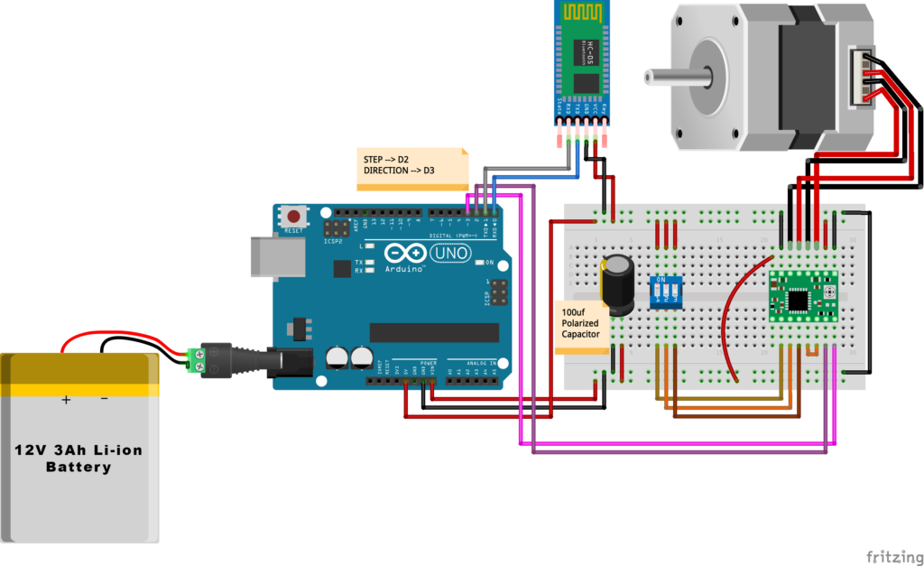
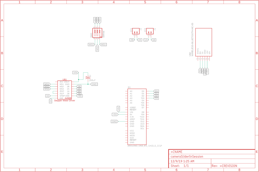
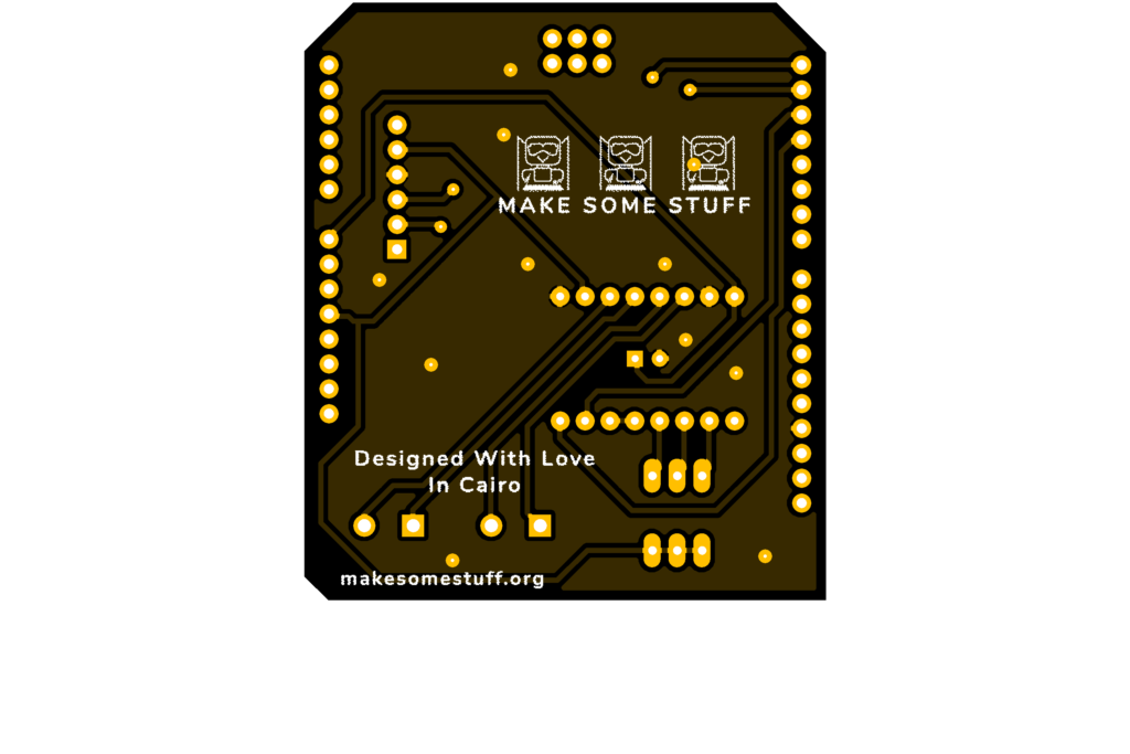
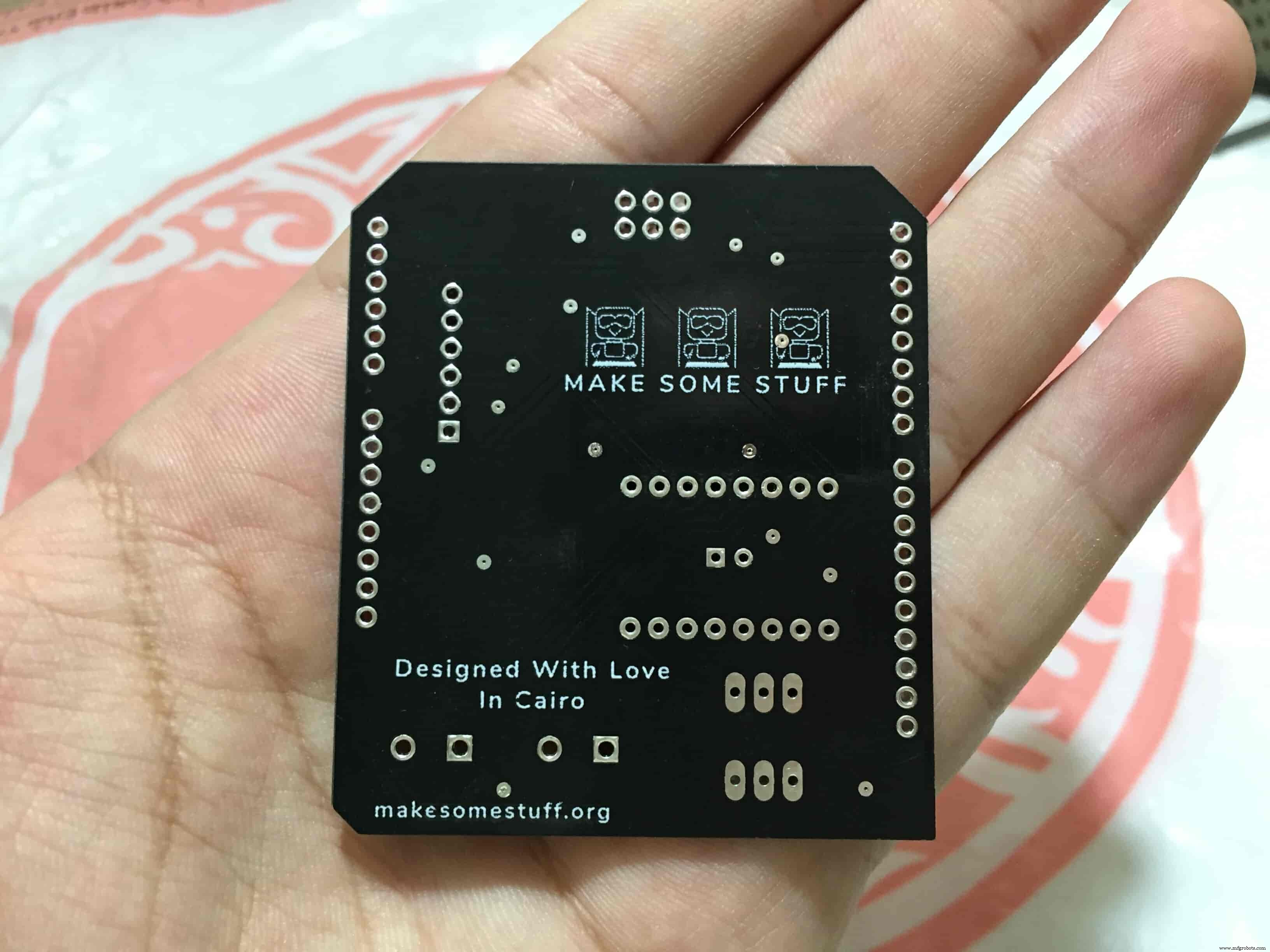
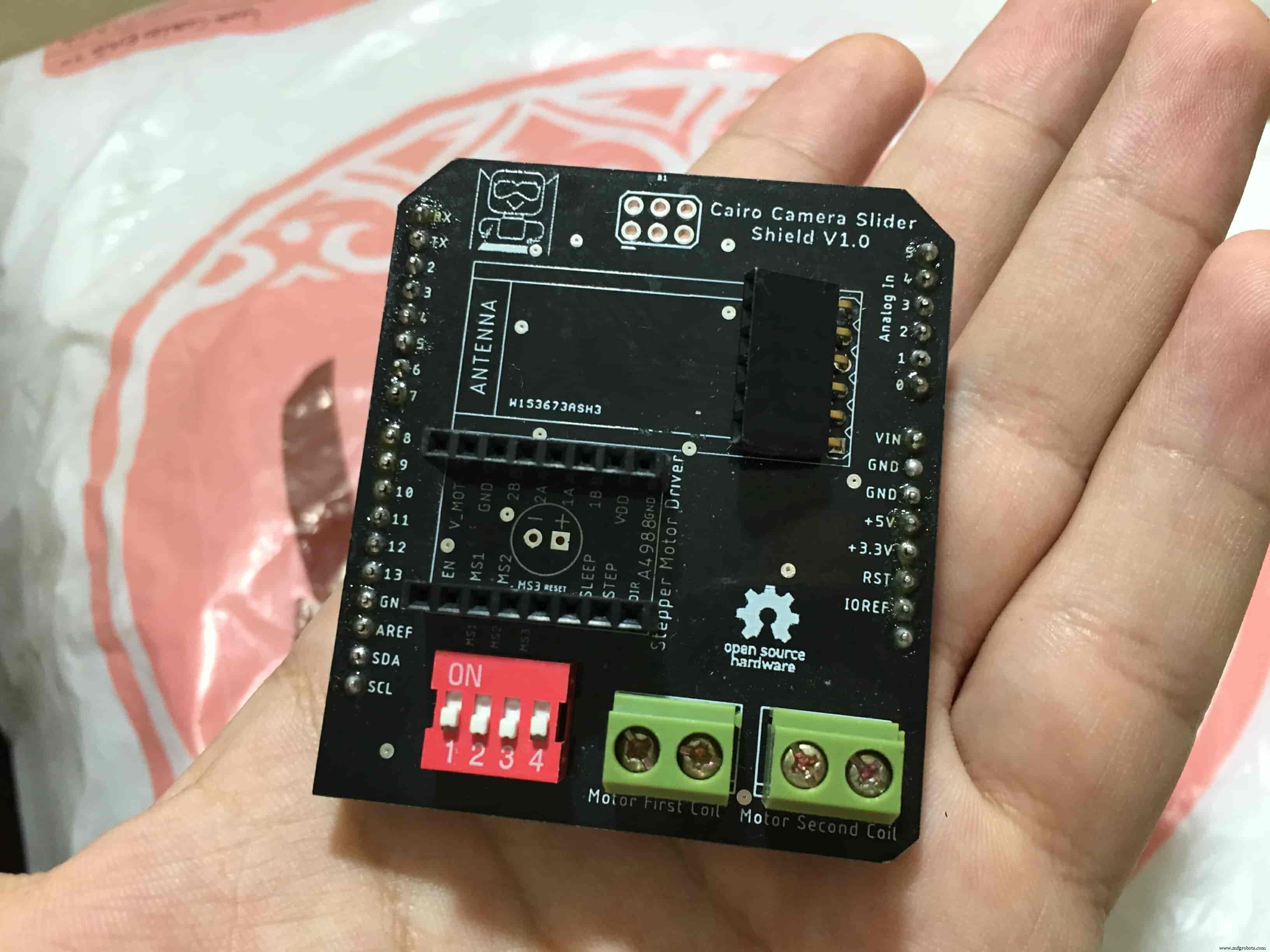
Schematic and PCB Fabrication
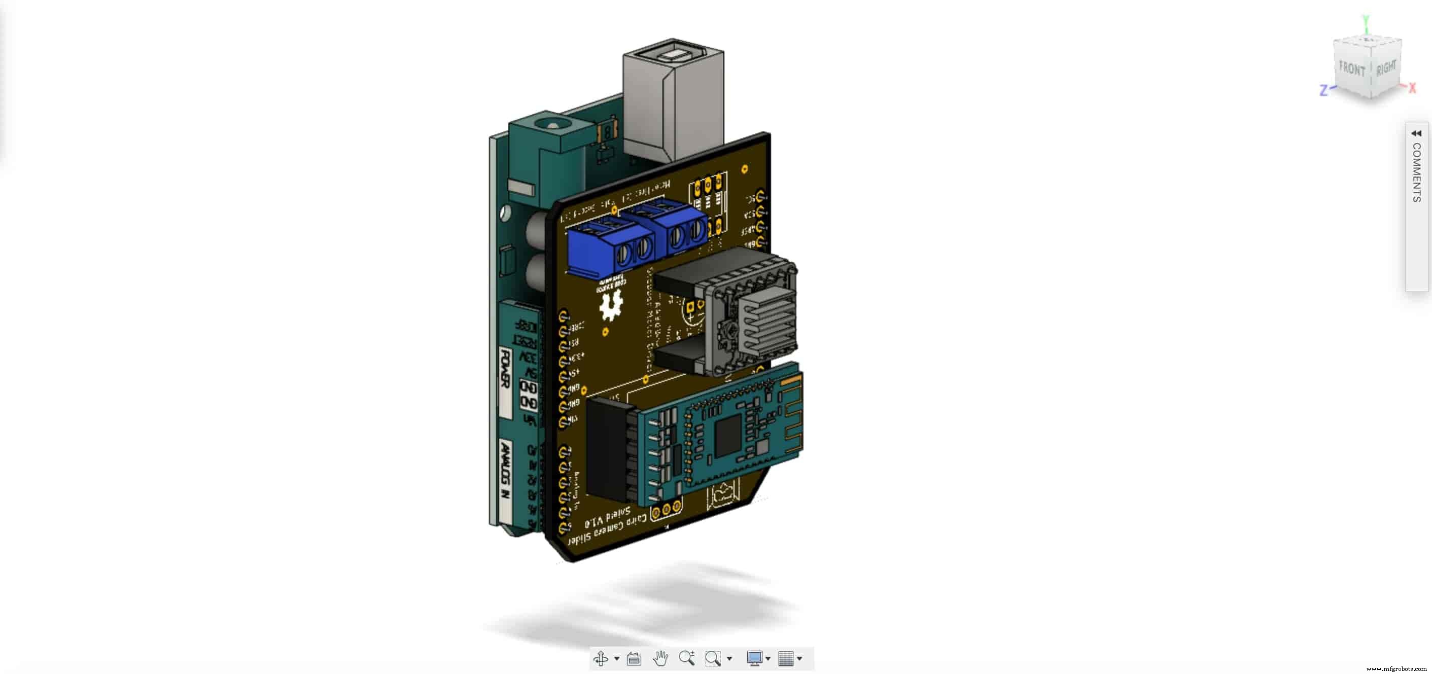
Man! I don’t like breadboarding a big circuit like this. So, I designed a super pretty Arduino UNO shield PCB board that keeps all my components in place without worrying about the jumper wires or even the connections. All you need to do is to place your component on the Arduino shield PCB, insert the HC-05 Bluetooth module, A4988 stepper motor driver, and the battery in their places. and install the shield on top of the Arduino board. that’s it!
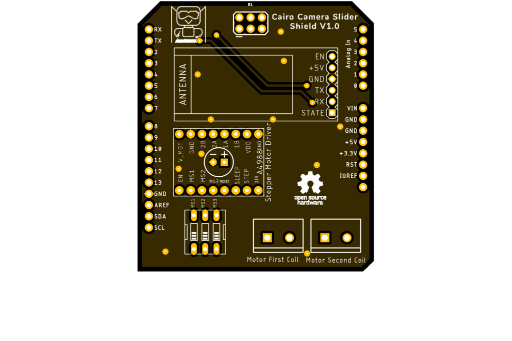
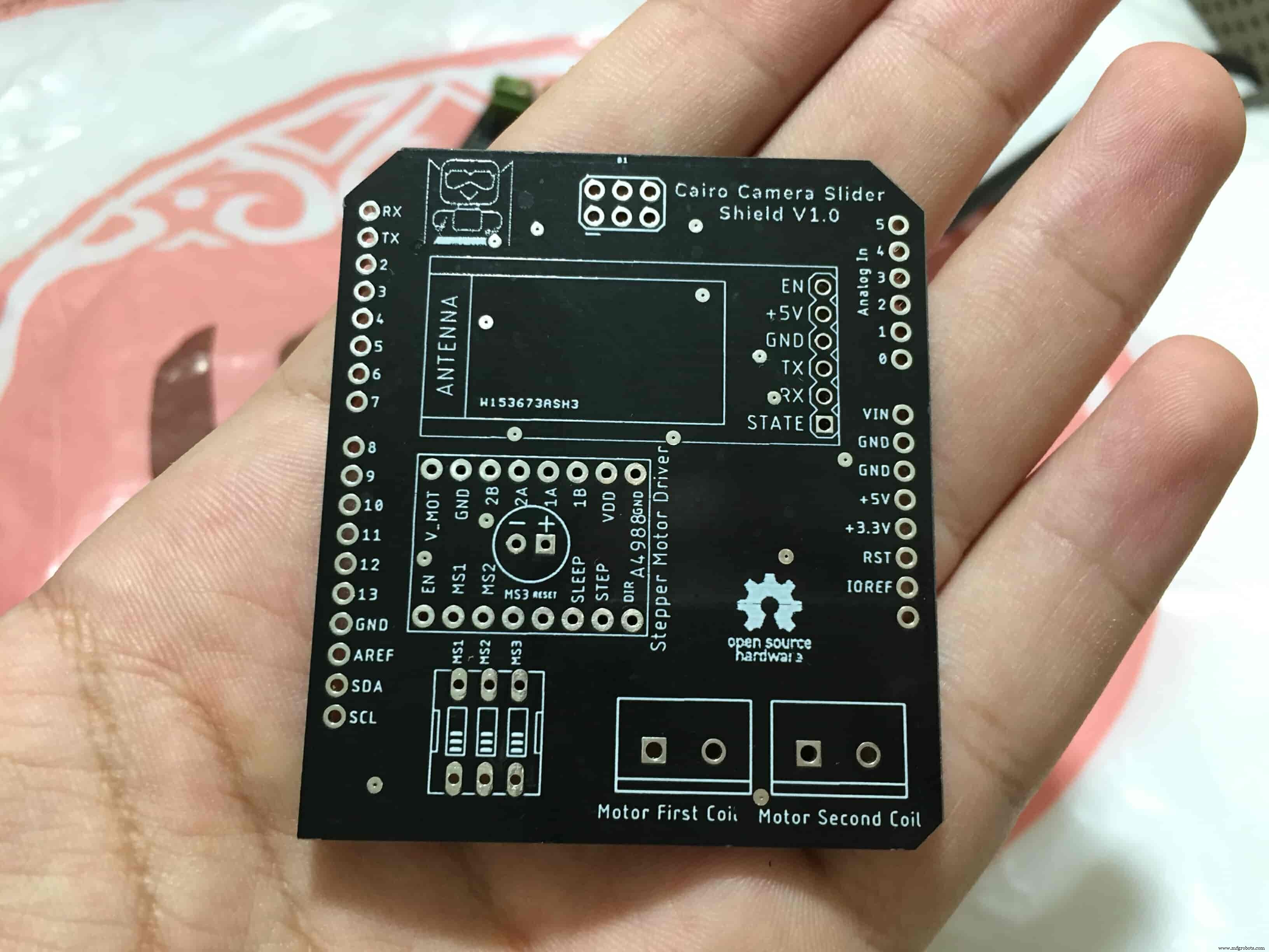
I fabricated my PCB at PCBWay the quality was very good, in a few days the package arrived in Egypt safely. and I paid just 5$ for the fabrication which is amazing. The coolest thing that I was able to check the order fabrication and processing status online on my account panel and track everything happening to my baby board like I was there inside the factory.
you can download the PCB design source files or even ordering the Cairo Camera Slider Arduino Shield PCB from the PCBWay website. PCB Source Files &Ordering

Arduino Code And Bluetooth Communication
/*
 TODO::Update the arduino program to Make the user able to choose the motor driver micro stepping mode. find and equation that helps to automatically adjust the the "steps" variable value.
 TODO::update the mobile app to ask the user on the beginning only about the [homing position(done), microstepping mode].
 TODO::Update the arduino program to make the code only iterates around the "homing position" &"microstepping mode" only once on the void setup() function.

 DATA::left arrow button sends --> 1.
 DATA::right arrow button sends --> 2.
 DATA::stop button sends --> 3.

 DATA::rail length (1cm - 1000cm) --> (201 - 1200).

 DATA::motor acceleration spinner Very High --> 14.
 DATA::motor acceleration spinner High --> 11
 DATA::motor acceleration spinner Medium --> 12
 DATA::motor acceleration spinner Low --> 13
 DATA::motor acceleration spinner Very Low --> 15

 DATA::motor speed slider (1 step/sec. - 4000 step/sec.) --> (5001 - 9000).

 DATA::delay start checkbox is true --> 7.
 DATA::delay start checkbox is false --> 8.

 DATA::left end homing --> 16.
 DATA::right end homing --> 17.

 DATA::Smooth movement Type --> 18.
 DATA::Very Smooth movement Type --> 19.

 1301 --> 2300
*/

#include
#include

#define stepPin 2
#define dirPin 3

bool homingPositionFlag =false;
int startupSetupFlag =0;
bool delayedStart =false;

int incomingData =0;
int movementDistance =50;
long steps =0; //50cm rail by default @1/8 microstepping.
int microStepResolution =0; //4 or 16
long railLength =0;
int sliderSpeed =10;

AccelStepper stepper(AccelStepper::DRIVER, stepPin, dirPin); //create an object. the pin "2" is the step pin, "3" is the direction pin.

void setup() {
 pinMode(stepPin, OUTPUT);
 pinMode(dirPin, OUTPUT);
 Serial.begin(9600);

 stepper.setMaxSpeed(10.00); //The fastest motor speed that can be reliably supported is about 4000 steps per second at a clock frequency of 16 MHz on Arduino such as Uno
 stepper.setAcceleration(500.00); //1600 (40%) (Medium Acceleration rate)

 while (startupSetupFlag <3) {
 if (Serial.available()> 1) {
 unsigned int dataOne =Serial.read();
 unsigned int dataOne1 =Serial.read();
 unsigned int incomingData =(dataOne1 * 256) + dataOne;

 //**************************************************************Motor Homing Part**************************************************
 if (incomingData ==16) { //left end homing position.
 stepper.setCurrentPosition(steps);
 homingPositionFlag =false;
 startupSetupFlag++;
 } else if (incomingData ==17) { //right end homing position.
 stepper.setCurrentPosition(-(steps));
 homingPositionFlag =true;
 startupSetupFlag++;
 }
 //**************************************************************microstep resolution Part**************************************************
 if (incomingData ==18) {
 microStepResolution =4; //50cm rail length @1/4 microstep resolution.
 startupSetupFlag++;
 } else if (incomingData ==19) {
 microStepResolution =16; //50cm rail length @1/16 microstep resolution.
 startupSetupFlag++;
 }

 if (incomingData>=1301 &&incomingData <=2300) {
 railLength =incomingData - 1300; //from raw data to cm.
 if (microStepResolution ==4) {
 steps =((6100L * railLength) / 50L);
 startupSetupFlag++;
 }
 else if (microStepResolution ==16) {
 steps =((25000L * railLength) / 50L);
 startupSetupFlag++;
 }
 }
 }
 //Serial.println(startupSetupFlag);
 }
 /*
 * *********** *********** **********For Debugging Purposes* *********** *********** **********
 Serial.print("rail length:");
 Serial.print(railLength);
 Serial.print(" number of steps:");
 Serial.print(steps);
 Serial.print(" Homing position:");
 Serial.print(stepper.currentPosition());
 Serial.print(" microstep resolution:");
 Serial.println(microStepResolution);*/
}

void loop() {

 if (Serial.available()> 1) {

 unsigned int dataOne =Serial.read();
 unsigned int dataOne1 =Serial.read();
 unsigned int incomingData =(dataOne1 * 256) + dataOne;
 //Serial.print("raw data:");
 //Serial.println(incomingData);

 //**************************************************************Motor Control Part**************************************************
 if (incomingData ==1 &&stepper.isRunning() ==false &&stepper.currentPosition() !=6050 &&homingPositionFlag ==true) {
 if (delayedStart ==true) { //use millis to delay 15 seconds.
 delay(15000); //wait 15 seconds.
 }
 stepper.setCurrentPosition(0);
 stepper.moveTo(steps); //from end to end (@ 1/4 step).
 homingPositionFlag =false;

 /*Serial.print("rail length:");
 Serial.print(railLength);
 Serial.print(" number of steps:");
 Serial.print(steps);
 Serial.print(" Homing position:");
 Serial.print(stepper.currentPosition());
 Serial.print(" microstep resolution:");
 Serial.println(microStepResolution);*/
 }

 else if (incomingData ==2 &&stepper.isRunning() ==false &&stepper.currentPosition() !=-6050 &&homingPositionFlag ==false) {
 if (delayedStart ==true) { //use millis to delay 15 seconds.
 delay(15000); //wait 15 seconds.
 }
 stepper.setCurrentPosition(0);
 stepper.moveTo(-(steps)); //from end to end (@ 1/4 step).
 homingPositionFlag =true;

 /*Serial.print("rail length:");
 Serial.print(railLength);
 Serial.print(" number of steps:");
 Serial.print(steps);
 Serial.print(" Homing position:");
 Serial.print(stepper.currentPosition());
 Serial.print(" microstep resolution:");
 Serial.println(microStepResolution);*/
 }

 else if (incomingData ==3 &&stepper.isRunning() ==true) {
 homing();
 }

 //**************************************************************Set Max. Speed Part**************************************************
 else if (incomingData>=5001 &&incomingData <=9000) {
 sliderSpeed =incomingData - 5000;
 stepper.setMaxSpeed(sliderSpeed);
 }

 //**************************************************************Set Delayed Start Part**************************************************
 else if (incomingData ==7) { //delayed start (15 seconds) is checked "true"
 delayedStart =true;
 }
 else if (incomingData ==8) { //delayed start (15 seconds) is not checked "false"
 delayedStart =false;
 }

 //**************************************************************Set movement distance Part**************************************************
 else if (incomingData>=201 &&incomingData <=1200) { //convertin from rail length into number of steps. (upto 10 meters)
 movementDistance =incomingData - 200; //from raw data to cm.
 if (microStepResolution ==4) {
 steps =((6100L * movementDistance) / 50L);
 }
 else if (microStepResolution ==16) {
 steps =((25000L * movementDistance) / 50L);
 }
 /*Serial.print("rail length:");
 Serial.print(movementDistance);
 Serial.print(" number of steps:");
 Serial.println(steps);*/
 }

 //**************************************************************Set Acceleration Part**************************************************
 else if (incomingData ==11 &&stepper.isRunning() ==false) { //HIGH
 stepper.setAcceleration(3000);
 }

 else if (incomingData ==12 &&stepper.isRunning() ==false) { //Medium
 stepper.setAcceleration(1000);
 }

 else if (incomingData ==13 &&stepper.isRunning() ==false) { //Low
 stepper.setAcceleration(500);
 }

 else if (incomingData ==14 &&stepper.isRunning() ==false) { //Very High
 stepper.setAcceleration(4000);
 }

 else if (incomingData ==15 &&stepper.isRunning() ==false) { //Very Low
 stepper.setAcceleration(10);
 }
 }
 stepper.run();
}

void homing() {
 if (stepper.currentPosition()> 0) {
 homingPositionFlag =true;
 } else {
 homingPositionFlag =false;
 }
 stepper.moveTo(0);
}
Code Logic
We’re using the amazing AccelStepper Arduino library that provides an object-oriented interface for 2, 3, 4 pins stepper motors to control it’s movement precisely.
#define stepPin 2
#define dirPin 3

bool homingPositionFlag =false;

int startupSetupFlag =0;
bool delayedStart =false;

int incomingData =0;
int movementDistance =50;

long steps =0; //50cm rail by default @1/8 microstepping.
int microStepResolution =0; //4 or 16

long railLength =0;
int sliderSpeed =10;

AccelStepper stepper(AccelStepper::DRIVER, stepPin, dirPin); //create an object. the pin "2" is the step pin, "3" is the direction pin.
when you open the mobile app and get connected to the Cairo camera slider it will ask you about the micro-stepping mode that you set the A4988 motor driver to work at. it’s very important to choose the correct micro-stepping mode. The Cairo camera slider only supports the 1/4 and 1/16 micro-step resolution. If you chose a wrong micro-step mode it will affect the distance calculations causing the camera carriage to hit the slider limits. So, be careful!
<울>
//**************************************************************microstep resolution Part**************************************************
if (incomingData ==18) {
 microStepResolution =4; //50cm rail length @1/4 microstep resolution.
 startupSetupFlag++;

} else if (incomingData ==19) {
 microStepResolution =16; //50cm rail length @1/16 microstep resolution.
 startupSetupFlag++;
}
It sets the camera slider homing if it’s left or right side homing. the homing position, once you click on right or left side homing a specific piece of data will get sent from the mobile app to the Arduino board according to the homing position that you have chosen.

void setup() {
 pinMode(stepPin, OUTPUT);
 pinMode(dirPin, OUTPUT);
 Serial.begin(9600);

 stepper.setMaxSpeed(10.00); //The fastest motor speed that can be reliably supported is about 4000 steps per second at a clock frequency of 16 MHz on Arduino such as Uno
 stepper.setAcceleration(500.00); //1600 (40%) (Medium Acceleration rate)

 while (startupSetupFlag <3) {
 if (Serial.available()> 1) {
 unsigned int dataOne =Serial.read();
 unsigned int dataOne1 =Serial.read();
 unsigned int incomingData =(dataOne1 * 256) + dataOne;

 //**************************************************************Motor Homing Part**************************************************
 if (incomingData ==16) { //left end homing position.
 stepper.setCurrentPosition(steps);
 homingPositionFlag =false;
 startupSetupFlag++;
 }
 else if (incomingData ==17) { //right end homing position.
 stepper.setCurrentPosition(-(steps));
 homingPositionFlag =true;
 startupSetupFlag++;
 }
now it sets how many steps should the stepper motor moves without hitting the camera carriage with the camera slider right or left legs. it reads and saves the rail length according to the value that the user enters in the mobile app. So, depending on the micro-step resolution that the user selected before, and the rail length I can calculate the number of steps that the motor should rotate to reach the limits of the slider rail without hitting the right or left legs.

if (incomingData>=1301 &&incomingData <=2300) {
 railLength =incomingData - 1300; //from raw data to cm.
 if (microStepResolution ==4) {
 steps =((6100L * railLength) / 50L);
 startupSetupFlag++;
 }
 else if (microStepResolution ==16) {
 steps =((25000L * railLength) / 50L);
 startupSetupFlag++;
 }
 }
 }
 //Serial.println(startupSetupFlag);
 }
inside the loop function, it reads the mobile app incoming data and according to these data it takes different actions, like moving the stepper motor clockwise, moving anti-clockwise, stop and return back to the starting point, and changing the traveling speed, so on…
void loop() {

 if (Serial.available()> 1) {

 unsigned int dataOne =Serial.read();
 unsigned int dataOne1 =Serial.read();
 unsigned int incomingData =(dataOne1 * 256) + dataOne;
 //Serial.print("raw data:");
 //Serial.println(incomingData);

 //**************************************************************Motor Control Part**************************************************
 if (incomingData ==1 &&stepper.isRunning() ==false &&stepper.currentPosition() !=6050 &&homingPositionFlag ==true) {
 if (delayedStart ==true) { //use millis to delay 15 seconds.
 delay(15000); //wait 15 seconds.
 }
 stepper.setCurrentPosition(0);
 stepper.moveTo(steps); //from end to end (@ 1/4 step).
 homingPositionFlag =false;

 /*Serial.print("rail length:");
 Serial.print(railLength);
 Serial.print(" number of steps:");
 Serial.print(steps);
 Serial.print(" Homing position:");
 Serial.print(stepper.currentPosition());
 Serial.print(" microstep resolution:");
 Serial.println(microStepResolution);*/
 }

 else if (incomingData ==2 &&stepper.isRunning() ==false &&stepper.currentPosition() !=-6050 &&homingPositionFlag ==false) {
 if (delayedStart ==true) { //use millis to delay 15 seconds.
 delay(15000); //wait 15 seconds.
 }
 stepper.setCurrentPosition(0);
 stepper.moveTo(-(steps)); //from end to end (@ 1/4 step).
 homingPositionFlag =true;

 /*Serial.print("rail length:");
 Serial.print(railLength);
 Serial.print(" number of steps:");
 Serial.print(steps);
 Serial.print(" Homing position:");
 Serial.print(stepper.currentPosition());
 Serial.print(" microstep resolution:");
 Serial.println(microStepResolution);*/
 }

 else if (incomingData ==3 &&stepper.isRunning() ==true) {
 homing();
 }

 //**************************************************************Set Max. Speed Part**************************************************
 else if (incomingData>=5001 &&incomingData <=9000) {
 sliderSpeed =incomingData - 5000;
 stepper.setMaxSpeed(sliderSpeed);
 }

 //**************************************************************Set Delayed Start Part**************************************************
 else if (incomingData ==7) { //delayed start (15 seconds) is checked "true"
 delayedStart =true;
 }
 else if (incomingData ==8) { //delayed start (15 seconds) is not checked "false"
 delayedStart =false;
 }

 //**************************************************************Set movement distance Part**************************************************
 else if (incomingData>=201 &&incomingData <=1200) { //convertin from rail length into number of steps. (upto 10 meters)
 movementDistance =incomingData - 200; //from raw data to cm.
 if (microStepResolution ==4) {
 steps =((6100L * movementDistance) / 50L);
 }
 else if (microStepResolution ==16) {
 steps =((25000L * movementDistance) / 50L);
 }
 /*Serial.print("rail length:");
 Serial.print(movementDistance);
 Serial.print(" number of steps:");
 Serial.println(steps);*/
 }

 //**************************************************************Set Acceleration Part**************************************************
 else if (incomingData ==11 &&stepper.isRunning() ==false) { //HIGH
 stepper.setAcceleration(3000);
 }

 else if (incomingData ==12 &&stepper.isRunning() ==false) { //Medium
 stepper.setAcceleration(1000);
 }

 else if (incomingData ==13 &&stepper.isRunning() ==false) { //Low
 stepper.setAcceleration(500);
 }

 else if (incomingData ==14 &&stepper.isRunning() ==false) { //Very High
 stepper.setAcceleration(4000);
 }

 else if (incomingData ==15 &&stepper.isRunning() ==false) { //Very Low
 stepper.setAcceleration(10);
 }
 }
 stepper.run();
}

void homing() {
 if (stepper.currentPosition()> 0) {
 homingPositionFlag =true;
 } else {
 homingPositionFlag =false;
 }
 stepper.moveTo(0);
}
Cairo Camera Slider User Guide &troubleshooting
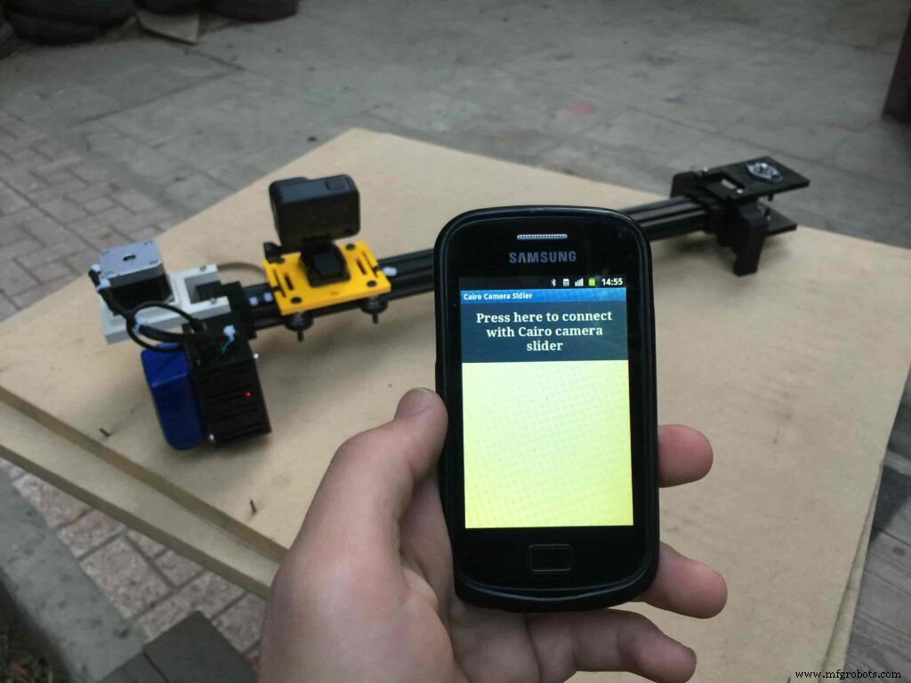
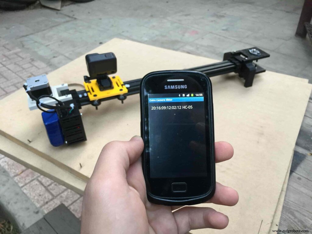
After connecting the 12V power source to the Arduino UNO board that distributes power to the Cairo camera slider Arduino shield as well, turn on the Bluetooth on your mobile, search for new devices, pair with the HC-05 device, and open the mobile app then press on the “Press here to connect with Cairo camera slider” button. It will show up the menu of the paired Bluetooth devices, select the HC-05 Bluetooth device.
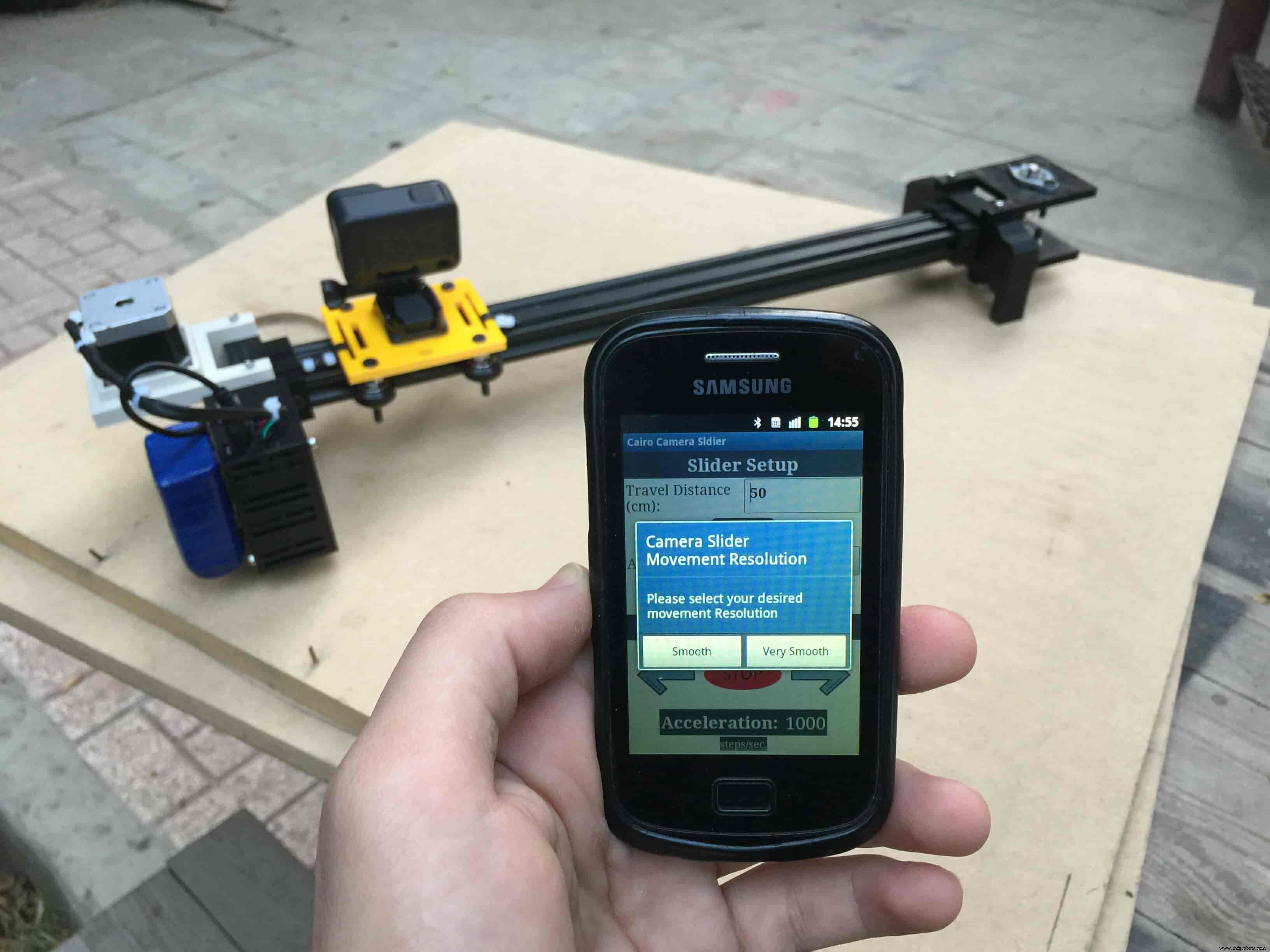
After connecting successfully with the Control board, the mobile app will ask you some questions to set up some parameters. First question will ask you about the micro-step resolution of the stepper motor driver if it’s smooth(1/4 micro-step), or very smooth(1/16 micro-step). select the mode According to the micro-stepping resolution mode that you set the A4988 driver at. If you selected a wrong mode The Cairo camera slider will not work correctly.
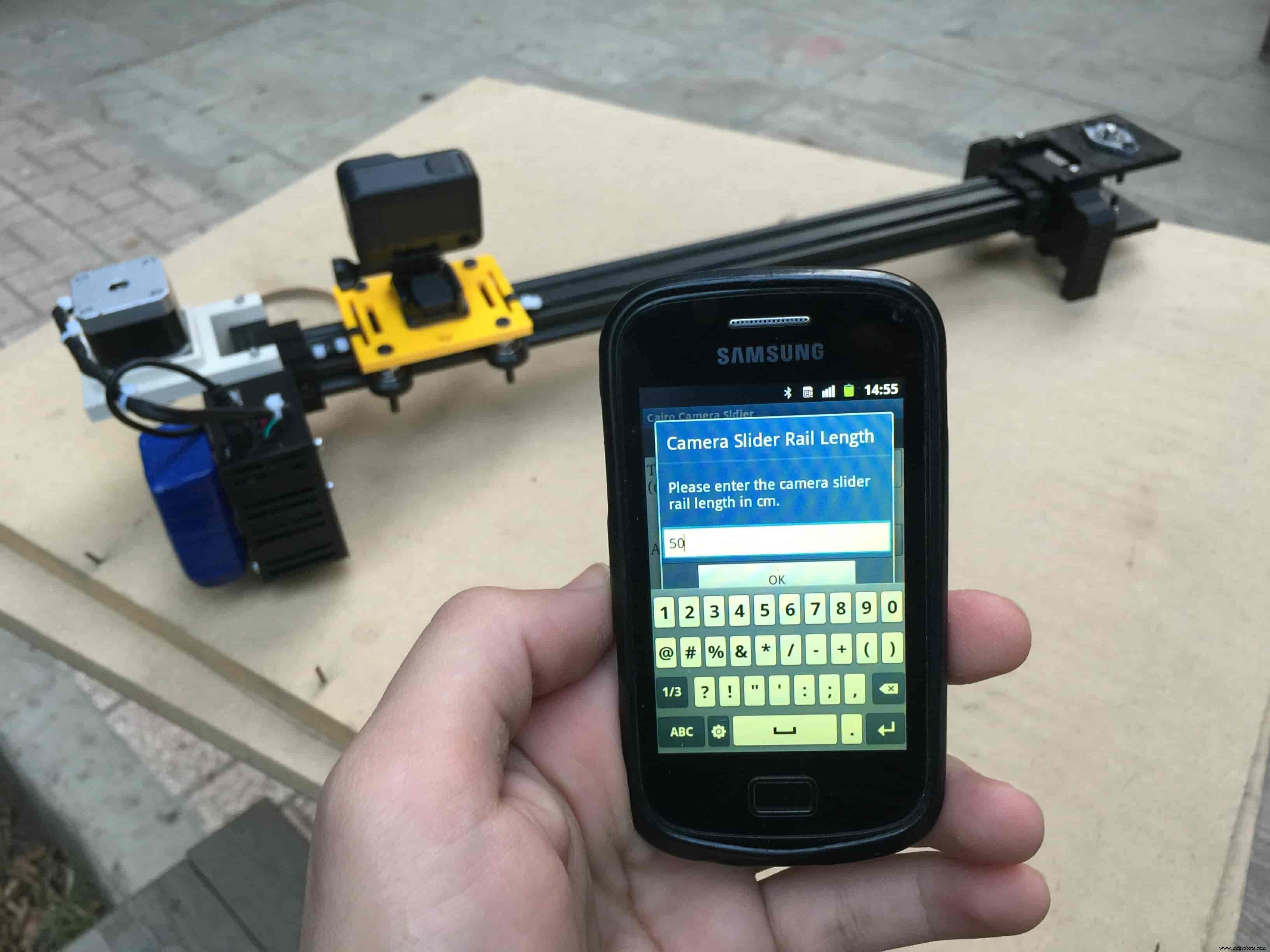
Then, it will ask you about the aluminum rail length that you are using in your camera slider. Enter the distance in CM. in my case I’m using a 50cm rail length.
Lastly, it will ask you about the camera carriage homing position, It’s very important to place the camera carriage on one of the two rail ends, the right end or the left end. In my case, the camera carriage is on the left end. So, I selected the left end homing.
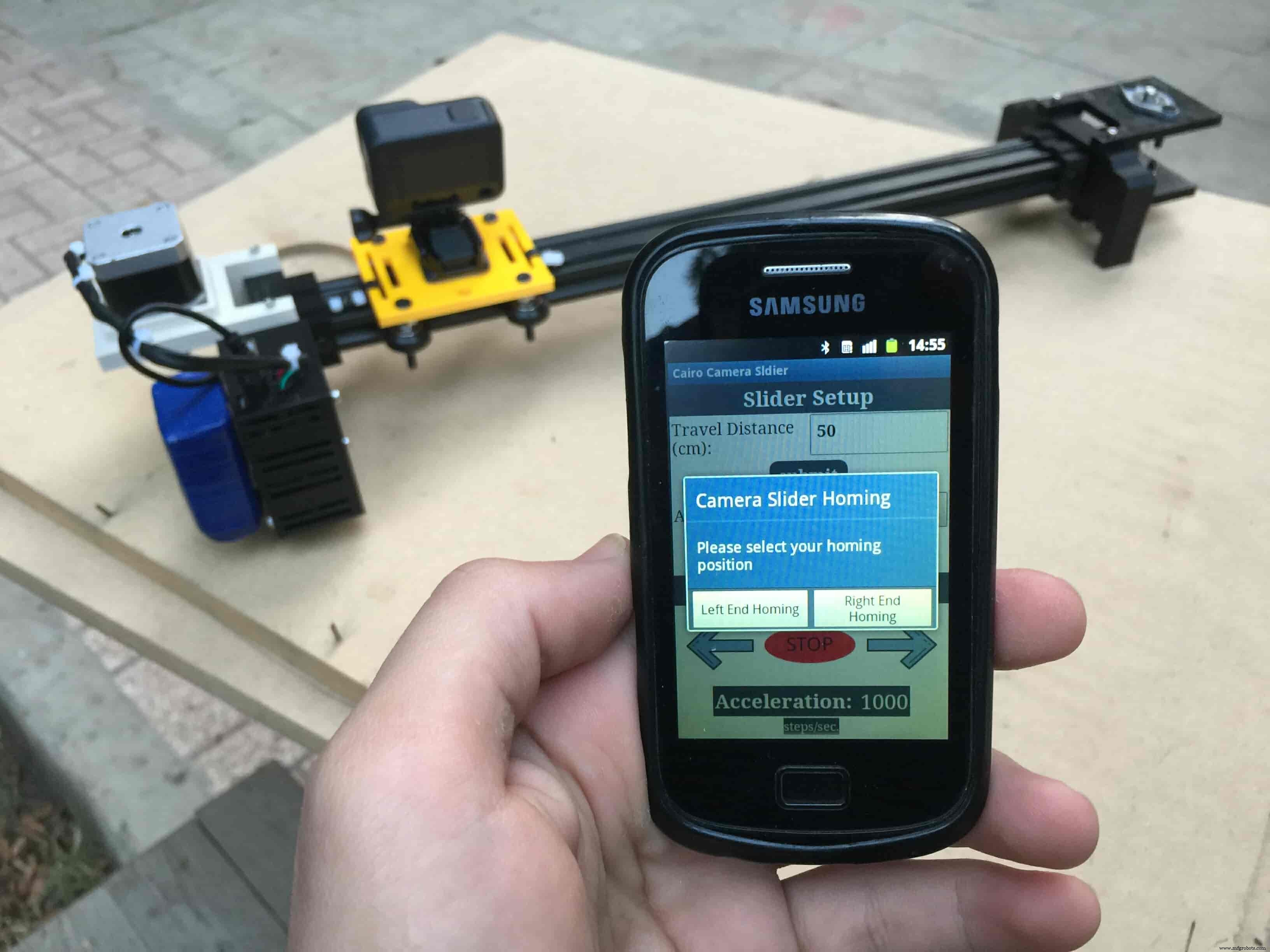
If you started the Cairo camera slider and the camera carriage is on the middle of the rail or not on one of the two rail ends it will cause the carriage to hit the limits when it moves.
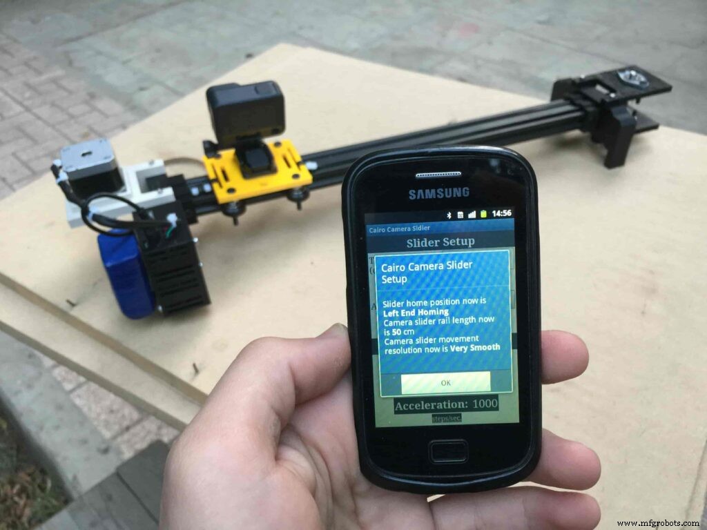
After you finish the set-up process, It will show you the parameters that you have set. And once you click OK, you will be ready to play around with your lovely Cairo camera slider.
Cairo Camera Slider In-Action
/* TODO::Update the arduino program to Make the user able to choose the motor driver micro stepping mode. find and equation that helps to automatically adjust the the "steps" variable value. TODO::update the mobile app to ask the user on the beginning only about the [homing position(done), microstepping mode]. TODO::Update the arduino program to make the code only iterates around the "homing position" &"microstepping mode" only once on the void setup() function. DATA::left arrow button sends --> 1. DATA::right arrow button sends --> 2. DATA::stop button sends --> 3. DATA::rail length (1cm - 1000cm) --> (201 - 1200). DATA::motor acceleration spinner Very High --> 14. DATA::motor acceleration spinner High --> 11 DATA::motor acceleration spinner Medium --> 12 DATA::motor acceleration spinner Low --> 13 DATA::motor acceleration spinner Very Low --> 15 DATA::motor speed slider (1 step/sec. - 4000 step/sec.) --> (5001 - 9000). DATA::delay start checkbox is true --> 7. DATA::delay start checkbox is false --> 8. DATA::left end homing --> 16. DATA::right end homing --> 17. DATA::Smooth movement Type --> 18. DATA::Very Smooth movement Type --> 19. 1301 --> 2300*/#include#include #define stepPin 2#define dirPin 3bool homingPositionFlag =false;int startupSetupFlag =0;bool delayedStart =false;int incomingData =0;int movementDistance =50;long steps =0; //50cm rail by default @1/8 microstepping.int microStepResolution =0; //4 or 16long railLength =0;int sliderSpeed =10;AccelStepper stepper(AccelStepper::DRIVER, stepPin, dirPin); //create an object. the pin "2" is the step pin, "3" is the direction pin.void setup() { pinMode(stepPin, OUTPUT); pinMode(dirPin, OUTPUT); Serial.begin(9600); stepper.setMaxSpeed(10.00); //The fastest motor speed that can be reliably supported is about 4000 steps per second at a clock frequency of 16 MHz on Arduino such as Uno stepper.setAcceleration(500.00); //1600 (40%) (Medium Acceleration rate) while (startupSetupFlag <3) { if (Serial.available()> 1) { unsigned int dataOne =Serial.read(); unsigned int dataOne1 =Serial.read(); unsigned int incomingData =(dataOne1 * 256) + dataOne; //**************************************************************Motor Homing Part************************************************** if (incomingData ==16) { //left end homing position. stepper.setCurrentPosition(steps); homingPositionFlag =false; startupSetupFlag++; } else if (incomingData ==17) { //right end homing position. stepper.setCurrentPosition(-(steps)); homingPositionFlag =true; startupSetupFlag++; } //**************************************************************microstep resolution Part************************************************** if (incomingData ==18) { microStepResolution =4; //50cm rail length @1/4 microstep resolution. startupSetupFlag++; } else if (incomingData ==19) { microStepResolution =16; //50cm rail length @1/16 microstep resolution. startupSetupFlag++; } if (incomingData>=1301 &&incomingData <=2300) { railLength =incomingData - 1300; //from raw data to cm. if (microStepResolution ==4) { steps =((6100L * railLength) / 50L); startupSetupFlag++; } else if (microStepResolution ==16) { steps =((25000L * railLength) / 50L); startupSetupFlag++; } } } //Serial.println(startupSetupFlag); } /* * *********** *********** **********For Debugging Purposes* *********** *********** ********** Serial.print("rail length:"); Serial.print(railLength); Serial.print(" number of steps:"); Serial.print(steps); Serial.print(" Homing position:"); Serial.print(stepper.currentPosition()); Serial.print(" microstep resolution:"); Serial.println(microStepResolution);*/}void loop() { if (Serial.available()> 1) { unsigned int dataOne =Serial.read(); unsigned int dataOne1 =Serial.read(); unsigned int incomingData =(dataOne1 * 256) + dataOne; //Serial.print("raw data:"); //Serial.println(incomingData); //**************************************************************Motor Control Part************************************************** if (incomingData ==1 &&stepper.isRunning() ==false &&stepper.currentPosition() !=6050 &&homingPositionFlag ==true) { if (delayedStart ==true) { //use millis to delay 15 seconds. delay(15000); //wait 15 seconds. } stepper.setCurrentPosition(0); stepper.moveTo(steps); //from end to end (@ 1/4 step). homingPositionFlag =false; /*Serial.print("rail length:"); Serial.print(railLength); Serial.print(" number of steps:"); Serial.print(steps); Serial.print(" Homing position:"); Serial.print(stepper.currentPosition()); Serial.print(" microstep resolution:"); Serial.println(microStepResolution);*/ } else if (incomingData ==2 &&stepper.isRunning() ==false &&stepper.currentPosition() !=-6050 &&homingPositionFlag ==false) { if (delayedStart ==true) { //use millis to delay 15 seconds. delay(15000); //wait 15 seconds. } stepper.setCurrentPosition(0); stepper.moveTo(-(steps)); //from end to end (@ 1/4 step). homingPositionFlag =true; /*Serial.print("rail length:"); Serial.print(railLength); Serial.print(" number of steps:"); Serial.print(steps); Serial.print(" Homing position:"); Serial.print(stepper.currentPosition()); Serial.print(" microstep resolution:"); Serial.println(microStepResolution);*/ } else if (incomingData ==3 &&stepper.isRunning() ==true) { homing(); } //**************************************************************Set Max. Speed Part************************************************** else if (incomingData>=5001 &&incomingData <=9000) { sliderSpeed =incomingData - 5000; stepper.setMaxSpeed(sliderSpeed); } //**************************************************************Set Delayed Start Part************************************************** else if (incomingData ==7) { //delayed start (15 seconds) is checked "true" delayedStart =true; } else if (incomingData ==8) { //delayed start (15 seconds) is not checked "false" delayedStart =false; } //**************************************************************Set movement distance Part************************************************** else if (incomingData>=201 &&incomingData <=1200) { //convertin from rail length into number of steps. (upto 10 meters) movementDistance =incomingData - 200; //from raw data to cm. if (microStepResolution ==4) { steps =((6100L * movementDistance) / 50L); } else if (microStepResolution ==16) { steps =((25000L * movementDistance) / 50L); } /*Serial.print("rail length:"); Serial.print(movementDistance); Serial.print(" number of steps:"); Serial.println(steps);*/ } //**************************************************************Set Acceleration Part************************************************** else if (incomingData ==11 &&stepper.isRunning() ==false) { //HIGH stepper.setAcceleration(3000); } else if (incomingData ==12 &&stepper.isRunning() ==false) { //Medium stepper.setAcceleration(1000); } else if (incomingData ==13 &&stepper.isRunning() ==false) { //Low stepper.setAcceleration(500); } else if (incomingData ==14 &&stepper.isRunning() ==false) { //Very High stepper.setAcceleration(4000); } else if (incomingData ==15 &&stepper.isRunning() ==false) { //Very Low stepper.setAcceleration(10); } } stepper.run();}void homing() { if (stepper.currentPosition()> 0) { homingPositionFlag =true; } else { homingPositionFlag =false; } stepper.moveTo(0);}

제조공정
구성품 및 소모품 Arduino UNO × 1 커패시터 100μF × 1 LED(일반) × 5 PIR 모션 센서(일반) × 5 저항 220옴 × 5 서보(타워 프로 MG996R) × 1 이 프로젝트 정보 저는 집에 있는 보안 카메라에 대한 문제를 해결하기 위해 이 아이디어를 생각해 냈습니다. 두 방 사이의 벽에 위치한 특정 카메라가 하나 있지만 카메라 소프트웨어에 로그인하여 수동으로 회전하지 않는 한
이 튜토리얼에서는 팬 및 틸트 헤드가 있는 전동 카메라 슬라이더를 만드는 방법을 배웁니다. 이 Arduino 기반 프로젝트는 100% DIY이며 MDF 및 합판과 같은 저렴한 재료로 제작되고 Arduino, 3개의 스테퍼 모터, 일부 버튼 및 맞춤형 설계 PCB에 부착된 조이스틱을 사용하여 제어됩니다. 그럼에도 불구하고 매우 부드러운 카메라 움직임으로 전문가 수준의 영화 같은 장면을 얻을 수 있어 최종 결과는 매우 인상적입니다. 다음 비디오를 보거나 아래에 작성된 튜토리얼을 읽을 수 있습니다. 개요 컨트롤러를 사용하여 수동으로