

제조공정

산업 제조
 |
| × | 1 | |||
| × | 1 | ||||
 |
| × | 1 | |||
 |
| × | 1 | |||
 |
| × | 1 |
| ||||
| ||||
| ||||
| ||||
| ||||
 |
| |||
|
흥미롭지만 복잡한 이 프로젝트는 로봇 구축부터 Linux(라즈베리 파이)의 고급 구성, Android 애플리케이션 구축 및 로봇 제어에 이르기까지 다양한 내용을 다룹니다.
그래서 이것은 일반 프로젝트보다 더 야심차지만 여기에서 몇 가지 아이디어를 검토하거나 전체 프로젝트를 복제함으로써 배울 점이 많을 것이라고 생각합니다.
먼저 플렉시 유리, 플라스틱 시트, 기어박스가 있는 DC 모터 및 다양한 전자 부품을 사용하여 로봇을 만들 것입니다. 이 장치는 두 개의 앞바퀴를 독립적으로 움직일 수 있으며 헤드라이트를 사용할 수 있습니다. 그런 다음 로봇에 전원을 공급하는 라즈베리 파이를 설정하고 프로젝트를 구성하고 다양한 종속성을 설치합니다. 그런 다음 Android 앱을 빌드 및 설치하고 카메라와 Wi-Fi 연결을 사용하여 원격으로 로봇을 제어하는 데 사용할 것입니다.
여기에서 기술과 개념을 탐색합니다. :
개발 플랫폼:Arduino, Raspberry pi, Android
전자 장치:H-브리지, 트랜지스터를 사용하여 큰 부하를 구동하는 적외선 센서
Linux :docker 사용, docker compose, systemctl을 사용하여 서비스 구성, 비디오 스트리밍
프로그래밍:Android 애플리케이션, python, arduino 언어, 직렬 통신, MQTT
1단계:필요한 것
부품:
1. 플렉시 유리 시트
2. 플라스틱 시트(여기서 플렉시 유리 시트를 사용할 수도 있습니다)
3. 접착제
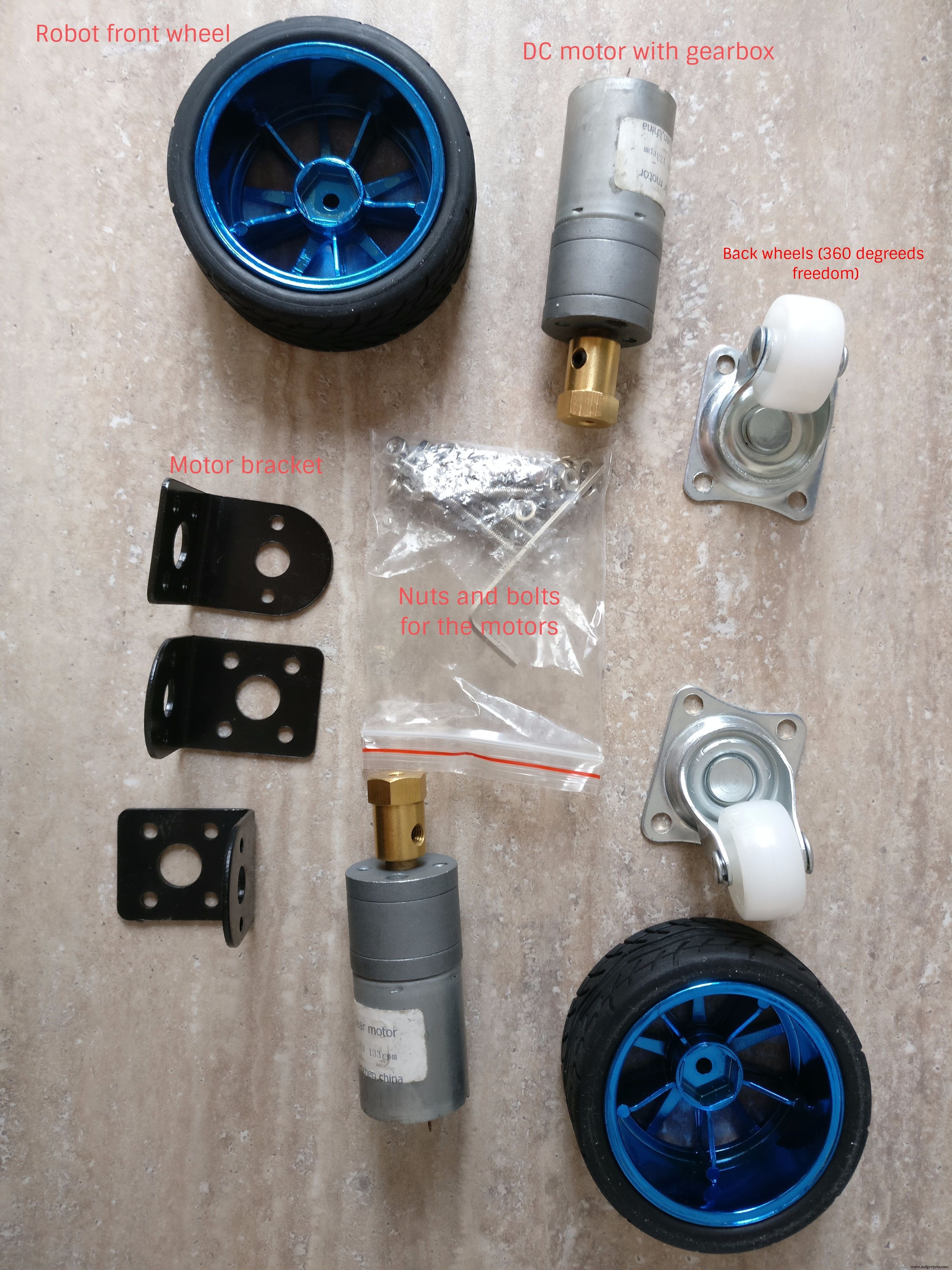
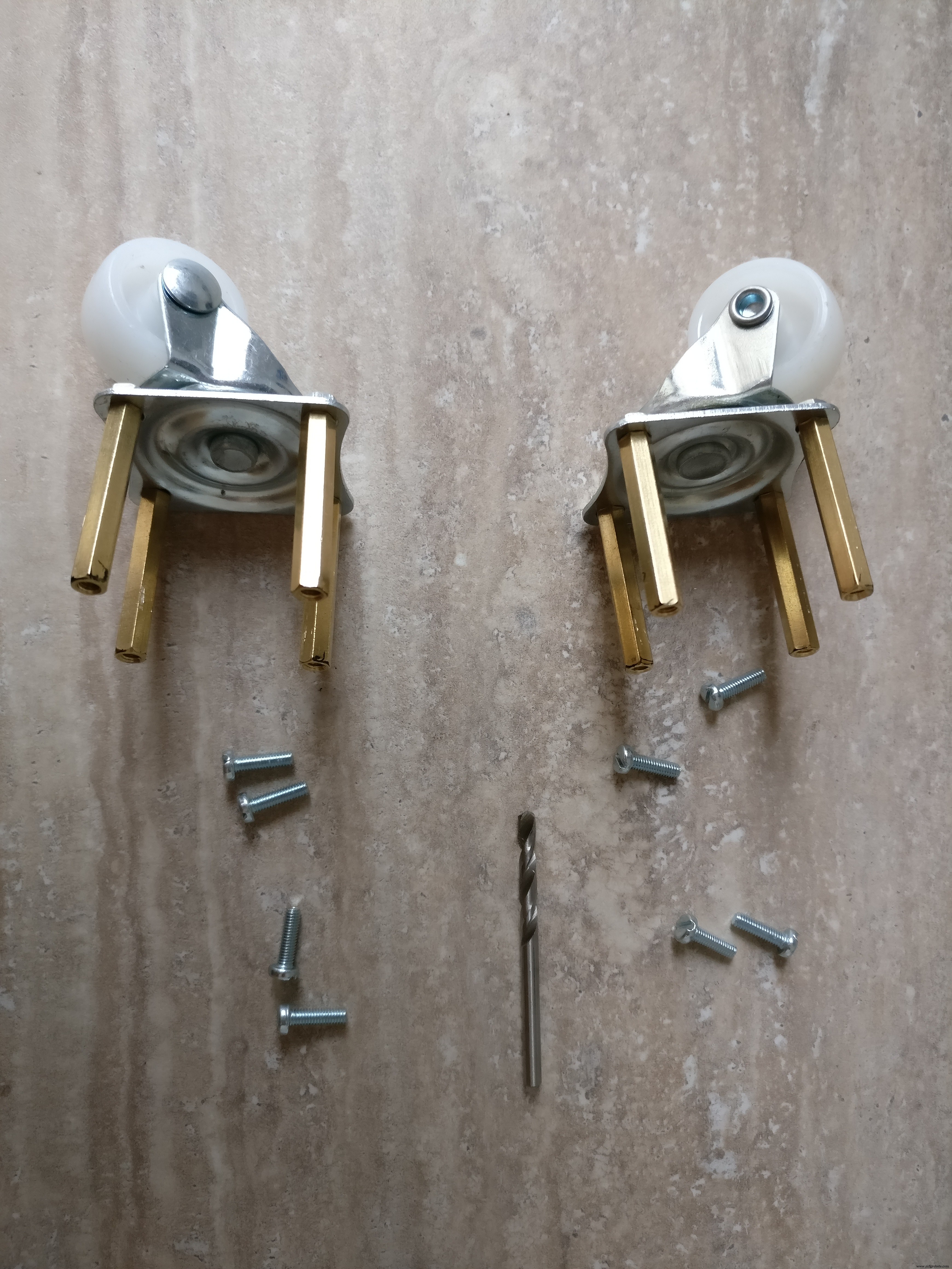
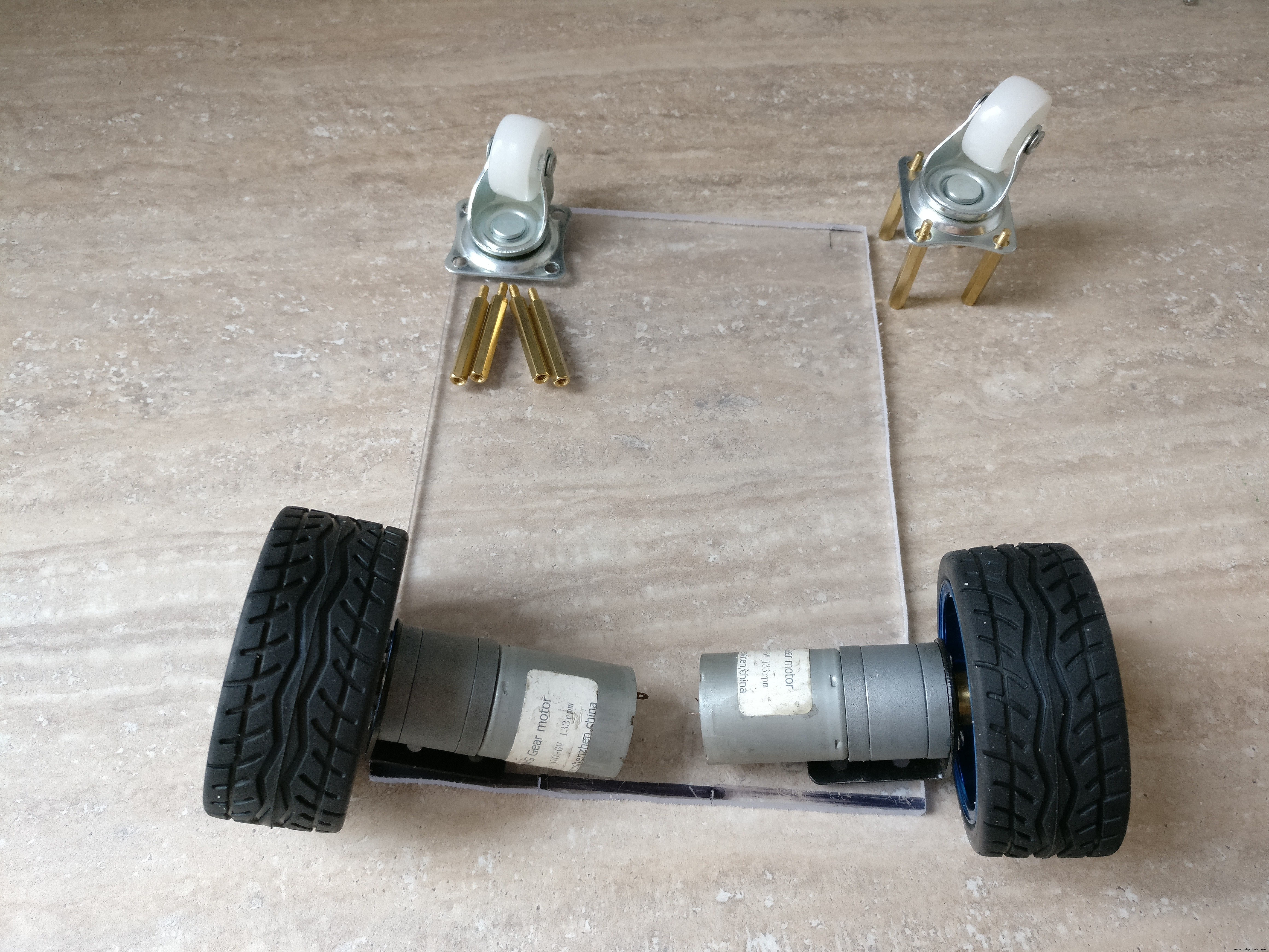
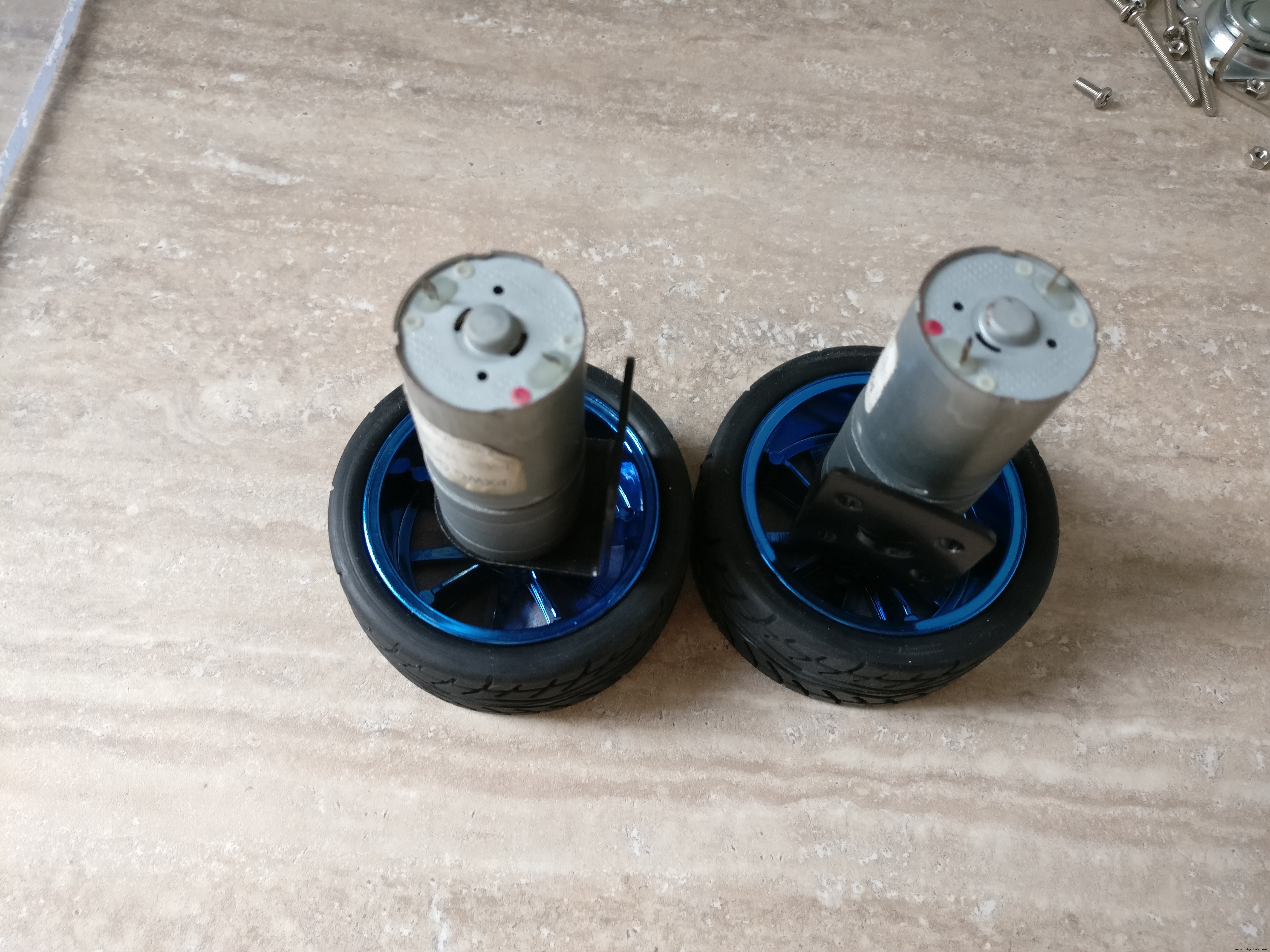
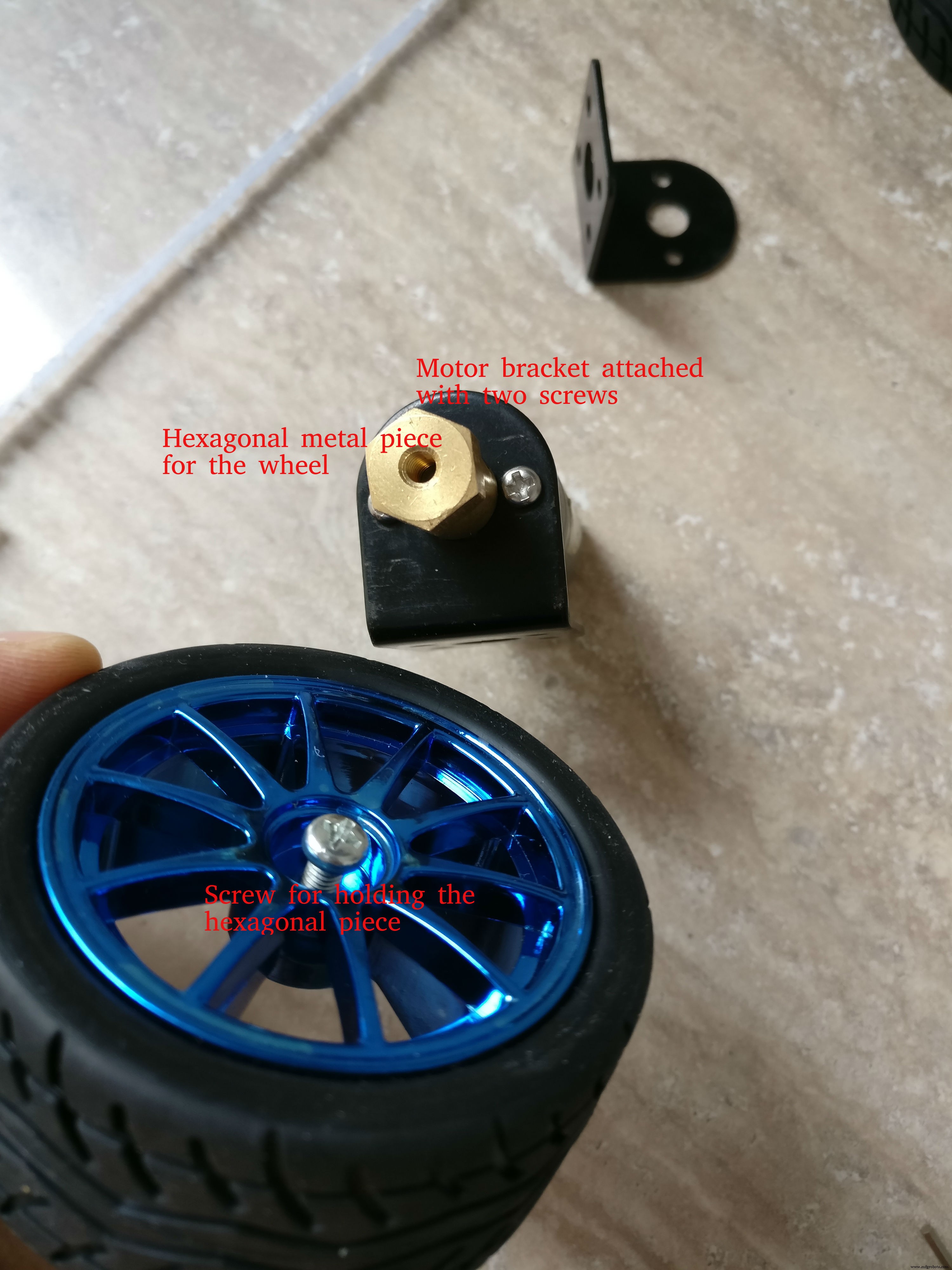
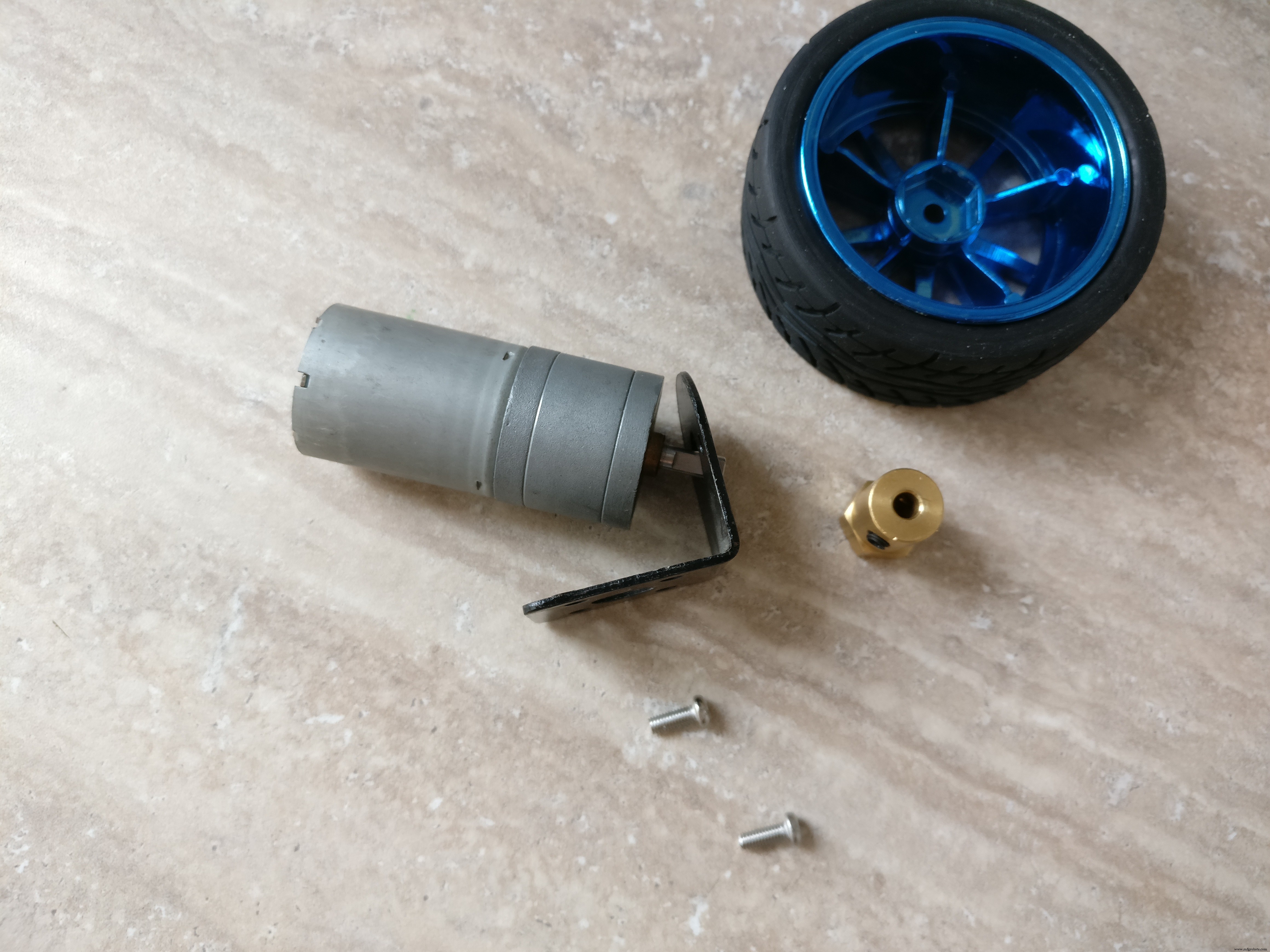
4. 기어 박스 + 브래킷이 있는 타이어 + DC 모터. 작은 너트와 볼트, 육각형 금속 스페이서
6. 2 x 모든 방향성 휠 타이어
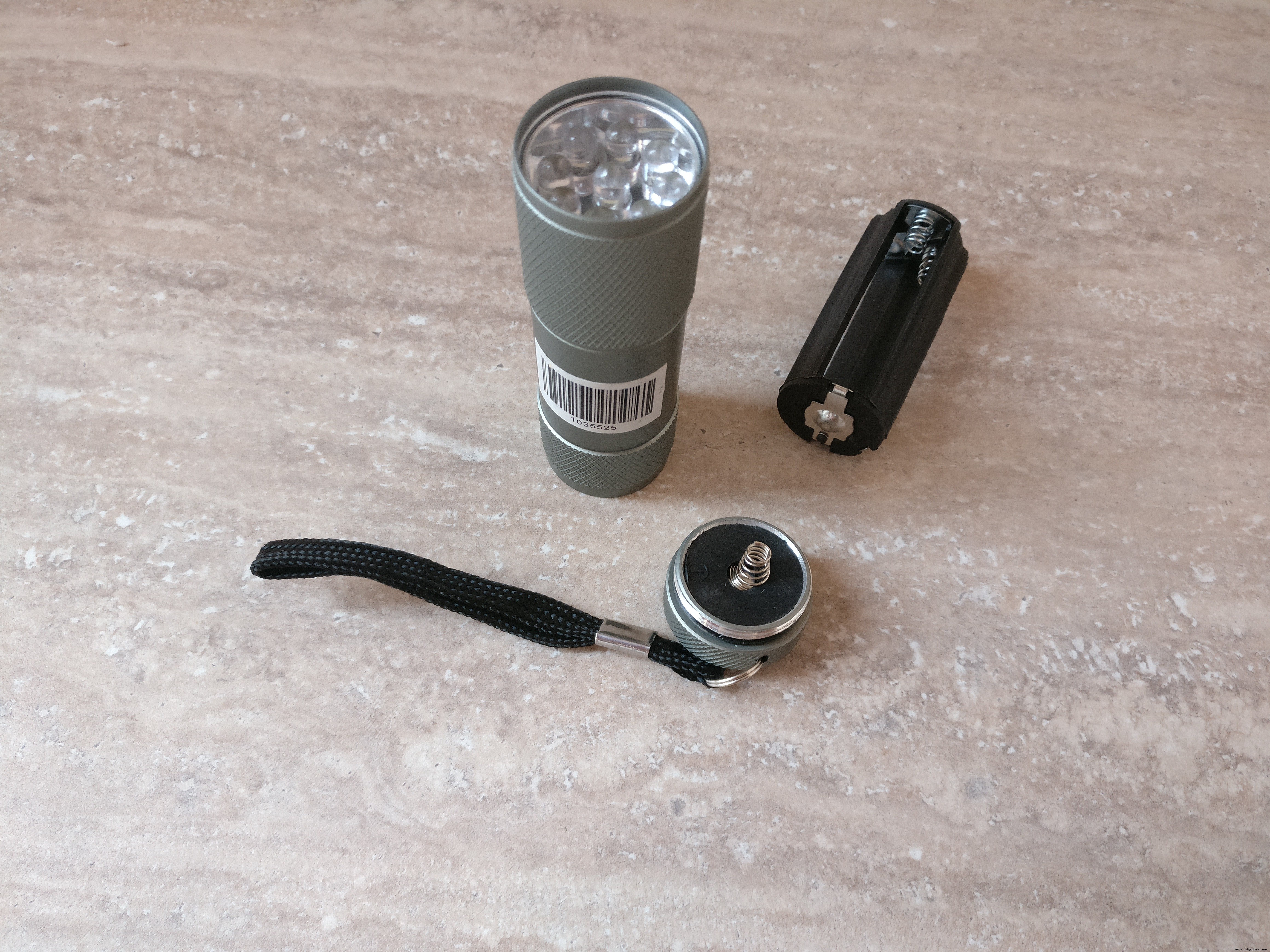
7. 소형 LED 손전등(헤드라이트로 변신)
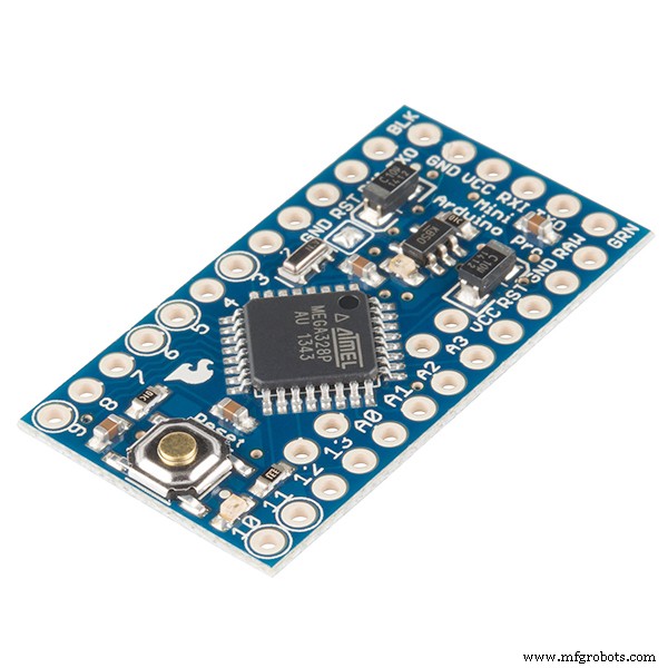
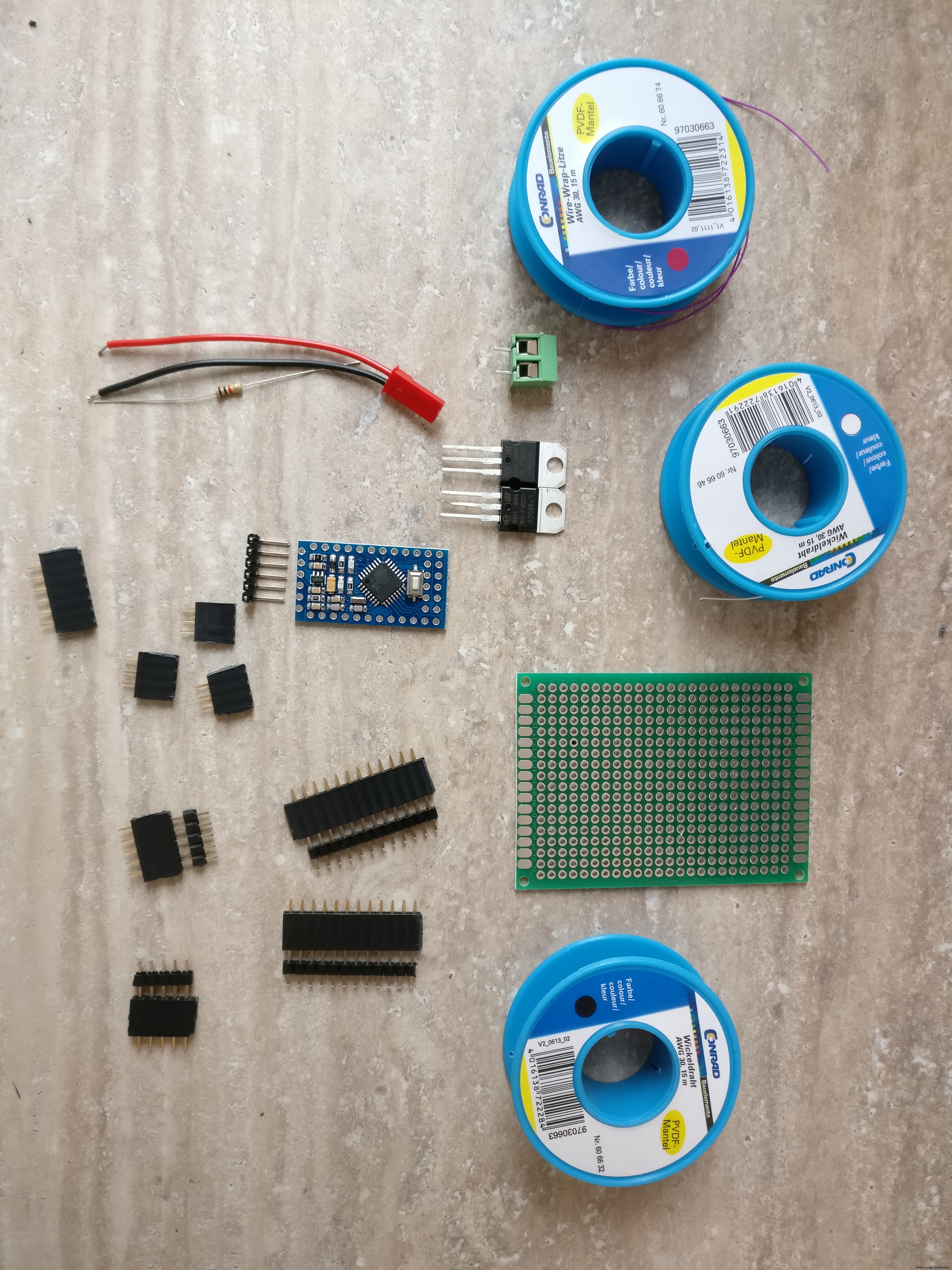
8. 아두이노 프로 미니 328p
9. 2 x 적외선 장애물 센서
10. PCB
11. NPN 트랜지스터(손전등 구동용)
12. L7805CV 5V 레귤레이터
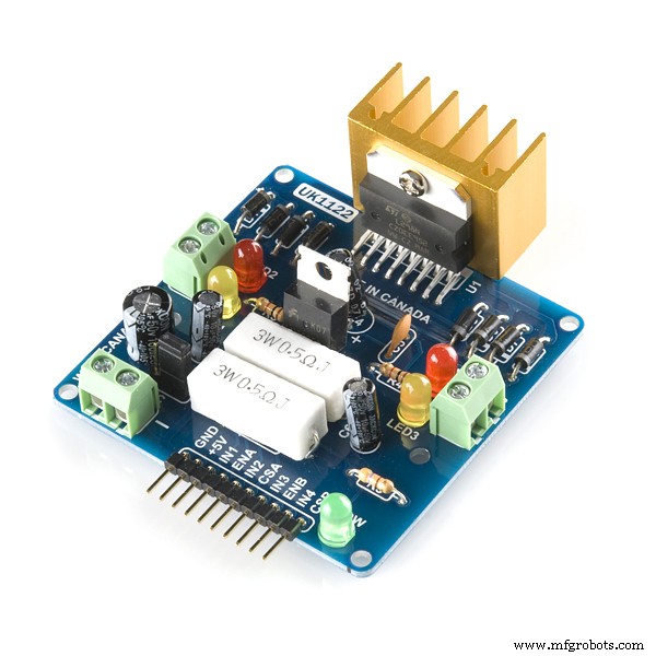
13. L298 H-브릿지
14. 저항기 220옴
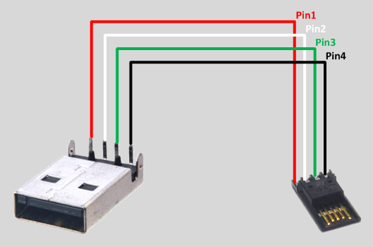
15. 수 USB 커넥터
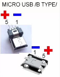
16. 수 마이크로 USB 커넥터
17. 다양한 전선
18. 3v 레귤레이터(arduino와 raspberry pi 간의 통신용)
19. 암수 PCB 커넥터
20. 온/오프 스위치
21. XT-60 암 LiPo 커넥터
22. XT-60 커넥터가 있는 2S 1300mAh LiPo 배터리
23. 5v 배터리 팩
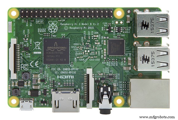
24. 라즈베리 파이 3
25. 라즈베리 파이 카드
26. 라즈베리파이 케이스
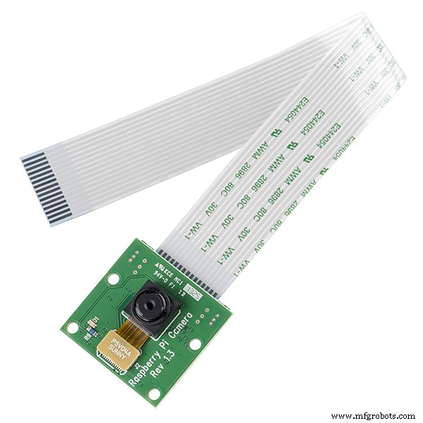
27. 라즈베리파이 카메라
도구: 1. arduino pro mini를 프로그래밍하기 위한 USB-직렬 FTDI 어댑터 FT232RL
2. 아두이노 IDE
3. 드릴
4. 가는 톱날
5. 드라이버
6. 납땜 인두
7. 와이어 커터
스킬:
1. 납땜, 이 튜토리얼을 확인하세요
2. 기본 arduino 프로그래밍, 이 튜토리얼이 유용할 수 있습니다.
3. 리눅스 서비스 설정, 패키지 설치
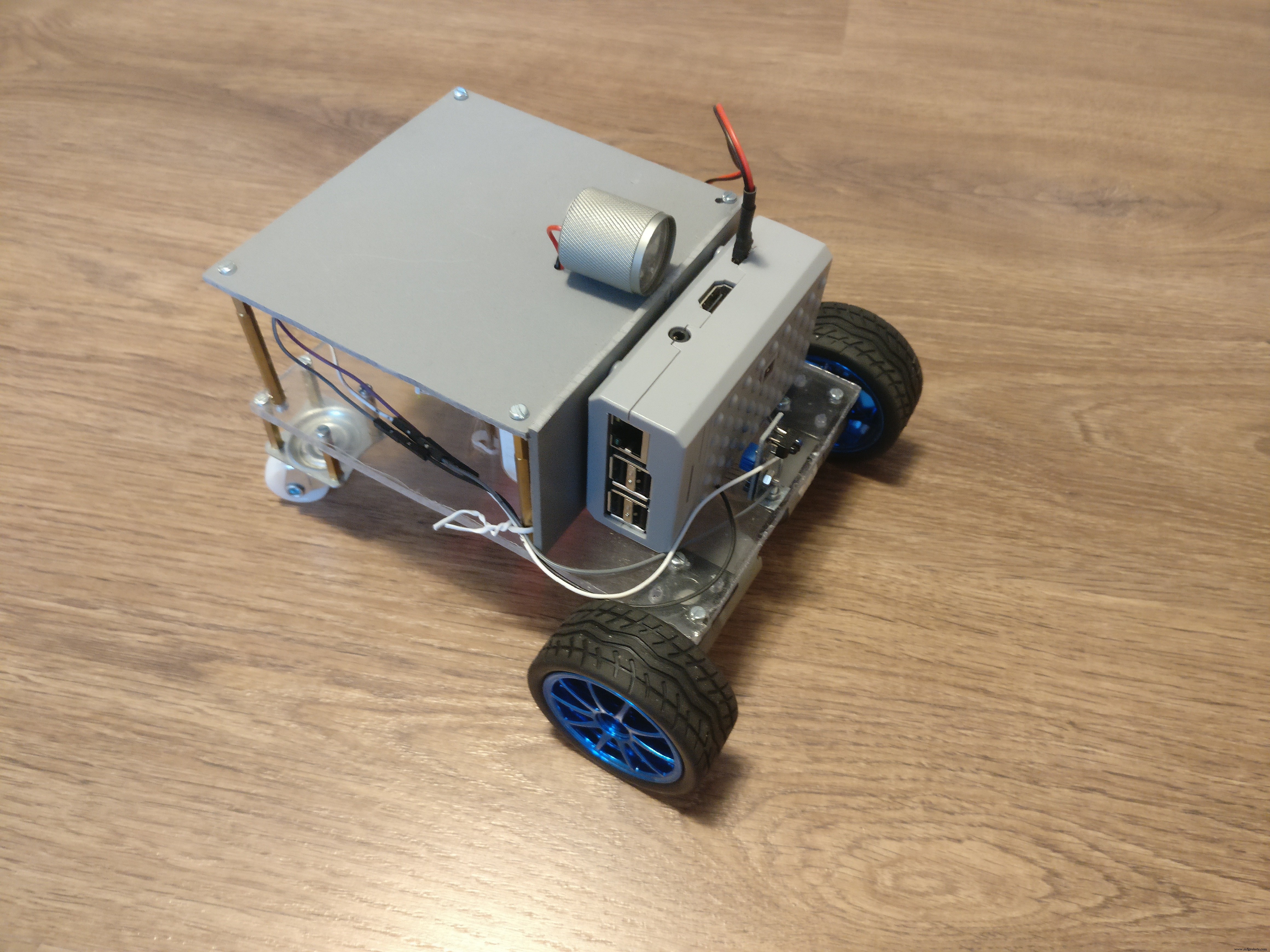
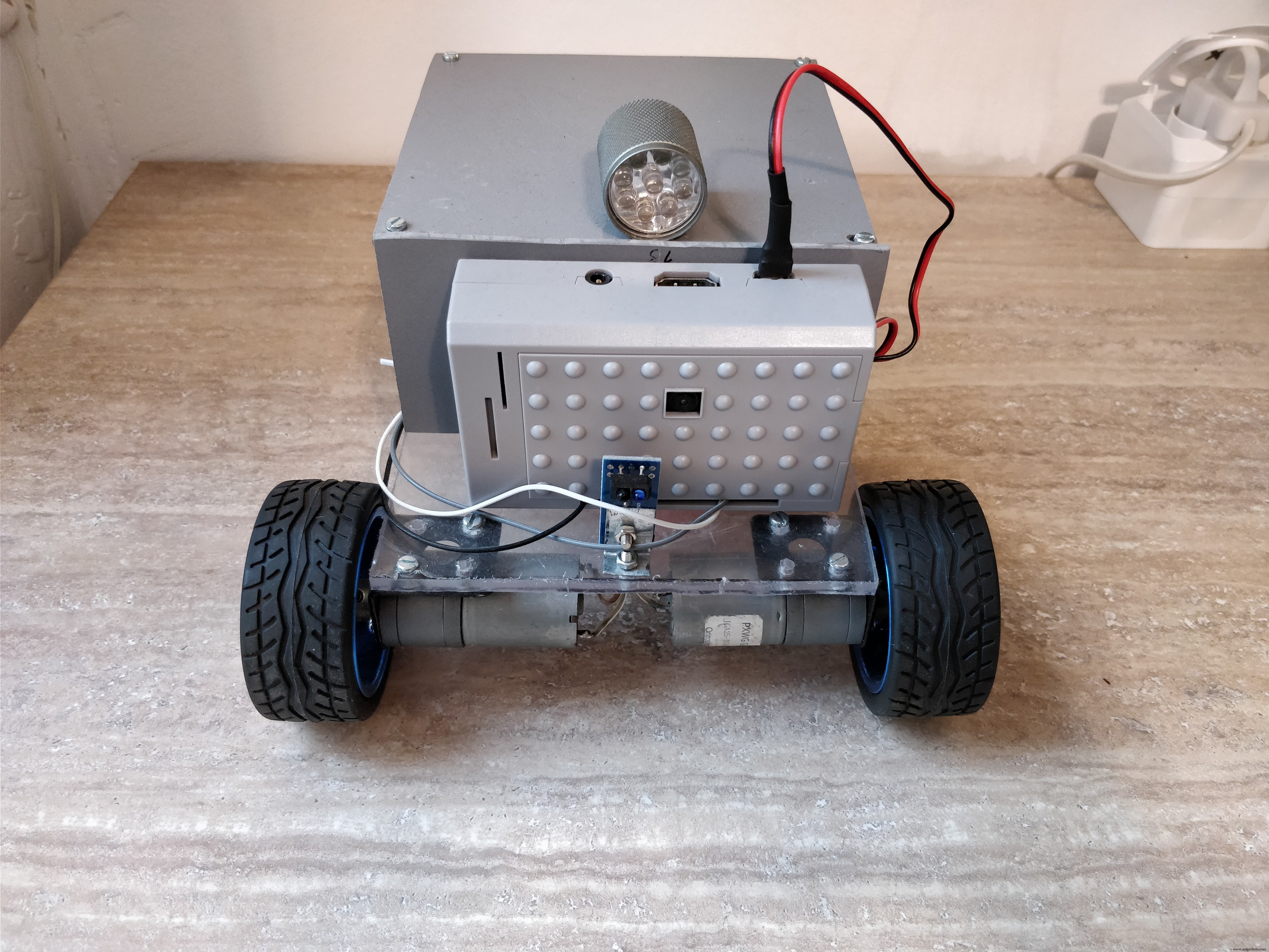
2단계:로봇 플랫폼 구축
로봇 다음 사양으로 빌드할 예정입니다. :
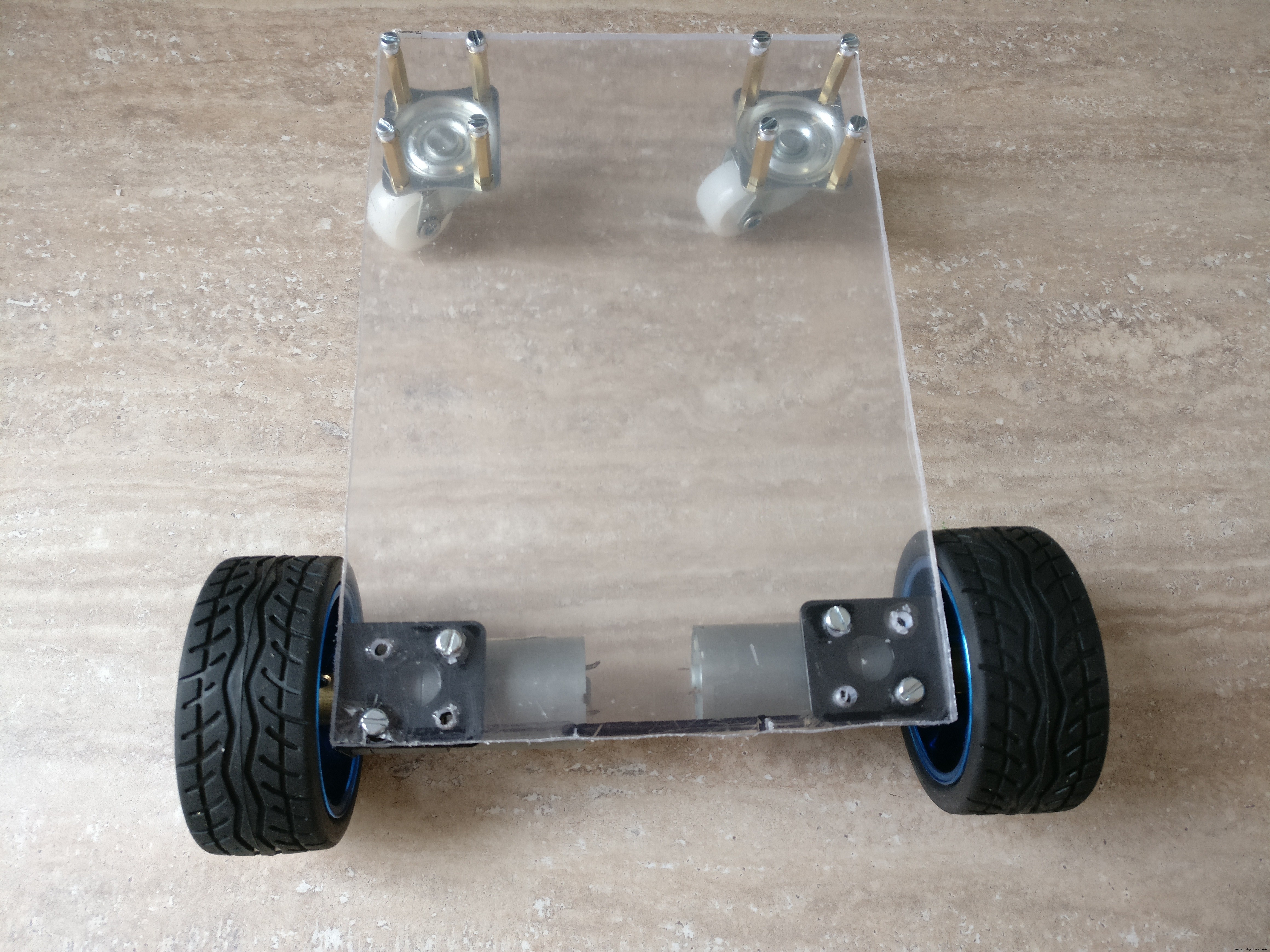
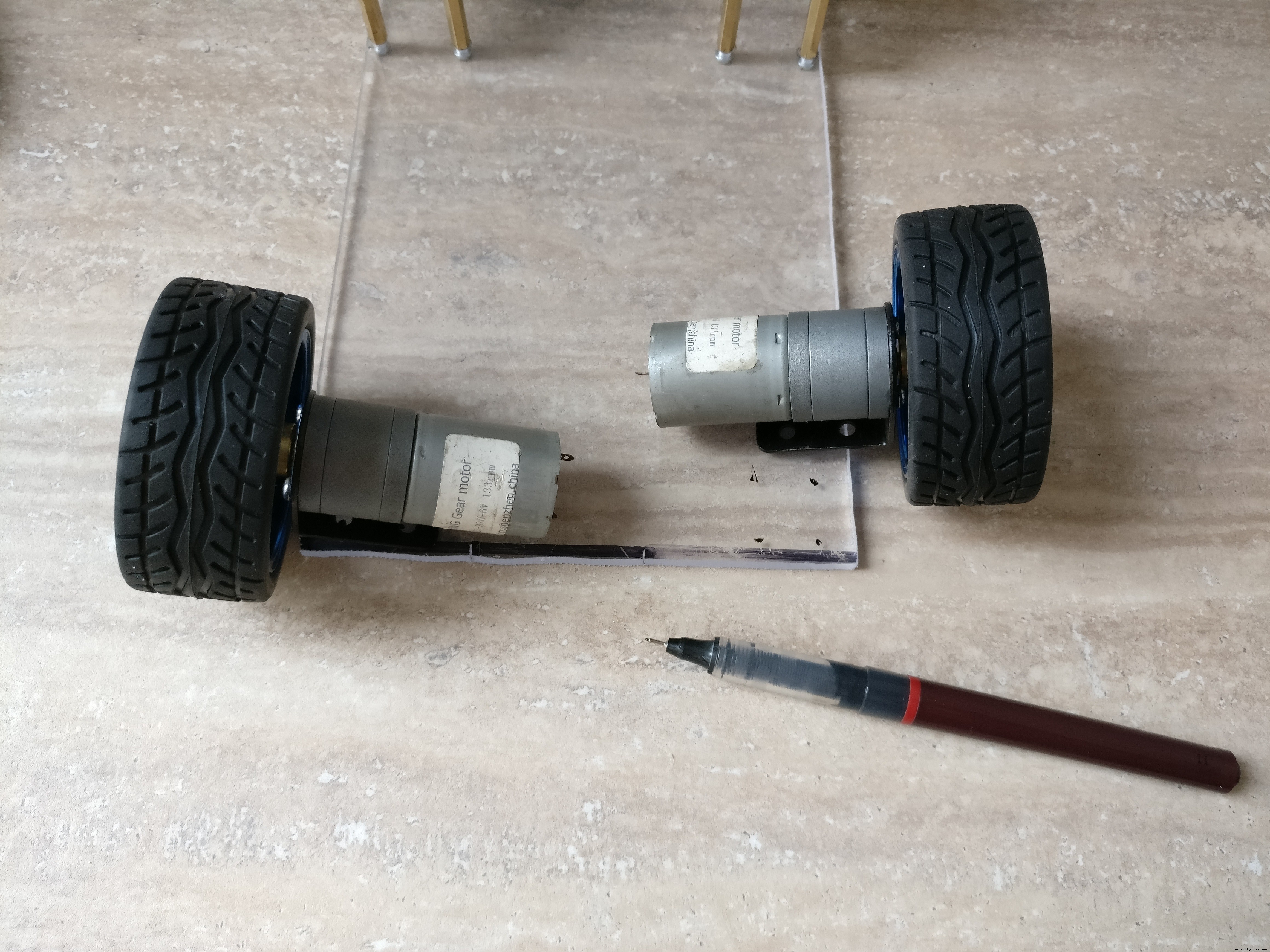
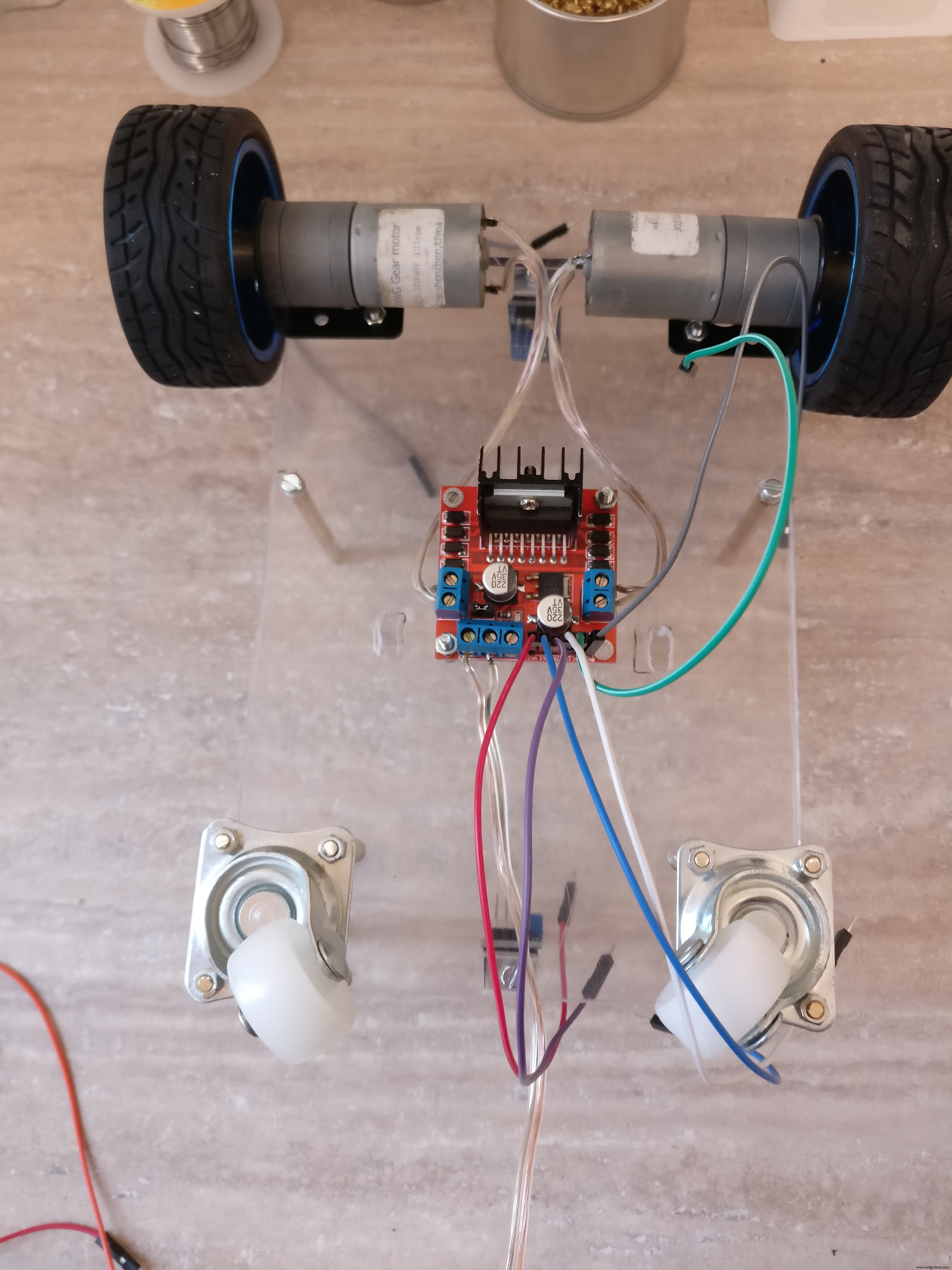
- 두 개의 개별 DC 모터에 의해 앞바퀴에 견인력이 있습니다.
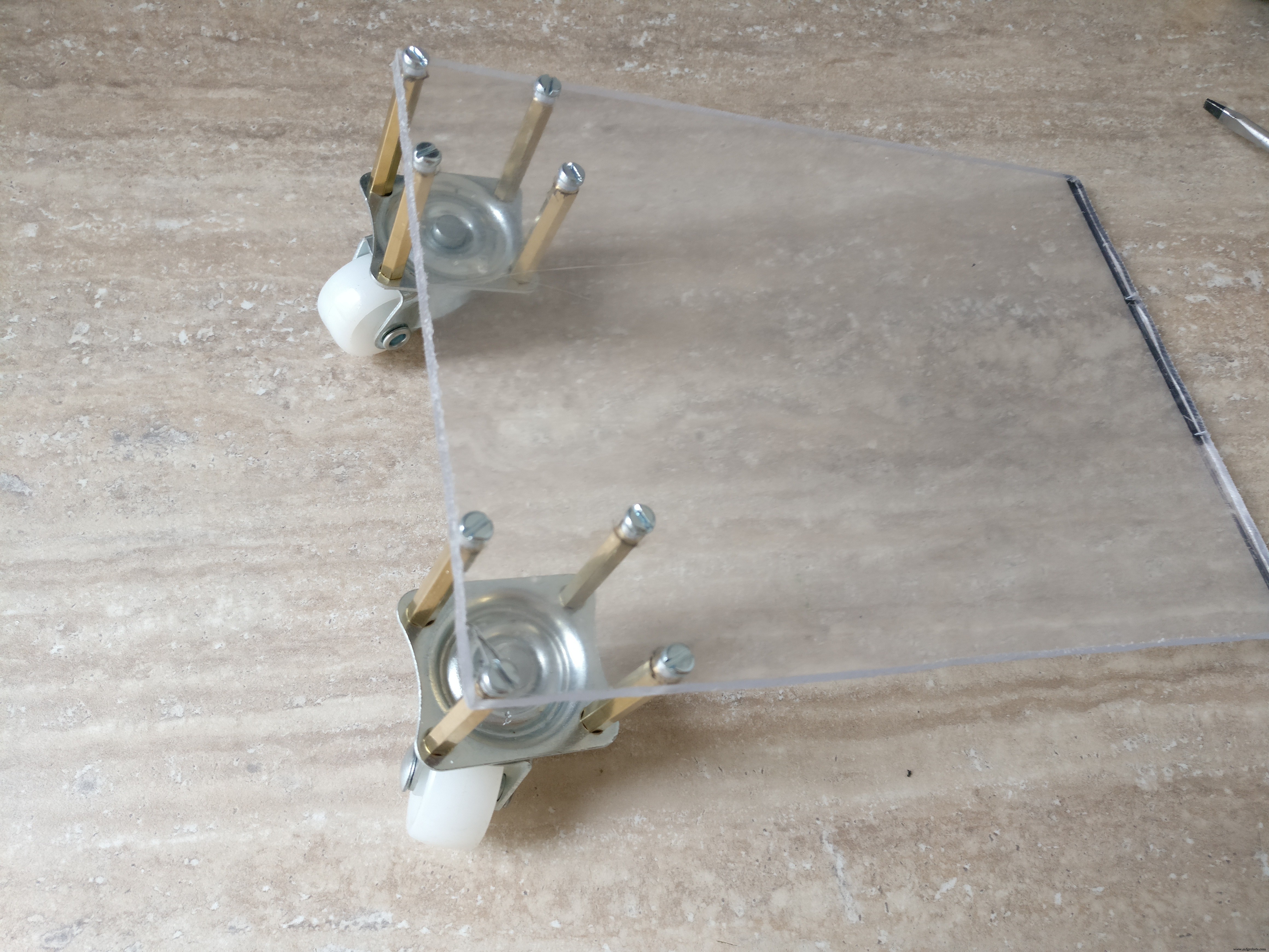
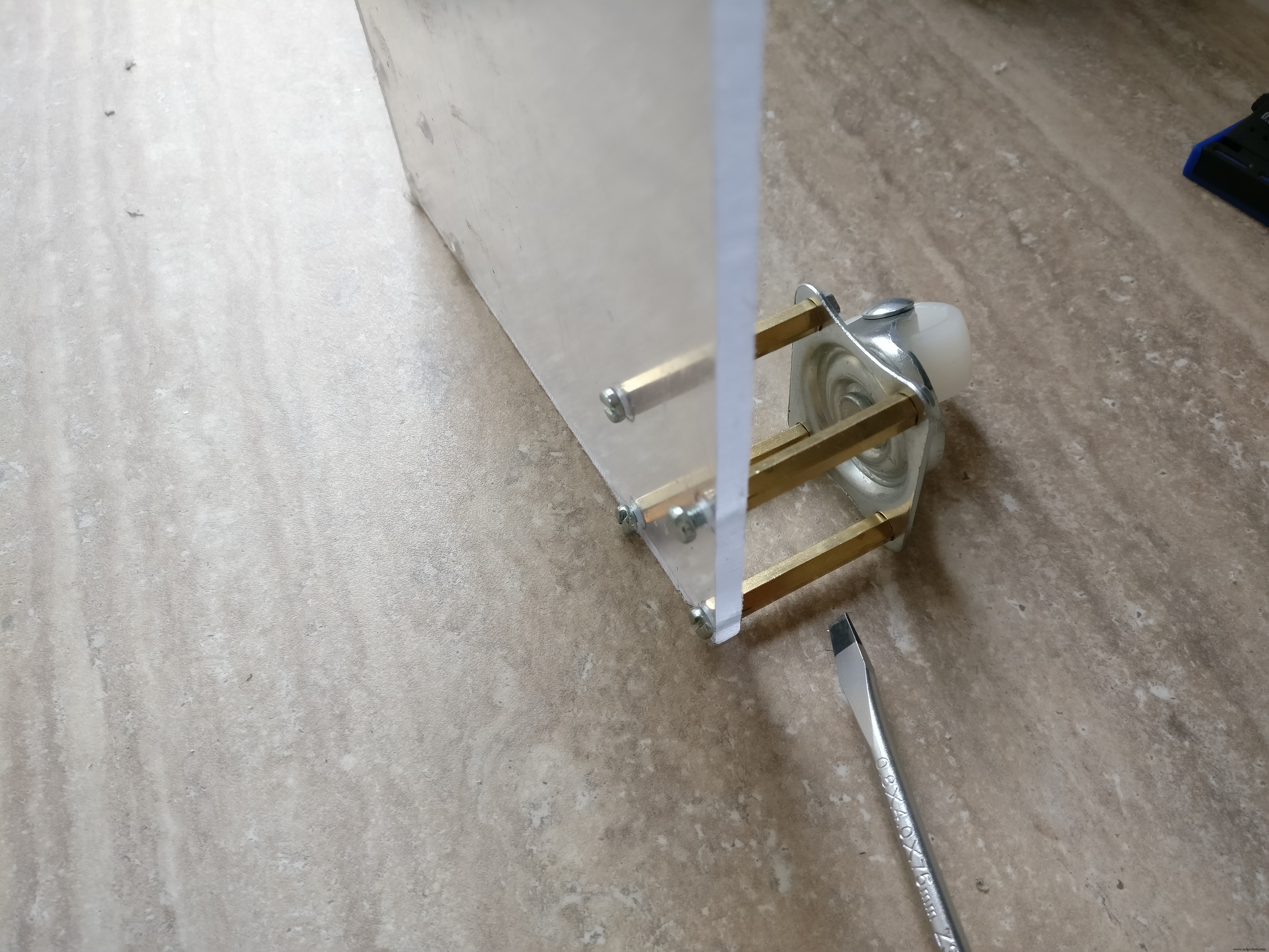
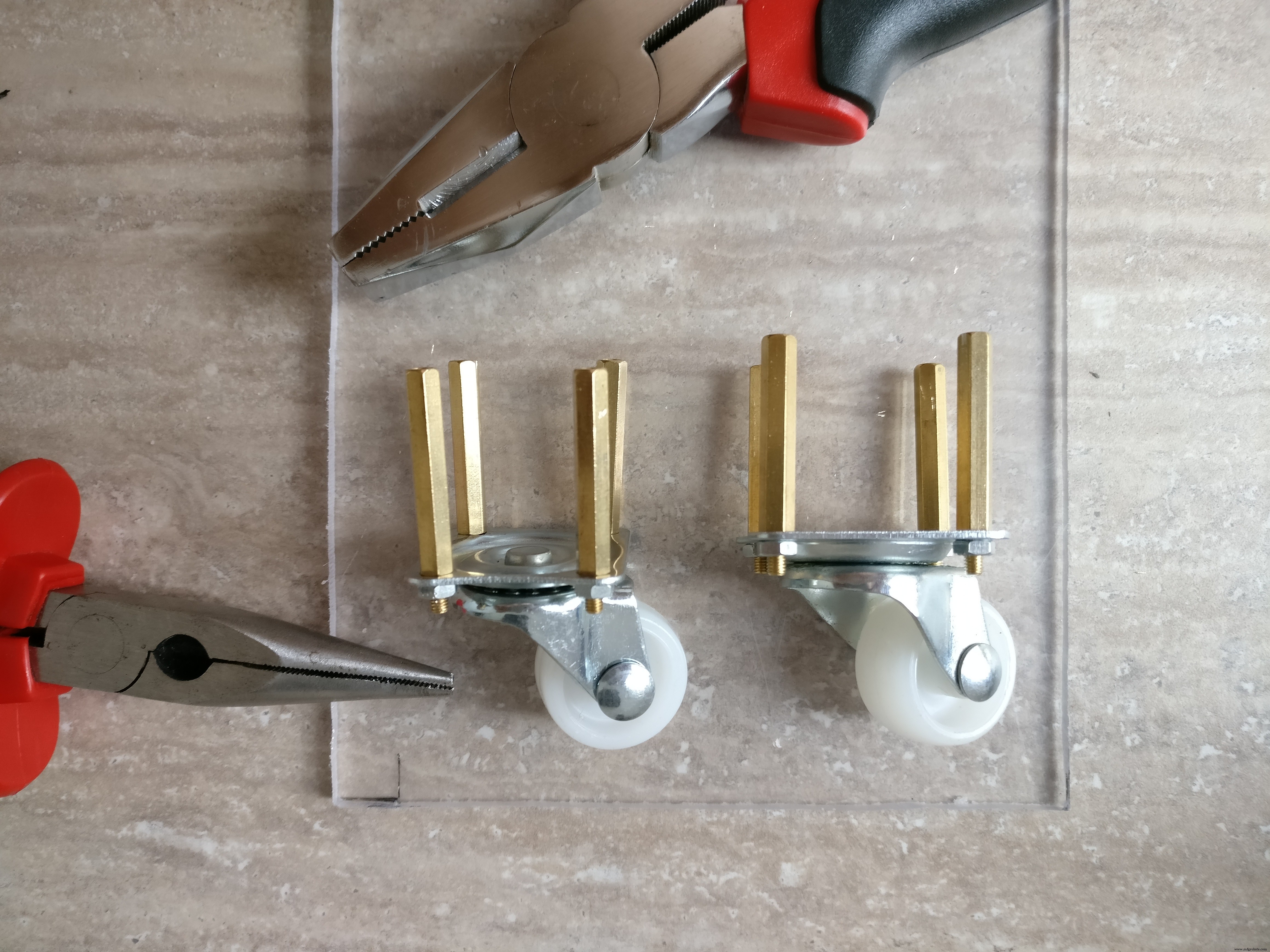
- 뒷바퀴는 360도 모든 방향으로 움직일 수 있어야 합니다.
- 앞바퀴의 속도를 변경하여 방향을 제어하므로 별도의 방향 메커니즘이 필요하지 않으며 로봇도 제자리에서 회전할 수 있습니다.
- 상단에 조명이 있습니다.
- 전자 제품, 배터리 및 카메라가 있는 라즈베리 파이 케이스를 위한 충분한 공간이 있어야 합니다.
- 작은 장애물을 극복하려면 몇 cm의 지상고가 필요합니다.
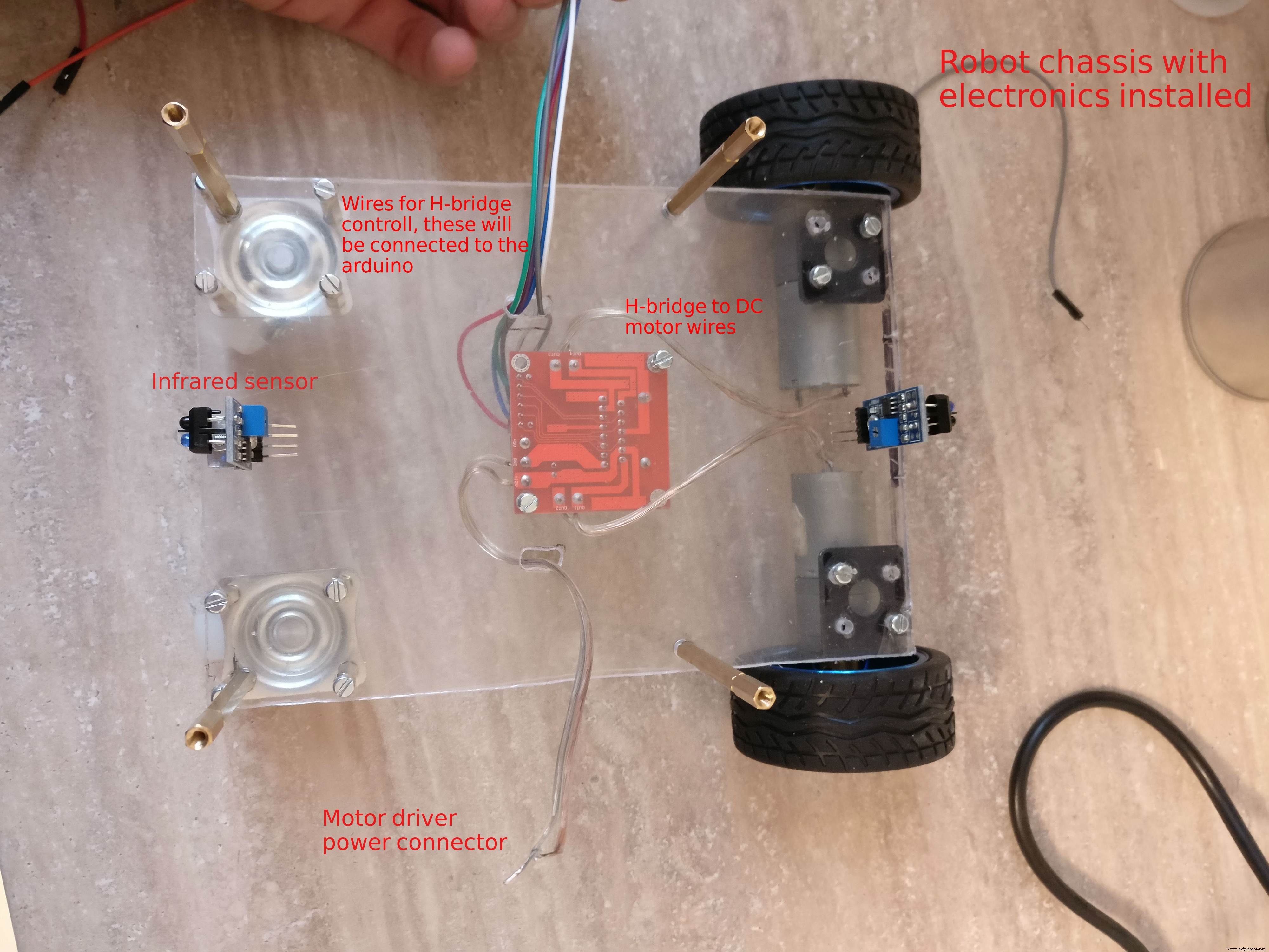
중요한 세부정보와 제작 팁은 이미지를 확인하는 것을 잊지 마세요.
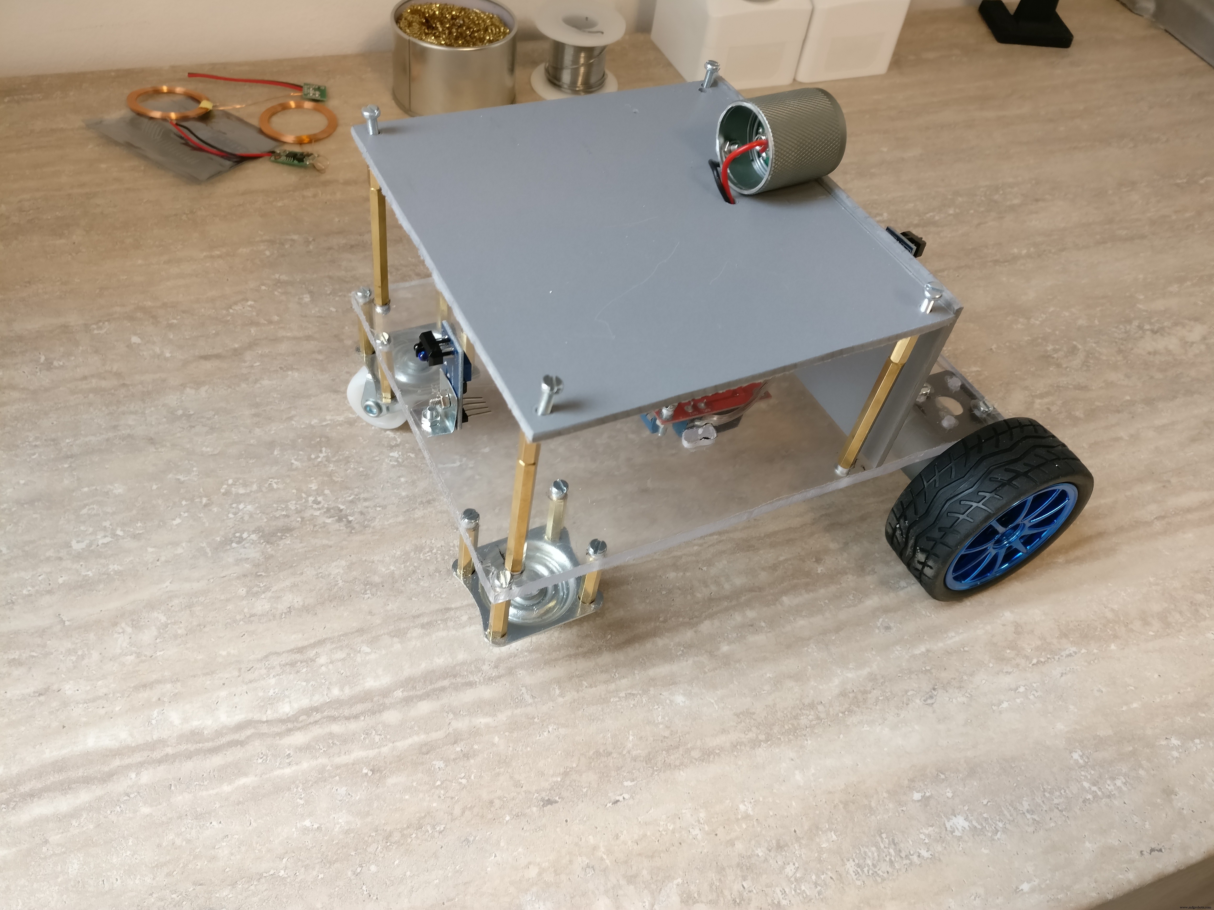

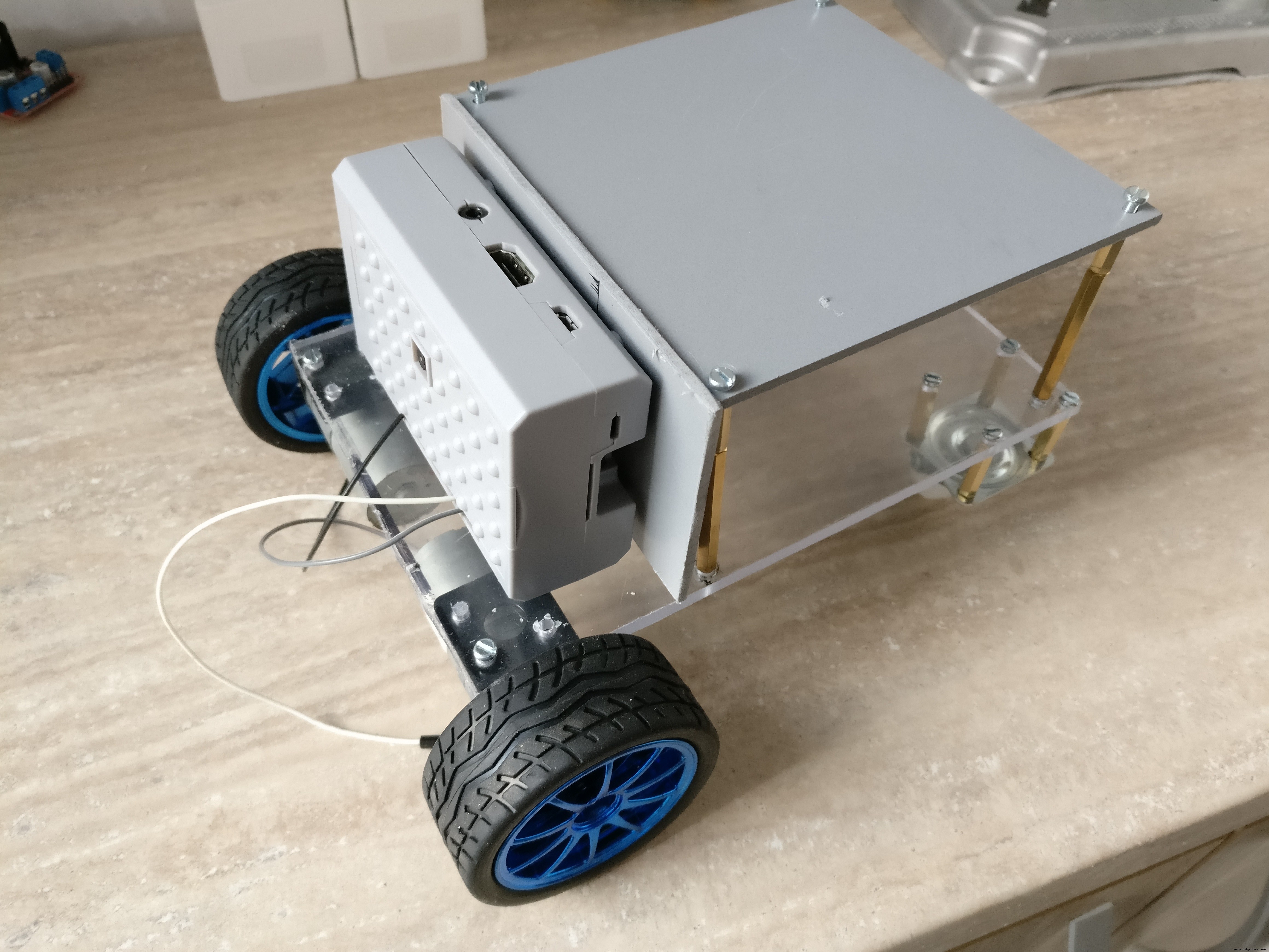


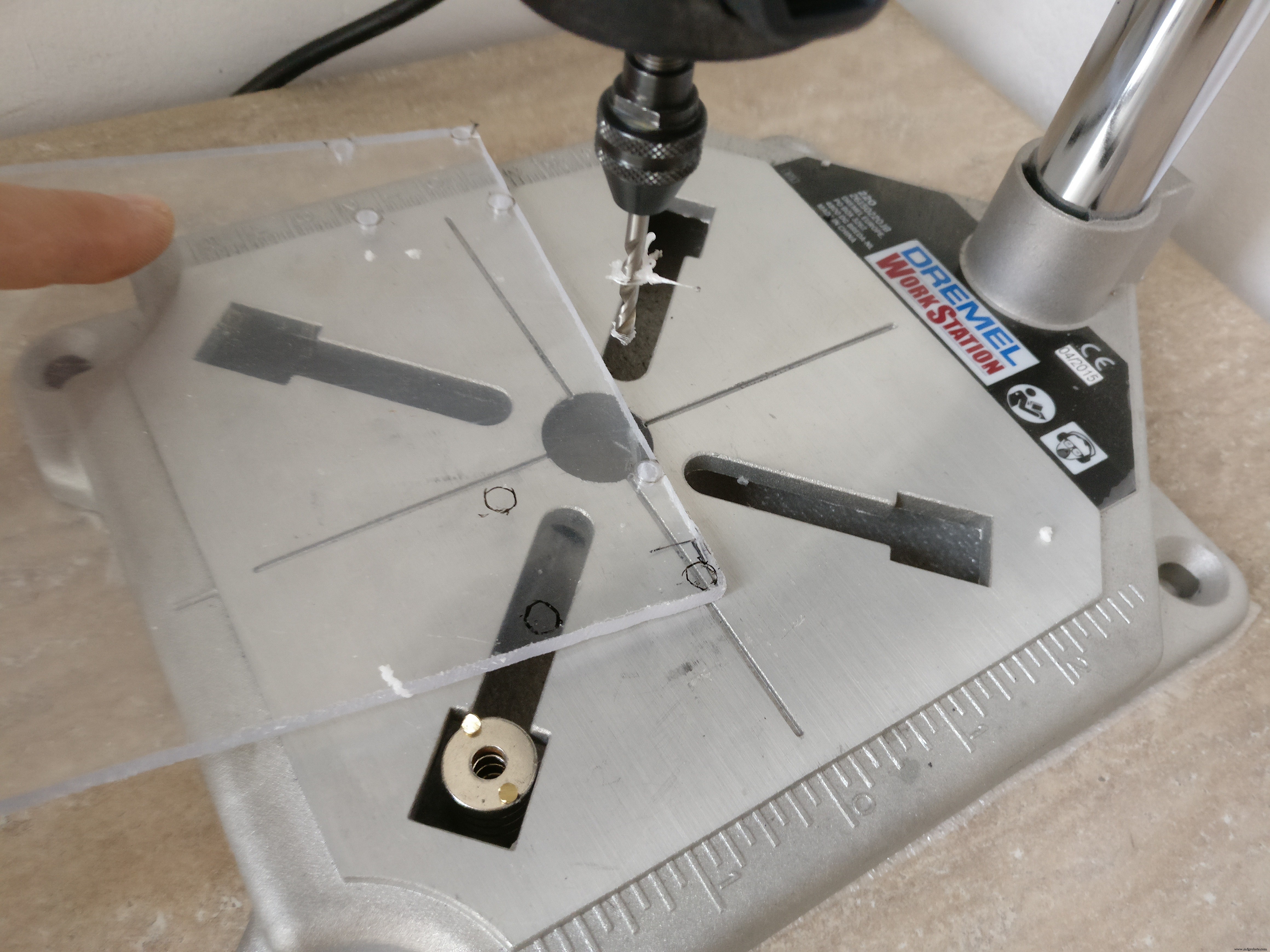
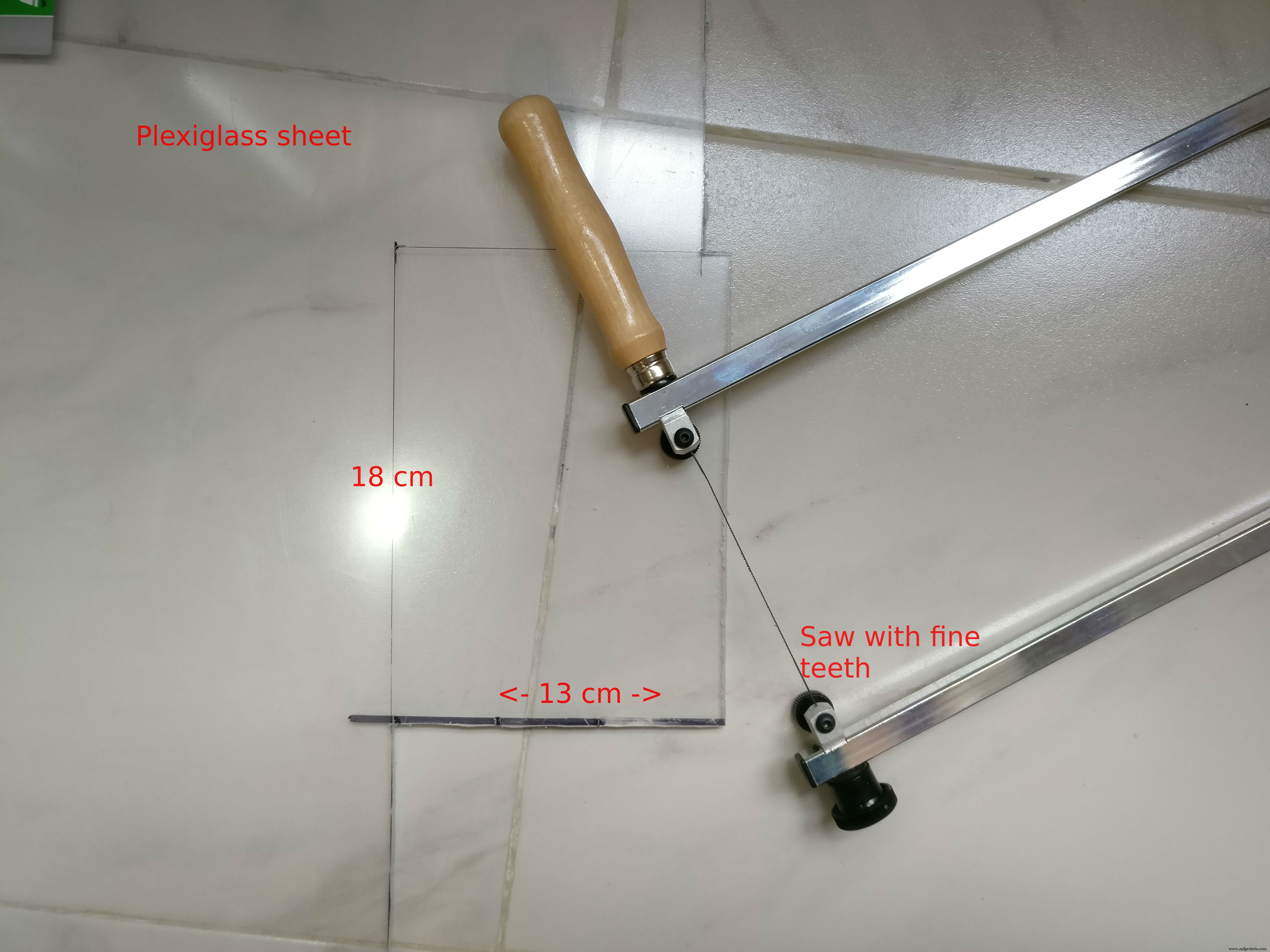

우리는 플렉시 유리 또는 단단한 플라스틱으로 로봇을 만들 것입니다. 저는 둘 다 사용했지만 원하는 것을 선택할 수 있습니다.
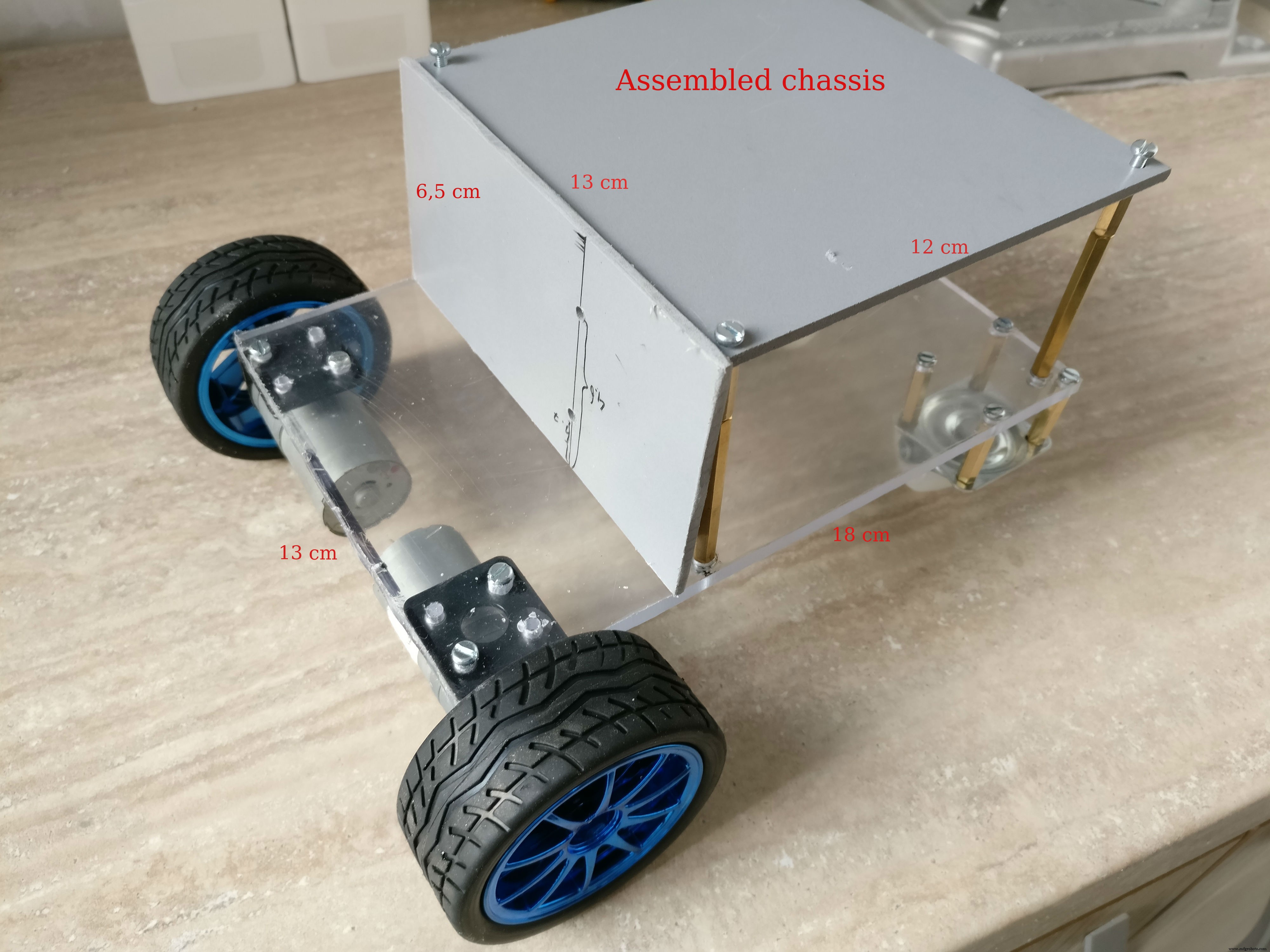
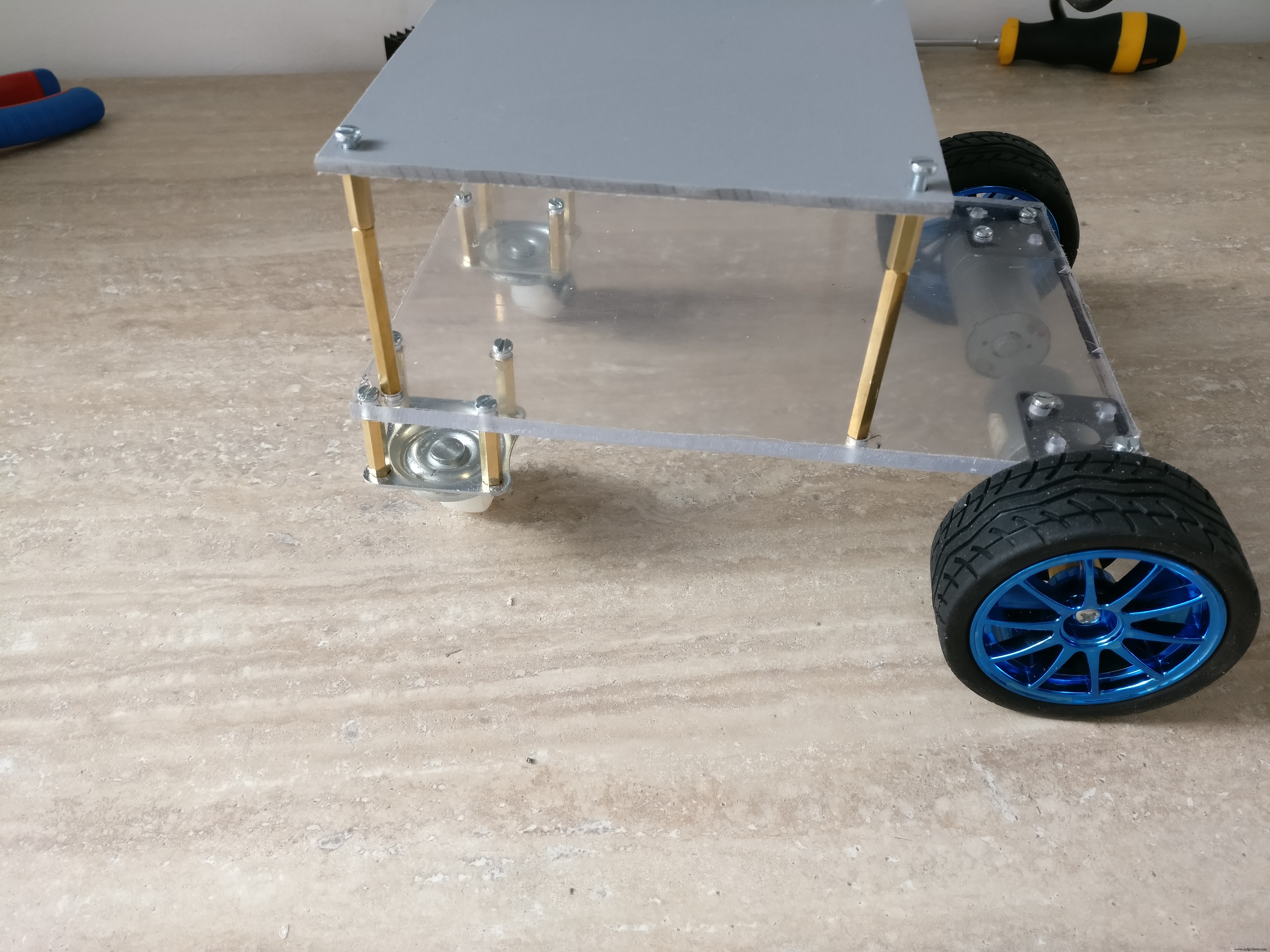
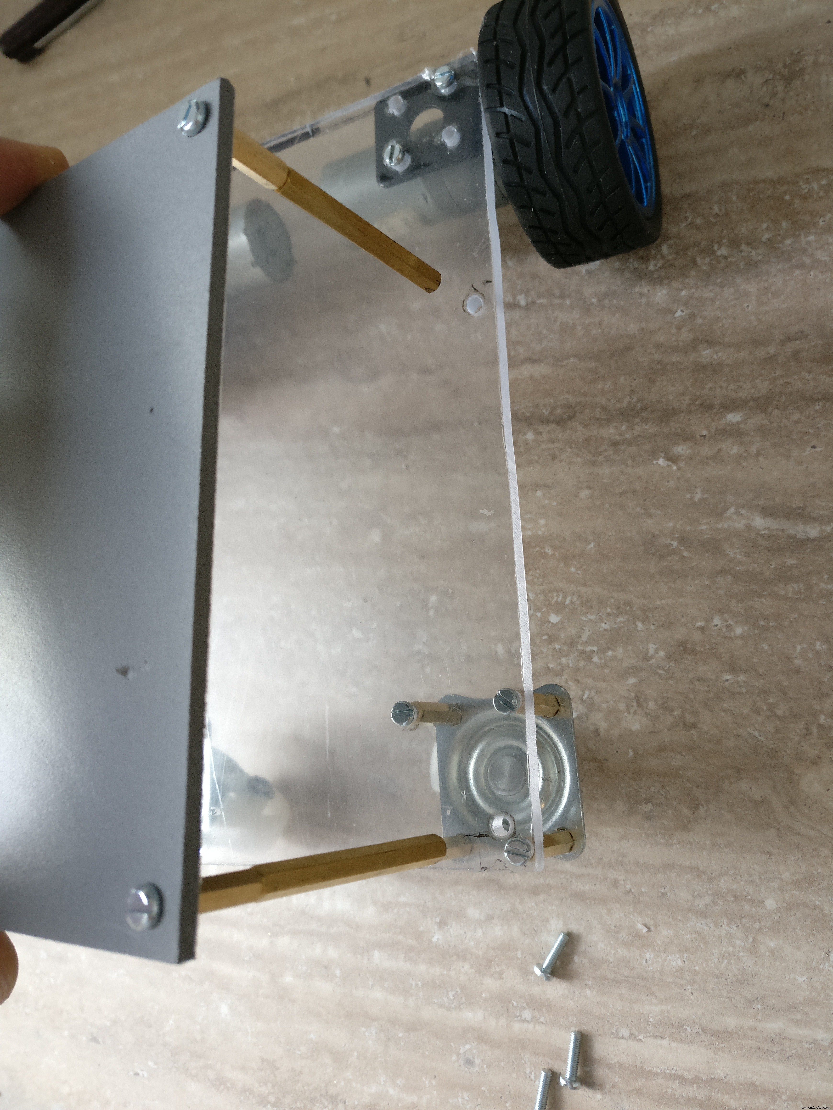
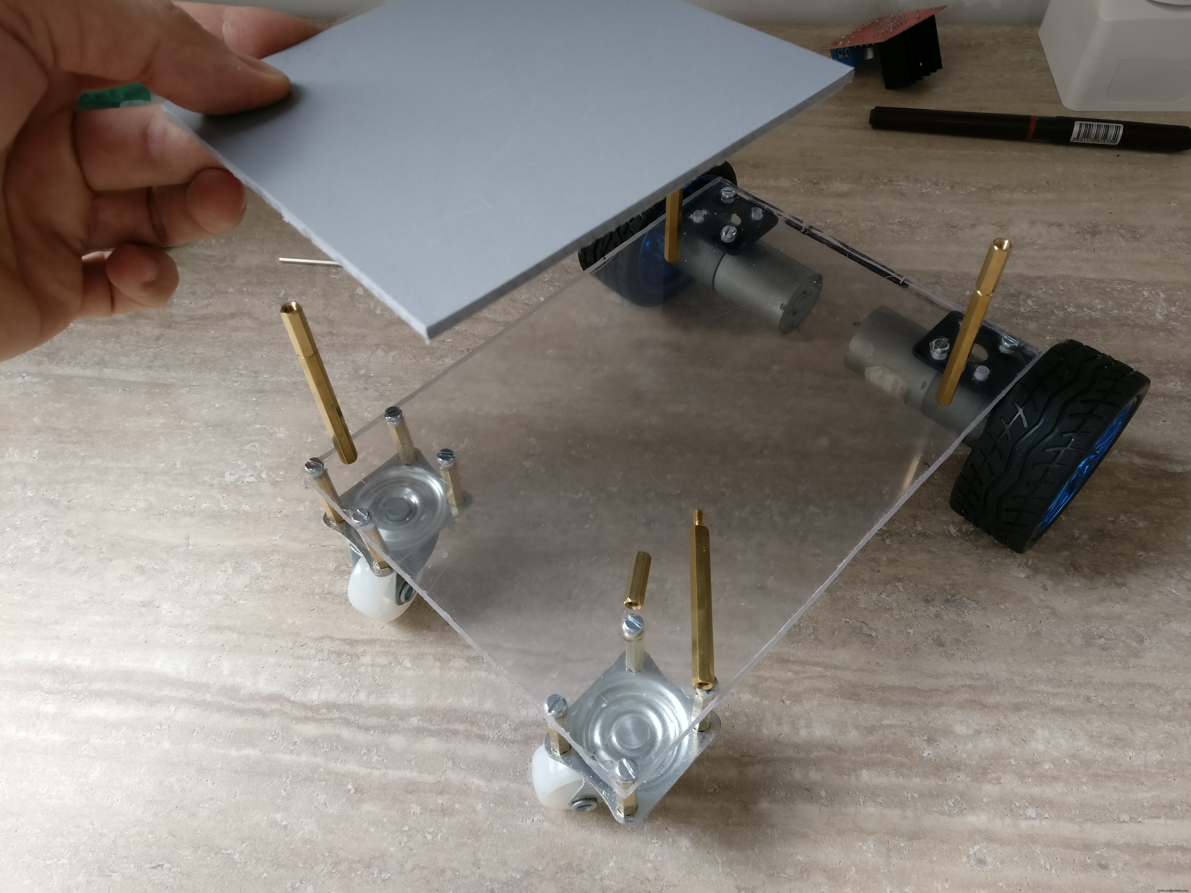
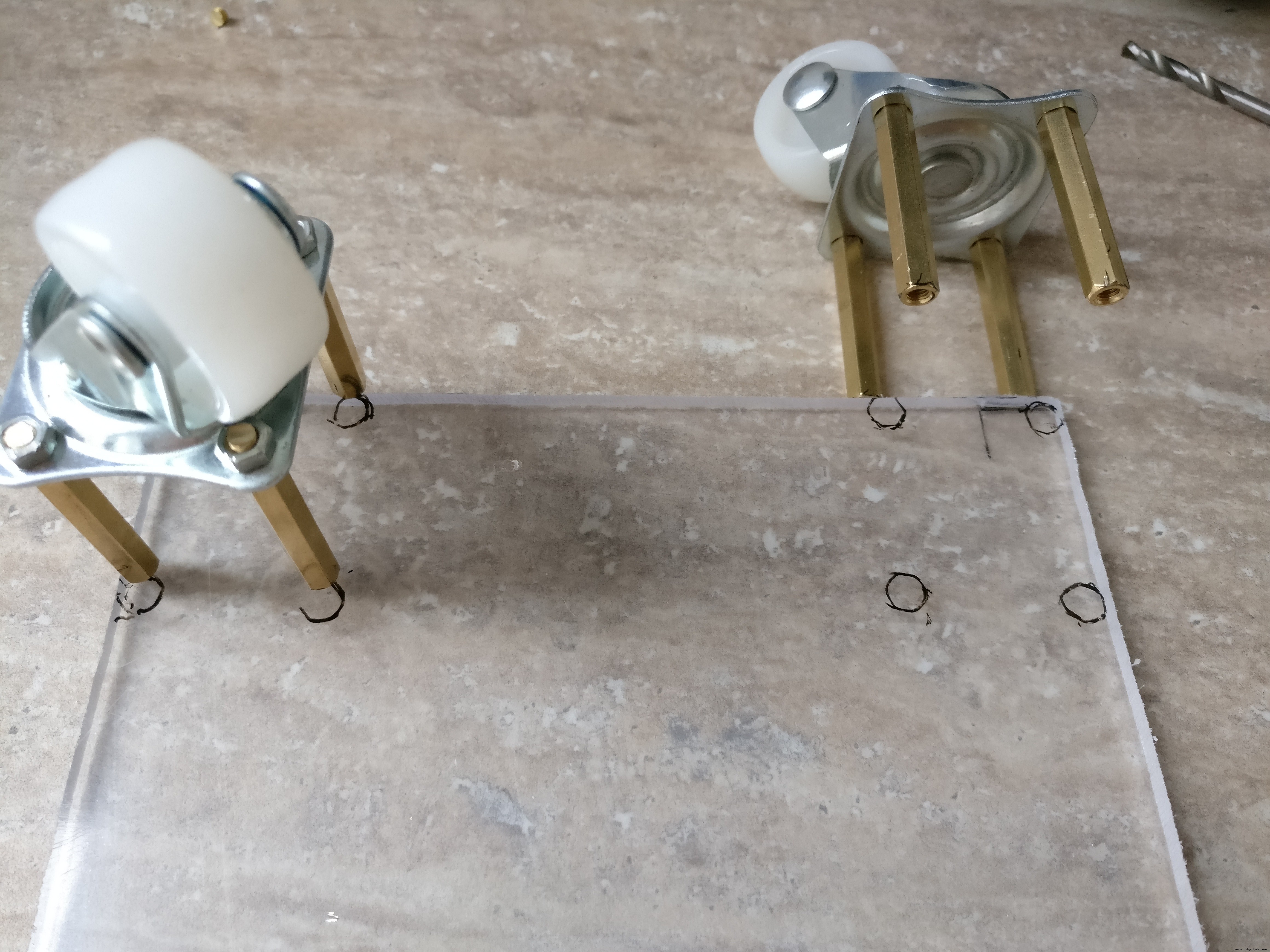
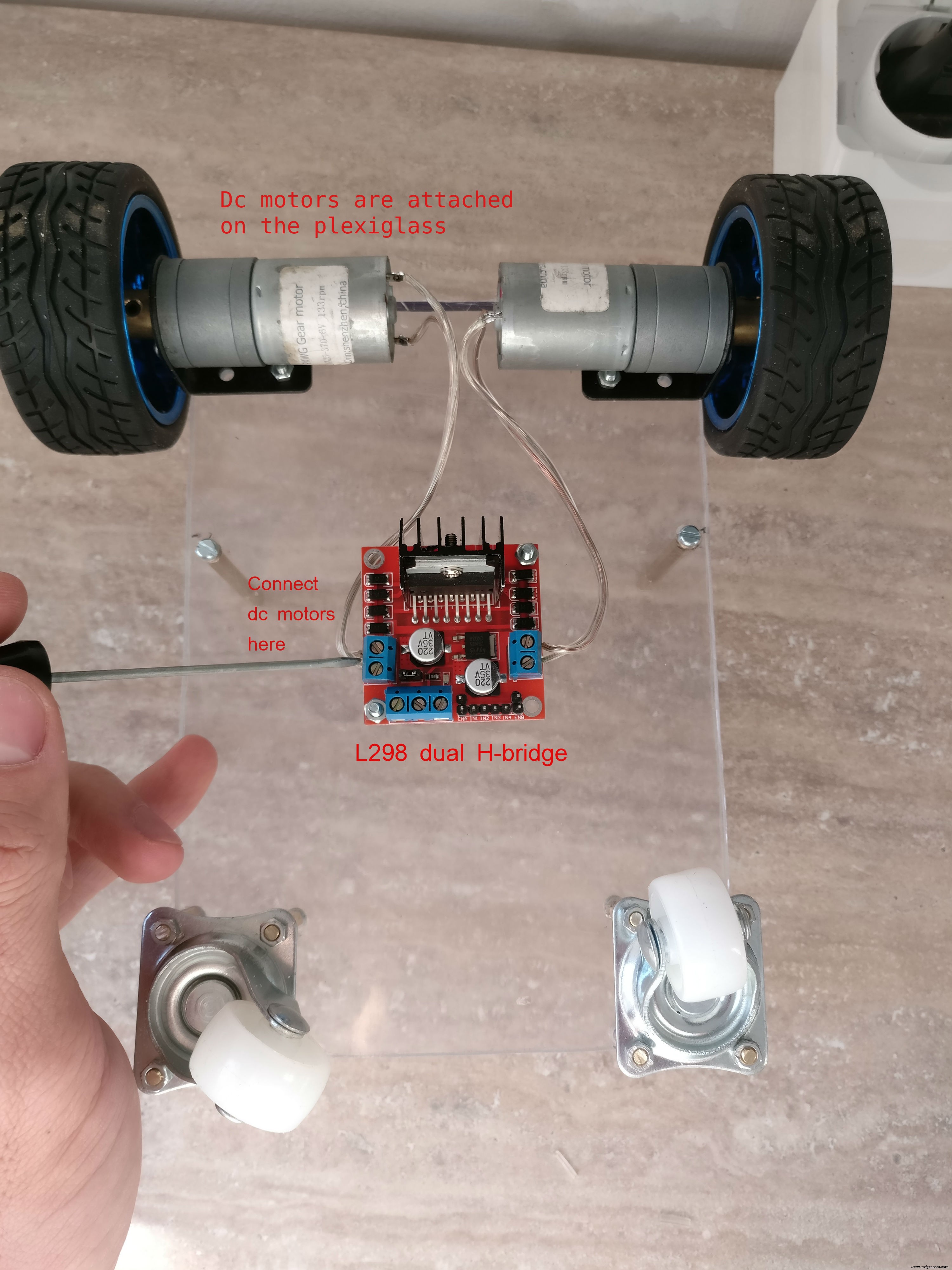
베이스 플레이트 베이스 플레이트에서 18 x 13 cm가 될 것이며 DC 엔진은 금속 브래킷 너트와 볼트로 부착될 것입니다. H-bridge는 바닥을 향한 플레이트의 중앙에 장착됩니다. 뒷바퀴는 2cm 육각형 금속 스페이서를 사용하여 부착됩니다(한쪽은 수컷, 한쪽은 암컷)
H-bridge 근처의 큰 구멍은 상단의 전자 장치를 연결하는 데 필요합니다.
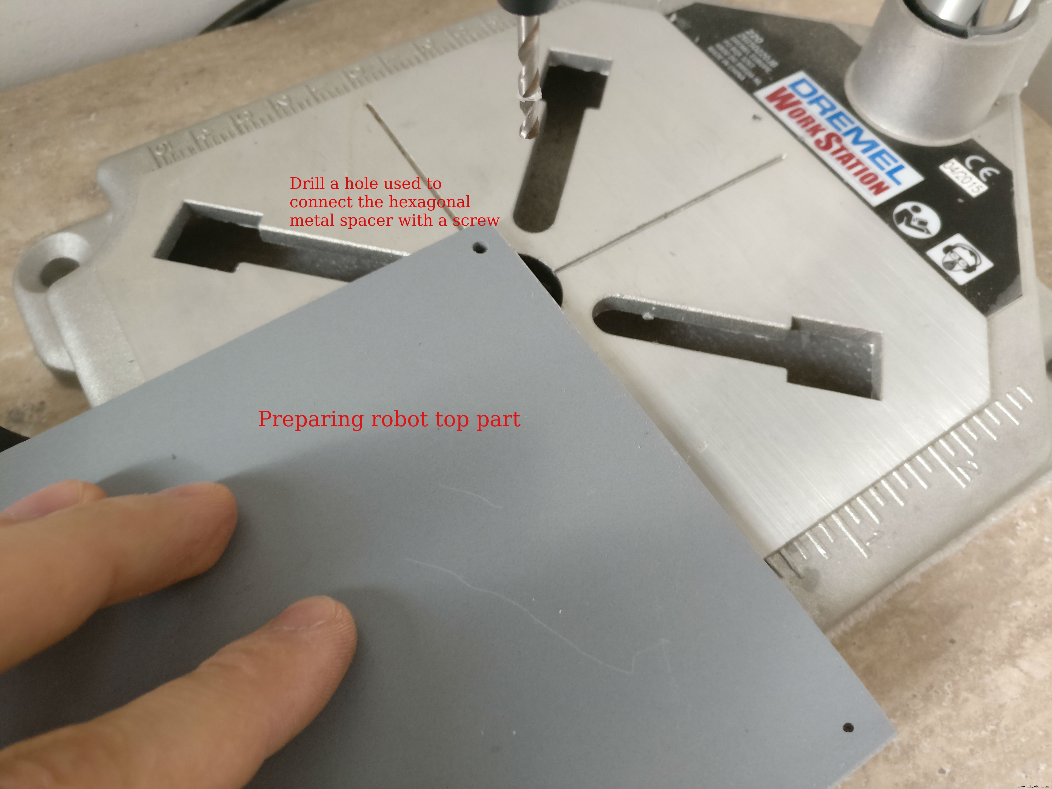
상단 부분 로봇의 하나는 12 x 13 cm이고 다른 하나는 6.5 x 13 cm인 "L" 모양의 두 판으로 구성됩니다. 플라스틱 판은 함께 접착됩니다. 이 플레이트는 전자 장치용 덮개, 헤드라이트를 장착할 장소 및 라즈베리 파이 케이스를 위한 지지대를 제공합니다. 6cm 육각 금속 스페이서를 사용하여 상단 부분을 하단 부분에서 부착합니다)
3단계:전자 제품 제작


핀아웃(arduino):
지도된 손전등:D3
왼쪽 모터:PWM(D5), EN1, EN2(A4, A5)
오른쪽 모터:PWM(D6), EN1, EN2(A3, A2)
적외선 센서:전면(A0), 후면(A1)
라즈베리 파이 통신 핀:Tx:D11, Rx:D10
PCB 조립, 조립
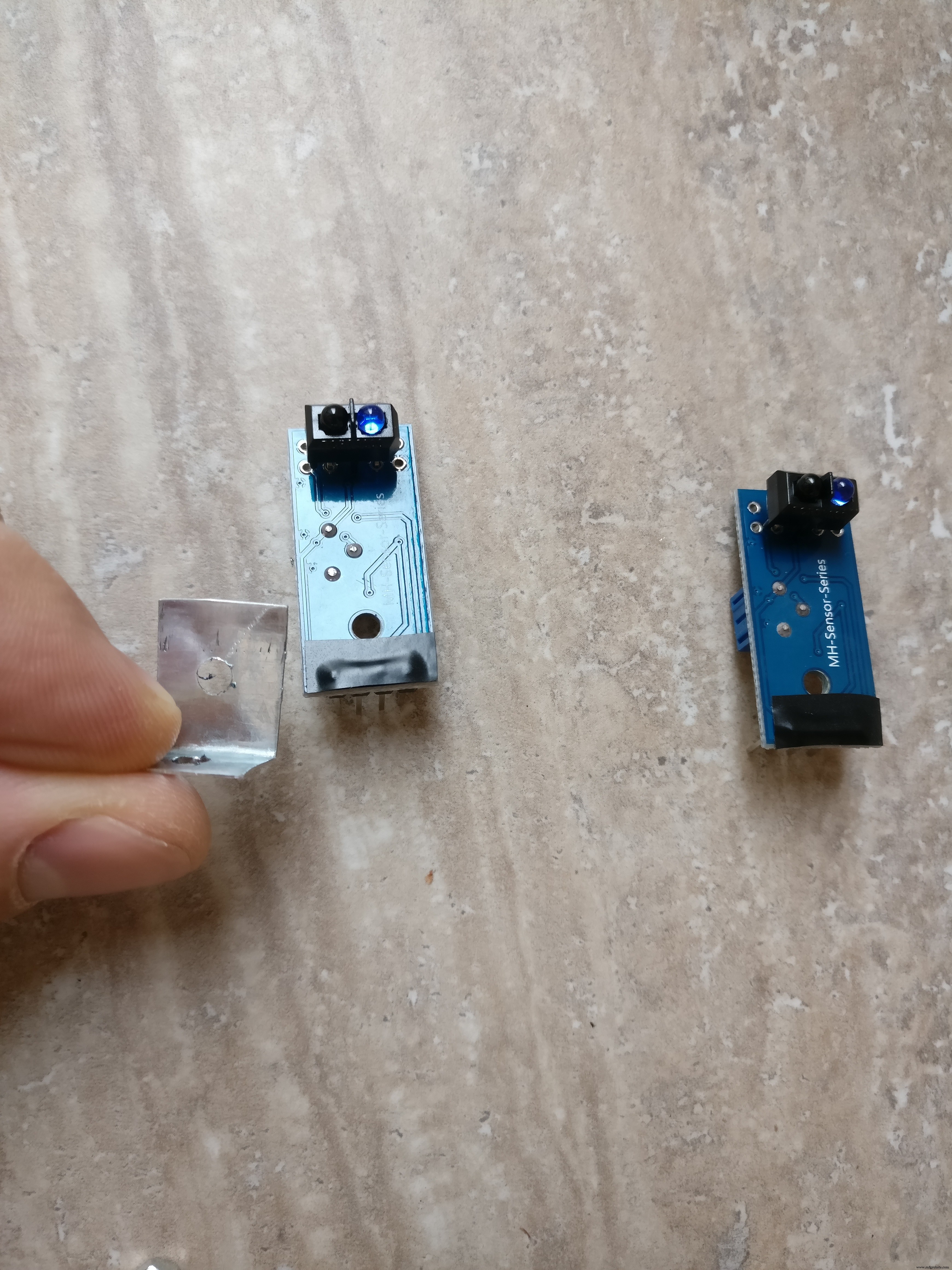
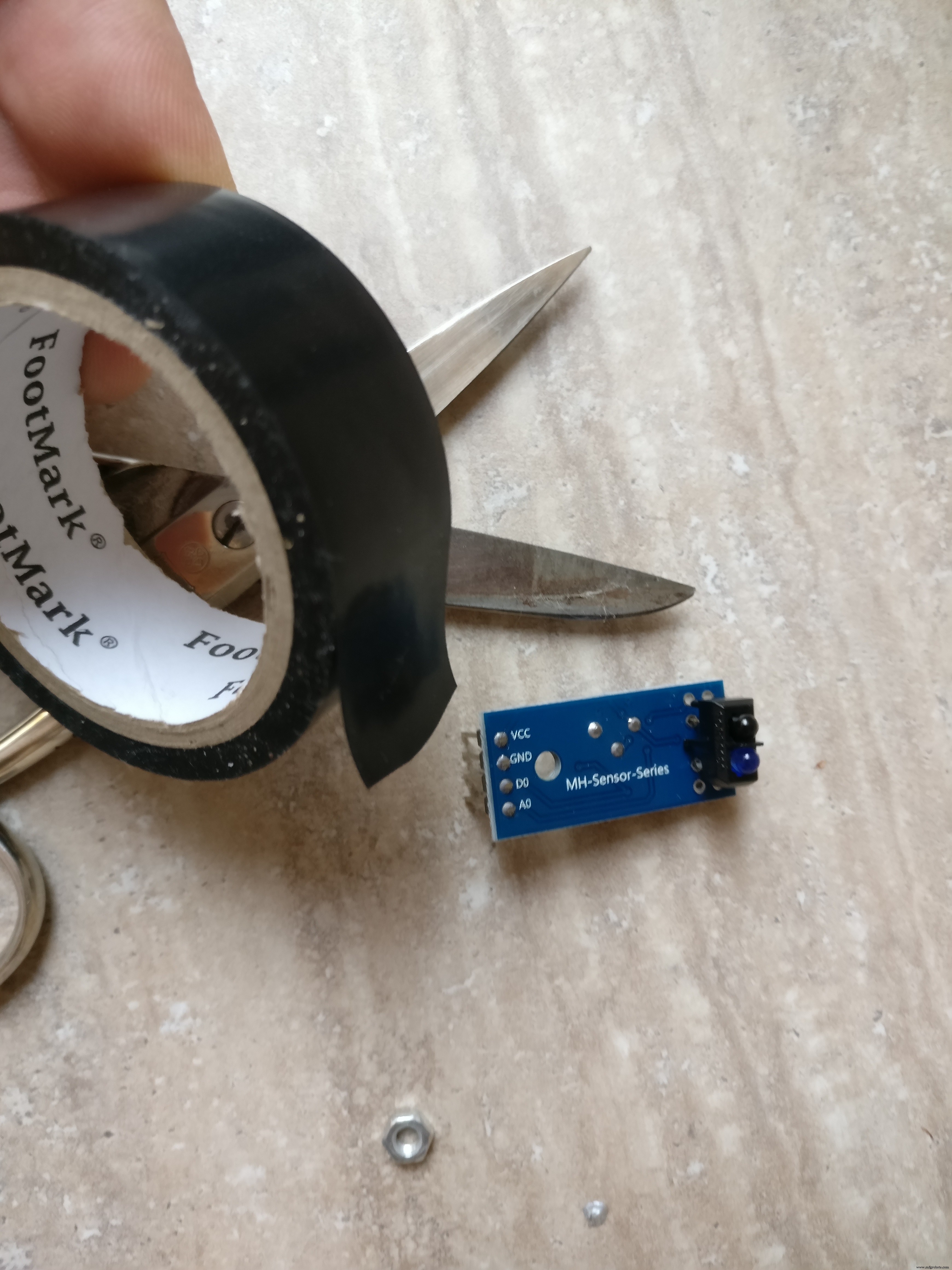
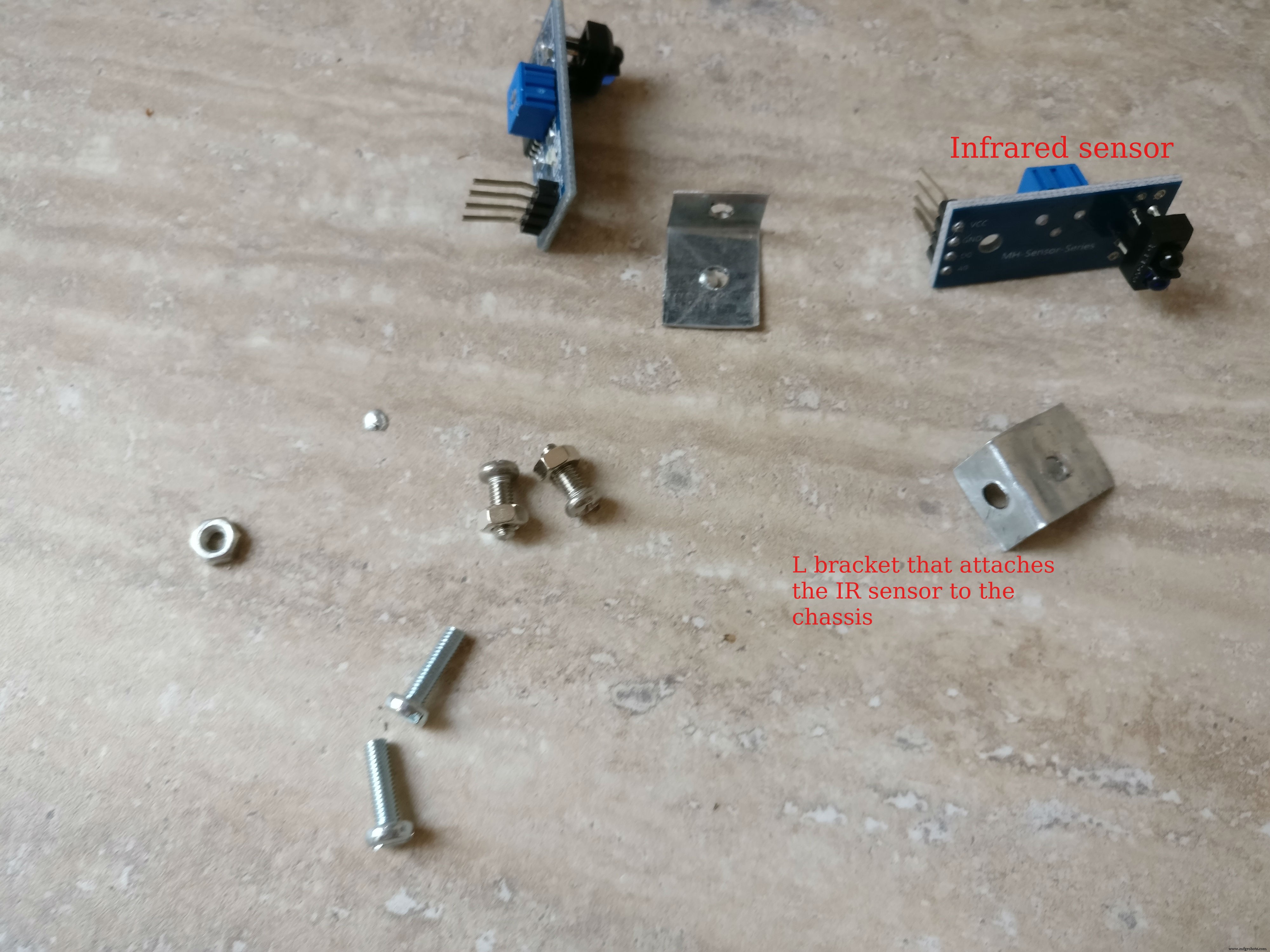
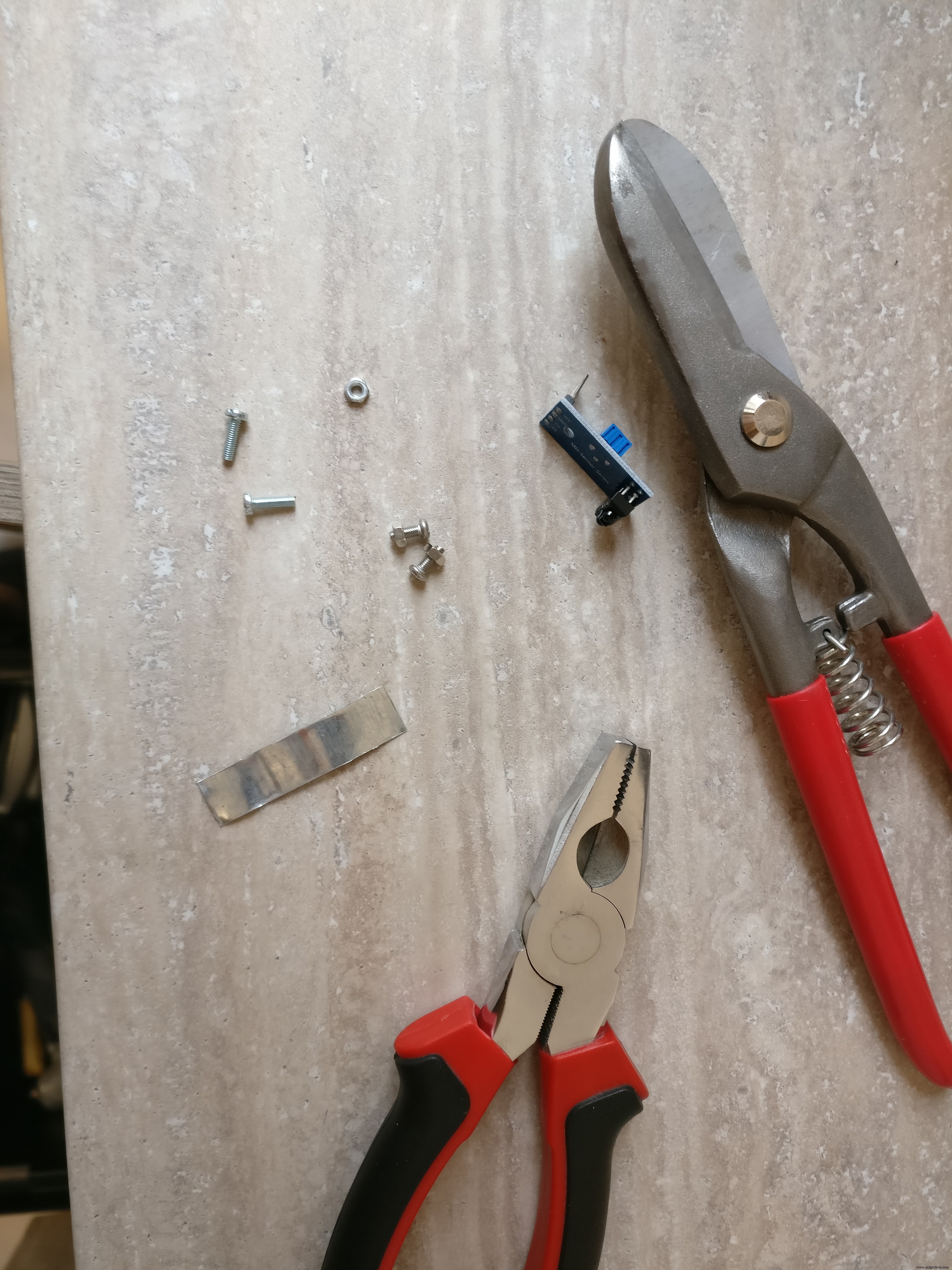
1. 마지막 단계에서 우리는 이미 로봇 바닥면에 H-브리지를 수용했습니다. 또한 두 개의 적외선 센서를 설치해야 합니다. 앞에 하나와 뒤에 하나. 작은 금속판을 사용하여 섀시에 장착할 것입니다. 금속판은 "L"자 모양이며 두 개의 구멍이 있습니다. 너트 볼트를 사용하여 섀시에 설치할 것입니다. 센서는 섀시 중앙에 전면과 후면에 하나씩 있습니다.
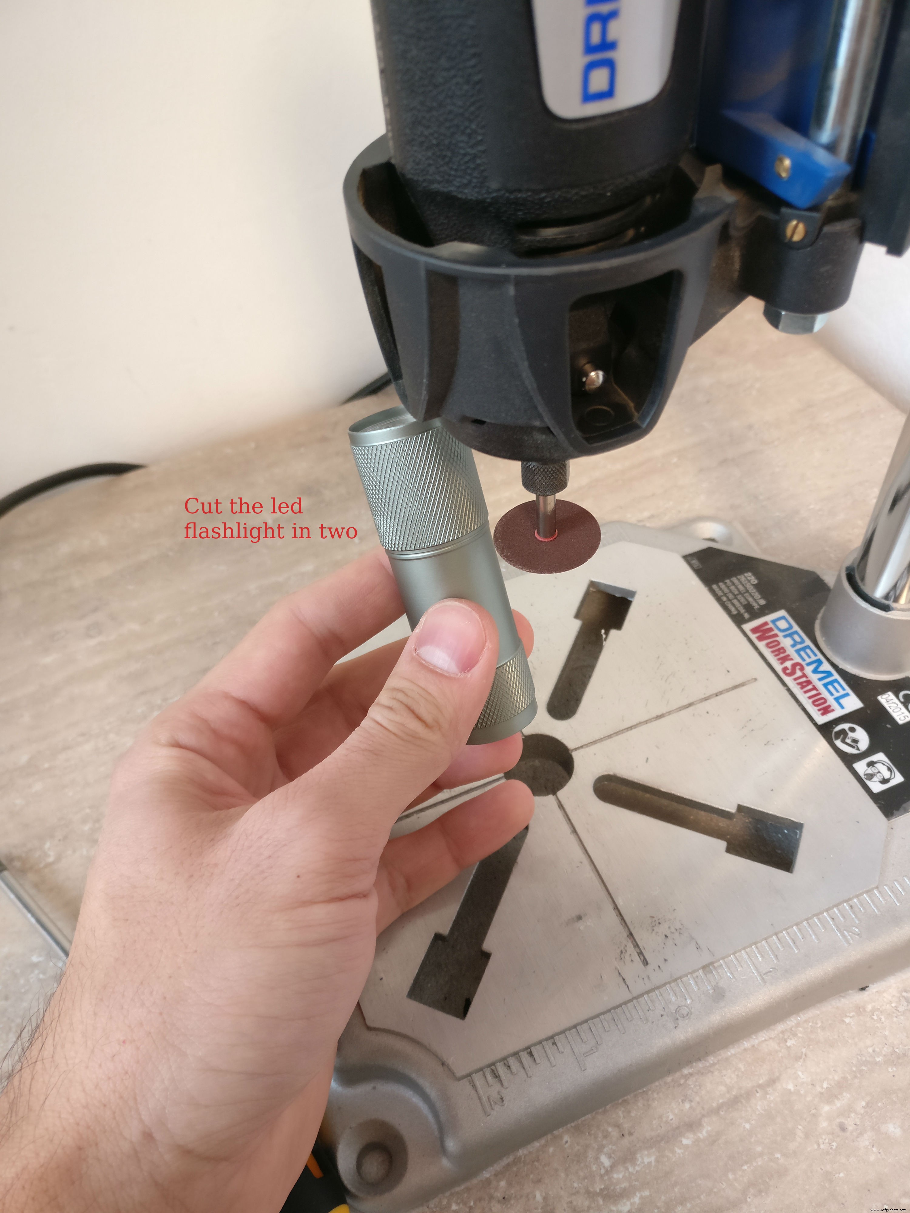
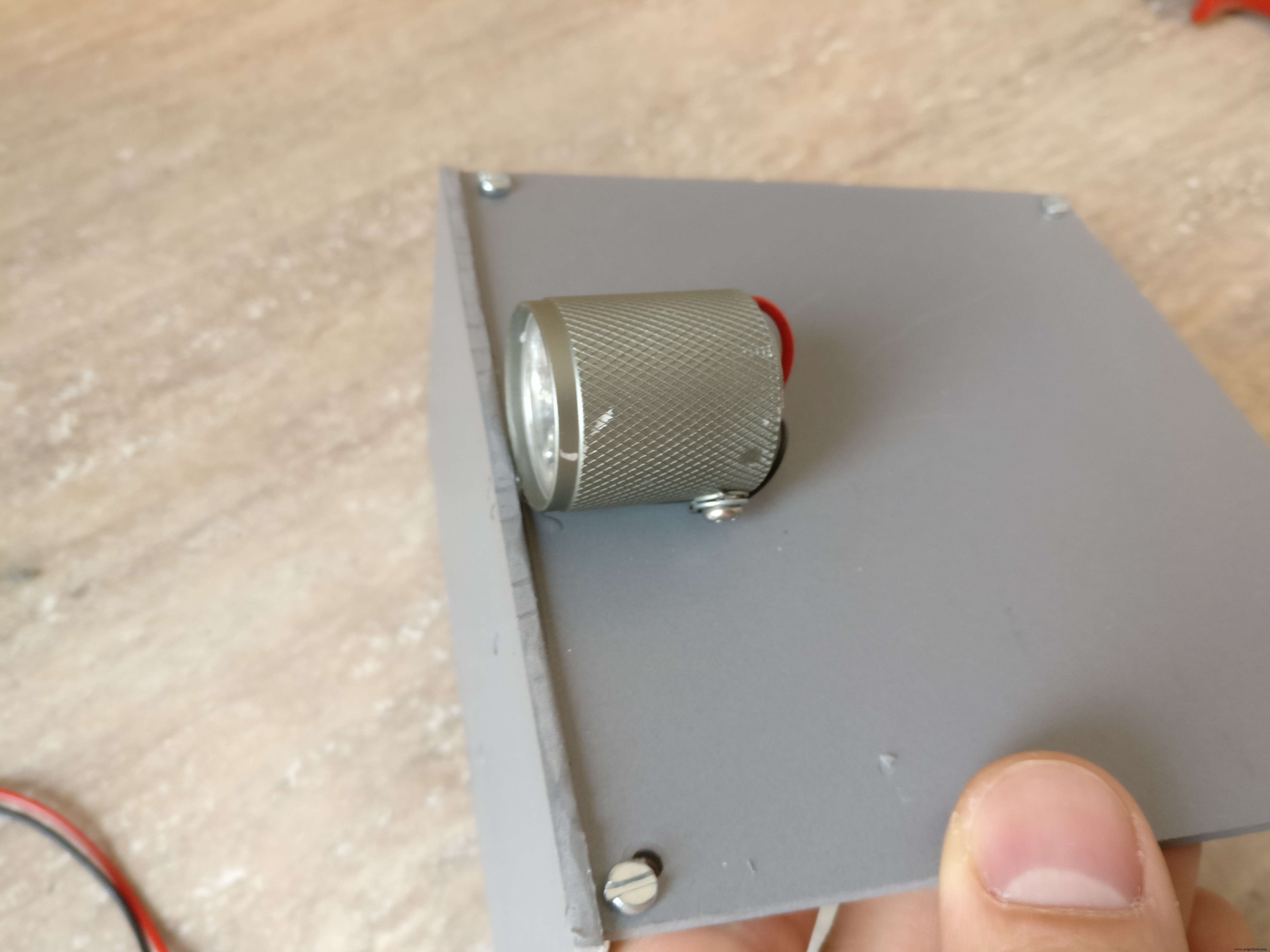
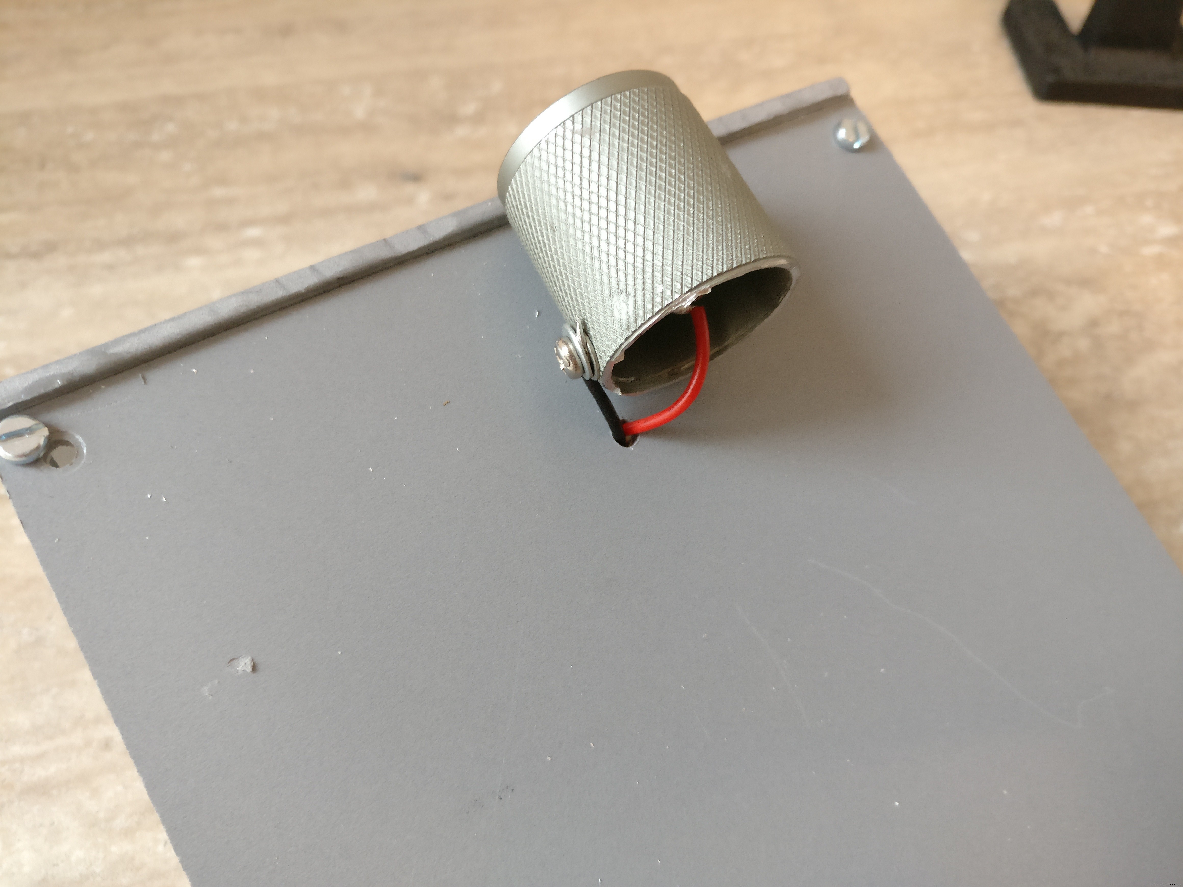
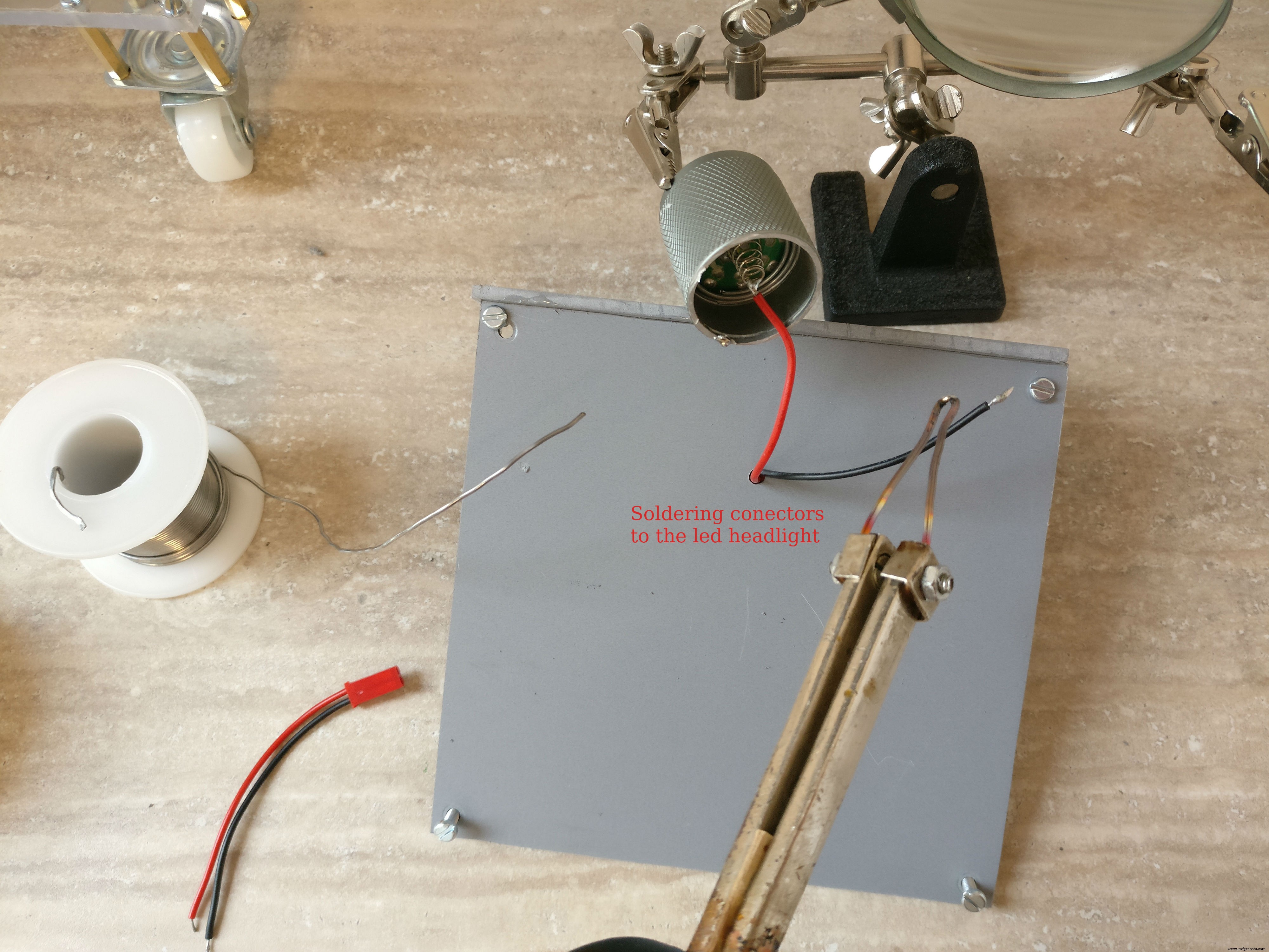
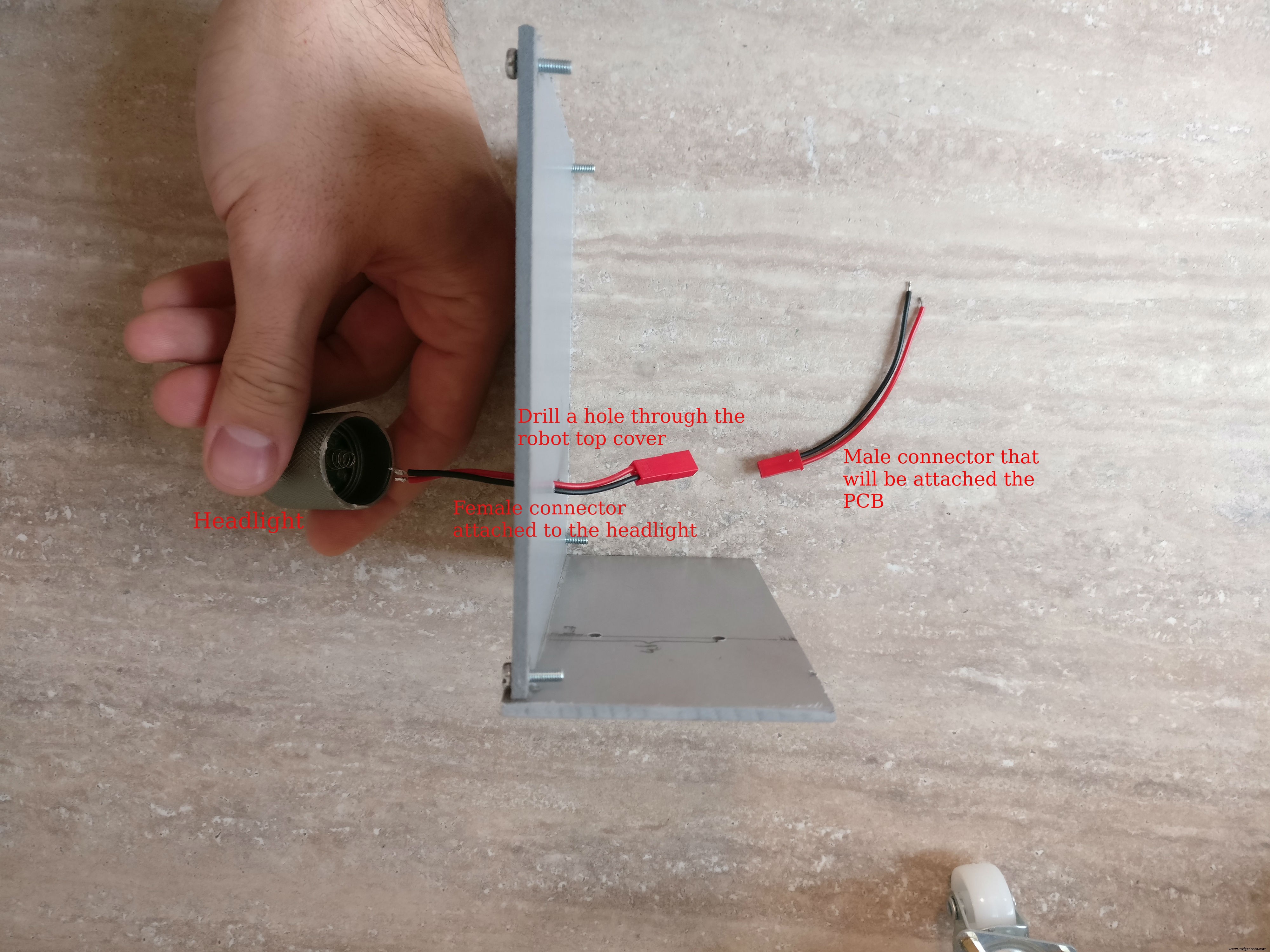
2. 다음 헤드라이트 부품, 나는 이것을 위해 5볼트 led 손전등을 사용했습니다. "머리" 부분만 노출된 헤드라이트를 자르고 두 개의 전선을 납땜하여 전원을 공급했습니다. 그런 다음 로봇 상단 부분의 중앙에 헤드라이트를 붙이고 헤드라이트 근처에 구멍을 뚫었습니다. 구멍에 케이블을 넣고 작은 암 2선식 커넥터를 납땜했습니다.
3. 라즈베리 파이 케이스 조립 라즈베리 파이, 파이 카메라, 4GB 이상의 메모리 카드, 파이 카메라 커넥터가 필요합니다. 최신 Raspian이 설치된 카드를 삽입하고 파이 카메라 커넥터를 가져와 라즈베리 파이에 조심스럽게 삽입한 다음 카메라에 삽입하고 케이스를 닫습니다.
Raspian 운영 체제를 설치하는 방법을 모르는 경우 이 링크를 확인하세요.
카메라 설치 및 활성화 방법에 대한 자세한 내용은 이 공식 문서를 확인하세요.
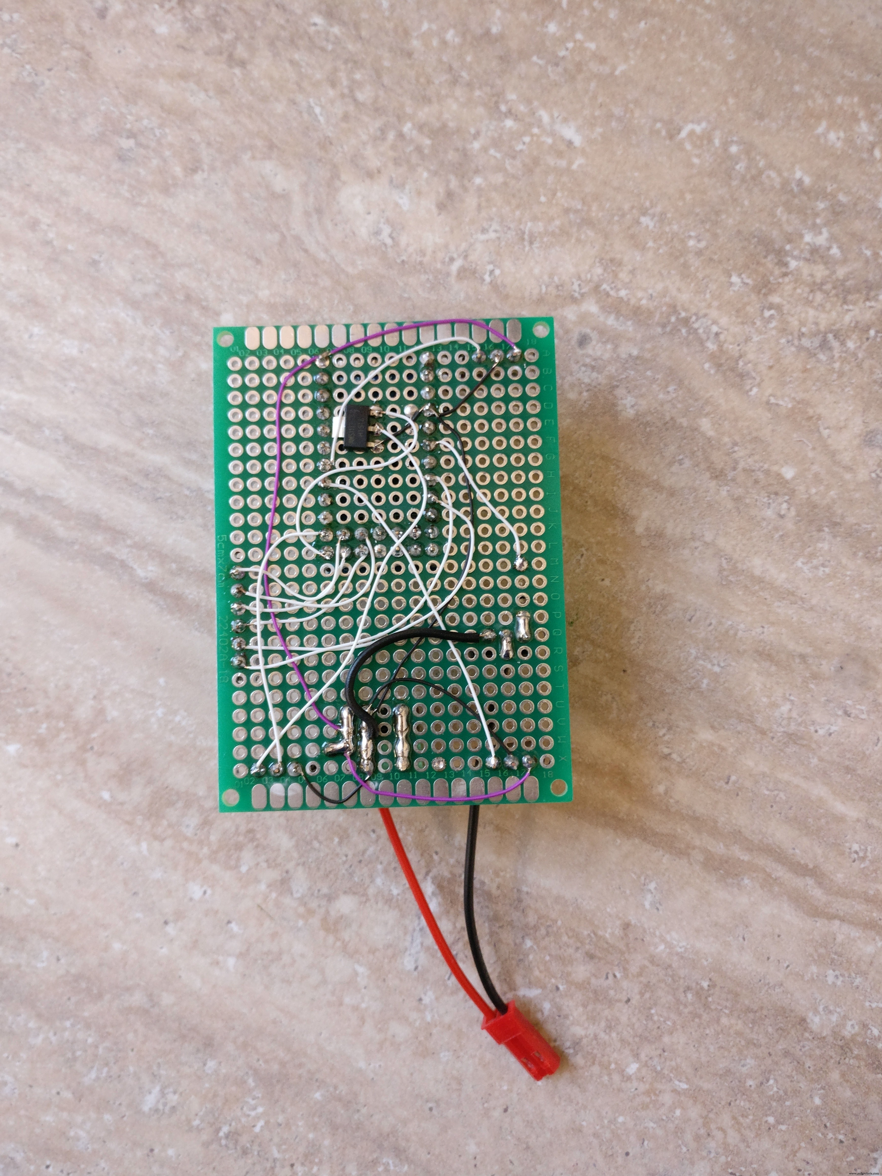
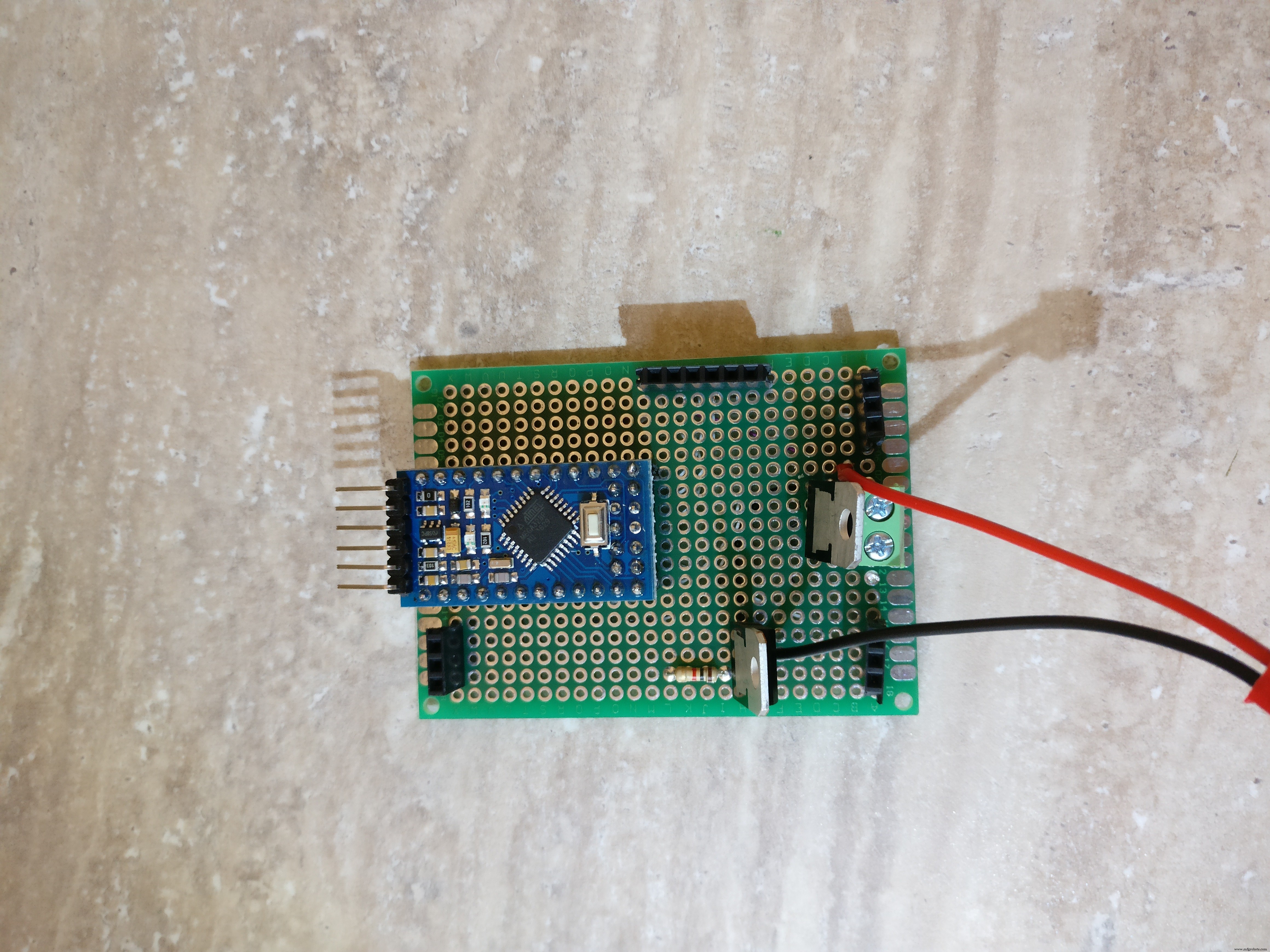
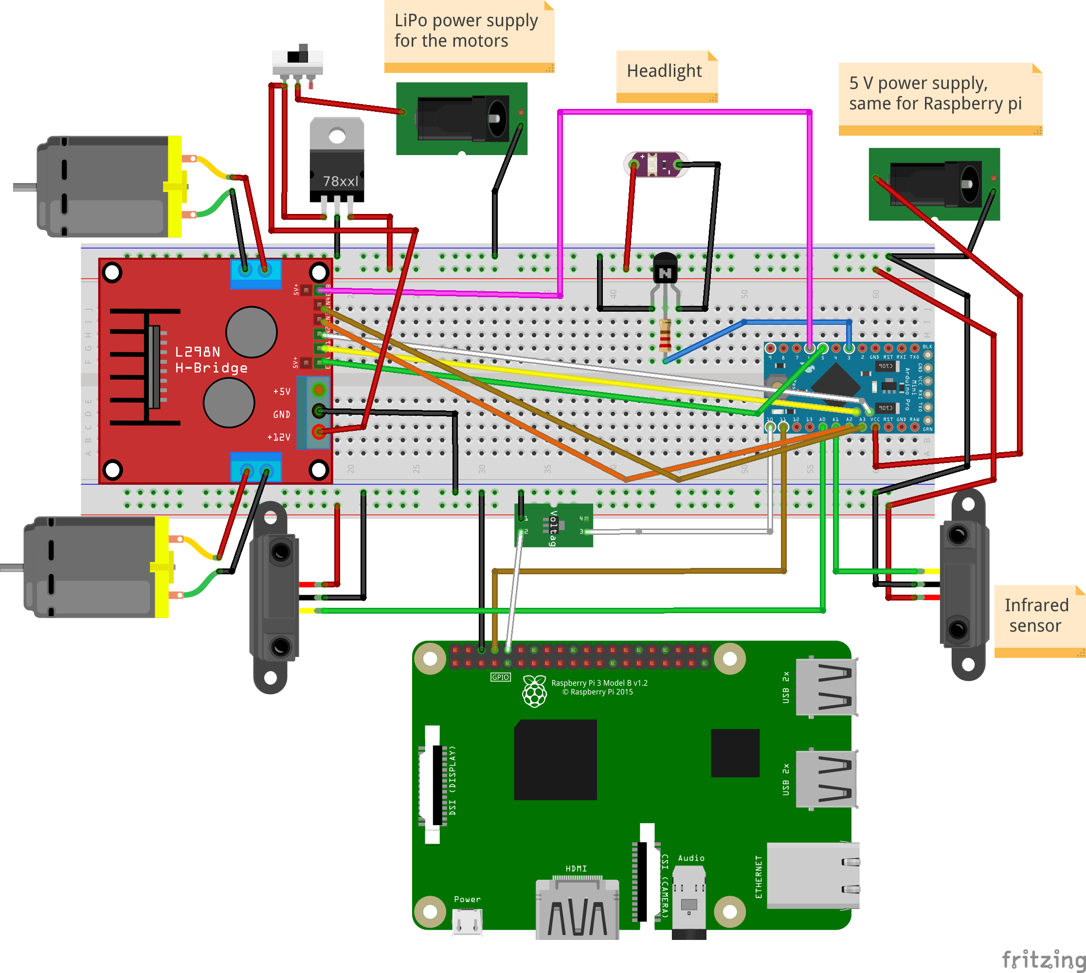
4. 주요 전자 부품으로 PCB를 구축합니다. fzz 형식과 그림으로 fritzing 회로도를 첨부했습니다. 전자제품 조립방법 참고하시면 됩니다.
납땜 단계:
아. 암 PCB 커넥터를 자르십시오. 마이크로 컨트롤러용 2개의 12핀 커넥터와 2개의 5핀 커넥터, IR 센서용 2개의 3핀 커넥터, H 브리지용 6핀 커넥터 및 라즈베리 파이 통신용 핀 커넥터가 있습니다. (그라운드, TX, RX) b. 모든 커넥터를 절단한 후 PCB 뒷면에 납땜해야 합니다.
ㄷ. KF301-2P 커넥터 납땜
d. NPN 트랜지스터와 해당 저항을 베이스에 납땜
. L7805CV 5V 조정기 납땜
f. 3.3볼트 조정기 납땜 arduino에서 raspeberry pi TX 라인으로
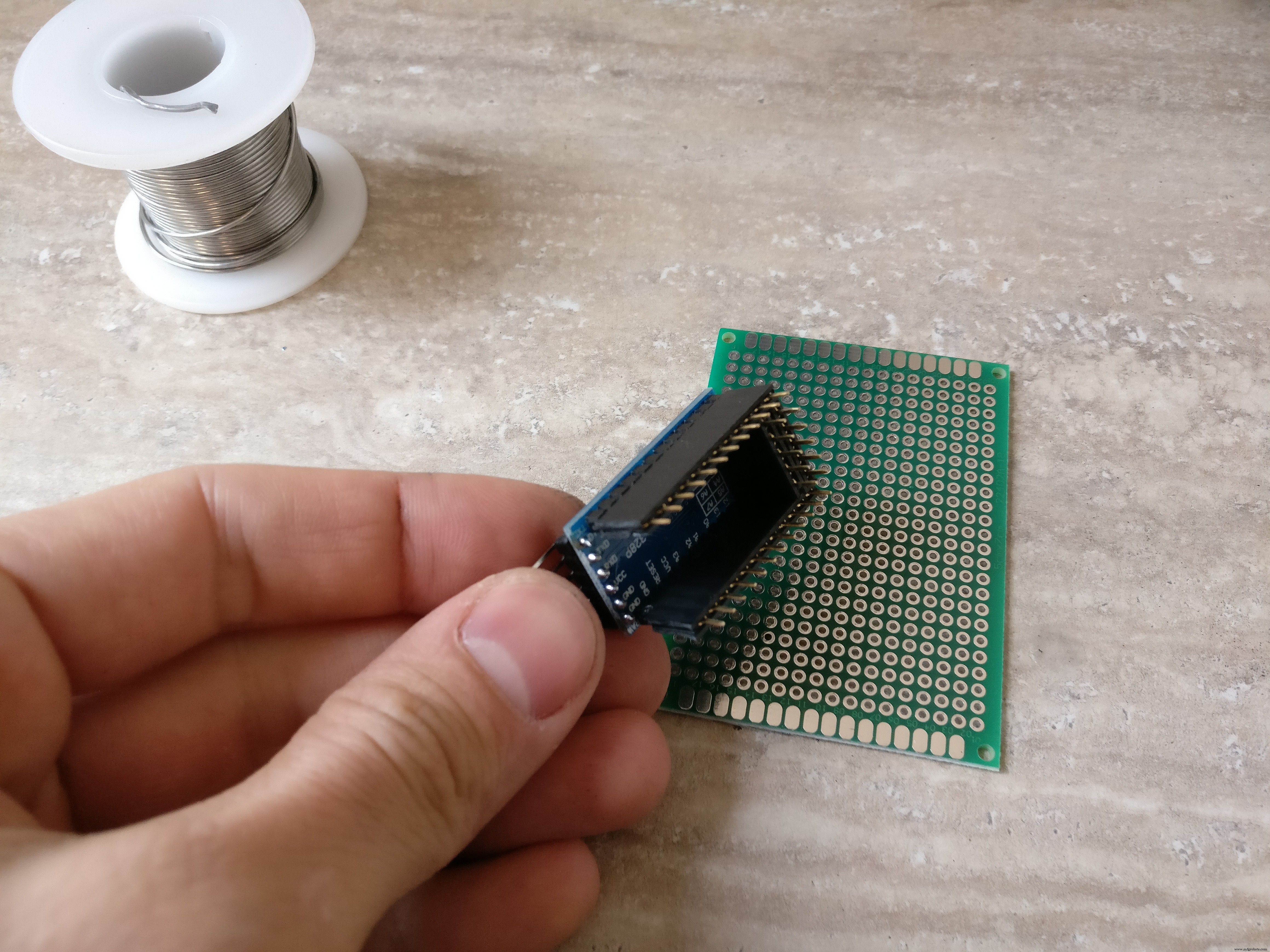
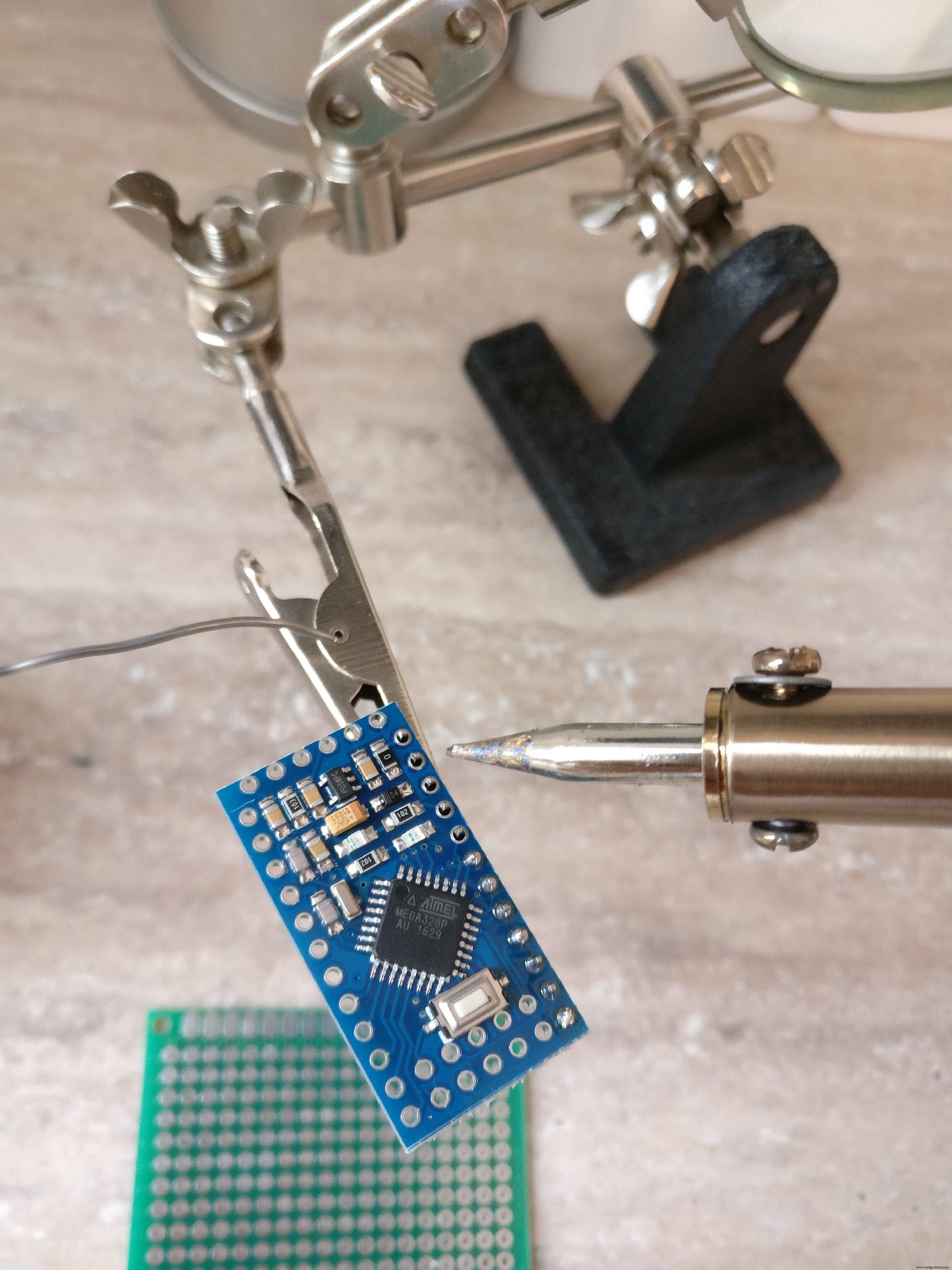
예. arduino pro mini에 수 핀을 납땜합니다.
아. fritzig 회로도에 따라 모든 빨간색(+), 검은색(-) 및 흰색(신호) 가는 와이어를 납땜합니다.
나. 손전등용 브레드보드에 수 커넥터를 납땜합니다.
5. 커넥터
아. 5V USB 배터리 팩에서 라즈베리 파이 및 arduino까지 커넥터를 만들려면 수 USB 커넥터 유형 A, 수 마이크로 USB 커넥터 검정색 및 빨간색 와이어, 열 수축 튜브 및 암 브레드보드 커넥터가 필요합니다. 먼저 암-암 커넥터를 두 개로 자르면 이 부품이 arduino 네거티브 및 포지티브 수 핀에 들어갑니다. A형 USB 커넥터는 마이크로 USB 커넥터를 사용하여 arduino와 라즈베리 파이에 전원을 공급합니다. 납땜 USB 팁은 이미지를 확인하세요.
ㄴ. 커넥터 구축 전자 기판의 LiPo 배터리에 연결하려면 XT-60 암 LiPo 커넥터, 빨간색 및 검은색 전선, 열 수축 튜브 및 10A를 처리할 수 있는 작은 스위치가 필요합니다. 검은색 전선은 XT-60에서 직접 연결됩니다. 전자 보드(KF301-2P 플러그 인 나사 커넥터)에 빨간색 와이어가 작은 스위치를 통해 연결됩니다.
ㄷ. 암-수 브레드보드 커넥터를 사용하여 로봇의 2개의 IR 센서를 PCB의 해당 암 커넥터에 연결합니다.
d. 수 - 암 브레드보드 커넥터를 사용하여 PCB의 6핀 암 커넥터에 H-브리지를 연결합니다.
. 모터 양극 및 음극 단자를 H 브리지에 연결합니다.
f. H-브리지 주 전원 공급 장치를 PCB의 KF301-2P 플러그 인 나사 커넥터에 연결합니다.
6. arduino를 PCB에 배치하기 전에 돋보기와 멀티미터를 사용하여 모든 것을 다시 확인하십시오.
4단계:Arduino 코드
먼저 중요한 질문에 답해야 합니다. Pi를 전자 장치에 직접 연결하지 않고 중간 arduino 레이어가 존재해야 하는 이유는 무엇입니까?
1. 더 모듈식이므로 PI 없이 다른 프로젝트에서 arduino 로봇을 재사용할 수 있습니다.
2. 안전을 위해 Pi(35$)를 교체하는 것보다 3$ arduino pro mini를 교체하는 것이 더 저렴합니다.
3. arduino는 pi와 같이 운영 체제의 방해를 받지 않으므로 모터에 대해 PWM 제어를 구현하고 초당 몇 번씩 전면 및 후면 센서를 폴링하는 것이 더 효율적입니다.
4. Python 스크립트에서 오류가 발생할 수 있는 경우 로봇이 계속 실행되어 배터리를 소모하고 감독하지 않으면 배터리가 손상되거나 화재가 발생할 수 있습니다. arduino 스케치에서는 운영 체제에 의존하지 않기 때문에 안전 장치가 더 안정적입니다.
5. 분리된 시스템을 디버그하기가 더 쉽습니다.
좋아, 왜 이유 부분을 다뤘고 arduino 스케치를 조금 설명하겠습니다. 기본적으로 다음 두 가지 작업을 수행합니다.
1. 수신 모터 및 조명 명령 직렬 라인에서 모터를 구동하거나 조명을 토글
예:
* "남:-25:16; "는 (-25 왼쪽), (16 전력)을 의미하며 왼쪽 모터 17%, 오른쪽 모터 32%, 앞으로 방향 * "M:44:19; "는 (오른쪽으로 44) 및 (19 전력)을 의미합니다. 왼쪽 모터 38%, 오른쪽 모터 5% 및 앞으로 방향
* "L:1; "는 조명을 의미하고 "L:0 " 꺼짐
2. 적외선 센서를 폴링합니다. 로봇의 후면과 전면에서 거리에 대한 데이터를 전송합니다. 직렬 라인을 통해
먼저 다음 라이브러리를 다운로드하여 설치해야 합니다.
기본 코드는 여기 github 저장소에 있습니다. 또는 아래에서 복사하여 붙여넣을 수 있습니다.
FTDI 어댑터를 사용하여 arduino에 코드를 업로드합니다. 이제 로봇이 작동하는 것을 확인하기 위해 명령을 내릴 수 있습니다. 두 번째 직렬 라인을 연결하고 이를 통해 모터나 빛을 보내기만 하면 됩니다. 이를 수행하는 한 가지 방법은 HC-05와 같은 블루투스 모듈을 사용하고 블루투스 애플리케이션을 사용하여 전화에 연결하는 것입니다. 그런 다음 "L:1"과 같은 직렬 명령을 제공합니다.
// TextMotorCommandsInterpretter 소스:"https://github.com/danionescu0/arduino/tree/master/libraries/TextMotorCommandsInterpretter" #include #include const char MOTOR_COMMAND ='엠'; const char LIGHT_COMMAND ='L'; /** * 모터 명령이 ms 단위로 적용되는 시간 * 들어오는 모터 명령은 maxDurationForMottorCommand 동안 지속됩니다. * 다른 모터 명령에 의해 재설정되지 않을 경우 */ const long maxDurationForMottorCommand =300; // 로봇 속도를 제한하기 위해 이 값을 조정합니다. const byte maxPwmValue =230; // 연속적인 거리 전송 사이의 시간(ms) const long transmissionInterval =500; const int maxObstacleDetection =1000; // 아날로그 읽기 최대 감지 값 const int minObstacleDetection =500; // 아날로그 읽기 최소 감지 값 const byte FLASH_PIN =3; 상수 바이트 RIGHT_MOTOR_PWM_PIN =5; 상수 바이트 RIGHT_MOTOR_EN1_PIN =A4; 상수 바이트 RIGHT_MOTOR_EN2_PIN =A5; 상수 바이트 LEFT_MOTOR_PWM_PIN =6; 상수 바이트 LEFT_MOTOR_EN1_PIN =A3; 상수 바이트 LEFT_MOTOR_EN2_PIN =A2; 상수 바이트 FRONT_DISTANCE_SENSOR =A0; 상수 바이트 BACK_DISTANCE_SENSOR =A1; 소프트웨어 직렬 masterComm(11, 10); // RX, TX TextMotorCommandsInterpretter motorCommandsInterpretter(-50, 50, -50, 50); 문자열 현재 명령; 긴 lastCheckedTime; 긴 lastTransmitTime; 부울 inMotion =false; 무효 설정() { Serial.begin(9600); masterComm.begin(9600); masterComm.setTimeout(10); 핀모드(FLASH_PIN, 출력); 핀모드(LEFT_MOTOR_PWM_PIN, 출력); 핀모드(LEFT_MOTOR_EN1_PIN, 출력); 핀모드(LEFT_MOTOR_EN2_PIN, 출력); 핀모드(RIGHT_MOTOR_PWM_PIN, 출력); 핀모드(RIGHT_MOTOR_EN1_PIN, 출력); 핀모드(RIGHT_MOTOR_EN2_PIN, 출력); lastCheckedTime =밀리(); lastTransmitTime =밀리(); } 무효 루프() { if (masterComm.available()> 0) { currentCommand =masterComm.readString(); 프로세스 명령(); } if (inMotion &&millis() - lastCheckedTime> maxDurationForMottorCommand) { stopMotors(); } if (millis() - lastTransmitTime> transmissioningInterval) { lastTransmitTime =millis(); masterComm.print(getObstacleData()); Serial.print(analogRead(BACK_DISTANCE_SENSOR));Serial.print("---"); Serial.println(getObstacleData()); } /* 디버그용 motorCommandsInterpretter.analizeText("M:-14:40;"); Serial.write("Left==");Serial.println(motorCommandsInterpretter.getPercentLeft()); Serial.write("Right==");Serial.println(motorCommandsInterpretter.getPercentRight()); 지연(10000);*/ } 문자열 getObstacleData() { int frontDistance =analogRead(FRONT_DISTANCE_SENSOR); int backDistace =analogRead(BACK_DISTANCE_SENSOR); frontDistance =map(frontDistance, maxObstacleDetection, minObstacleDetection, 0, 10); backDistace =map(backDistace, maxObstacleDetection, minObstacleDetection, 0, 10); return String("F=" + String(frontDistance) + ":B=" + String(backDistace) + ";"); } 무효 processCommand() { 스위치(currentCommand.charAt(0)) { 경우(MOTOR_COMMAND):steerCar(); 부서지다; 경우(LIGHT_COMMAND):toggleLight(currentCommand.charAt(2)); 부서지다; } } 무효 steerCar() { motorCommandsInterpretter.analizeText(currentCommand); float 퍼센트LeftMotor =motorCommandsInterpretter.getPercentLeft(); float percentRightMotor =motorCommandsInterpretter.getPercentRight(); Serial.write("Left=");Serial.println(percentLeftMotor); Serial.write("오른쪽=");Serial.println(percentRightMotor); setMotorsDirection(motorCommandsInterpretter.getDirection()); analogWrite(LEFT_MOTOR_PWM_PIN, 퍼센트LeftMotor * maxPwmValue); analogWrite(RIGHT_MOTOR_PWM_PIN, 퍼센트RightMotor * maxPwmValue); 인모션 =참; lastCheckedTime =밀리(); } 무효 setMotorsDirection(부울 포워드) { if (forward) { digitalWrite(LEFT_MOTOR_EN1_PIN, HIGH); 디지털 쓰기(LEFT_MOTOR_EN2_PIN, LOW); 디지털 쓰기(RIGHT_MOTOR_EN1_PIN, HIGH); 디지털 쓰기(RIGHT_MOTOR_EN2_PIN, LOW); } else { digitalWrite(LEFT_MOTOR_EN1_PIN, LOW); 디지털 쓰기(LEFT_MOTOR_EN2_PIN, HIGH); 디지털 쓰기(RIGHT_MOTOR_EN1_PIN, LOW); 디지털 쓰기(RIGHT_MOTOR_EN2_PIN, HIGH); } } 무효 stopMotors() { Serial.println("모터 정지"); analogWrite(LEFT_MOTOR_PWM_PIN, 0); analogWrite(RIGHT_MOTOR_PWM_PIN, 0); 인모션 =거짓; } 무효 toggleLight(char 명령) { Serial.println("토글 라이트"); if (명령 =='1') { digitalWrite(FLASH_PIN, HIGH); } else { digitalWrite(FLASH_PIN, LOW); } }
5단계:Raspberry Pi 프로젝트 및 종속성 설치 및 구성
작동 방식:
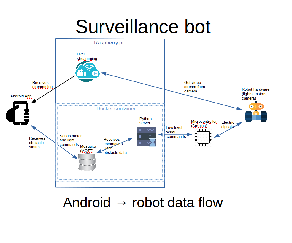
위에 첨부된 이미지에서 제가 설명하려고 하는 다이어그램을 볼 수 있습니다.
아. Android 앱은 webview 내에서 uv4l 스트리밍을 보여줍니다. uv4l 프로세스는 raspberry pi에서 실행되고 카메라에서 비디오 입력을 캡처하고 스트리밍합니다. 많은 기능을 갖춘 멋진 도구입니다.
ㄴ. Android 앱 조명 및 엔진 내에서 컨트롤을 사용하면 MQTT 서버에 명령이 실행됩니다.
ㄷ. raspberry pi의 docker 컨테이너 내부에 있는 python 서버는 MQTT 명령을 수신하고 직렬 인터페이스를 사용하여 arduino에 전달합니다. arduino 보드는 모터와 조명을 제어합니다.
d. arduino는 로봇의 앞뒤 거리를 감지하고 직렬 인터페이스를 통해 데이터를 Python 서버로 보내고, Python은 이를 MQTT로 전달하고 Android 인터페이스에서 선택하여 사용자에게 표시합니다.
첫 번째 라즈베리 파이에 완전히 설치되고 구성된 Raspbian이 필요하고 카메라가 심리적으로 연결되고 구성되어야 합니다. 또한 모든 구성은 ssh를 사용하여 수행되므로 구성하는 것이 좋습니다.
여기에서 모든 기본 사항을 다룰 수는 없지만 필요한 경우 다음 링크를 시도해 보세요.
Raspbian 운영 체제를 설치하는 방법을 모르는 경우 이 링크를 확인하십시오. 카메라 설치 및 활성화 방법에 대한 자세한 내용은 이 공식 문서를 확인하세요.
Raspbian에서 ssh를 설정하는 방법은 여기를 확인하세요.
Wi-Fi 외부에서 Android 앱을 사용하여 로봇을 제어하려면 Wi-Fi 라우터에서 포트 전달을 고려해야 합니다. 그렇지 않으면 Wi-Fi 내부에서 로컬 IP 주소를 사용하도록 제한됩니다.
라즈베리 파이에서 로컬 IP 주소를 찾으려면 "ifconfig"를 사용하세요.
ifconfig ....... eth0 링크 encap:Ethernet HWaddr b8:27:eb:16:e7:ff inet6 addr:fe80::ff00:f22f:9258:b92b/64 범위:Link UP BROADCAST MULTICAST MTU:1500 메트릭:1 RX 패킷:0 오류:0 삭제:0 오버런:0 프레임:0 TX 패킷:0 오류:0 삭제:0 오버런:0 캐리어:0 충돌:0 txqueuelen:1000 RX 바이트 :0 (0.0 B) TX 바이트:0 (0.0 B) ....... wlan0 링크 encap:Ethernet HWaddr 00:c1:41:00:10:f6 inet addr:192.168.0.102 Bcast:192.168.0.255 Mask:255.255.255.0 inet6 addr:fe80::e1f4:5112:9cb2:3839/64 범위:Link UP BROADCAST RUNNING MULTICAST MTU:1500 Metric:1 RX 패킷:1678396 오류:0 삭제된 TX 프레임:0 오버런 패킷:381859 오류:0 삭제:0 오버런:0 캐리어:0 충돌:0 txqueuelen:1000 RX 바이트:259428527 (247.4 MiB) TX 바이트:187573084 (178.8 MiB) ..... 우리의 경우 "192.168.0.102"인 wlan0 inet addr에 관심이 있습니다.
전달할 포트(기본값)는 uv4l의 경우 9090이고 모기의 경우 1883입니다. 인터넷 공급자 방화벽이나 다른 포트에서 금지되지 않은 경우 이 포트를 동일한 출력 포트로 전달할 수 있습니다.
포트 포워딩은 라우터마다 다르게 수행되는 작업입니다. 여기에 몇 가지 자습서가 있습니다. 또한 Google에서 "포트 포워딩 your_router_model 검색을 시도할 수도 있습니다. " 더 관련성 높은 결과를 보려면
전제 조건:
아. 명령줄을 사용하여 git 설치
ㄴ. 홈 폴더에서 github 프로젝트를 복제하십시오:
docker-compose.yml에서 위치가 하드 코딩되기 때문에 폴더 위치가 중요합니다. /home/pi/robot-camera-platform:/root/debug 위치를 변경해야 하는 경우 docker-compose에서 값을 변경하세요. 너무
git clone https://github.com/danionescu0/robot-camera-platform.git 씨. pi의 직렬 콘솔을 비활성화합니다. 방법을 모르는 경우 이 링크를 확인하십시오.
Uv4l 스트리밍 설치:
chmod +x uv4l/install.sh chmod +x uv4l/start.sh sh ./uv4l/install.sh 이것이 실패하거나 uv4l에 대한 자세한 내용을 알아야 하는 경우 이 자습서를 확인하십시오.
구성:
아. uv4l/start.sh 편집 비디오 스트리밍의 다음 측면을 구성할 수 있습니다:암호, 포트, 프레임 속도, 포함, 높이, 회전 및 기타 사소한 측면
ㄴ. config.py를 수정하고 비밀번호를 바꿉니다. 모기 서버에 설정한 자신의 비밀번호로
ㄷ. docker-container/mosquitto/Dockerfile을 편집하고 이 줄을 교체하십시오.
mosquitto_passwd -b /etc/mosquitto/pwfile 사용자 your_password 실행 모기에 대한 자신의 사용자와 비밀번호로
d. config.py를 수정하고 직렬 포트 교체 자신의 전송 속도를 사용하여 전송 속도를 유지하는 것이 좋습니다. 변경하려면 arduino-sketch에서도 수정하는 것을 잊지 마십시오.
uv4l 설치를 테스트합니다. 시작하세요:
sh ./uv4l/start.sh ㄴ. http://your_ip:9090/stream
주소의 브라우저에서 테스트하십시오.ㄷ. 그만하세요
sudo pkill uv4l
Install docker and docker-compose
About docker installation:https://www.raspberrypi.org/blog/docker-comes-to-...
About docker-compose installation:https://www.raspberrypi.org/blog/docker-comes-to-...
Auto starting services on reboot/startup
By making the services auto start you'll eliminate the need of manually login through ssh and then activate all the services by hand, we're going to do this using systemctl.
a. Copy the files from systemctl folder in systemctl folder to /etc/systemd/system/
b. Enable services
sudo systemctl enable robot-camera.service sudo systemctl enable robot-camera-video.service c. Reboot
d. Optional, check status:
sudo systemctl status robot-camera.service sudo systemctl status robot-camera-video.service
Step 6:Configuring and Building the Android Application
We're all most done, in this step we're going to install the android application. These are all the prerequisites:
1. Clone the github project:
git clone https://github.com/danionescu0/android-robot-camera The next steps involves setting up your environment, i'll just enumerate them and give a link to a specialized tutorial, in case you don't know how to do it.
2. Enable developer options on your android phone. You can find out more here:https://developer.android.com/studio/debug/dev-opt...
3. Download and install Android studio:https://developer.android.com/studio/index.html?ut... and this https://www.javaworld.com/article/3095406/android/...
4. Import project :https://developer.android.com/studio/intro/migrate...
Now we're going to configure the the streaming and MQTT credentials:
5. Edit ./app/src/main/values/passwords.xml and configure MQTT and streaming
The MQTT host should be something like:1883
The streaming host should be something like:
6. Upload and run the application
Step 7:Using the Robot and Debugging
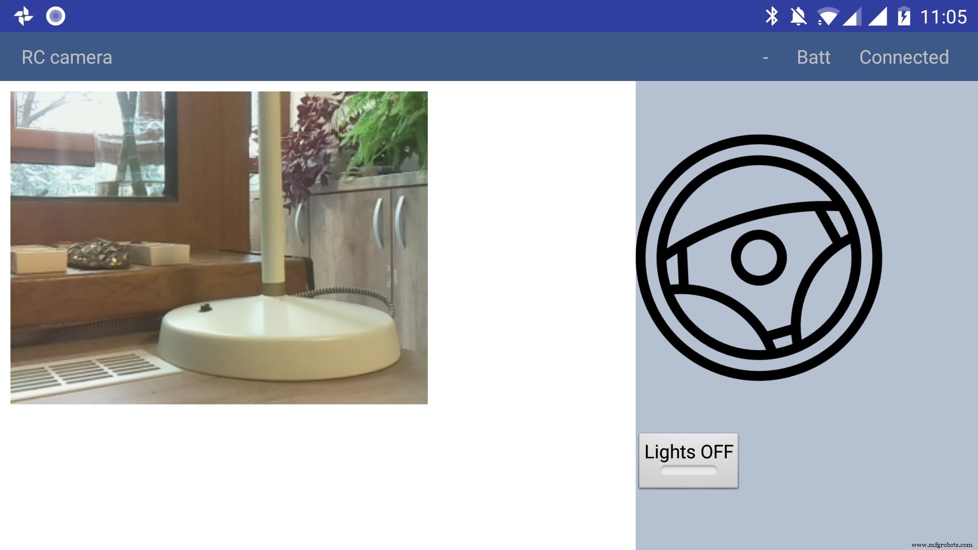
Using the app
The application has only a main screen, in the left of the screen the streamming image is displayed. On the right
there are the controls. The main control is a steering wheel, touch the steering wheel in the direction you wish the robot to move. Below the steering wheel there is a headlight button, touch it to toggle the light.
In the top right corner there is a text like :"- Batt Connected".
* First dash means no obstacles, if there is an obstacle in front or in the back of the robot it will be signaled with a small arrow pointing in front or in the back.
* The "Batt" status is not implemented yet.
* "Connected" means that MQTT server is connected so the robot can be used, the other possible value is "Disconnected"
Debugging can be done on multiple layers:
1. On the arduino layer
- Connect the FTDI adapter to the second serial line to the laptop (RX to pin 11 and TX to pin 10) and issue motor commands and light commands to see if the robot responds to these commands
- Double check the connections, if the motors are moving backwards reverse the both motor wires, if one motor is moving backwards reverse the it's wires
- Check if the arduino is connected properly to the H-bridge, check this link for more information
2. On the rasberry pi layer
- Check docker is running the two containers (mosquitto and python server)
pi@raspberrypi:~ $ docker ps CONTAINER ID IMAGE COMMAND CREATED STATUS PORTS NAMES 473a56da2230 dockercontainer_python-server "python /root/debu..." 9 months ago Up 4 hours dockercontainer_python-server_1 3e0b1933d310 robot-camera-mosquitto "/usr/bin/entry.sh..." 9 months ago Up 4 hours 0.0.0.0:1883->1883/tcp dockercontainer_mosquitto_1 - Check the processes are running on specified ports, you should look for 9090 (streamming) and 1883 (mosquitto)
pi@raspberrypi:~ $ netstat -nltp (Not all processes could be identified, non-owned process info will not be shown, you would have to be root to see it all.) Active Internet connections (only servers) Proto Recv-Q Send-Q Local Address Foreign Address State PID/Program name tcp 0 0 0.0.0.0:9090 0.0.0.0:* LISTEN - tcp 0 0 0.0.0.0:5900 0.0.0.0:* LISTEN - tcp 0 0 0.0.0.0:8080 0.0.0.0:* LISTEN - tcp 0 0 0.0.0.0:22 0.0.0.0:* LISTEN - tcp6 0 0 :::1883 :::* LISTEN - tcp6 0 0 :::5900 :::* LISTEN - tcp6 0 0 :::22 :::* LISTEN - - Check the serial port exists (it's the correct one) and it's specified in the project config.py
pi@raspberrypi:~ $ ls -l /dev/ttyS0 crw-rw---- 1 root dialout 4, 64 Jan 14 19:59 /dev/ttyS0 - Stop the docker process and manually connect to serial using picocom
Then issue motor and light commands directly to see if the robot responds
sudo systemctl start robot-camera.service picocom -b 9600 /dev/ttyS0 # now issue motor and light commands to test the robot - Check if the serial console is deactivated on the raspberry pi
- Check the streaming and MQTT are accessible outside the raspberry pi suing a mosquitto client (for MQTT) and checking the streaming in a web browser)
3. Android application layer
- Check all the necessary steps to enable the phone into debugging mode (check this out)
- Make sure you've set up the passwords and endpoints correctly in the passwords.xml
- Check the streaming and MQTT are accessible outside the raspberry pi suing a mosquitto client (for MQTT) and checking the streaming in a web browser)
- See the top right corner of the app and check for "Connected"
- Use the android debugger to check for errors
Step 8:Other Use Cases, Extending the Code
Another use case is a object following robot .The robot will follow an object of a specific color and size threshold
Check above for the video.
Because this is out of scope of this tutorial i'll just give you some hints:
First install dependencies using pip, the installation process will be quite slow
sudo pip3 install -r /home/pi/robot-camera-platform/navigation/requirements.txt - make sure python 3.x is installed though
- In navigation/config_navigation.py you'll find:
hsv_bounds =( (24, 86, 6), (77, 255, 255) ) object_size_threshold =(10, 100) HSV means hue saturation value, and for our color object detection to work it has a lower and an upper bound, our object color will have to be in this range to be detected. Here you can find a visual HSV object threshold detector.
Object size threshold means the smallest and the highest object radius size (in percents from width) which will be considered a detection.
- install and configure VNC (more information of how to install VNC here)
- Run the object tracking script in VNC graphical interface in a terminal. This will enable you to view the video, with a circle drawn over it. The circle means that the object has been detected.
python3 object_tracking.py colored-object --show-video OR Run the object tracking script with no video output:
python3 object_tracking.py colored-object I think the main advantage of this platform is versatility , it can be adapted easily to other interesting usages, some of my ideas:
- Following a person by face recognition
- Patrolling and reporting movement
- Replace the wifi with a 3G modem and the robot can be controlled outside, maybe exploring dangerous zones
This being a very complex project i assume that there will be errors, i will appreciate if you ask me anything in the comments area.
If you like my project please my youtube channel for more interesting stuff.
<섹션 클래스="섹션 컨테이너 섹션 축소 가능" id="코드">제조공정
구성품 및 소모품 Arduino UNO × 1 HC-05 블루투스 모듈 × 1 카메라 OV7670 × 1 Arduino TFT 실드 × 1 이 프로젝트 정보 오늘날에는 카메라, 무선 장치 및 기타 기술 발전이 있는 휴대 전화를 사용하는 사람을 거의 놀라게 할 수 없습니다. Arduino 플랫폼 덕분에 수백만 명의 사람들이 전자 및 프로그래밍의 놀라운 세계를 발견했습니다. 100, 500 지침은 블루투스를 통해 휴대 전화와 Arduino간에
이 Arduino IR Tutorial에서는 TV 리모컨과 Arduino를 사용하여 전자 장치를 제어하는 방법을 배웁니다. 간단한 LED 제어부터 DC Fan 속도 제어, 고전압 가전 제어까지 몇 가지 예를 들어 보겠습니다. 다음 동영상을 보거나 아래에 작성된 튜토리얼을 읽을 수 있습니다. 작동 방식 버튼을 눌렀을 때 TV 리모컨 앞의 LED가 깜박이는 것을 볼 수 있습니다. 실제로 이것은 적외선이며 사람의 눈에는 보이지 않기 때문에 카메라를 통해서만 볼 수 있습니다. 따라서 깜박임은 버튼을 누를 때 적외선 LED가 적