

제조공정

산업 제조
 |
| × | 1 | |||
 |
| × | 1 | |||
 |
| × | 1 | |||
 |
| × | 4 | |||
 |
| × | 1 | |||
 |
| × | 1 | |||
 |
| × | 1 | |||
 |
| × | 1 | |||
 |
| × | 1 | |||
 |
| × | 1 |
| |
| |||
| |
|
 |
| |||
 |
|
소개
저는 MIT의 개방형 농업 이니셔티브(Open Agriculture Initiative)의 책임자인 Caleb Harper가 This Computer Will Grow Your Food in the Future라는 주제로 발표한 TED Talk about Digital Farming을 보고 큰 영감을 받았습니다. . 그의 강연에서 나에게 정말 영감을 준 가장 중요한 질문은 "만약 우리가 세계 어느 곳에서나 맛있고 영양이 풍부한 음식을 실내에서 키울 수 있다면 어떨까요?"였습니다. 그리고 여기에서 아이디어가 탄생했습니다!
그래서 제가 하려고 하는 것은 상자나 인큐베이터 같은 것입니다. 성장에 필요한 이상적인 기후 조건을 만들어 식물이 필요로 하는 정확한 양의 빛과 영양분을 제공할 수 있습니다. 저는 태양광 에뮬레이터, 관개 시스템, 실내 온도 조절기를 하나의 우아하고 현대적인 디자인으로 만들고 싶습니다.

다음 기술을 구현하여 원하는 결과를 얻을 계획입니다.
LED 조명 성장 - 식물의 엽록소는 주로 450nm 및 650nm로 표시되는 두 가지 파장에만 반응합니다. 제가 사용할 계획인 LED 시스템은 적색과 청색 LED 조명의 조합을 사용하여 식물과 개화 성장 모두에 도움이 되는 완벽한 조화를 제공할 것입니다.
초음파 분무기 (안개 제조기) - 비료가 주입된 미스트를 통해 식물에 물을 주는 에어로포닉스(FogPonics)라고 하는 최근에 알게 된 새로운 관개 방법을 사용하고 싶습니다.
자동 영양 공급 - 이 시스템은 식물이 필요할 때 정확히 자동으로 영양분을 공급합니다.
물 감지 시스템 - 내 시스템에 pH 및 TDS(Total Dissolved Solids) 센서를 장착하여 식물에 가장 적합한 저수지의 균형 잡힌 pH 값을 유지하고 영양분을 투여할 시기를 알고 경고하고 싶습니다.
물 교환 시스템 - 시스템에는 자동 물 교환을 위한 연결 장치가 있어야 합니다. 이 프로세스를 쉽게 만들고 버튼 클릭으로 제어하고 싶습니다.
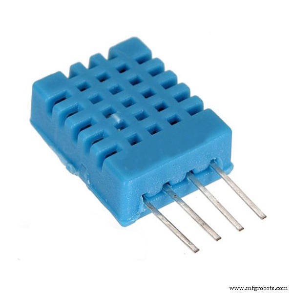
에어컨트롤 시스템 - 시스템 내부의 온도와 습도를 1도까지 정밀하게 제어할 수 있습니다. 이면의 기술에는 DHT22 또는 DHT11과 같은 온도/습도 센서를 사용하여 데이터를 수신하고 코일이 있는 팬을 사용하여 그에 따라 조절하는 것이 포함됩니다.
모바일 앱 - 정말 태어나서 처음으로 앱을 만들고 싶어요! 이 앱은 통계를 추적하고 소셜 미디어에서 성장 진행 상황을 공유하기 위해 pH 수준, 온도, 습도, 영양소, ppm 등에 대한 실시간 정보와 시간 경과에 따른 그래프 표현을 포함해야 합니다. 또한 시스템에 내 의미가 필요할 때 알려주는 지능형 경고를 구현하고 싶습니다. 나는 또한 내 전화에서 데이터 표현을 수신할 뿐만 아니라 시스템 내부의 기후 조건을 설정할 수 있기를 원합니다!
유감스럽게도 제가 이런 종류의 아이디어를 처음 내놓은 것은 아니지만 창의적인 아이디어를 생각해 내는 가장 좋은 방법은 기존 아이디어를 개선하는 것입니다!
시장에 유사한 프로젝트가 몇 개 있지만, 모든 개별적인 장점에도 불구하고 너무 많은 공간을 차지하거나 너무 작거나 너무 비싸고 한 번에 한 작물만 재배하는 등의 몇 가지 단점도 있습니다. 저는 많은 일을 했습니다. 사용 가능한 프로젝트의 장단점을 면밀히 조사하고 분석하고 시장 반응을 고려하여 단점을 줄이고 최고의 기능만 구현하는 새로운 고급 오픈 소스 시스템을 제시하고 싶습니다.
아주 야심차지 않나요? 하지만 한 번 해보자
실험
식물을 다루는 것은 매우 시간이 많이 걸립니다! 일반적으로 성장하는 데 몇 주에서 몇 달이 걸리며 저는 이에 대비해야 합니다!
마지막 프로젝트를 위해 무엇을 만들고 싶은지 이미 알고 있기 때문에 미리 처리하고 마지막 순간을 위해 모든 것을 남겨 두지 않아야합니다. 그렇기 때문에 최대한 빨리 테스트와 실험을 시작하겠습니다!
가장 먼저 알고 싶은 것은 영양분이 풍부한 미스트를 사용하여 식물을 재배한다는 사실입니다. LED 조명 성장 토양과 자연광에서 기존 시스템보다 우수합니다! 이론상으로는 정확히 맞아야 하지만 해보기 전까지는 아무 것도 믿지 않습니다!
그래서 나는 약간의 시간이 필요하며 식물을 여러 그룹으로 나누는 나만의 실험을 시작하기로 결정했습니다.
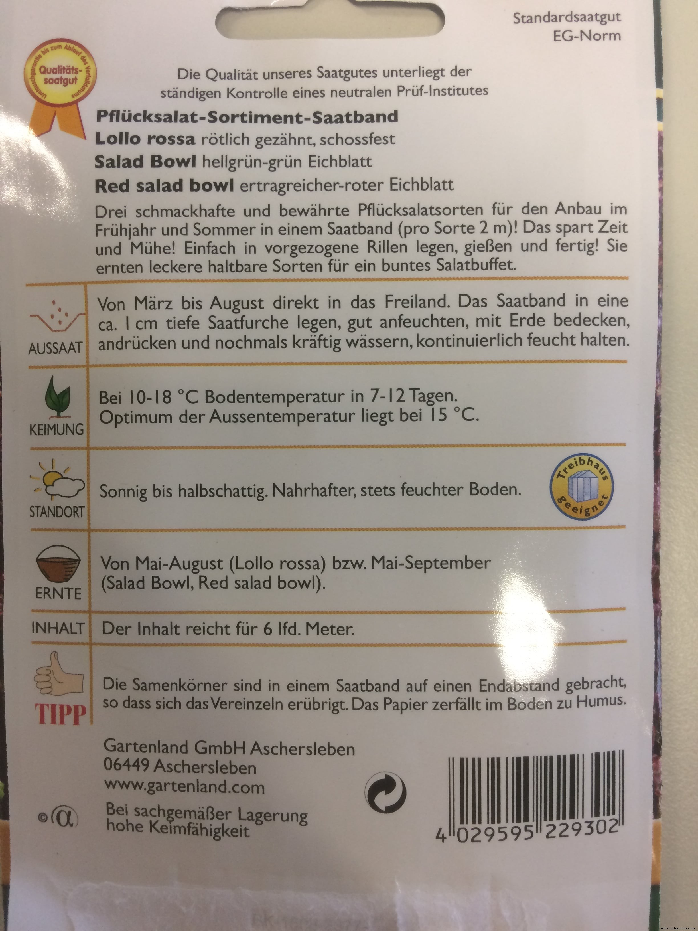
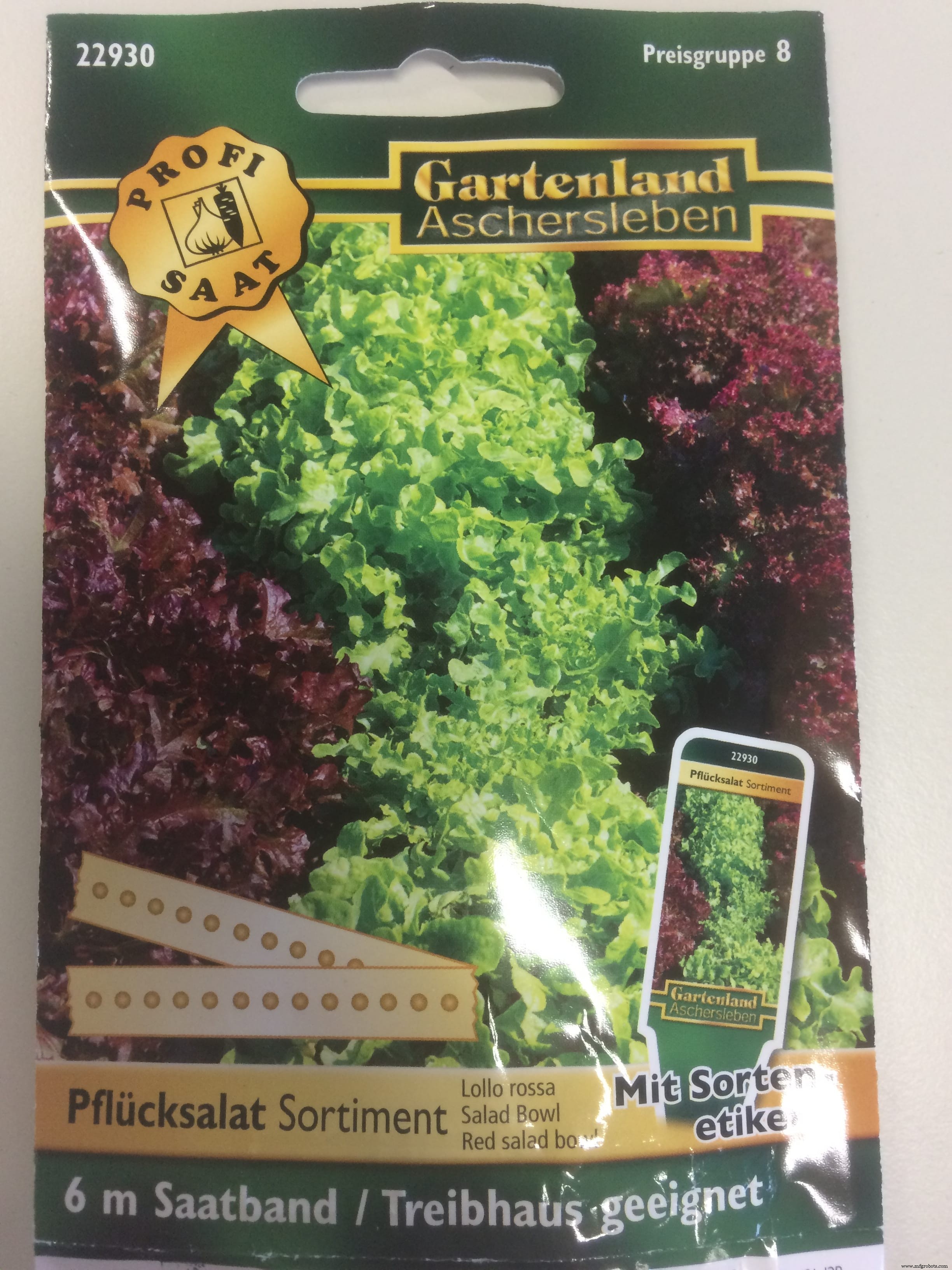
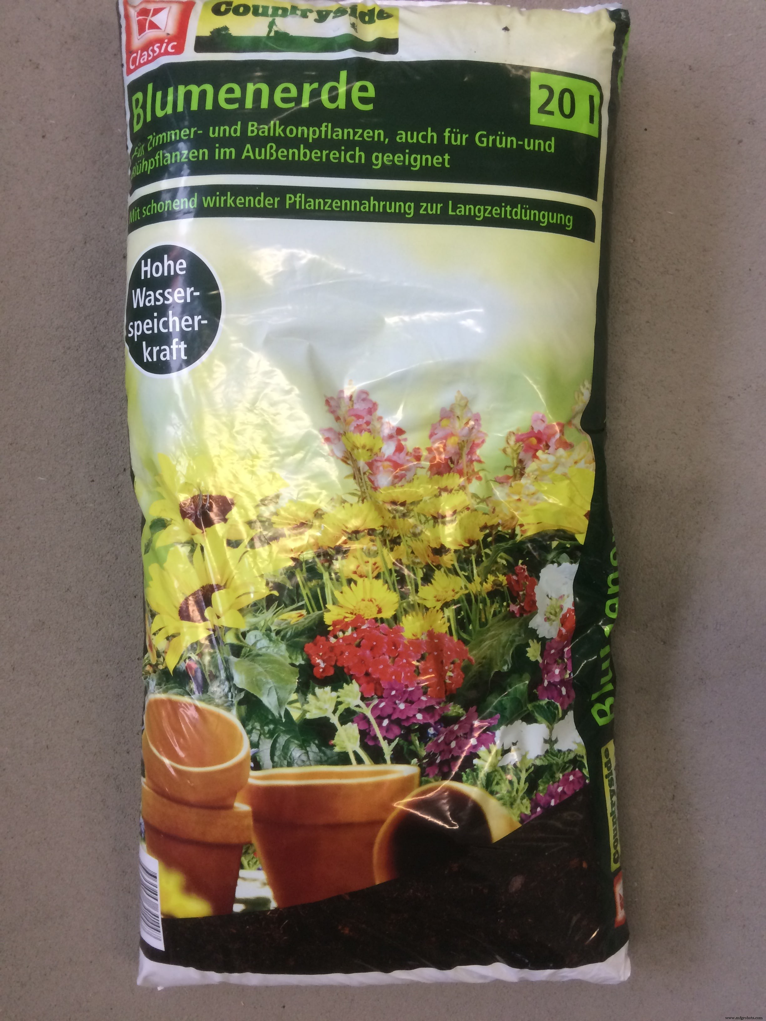
<울>지역 독일 상점 Kaufland의 식물 부서에서 혼합 허브의 씨앗을 샀습니다. 이것들은 내 테스트 아기가 될 것입니다 :p
난생 처음으로 뭔가를 심었다 :D 내가 뭔가를 잘못했다고 나를 판단하지 마십시오!)
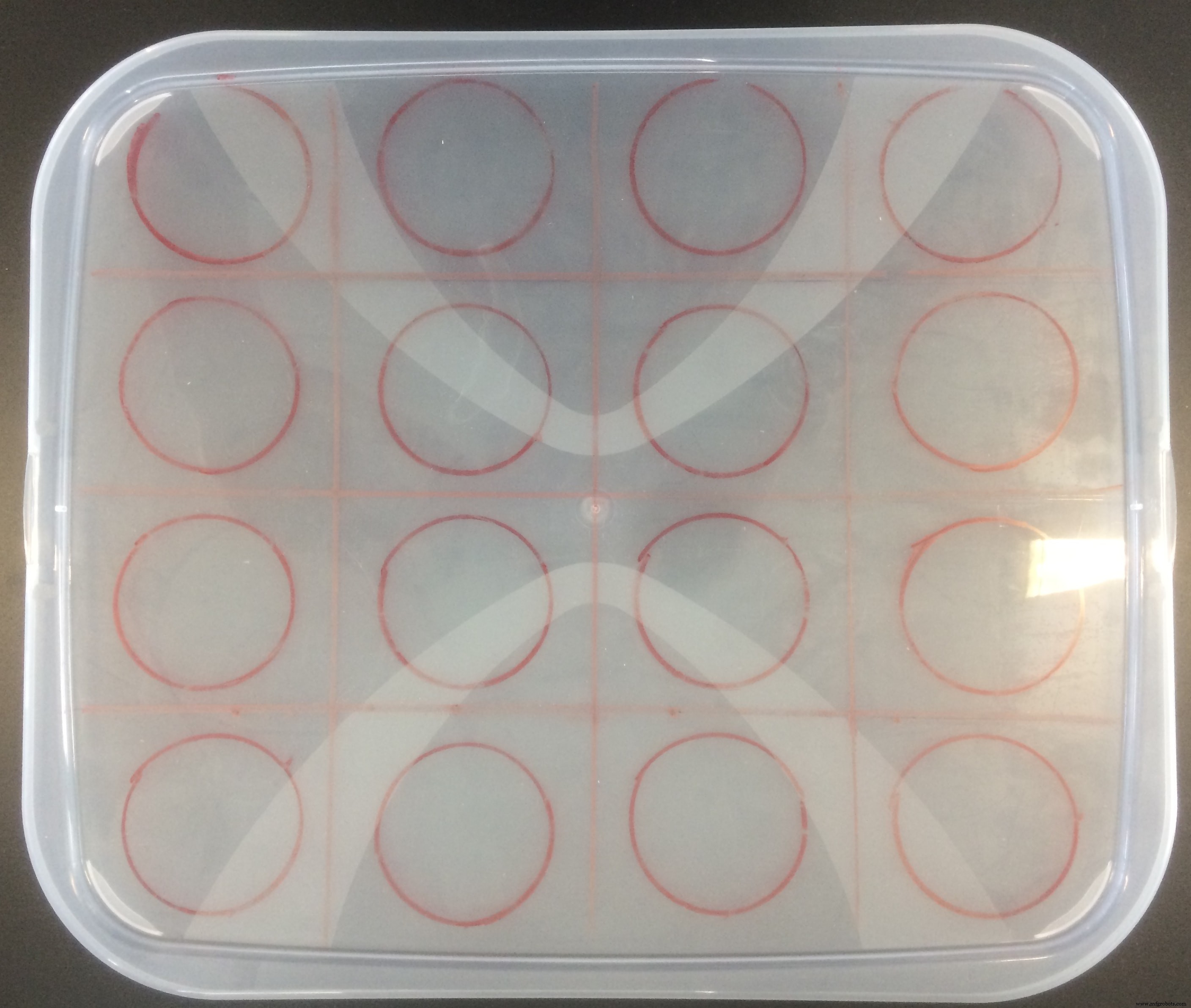
이전에 여러 튜토리얼을 확인했고 씨앗을 먼저 발아시켜야한다는 것을 배웠습니다. 나는 씨앗을 넣을 플라스틱 용기를 얻었고 종이 타월로 덮었습니다. 이 단계에서는 거의 100%의 습도가 필요하기 때문에 스프레이를 사용하여 종이 타월에 물을 주고 용기를 비닐 봉지로 덮어 물이 증발하지 않도록 했습니다.
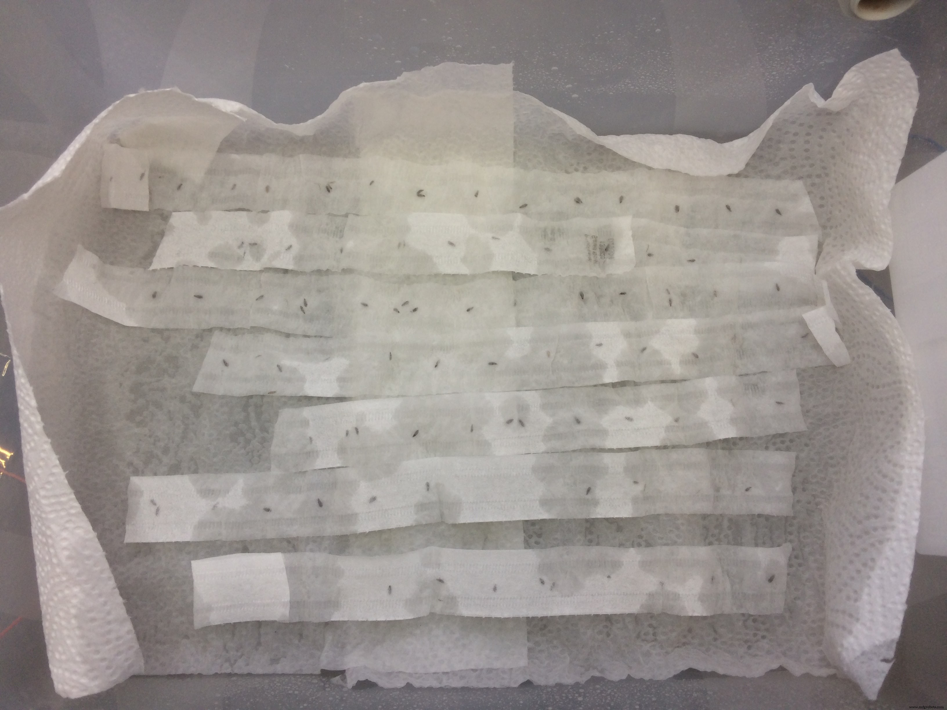
씨앗을 1.5주 방치했는데, 용기를 열어보고 정말 놀랐어요!
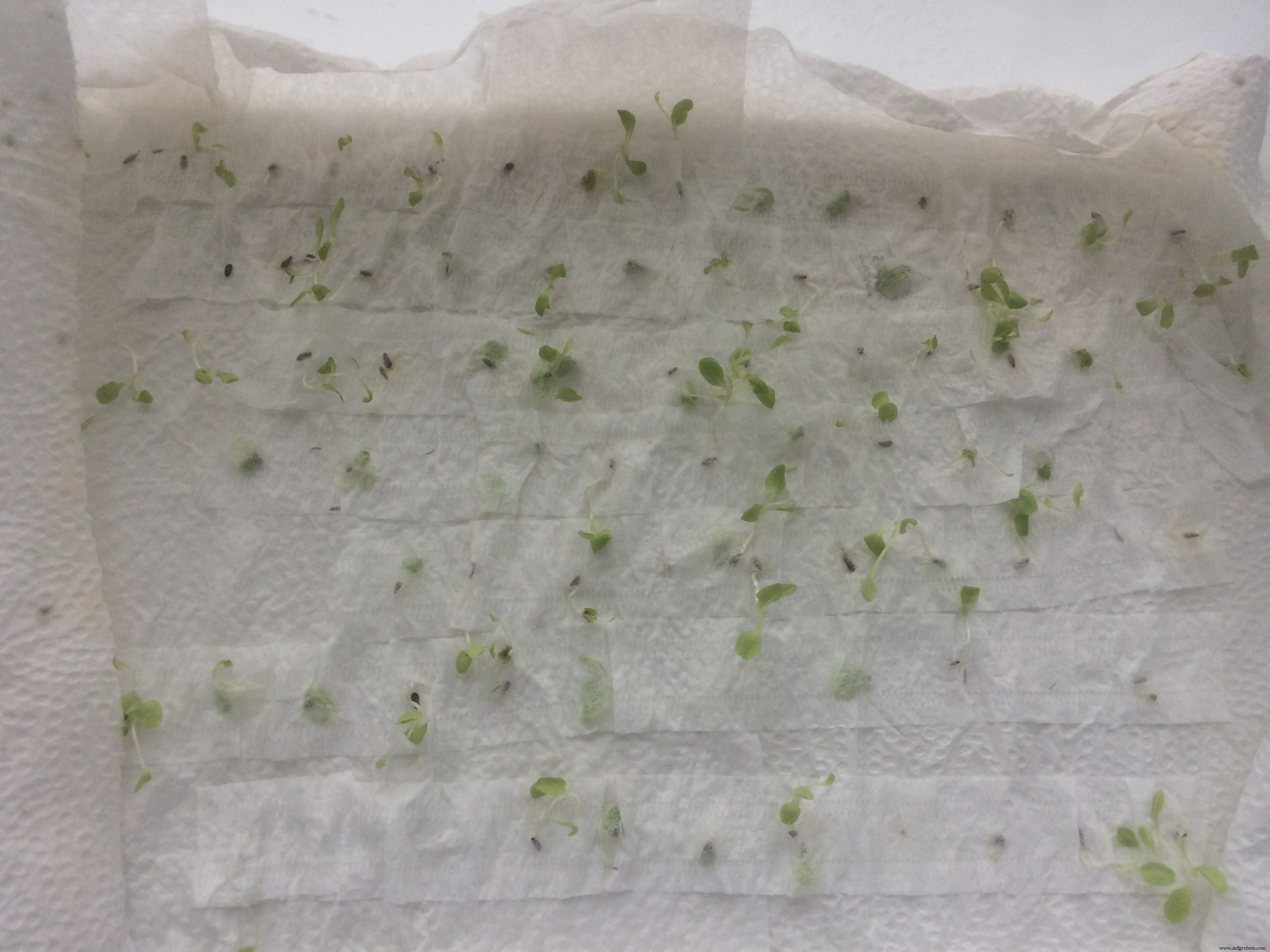
거의 모든 씨앗이 발아했습니다! 아이처럼 행복했어요)
다음으로 나는 가장 좋은 작은 식물, 가장 두꺼운 줄기를 가지고 있고 전체적으로 더 크고 더 좋아 보이는 식물을 선택해야 했습니다.
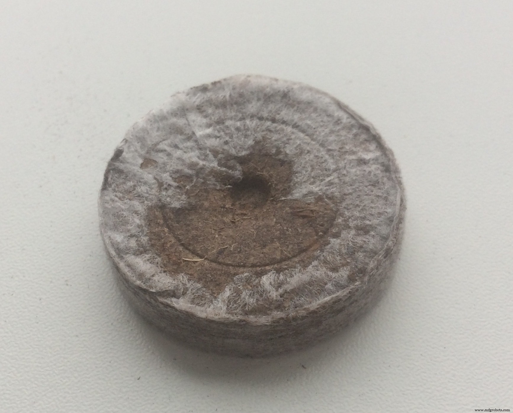
내가 팔로우한 튜토리얼(YouTube 블로거)에서 그 사람은 "두 번째 잎"이 나올 때까지 모든 유형의 배지에 작은 식물을 심을 것을 권장했습니다. Amazon에서 코코넛 야자 껍질을 주문했습니다. . 그들은 유기물이며 토양과 유사한 특성을 가지고 있으며 멋진 점은 알갱이에 물을 주면 크기가 6배 더 커집니다.
나는 또한 심기 위해 특별히 분리기가 있는 상자를 구입했습니다! 나는 단지 2유로에 그것을 얻었고, 이것은 일을 더 체계적으로 만들었습니다. 나는 코코넛 알갱이를 상자의 분리기 안에 넣고 완전히 수분이 될 때까지 물을 주고 중간에 작은 식물을 놓고 상자 키트와 함께 제공된 투명한 플라스틱 조각으로 상자를 덮었습니다.
내 작은 온실은 다음과 같았습니다.
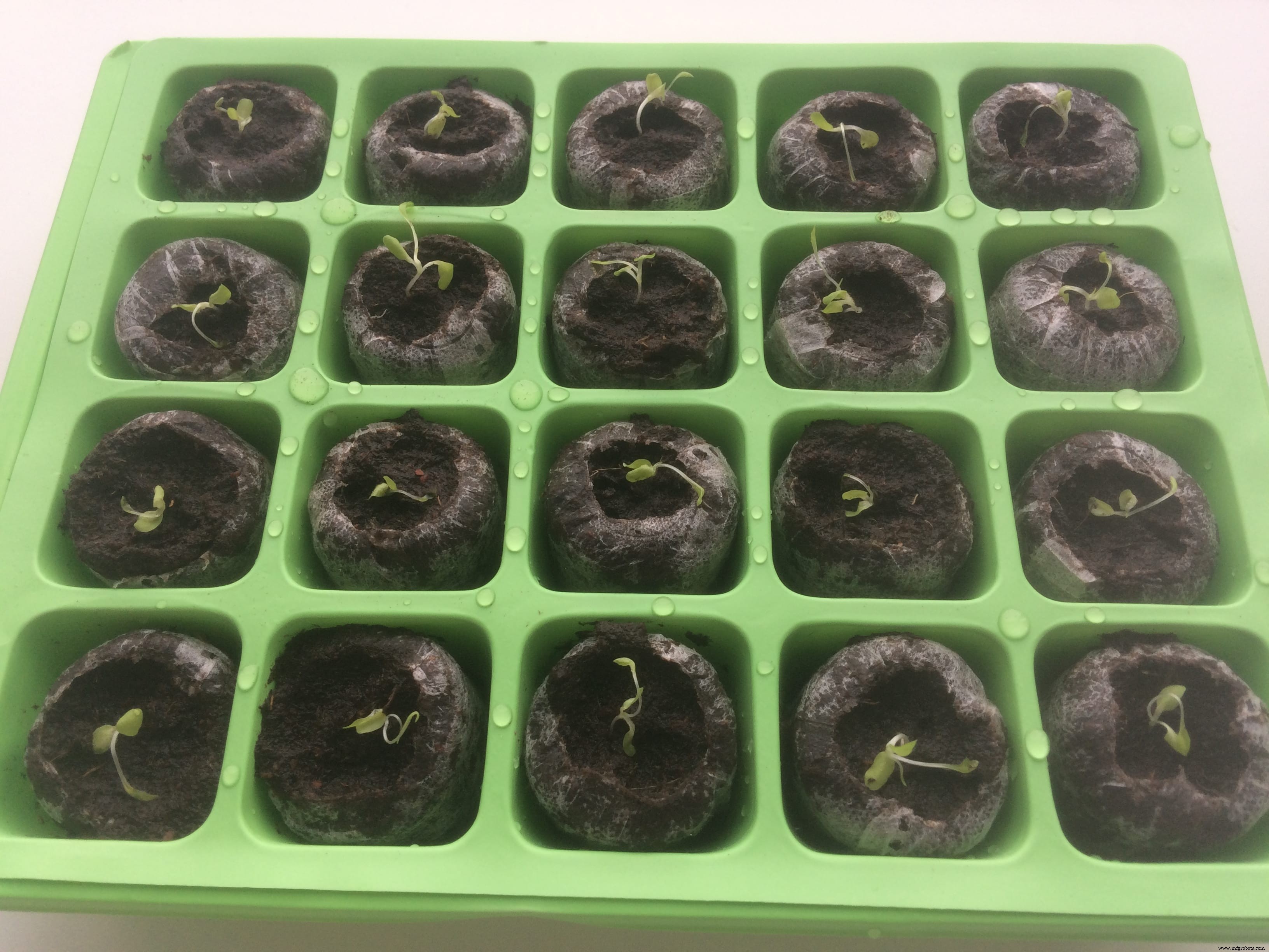
상자를 닫고 일주일 동안 그대로 두었습니다!
그리고 열어보고 또 놀랐어요! 그들은 실제로 더 커졌습니다! 식물을 키울 수 있다는 것은 상상도 할 수 없었고, 제 자신을 거의 돌볼 수 없었습니다 :D
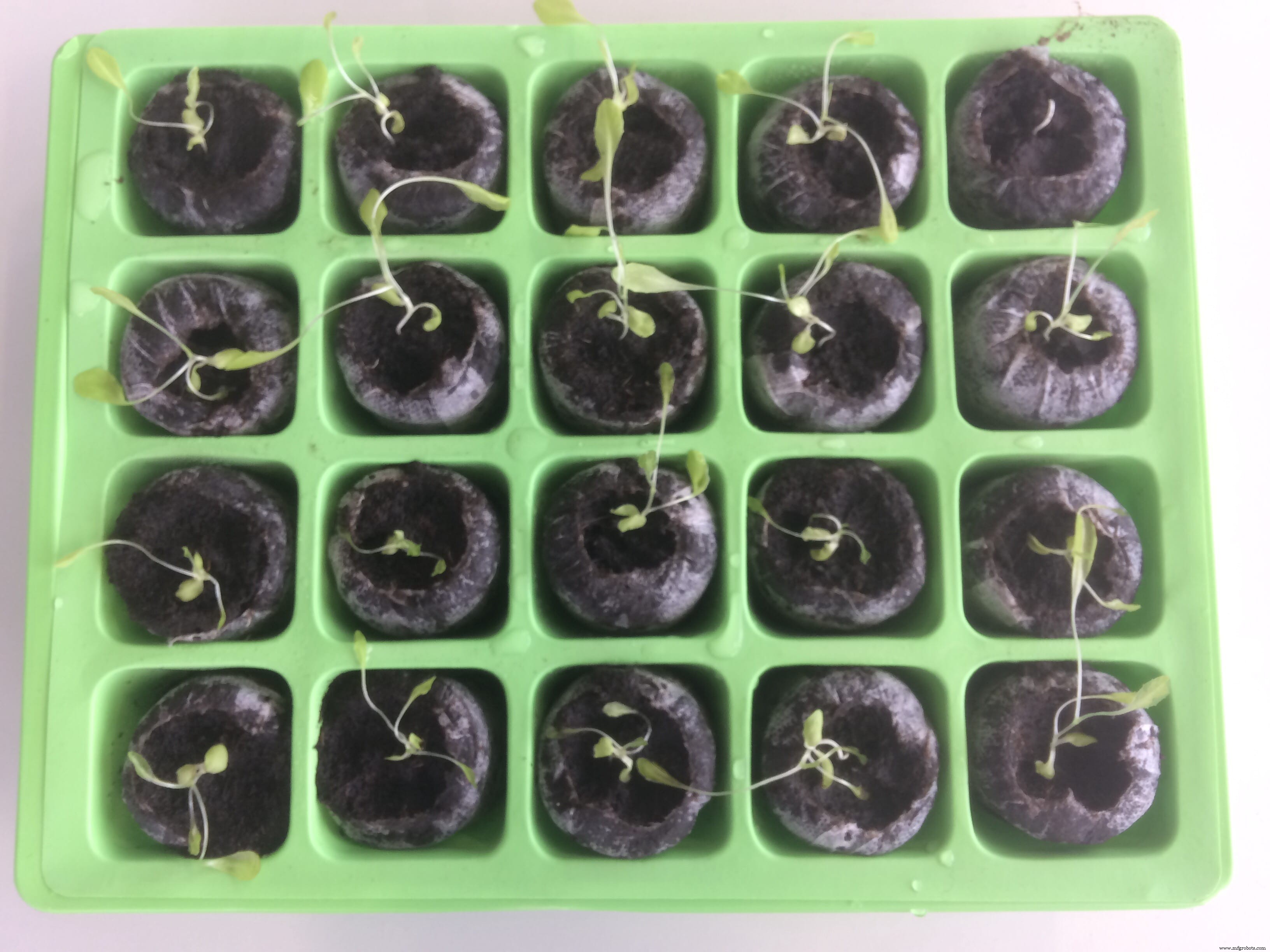
1주일 후, 그 차이가 눈에 띕니다!
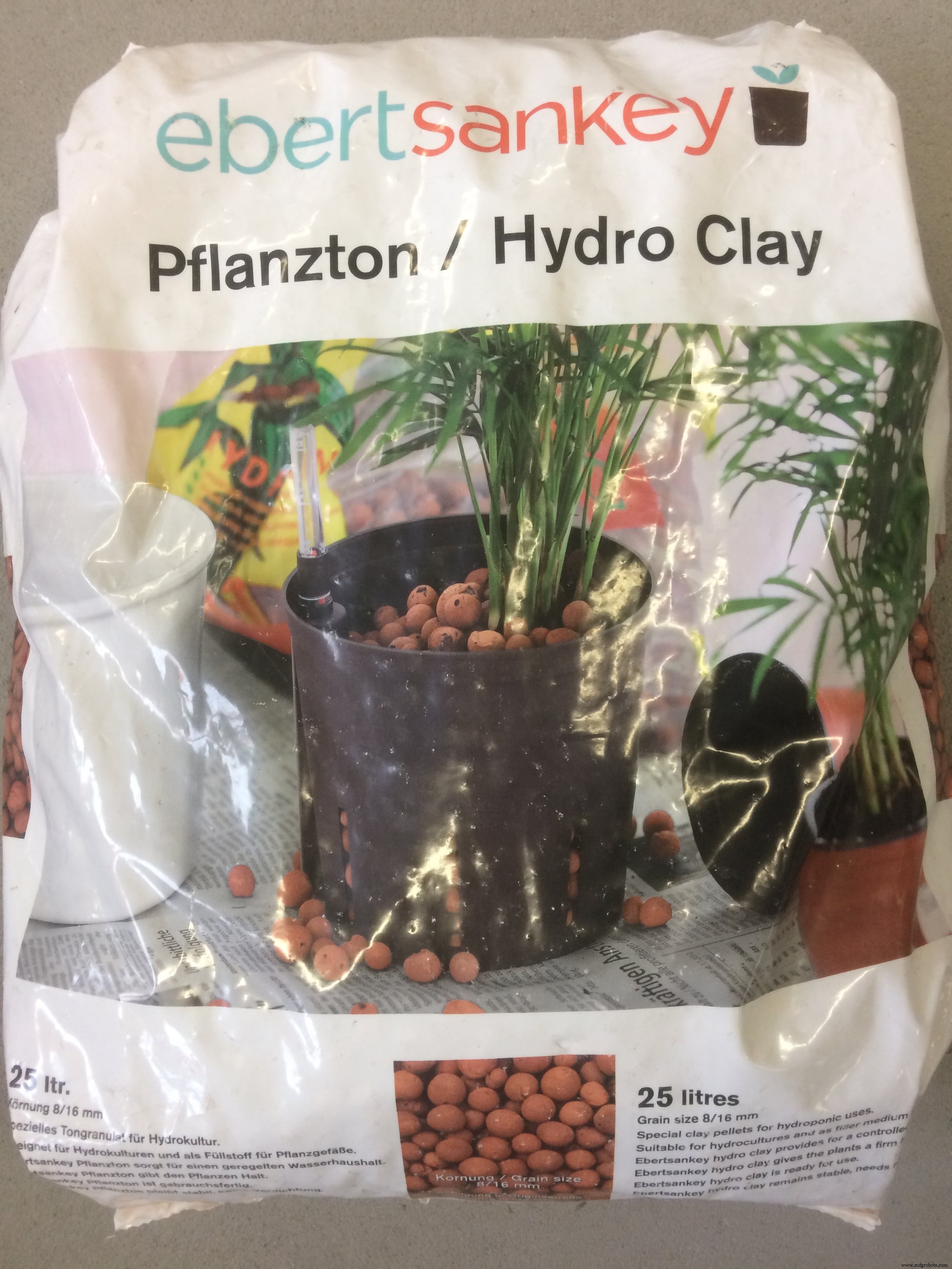
이제 첫 번째 뿌리가 보이면 흙과 점토 공에 넣고 안개 실험을 시작할 수 있습니다!
Computer-Aided Design 주간에는 식물을 놓을 때 사용했던 그물 컵을 디자인했습니다.
또한 지역 상점에서 필요한 대략적인 치수의 플라스틱 용기를 구입하고 드릴 구멍을 스케치했습니다!
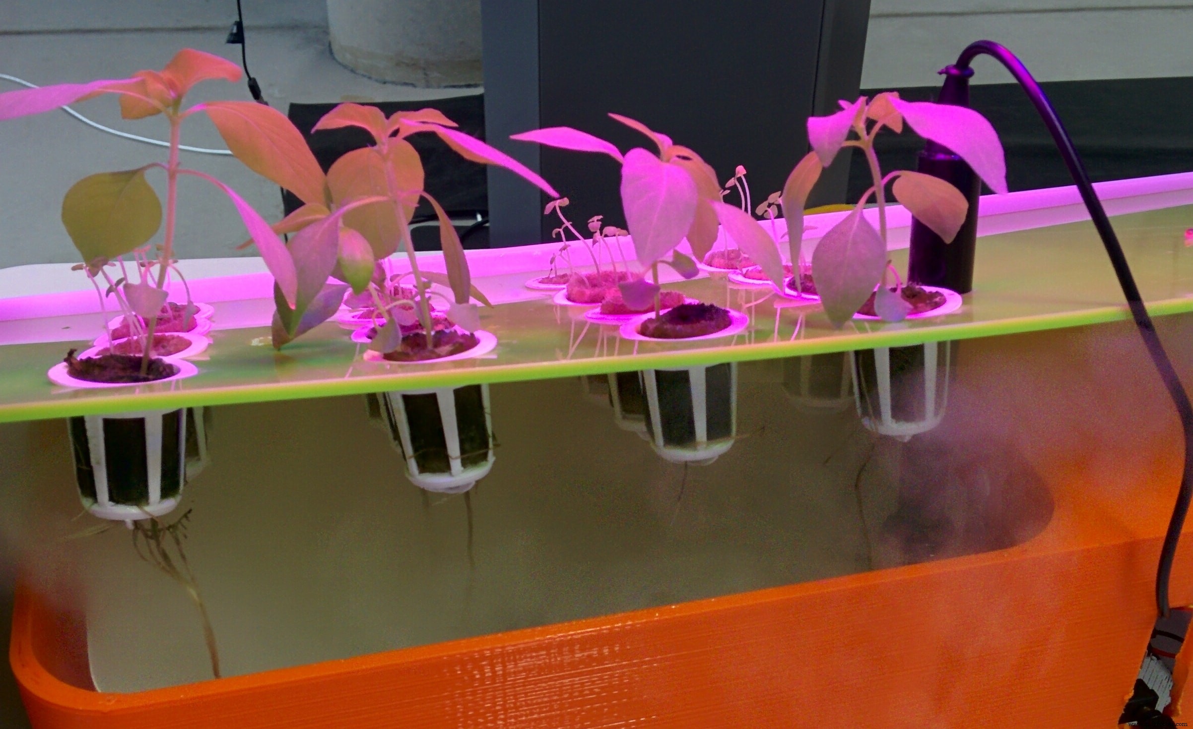
여기 제가 조립한 테스트 시스템이 있습니다. 코코넛 알갱이 안에 있는 식물과 흙, 흙이 있습니다!
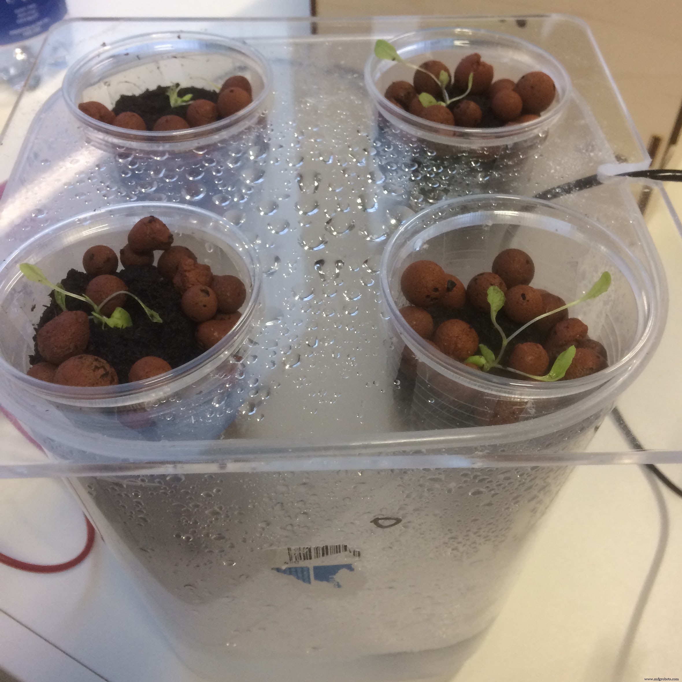
솔직히 결과가 더 좋을 수 있습니다 :D
내 안개 시스템에서 살아남은 식물은 거의 없었습니다. 내 추측은 성장 매체 때문입니다! 안개는 진흙 공을 젖게 할 만큼 강하지 않으며 흙도 아닙니다.
부활절 방학!
부활절 방학 동안 나는 아무것도 하지 않았고, 연구실이 문을 닫았기 때문에 모든 시스템도 꺼져 있었다. 그래서 내 식물이 모두 죽었습니다.
새로운 마음으로 다른 시스템을 만들기로 마음먹었지만 이번에는 이전 관찰을 바탕으로 다른 재배 매체를 사용했습니다.
이 시스템을 위해 선택한 성장 매체는 Rock Wool입니다. . 동네 IKEA 매장에서 샀어요. 나는 또한 그들의 부서에서 씨앗 몇 개를 샀습니다.

그리고 나는 일주일 동안 발아를 위해 암면에 새 씨앗을 넣었습니다!
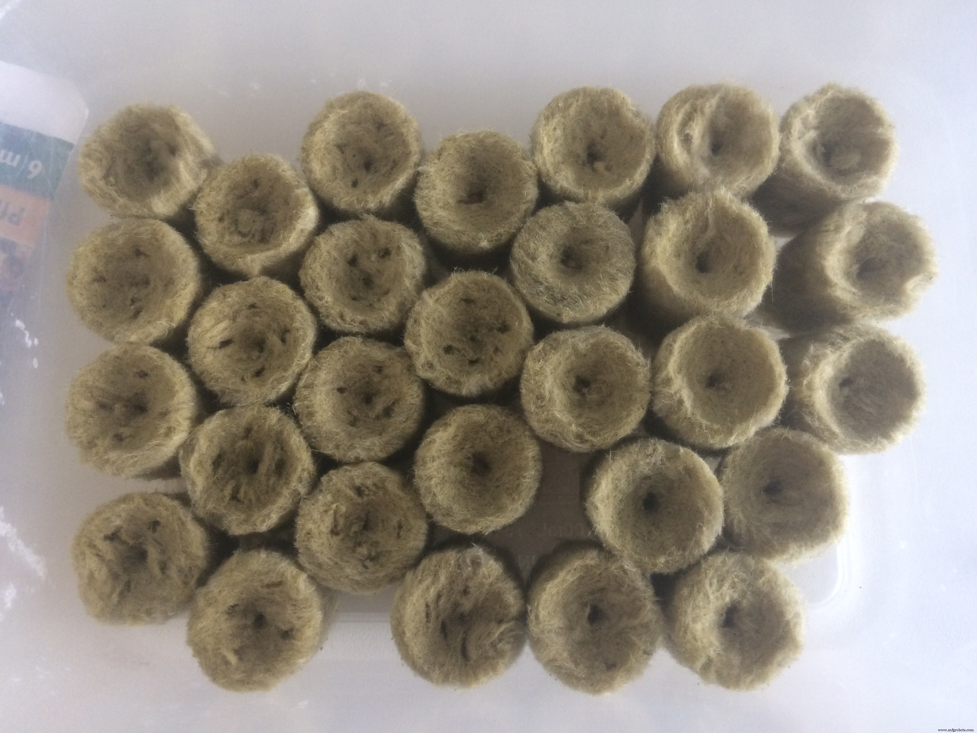
일주일 후 나는 내 상자를 확인하고 한 종류의 씨앗은 성공했고 다른 씨앗은 실패했음을 발견했습니다! 시간이 부족해서 발아한 씨앗으로 진행했습니다
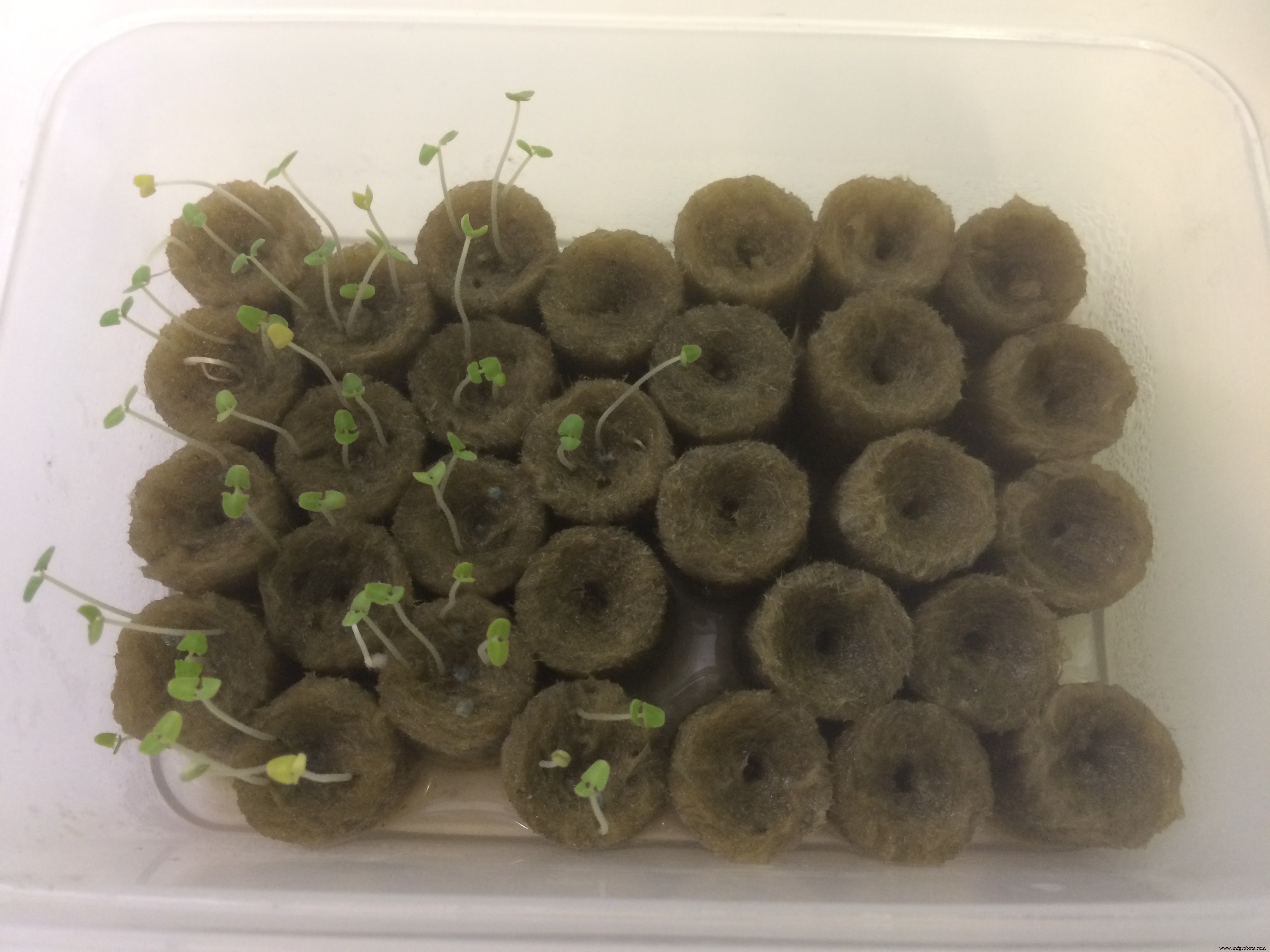
그 동안 나는 또 다른 안개 시스템을 설정하고 작업 시간을 늘리려고 노력할 것입니다. 안개를 사용하여 씨앗을 발아시킬 수 있다면 안개만!
다양한 매개변수와 설정을 계속 실험하고 어디까지 도달할 수 있는지 확인하겠습니다!)
전자 설계 및 생산
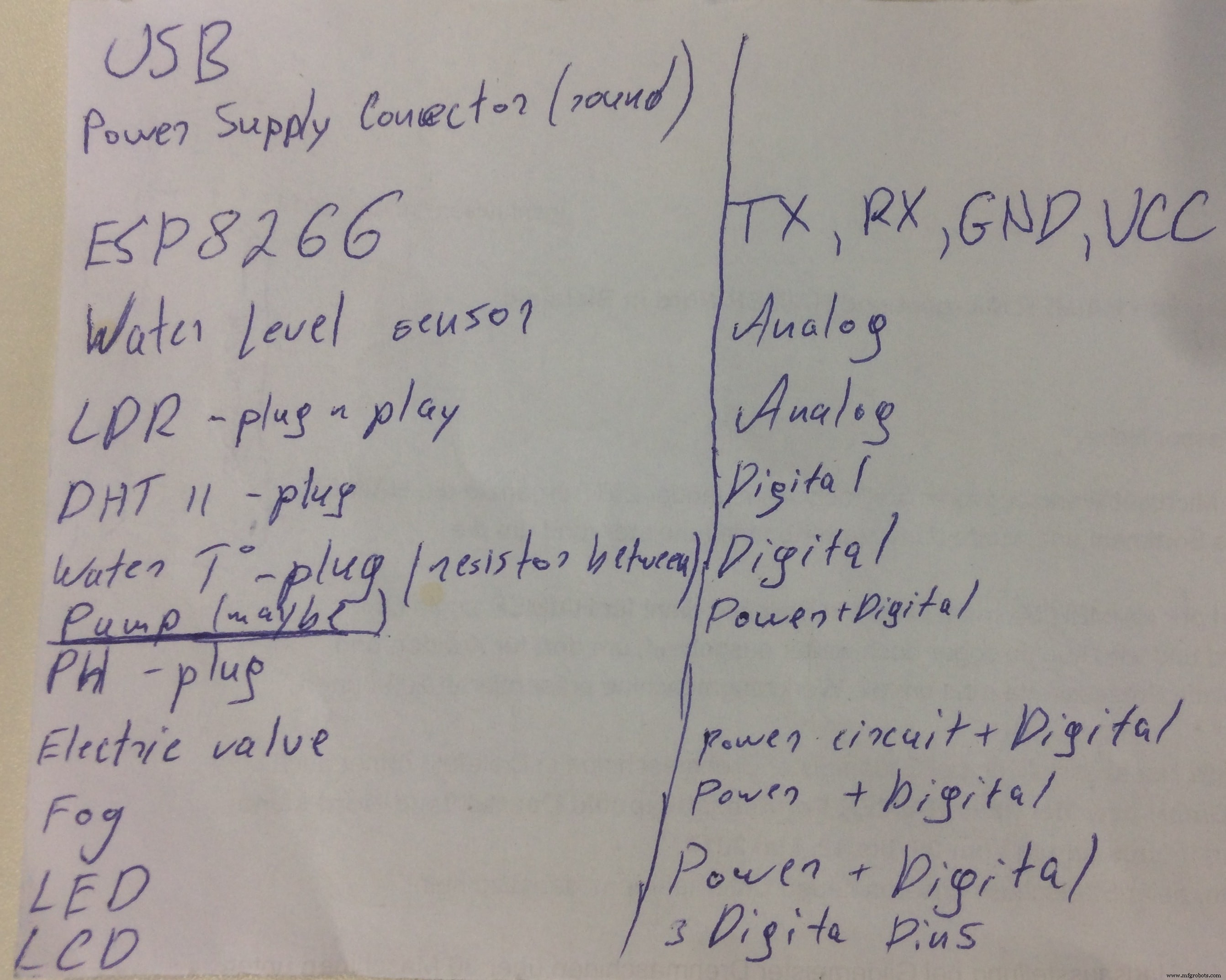
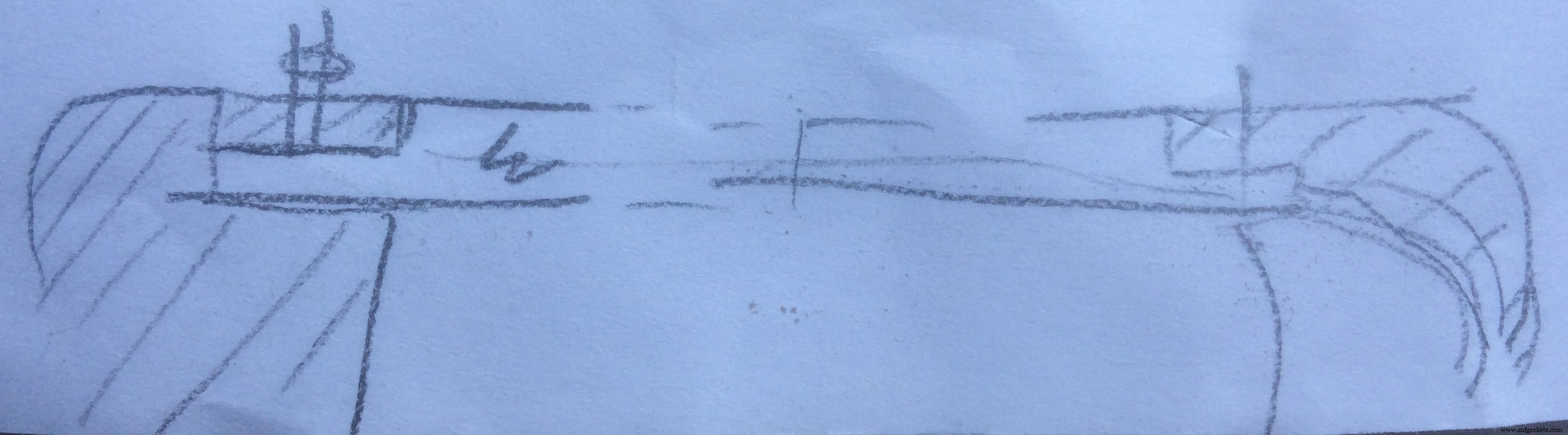
최종 보드 디자인에 뛰어들기 전에 저는 보드가 구현하고 충족해야 하는 모든 기능과 요구 사항을 종이에 그리기 위해 자리에 앉았습니다! 또한 더 나은 추정을 위해 그리고 최종 마이크로프로세서가 어느 것이 될지 결정하기 위해 얼마나 많은 핀이 사용될 것인지 추적합니다.
다음은 칠판에 있어야 할 내용의 스케치입니다.
사용할 보드의 최종 선택은 satshakit Daniele Ingrassia 및 FABLEO 조나단 그린햄 작성
satshakit은 100% Arduino IDE 및 라이브러리 호환 가능하고 제작 가능한 오픈 소스 보드이며 Fabkit의 개선된 버전이기도 합니다.
Fabkit의 주요 개선 사항 및 기능은 다음과 같습니다. <울>
반면에 FabLeo에는 하드웨어 USB와 함께 매우 유사한 기능이 있습니다! 이미 ATmega328p를 사용했기 때문에 새로운 것을 시도해보고 싶었고 FabLeo 디자인을 시작점으로 사용하기로 결정했습니다.
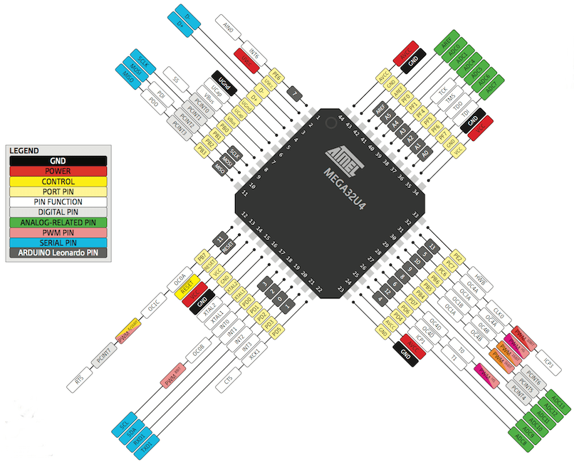
내 성경 이 할당에 대한 #1 가이드는 ATmega32u4 핀아웃이었습니다.
보드를 디자인하기 위해 내가 사용할 소프트웨어는 EAGLE입니다. (Easy Applicable Graphical Layout Editor)는 유연하고 확장 가능한 EDA 회로도 캡처, PCB 레이아웃, 자동 라우터 및 CAM 프로그램입니다. EAGLE은 프리웨어 라이선스와 웹에서 풍부한 구성 요소 라이브러리 가용성으로 인해 애호가들 사이에서 인기가 있습니다.
Eagle에는 보드를 디자인하는 데 동시에 사용되는 두 개의 창이 있습니다.
<울>EAGLE을 설치한 후 가장 먼저 하고 싶은 일은 새 Schematic 만들기입니다. . 전자 회로도는 회로를 나타내는 도면입니다. 기호를 사용하여 실제 전자 부품을 나타냅니다. 가장 기본적인 기호는 단순히 선으로 표시되는 단순한 도체(트레이스)입니다. 와이어가 다이어그램으로 연결되면 교차점에 점으로 표시됩니다.
구성 요소를 회로도에 배치하려면 특수 라이브러리를 다운로드하여 사용해야 합니다. . Eagle에는 우리가 사용할 수 있는 많은 구성 요소 라이브러리가 내장되어 있습니다. 팹 네트워크는 또한 지속적으로 업데이트되는 라이브러리를 유지 관리합니다.
fab.lbr
라이브러리를 설치하려면 EAGLE 환경에서 상단 도구 모음으로 이동하여 Library를 선택합니다. 메뉴. 그런 다음 사용을 선택합니다. .lbr을 엽니다. 방금 다운로드한 파일입니다.
이제 구성요소 추가로 이동할 수 있습니다. 라이브러리를 선택하고 배치할 구성 요소를 선택합니다.
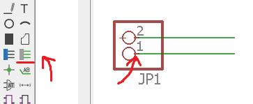
회로도에 모든 구성 요소를 배치한 경우 각 구성 요소를 마이크로프로세서의 핀에 연결해야 합니다. EAGLE 왼쪽 메뉴에서 Net을 클릭합니다. , 녹색 선을 그리고 핀을 연결할 수 있는 명령입니다. 중요한 것은 핀의 작은 선부터 연결을 시작하는 것입니다(그림에 표시했습니다)
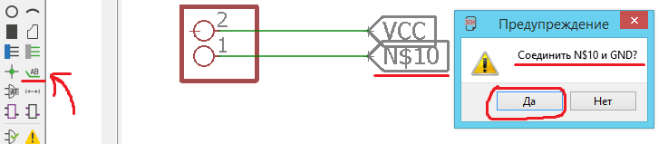
다중 연결을 피하기 위해 레이블을 사용하겠습니다. . EAGLE 왼쪽 메뉴에서 라벨 추가를 누릅니다. 내 연결 라인의 끝에 추가하십시오. 오른쪽 클릭을 누르면 그런 다음 이름을 선택하십시오. , 나는 마이크로 프로세서 핀에 사용한 것과 같은 이름을 레이블에 부여하고 이러한 방식으로 연결할 수 있습니다!
모든 작업을 올바르게 수행했다면 다음과 같은 메시지가 표시되어야 합니다. 레이블(N$10)을 GND와 연결하시겠습니까?
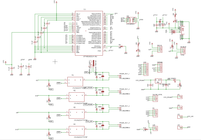
이 단계에서 화학에서 중요한 것은 Logic 모든 연결의 모양이 아니라. 모든 구성 요소를 배치하고 논리적으로 연결한 후의 모습은 다음과 같습니다.
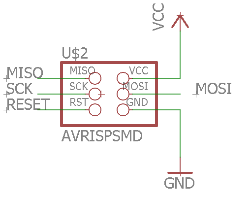
AVRISP를 추가했습니다. 핀 헤더를 만들고 커넥터의 순서에 따라 배치합니다. 이 핀은 내 보드를 프로그래밍하는 데 사용됩니다.
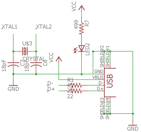
다음은 USB의 회로도입니다. 수정과 함께 회로
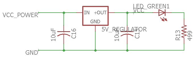
전압 조정기도 추가했습니다. 입력 12V를 5V로 변환하여 전체 보드에 전원을 공급하는 회로
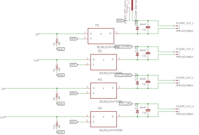
이 보드의 중요한 기능 중 하나는 MOSFET입니다. 회로 중 4개를 추가했는데 3개는 입력(12V)에 직접 연결되고 하나는 승압 전압 조정기에 연결됩니다. 마지막은 24V에서 작동하는 안개에 전원을 공급하는 데 사용됩니다.
모든 연결을 다시 확인한 후 다음 단계인 보드 레이아웃으로 진행할 수 있습니다. . 상단 메뉴에서 Generate/Switch to Board를 누릅니다. .
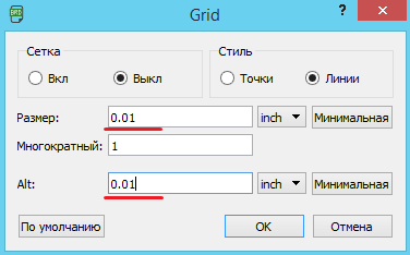
가장 먼저 하는 일은 Grid를 늘리는 것입니다. 해결. 보기로 이동합니다. 메뉴를 누르고 Grid를 누릅니다. , 값을 0.01로 변경 . 이렇게 하면 경로 선을 그릴 때 더 정확해집니다.
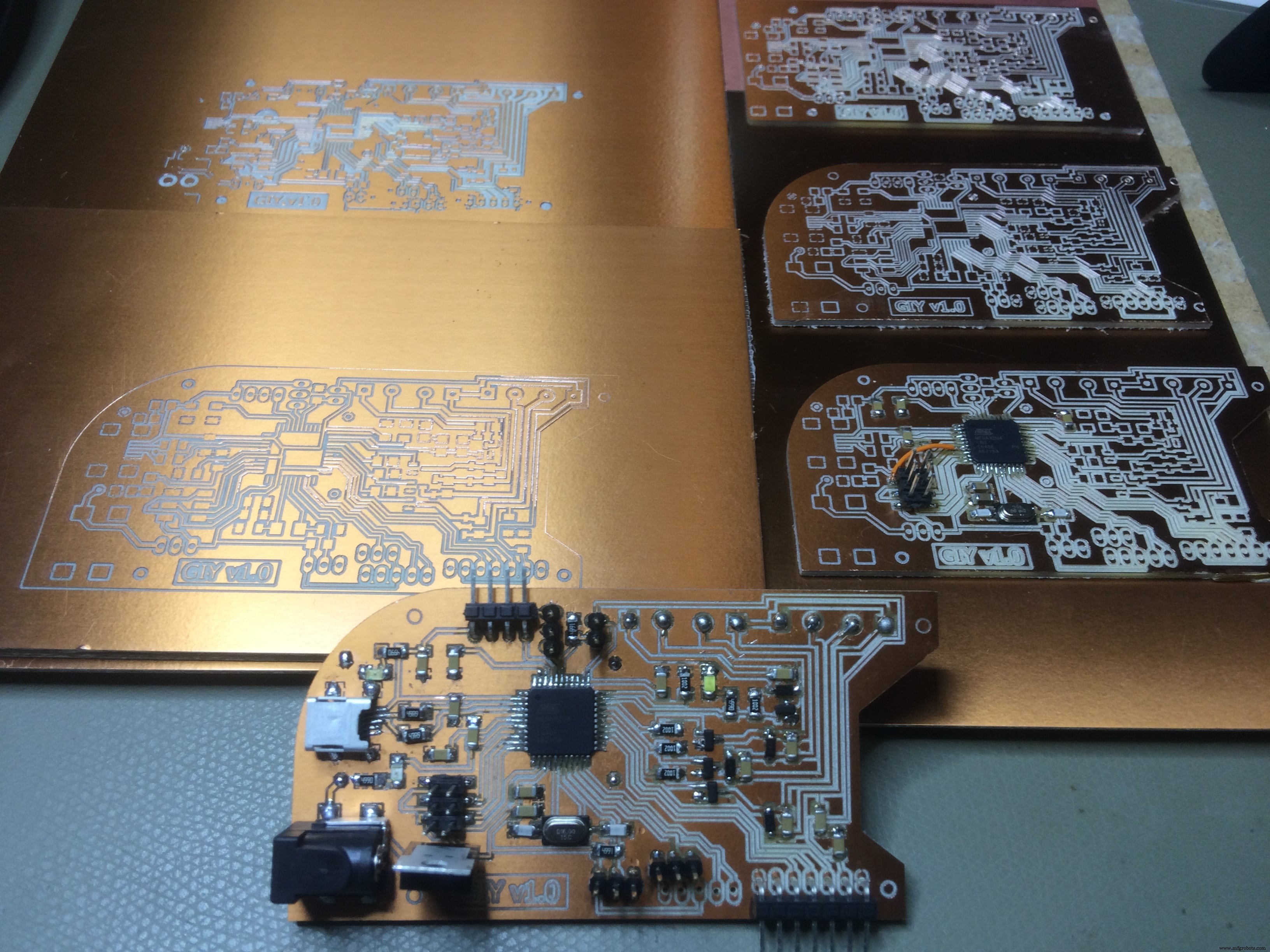
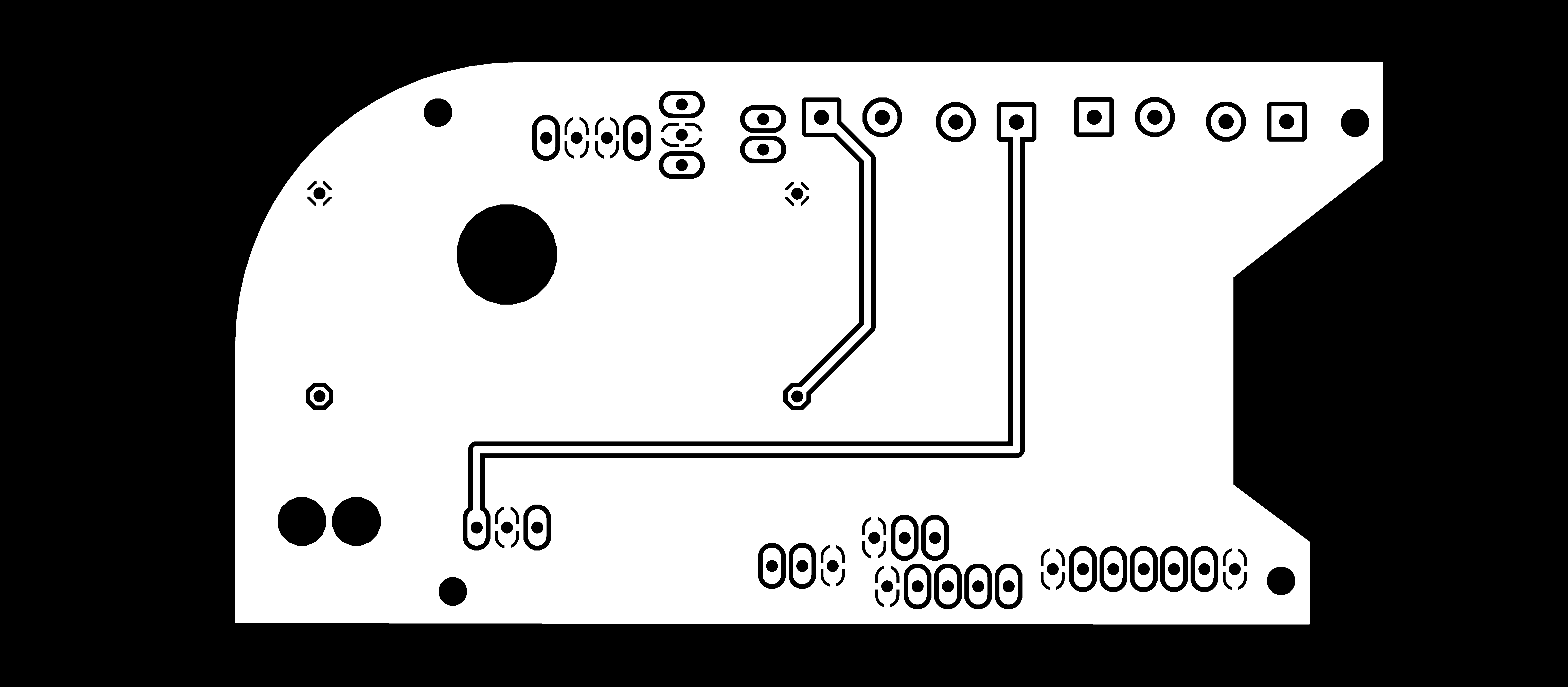
놀랍게도 지금까지 만든 보드 중 가장 복잡한 보드의 라우팅도 가장 빨랐습니다!) 스스로가 자랑스럽습니다. 보드 제작 경험이 속도 향상에 좋은 영향을 미쳤다. 라우팅을 완료한 후의 작은 짐승은 다음과 같습니다.
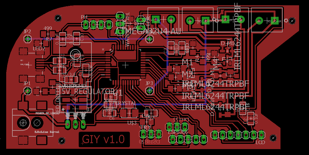
이 보드에서는 이전에 배운 트릭도 사용하고 있습니다. 구성요소 주위에 다각형을 그리고 오른쪽 클릭을 눌러 폴리곤 라인에서 이름을 GND로 변경합니다. 이렇게 하면 다각형 내부의 전체 영역이 채워지고 GND가 됩니다.
이렇게 하면 많은 시간, 공간 및 노력을 절약할 수 있습니다.
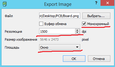
모든 항목을 다시 확인하면 내보내기할 수 있습니다. 내 파일을 .png로 그림.
나타나는 창에서 해상도를 1500dpi로 높입니다. , 흑백을 클릭하십시오. , 창 선택 모드.
.png 이미지를 편집하려면 GIMP에서 이미지를 엽니다. , 직사각형 선택 도구 사용 , 나는 사방에서 약간의 여백을 남기고 이미지를 선택합니다. 파일을 누른 후 및 복사 선택한 지역. 선택한 사진으로 계속 작업하려면 파일을 다시 클릭합니다. , 및 클립보드에서 만들기
이것은 모든 편집 후에 얻은 것입니다:
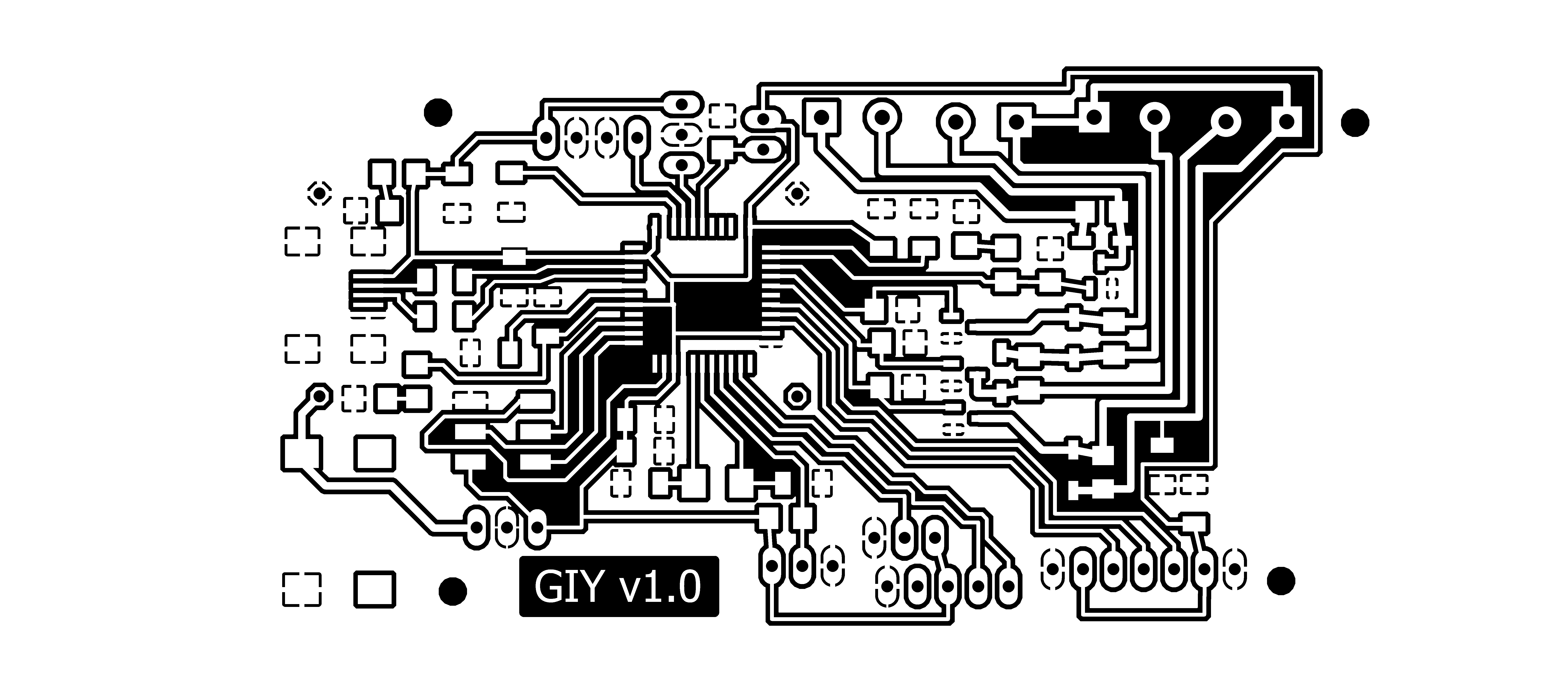
이 이미지는 인쇄할 준비가 되었으며 이름은 Inside_Cut입니다.
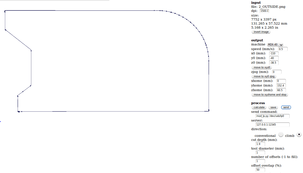
외부 컷을 위한 과정을 준비합니다. , 그리고 이것이 내가 얻은 것입니다:

내 보드는 양면이기 때문에 두 조각을 밀링한 다음 함께 접착해야 합니다. 명심해야 할 것은 하단 부분이 수평으로 미러링되어야 한다는 것입니다.
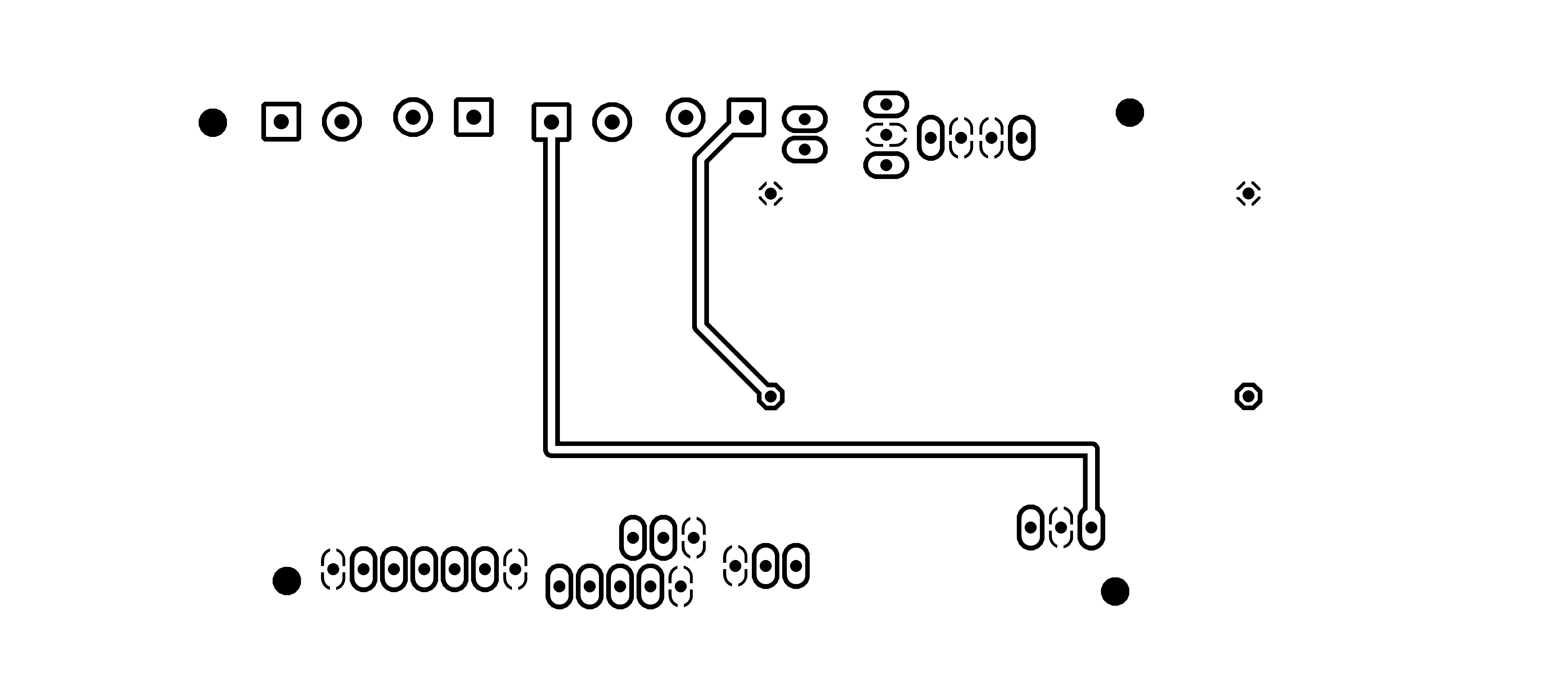
하단 부분 Inside_Cut

하단 부분 Outside_Cut
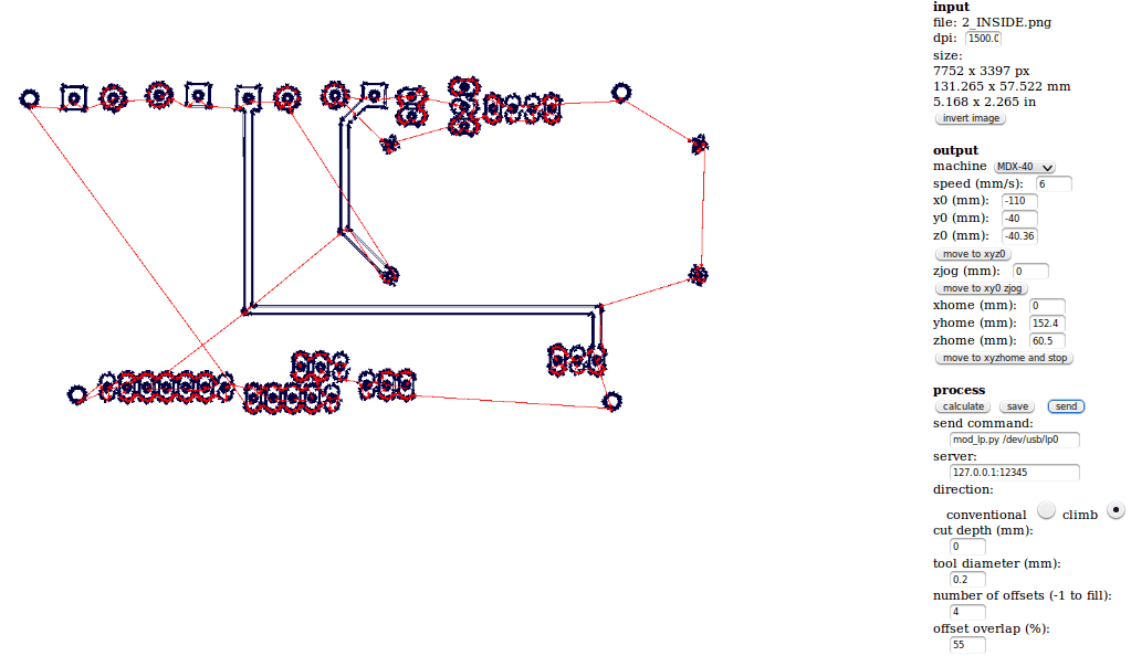
이제 CNC 밀링 머신으로 진행할 수 있습니다. 그래서 다시 FabModules를 사용했습니다. .PNG 파일을 Gcode로 변환 롤랜드 머신용.
Fab 모듈 작업을 시작하겠습니다. 브라우저 창에 IP 주소를 입력하면 첫 번째로 나타나는 인터페이스는 다음과 같습니다.

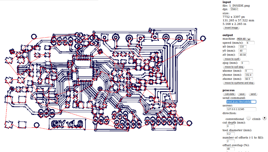
회색 버튼 입력 형식을 누른 후 , 새 메뉴가 .PNG 이미지를 로드하는 옵션과 함께 나타나야 합니다. 여기에 내부 조각인 첫 번째 이미지를 업로드합니다. 그렇게 하면 이미지 미리보기가 Fab 모듈에 나타나고 다른 필드 및 기타 매개변수도 표시됩니다.
창의 오른쪽에는 많은 입력 매개변수가 있습니다. 기계를 이동하려면 다음 매개변수를 입력해야 합니다.
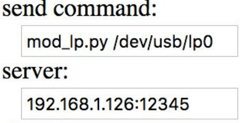
mod_lp.py /dev/usb/lp0 보내기 명령으로 필드
호스트 이름_of_your_machine 서버로 필드(http 또는 /가 없는 주소만)
기계를 이동하기 위해 각 필드에 x, y 및 z 위치 좌표를 입력하기만 하면 됩니다. 기계를 이동하기 전에 zjog 매개변수는 자동으로 변경되더라도 항상 0으로 설정됩니다. 기계를 이동하려면 move to xyz0을 눌러야 합니다. 버튼.
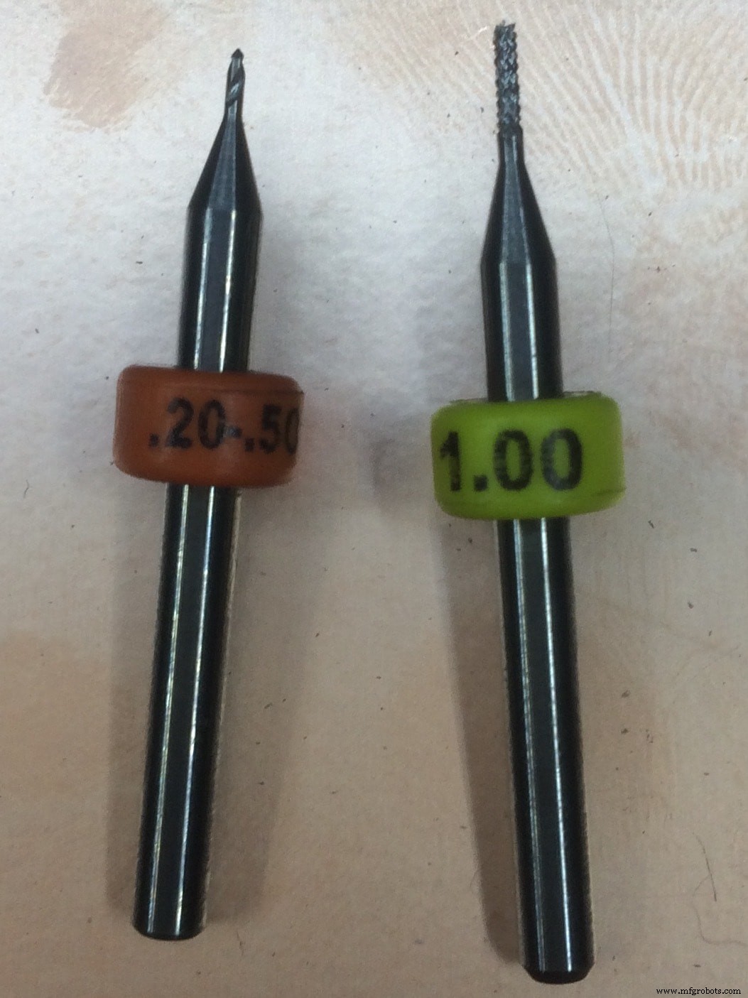
* 작은 생활 핵 멀티미터를 사용하여 공구와 표면이 연결되어 있는지 확인하는 것입니다. PCB 조각 도구로 0.2mm 직경을 사용하는 것이 좋습니다. 아래에서 절단을 위해 1mm를 사용할 수 있습니다. 도구.
최종 설정은 다음과 같습니다.
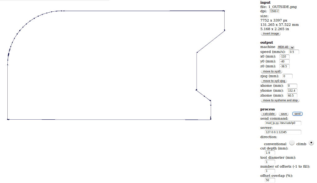
외부 컷의 경우 0.2mm 도구를 1mm 도구로 교체했기 때문에 Z축 값을 제외하고 설정이 동일하게 유지됩니다. 이렇게 생겼습니다:
하단 부분에 대해 동일한 과정을 반복합니다. 내부 및 외부 부품 밀링:
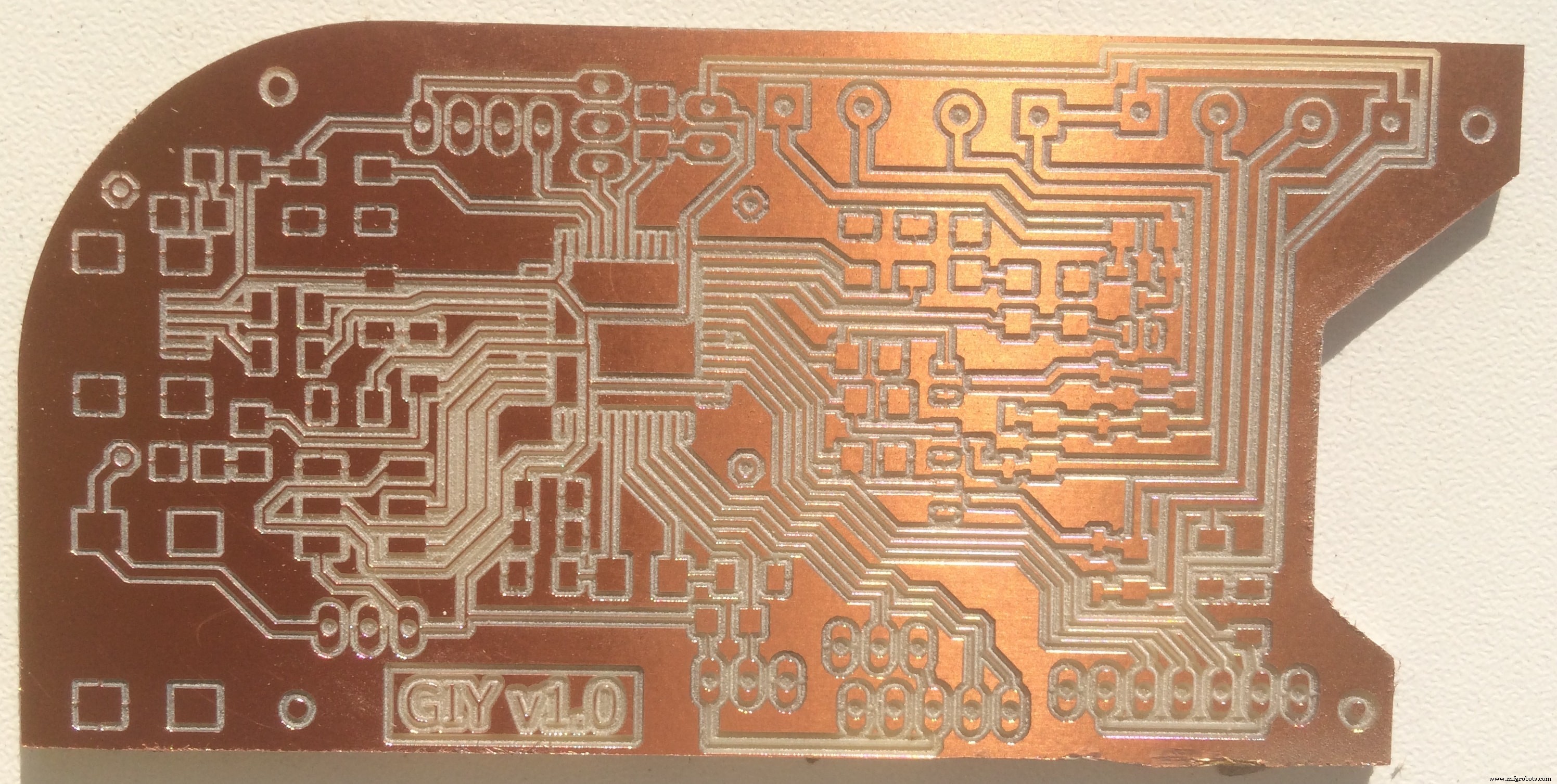
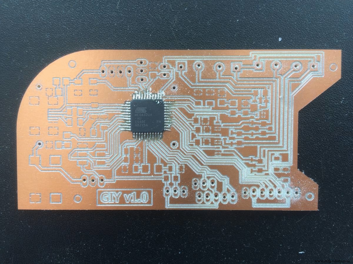
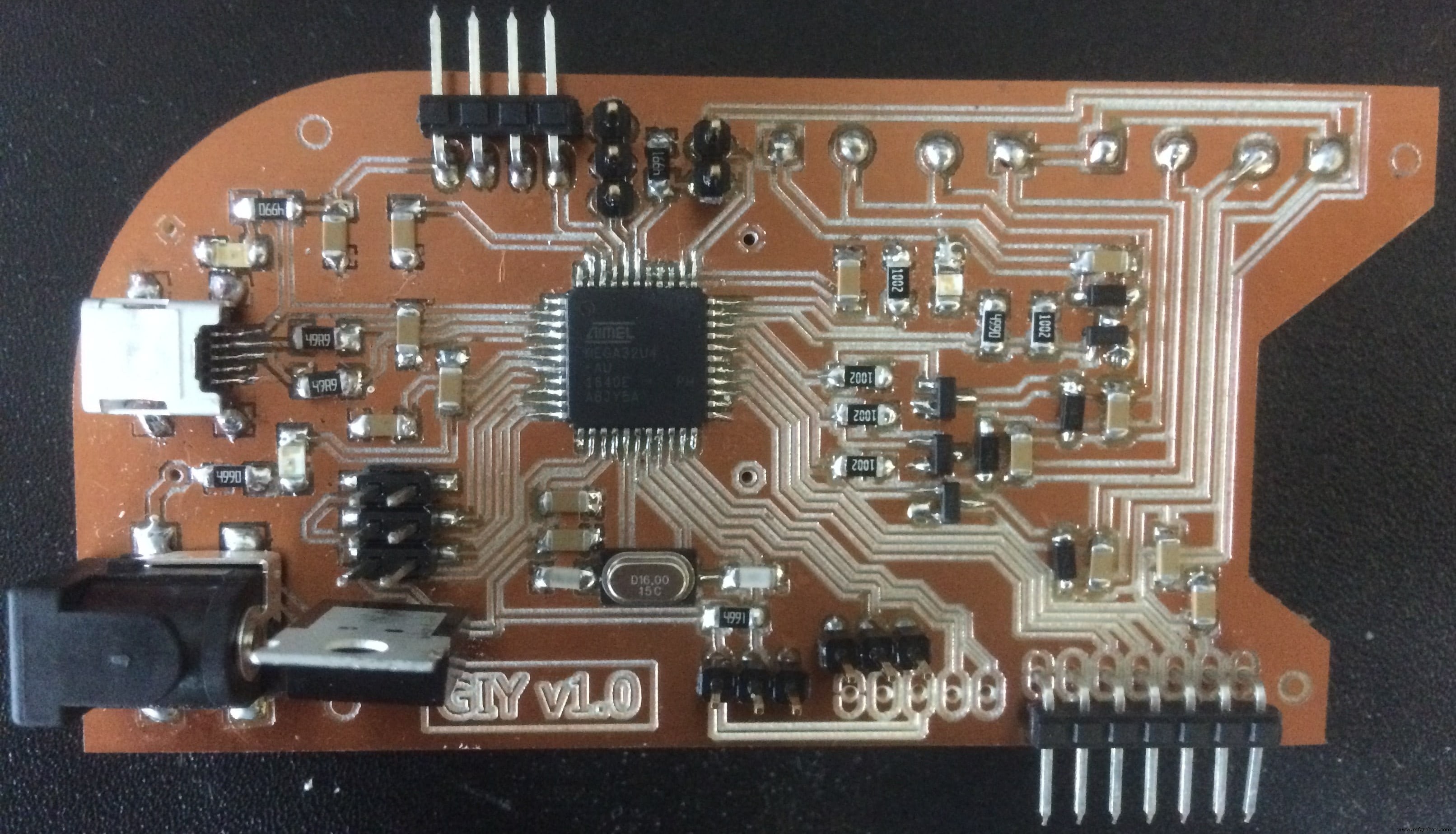
상위에 대한 최종 결과입니다. 부분:
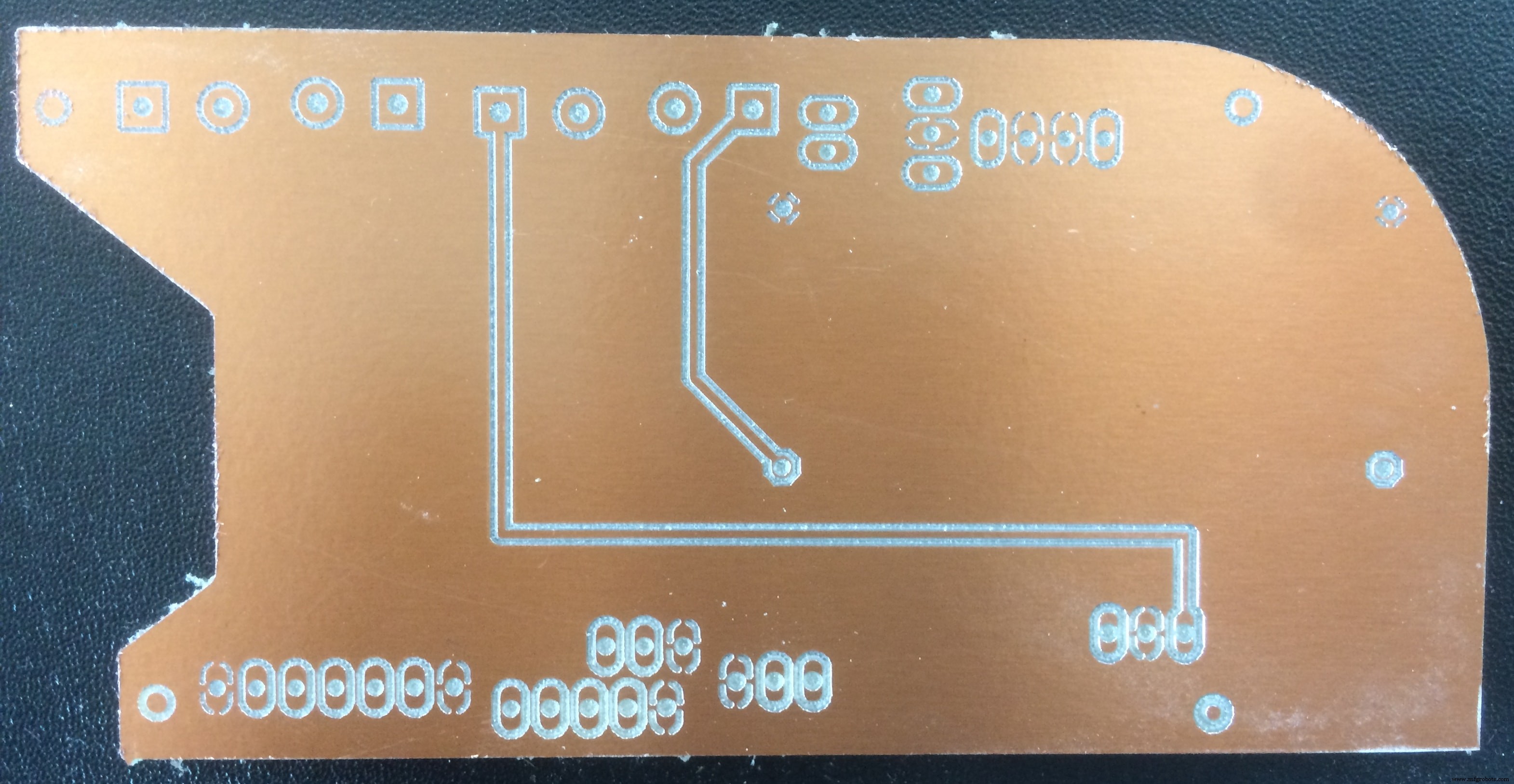
그리고 하단 부분:
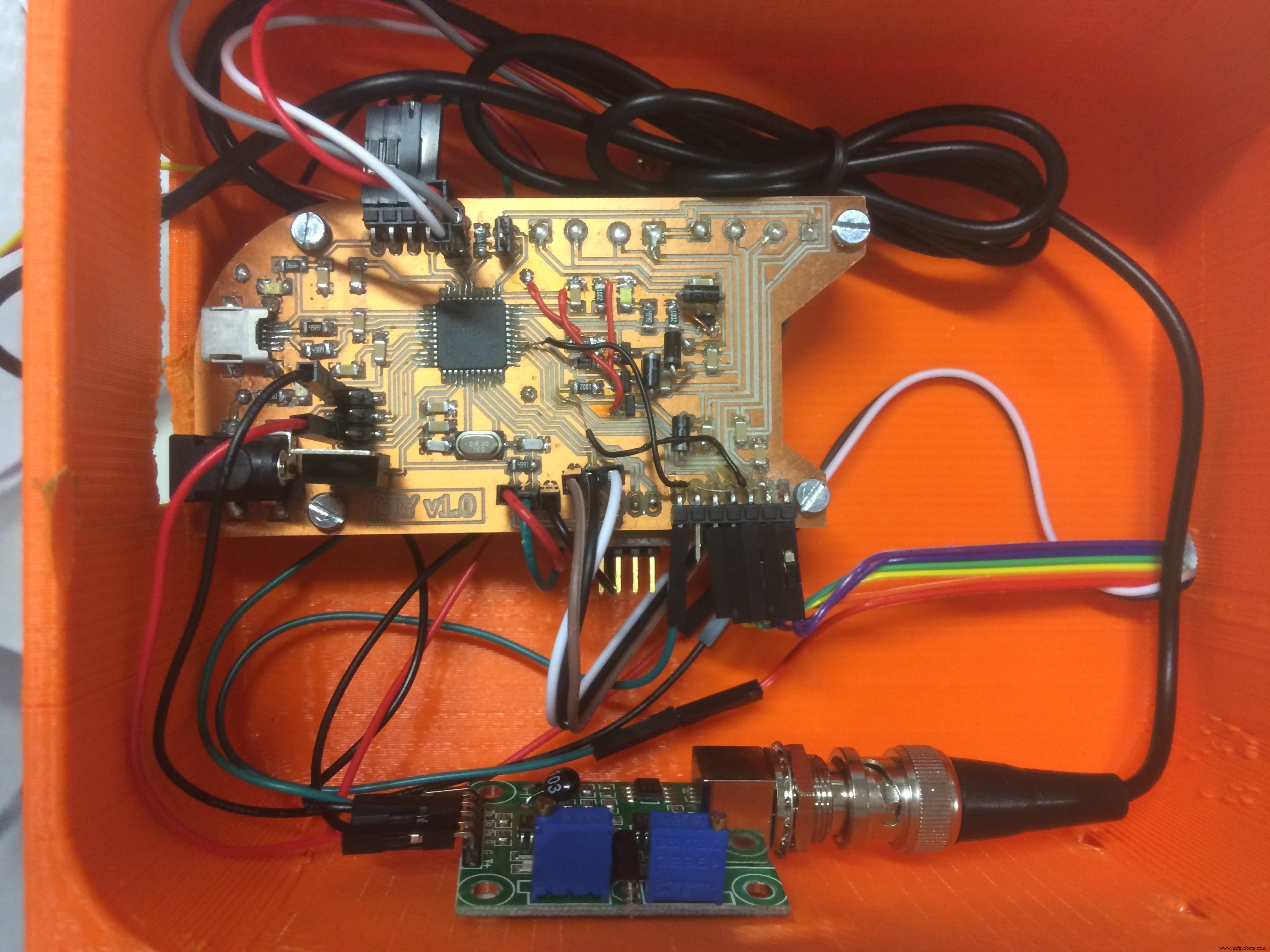
이제 이것을 납땜해 봅시다!
모든 것을 올바른 방법으로 납땜했는지 확인하기 위해 각 구성요소를 납땜한 후 멀티미터를 사용했습니다. to check if there is conductivity between the component and the traces.
Short animation of the process:
When I plugged in the PCB board to check if everything is fine, I noticed an error. From experience, I know that the error was from a short circuit, because the computer was disconecting the Arduino all the time I connect the VCC and GND to it. So my guess was that somewhere on the board VCC and GND are connected, and using the multimeter, I confirmed that I was right.
It was late, and I got so f*ckin' mad because of that, took me one hour under the microscope to find that little mistake. Here it is:
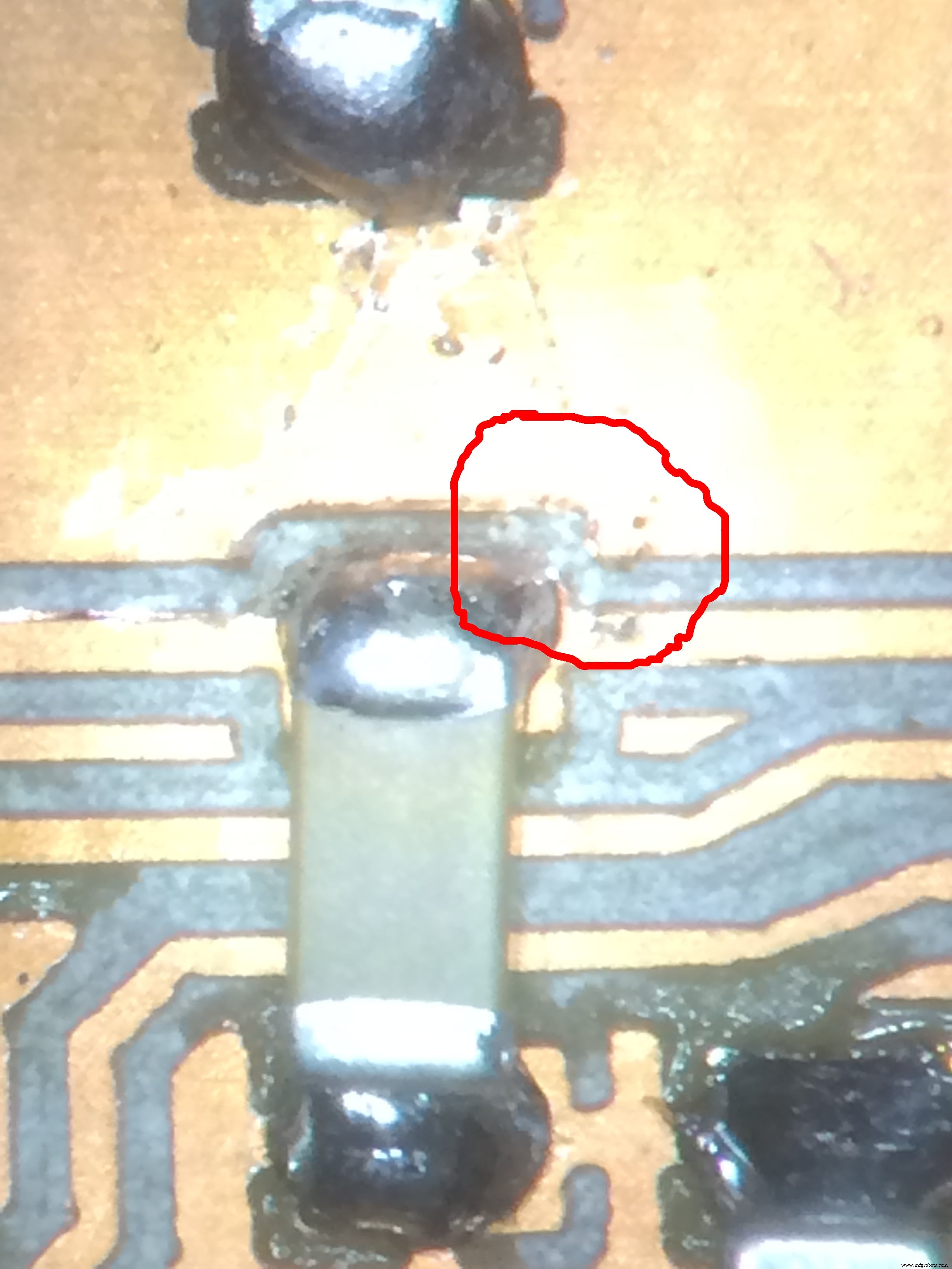
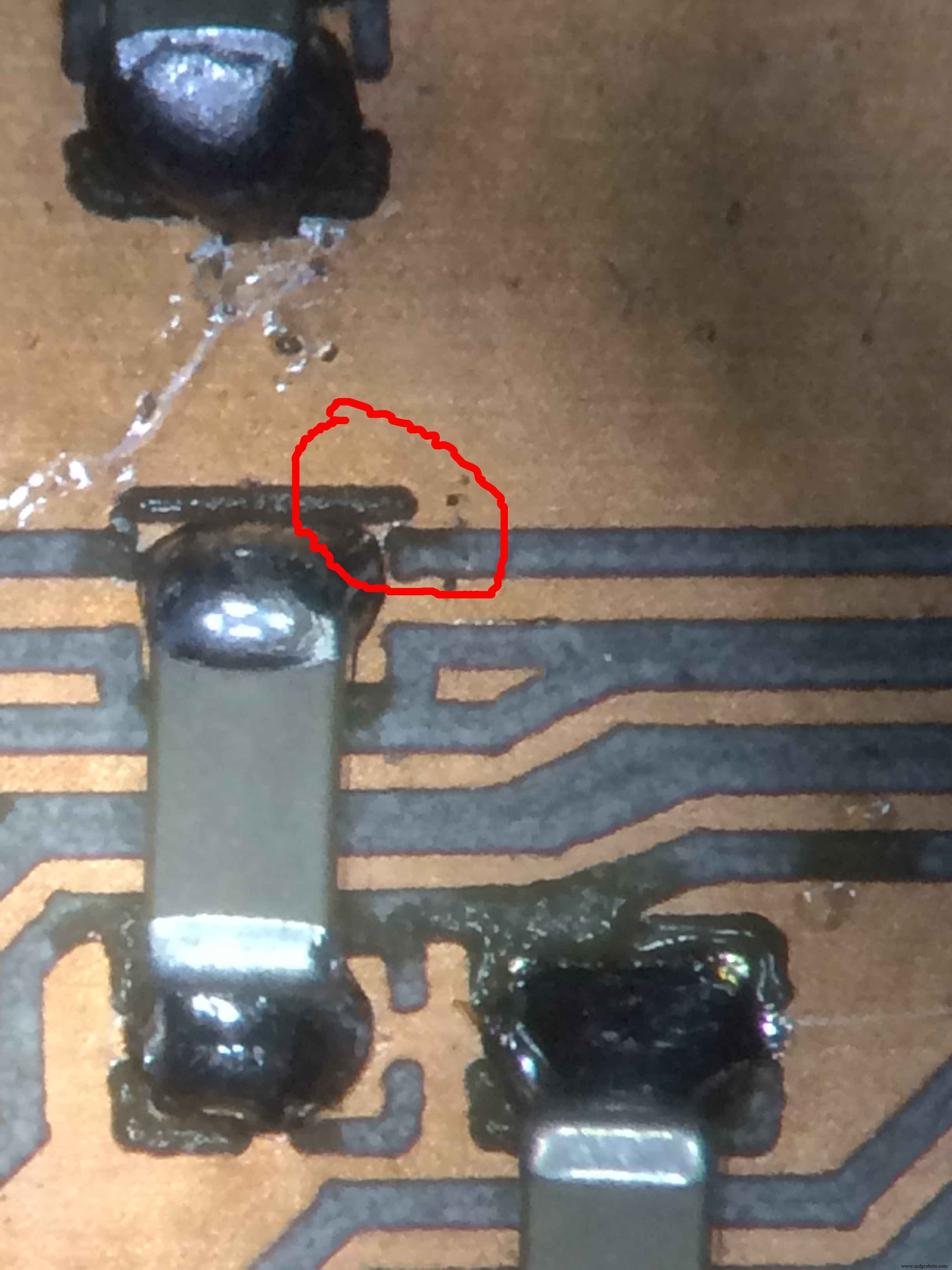
I fixed it by scratching with a knife, and increasing the isolation!
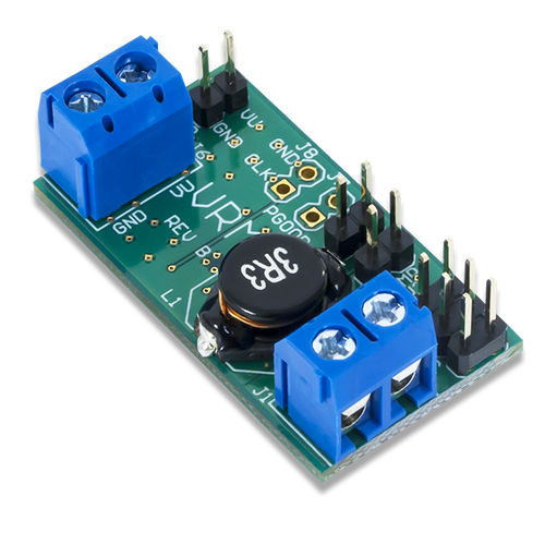
Another thing is placing the Step Up Voltage Reguator on the back side of my board.
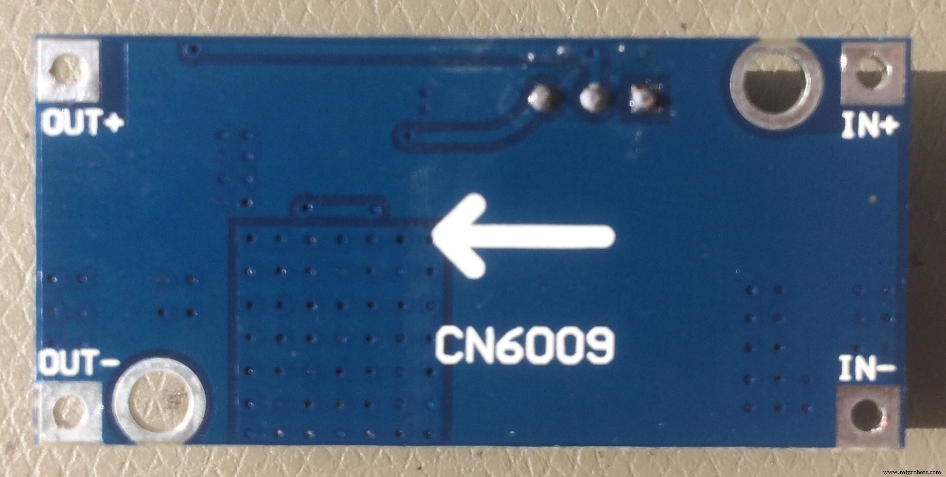
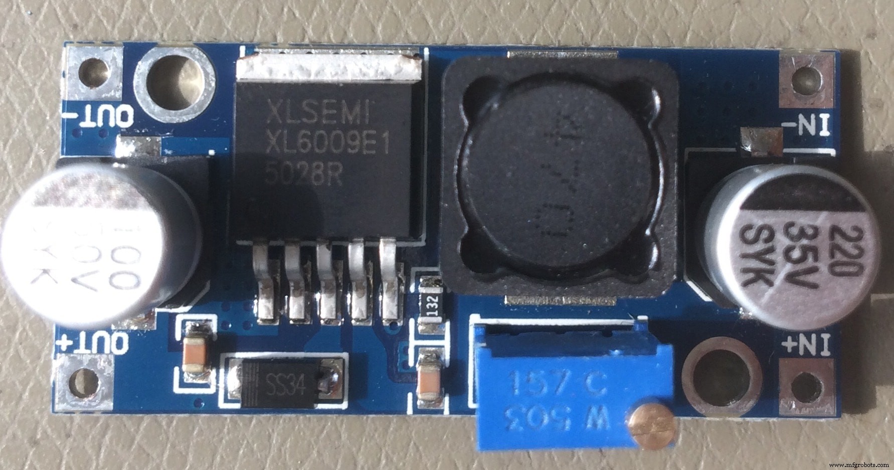
I measured the dimensions in advance, and designed predrilled holes to fix it with the pinheaders. But before soldering it on the back side, I have to calibrate it.
The idea is that when I power the board with 12V, the step up will output 24V necessary for the Ultrasonic Atomizer, which is connected to the MOSFET circuit
I used the bench power supply, with a fixed 12V, to measure the output voltage using a multimeter.
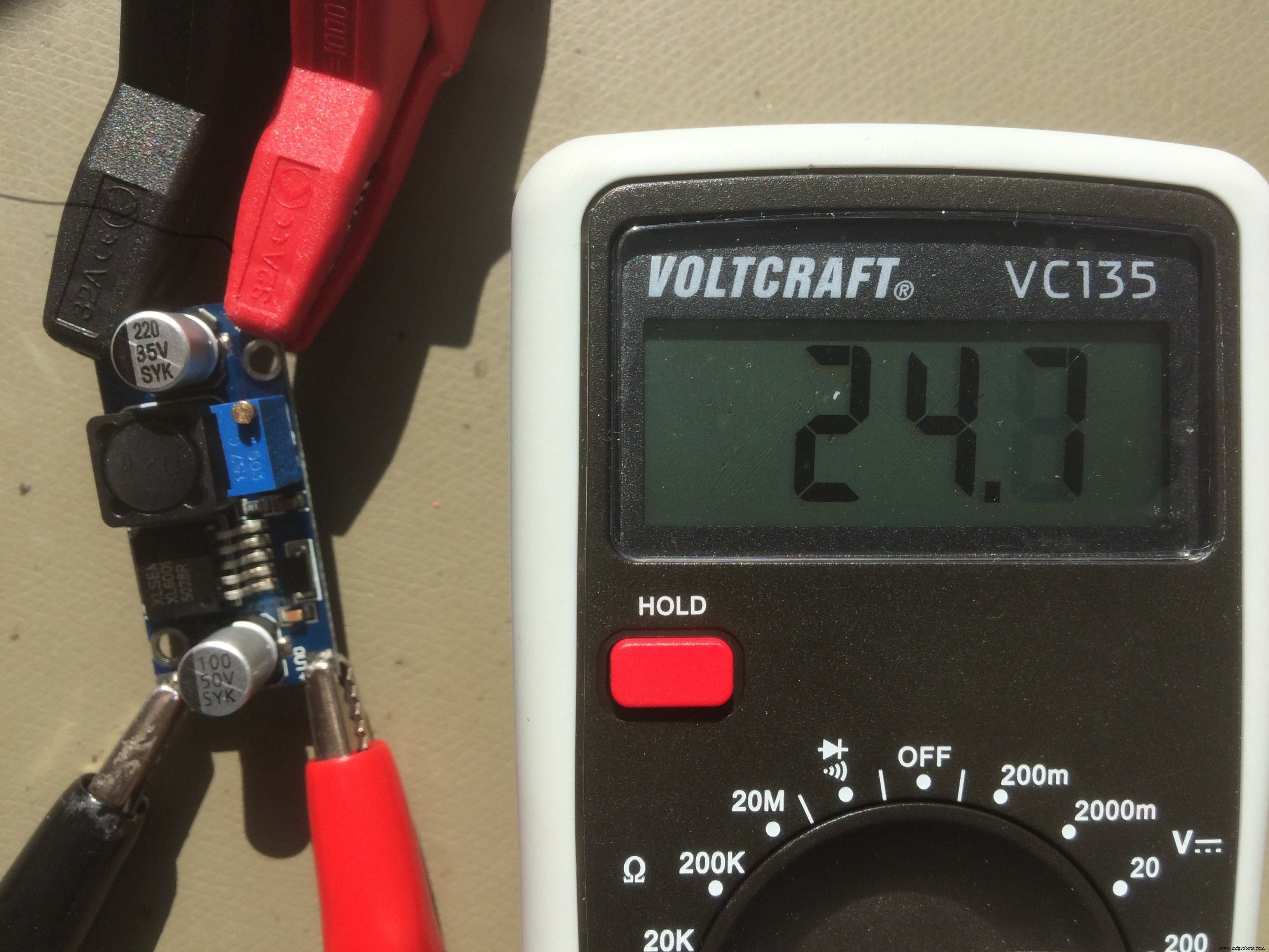
After I adjust the output to the one that I need, 24V in my case, I can solder it to the back side of my board!
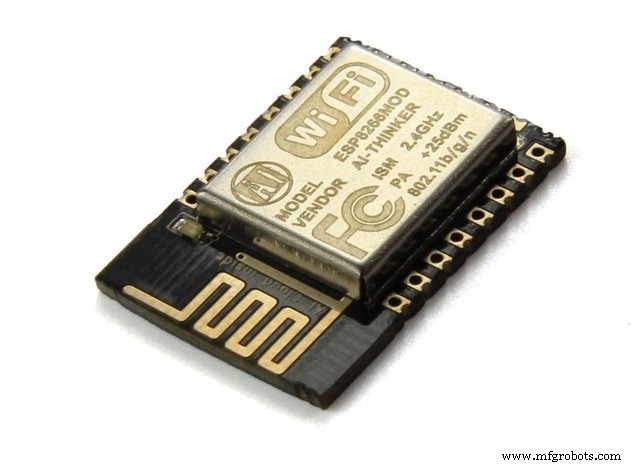
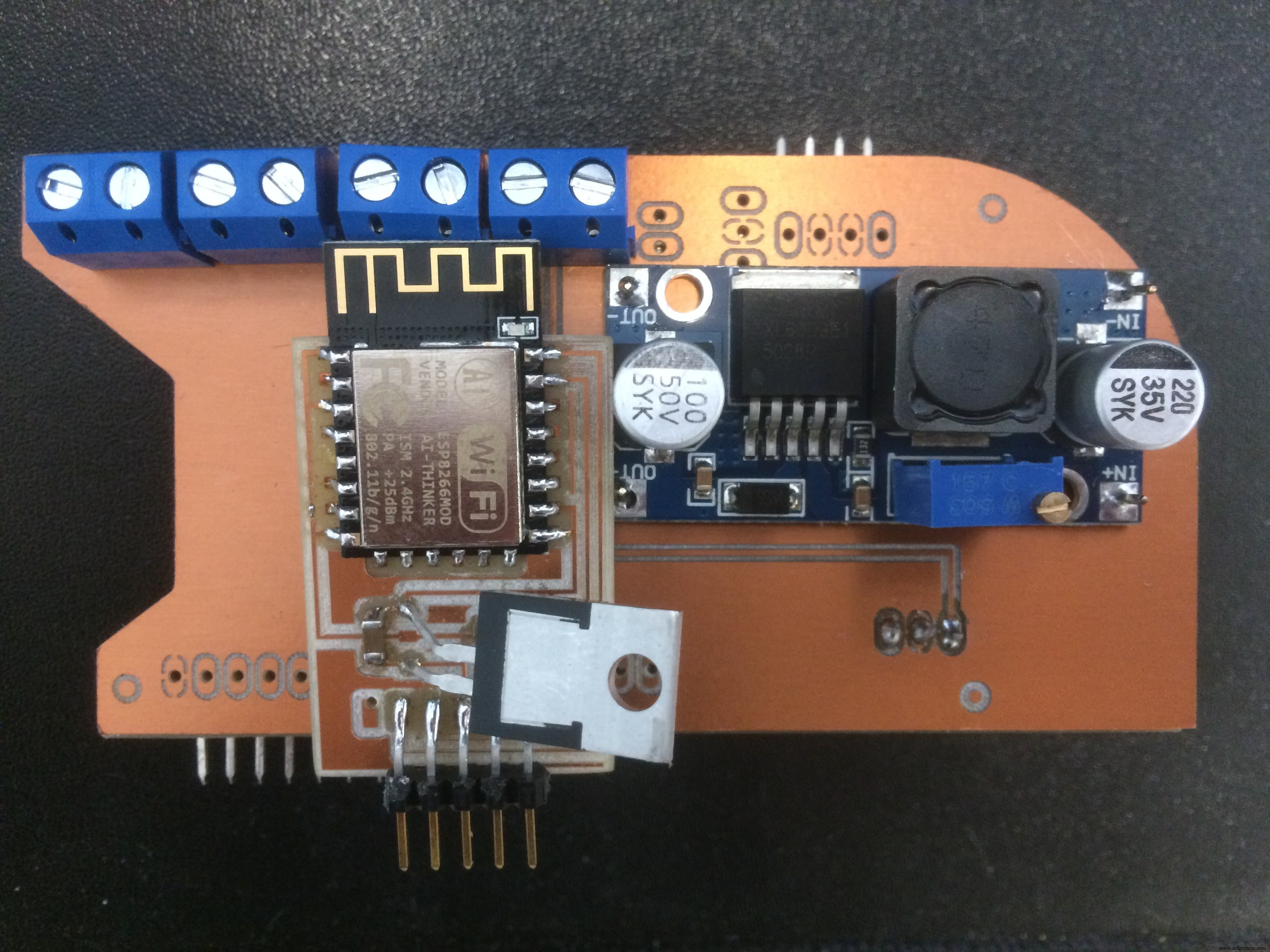
Also on the back side, I placed the WiFi board which I made during the Networking and Communications week!
So, here is The BEAST :
A HERO picture for those who may think that it was easy, and everything went smooth :D
Download Files:
GIY Schematics (.sch)
GIY Layout (.brd)
Board#1 Internal Cut(.png)
Board#1 External Cut (.png)
Board#2 Internal Cut (.png)
Board#2 External Cut (.png)
Wiring &Embedded programming (I/O Devices)
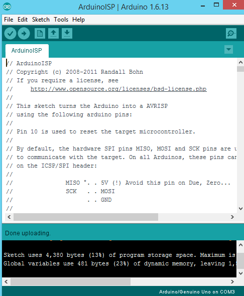
To program my board I used Arduino IDE . I connect the arduino board to the USB hub, in the tools menu select the right board (Arduino Leonardo) and the port, after go to File --> examples and open the Arduino as ISP sketch. 코드를 업로드하세요.
After I see done uploading, which means that the code is uploaded to the board, I disconnect the arduino from the PC. The next step is to connect my PCB board to Arduino using some wires. The connection scheme is this one:
<울>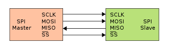
I connect the arduino board to the USB hub. Under Tools select the right board, select Arduino as ISP programmer, double check the parameters, and press the Burn Bootloader button.
And I see Done Uploading! Good sign)
To test the board, I upload the basic Blink example code:
Ohh, I LOVE that BLINK :D Now let's go to sensors!
First sensor that I want to use is DHT11 - Temperature &Humidity Sensor
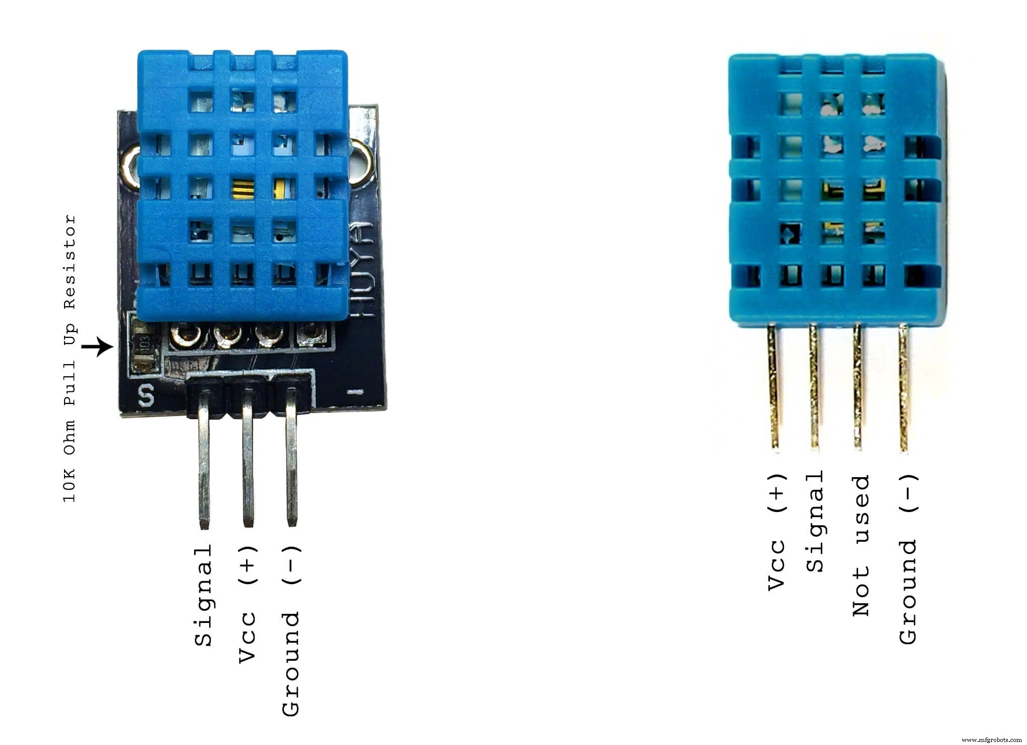
These sensors are very basic and slow, but are great for hobbyists who want to do some basic data logging. The DHT sensors are made of two parts, a capacitive humidity sensor and a thermistor. There is also a very basic chip inside that does some analog to digital conversion and spits out a digital signal with the temperature and humidity. The digital signal is fairly easy to read using any microcontroller.
Some characteristics:
<울>The wiring is pretty easy, just VCC, GND, and any Digital Pin! In my case, I designed in advance the connection for this sensor.
To test it, I will upload a simple sketch. The sketch includes the library DHT.h
So here is the code:
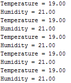
// DHT11 Temperature and Humidity Sensors Example#include "DHT.h" //include DHT library#define DHTPIN 2 //define as DHTPIN the Pin 2 used to connect the Sensor#define DHTTYPE DHT11 //define the sensor used(DHT11)DHT dht(DHTPIN, DHTTYPE); //create an instance of DHTvoid setup() { Serial.begin(9600); //initialize the Serial communication dht.begin(); //initialize the Serial communication}void loop() { float h =dht.readHumidity(); // reading Humidity float t =dht.readTemperature(); // read Temperature as Celsius (the default) Serial.print("Temperature ="); Serial.println(t, 2); //print the temperature Serial.print("Humidity =");; Serial.println(h, 2); //print the humidity delay(2000); //wait 2 seconds } When I open the Serial Monitor, this is what I get:
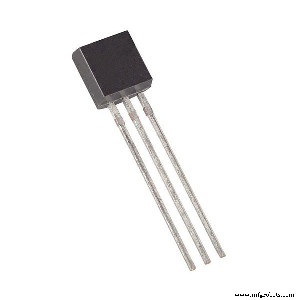
Another sensor which I want to use is DS18B20 - One Wire Digital Temperature Sensor
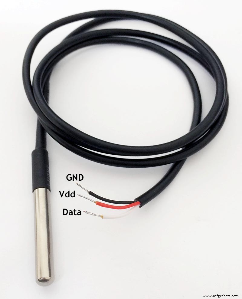
DS18B20 is 1-Wire digital temperature sensor from Maxim IC. Reports degrees in Celsius with 9 to 12-bit precision, from -55 to 125 (+/-0.5). Each sensor has a unique 64-Bit Serial number etched into it - allows for a huge number of sensors to be used on one data bus.
This is by far one of the most simple digital sensors to hookup. Aside from power and ground, it has a single digital signal pin that I will be connecting to digital pin which I designed in advance. It also requires a 4.7k pull-up resistor between the signal and power pin, which unfortunately I forgot to place on my PCB. That is why, I will solder it manually directly to the sensor cables.
Before I start, I have to download the libraries:OneWire.h and DallasTemperature.h
Upload the following sketch:
// First we include the libraries#include #include #define ONE_WIRE_BUS 3 // Setup a oneWire instance to communicate with any OneWire devices, (not just Maxim/Dallas temperature ICs) OneWire oneWire(ONE_WIRE_BUS); // Pass our oneWire reference to Dallas Temperature. DallasTemperature sensors(&oneWire);void setup(void) { // start serial port Serial.begin(9600); sensors.begin(); } void loop(void) { // call sensors.requestTemperatures() to issue a global temperature (request to all devices on the bus)sensors.requestTemperatures(); // Send the command to get temperature readings Serial.print("Temperature is:"); Serial.print(sensors.getTempCByIndex(0)); //You can have more than one DS18B20 on the same bus. 0 refers to the first IC on the wire delay(1000); } The funny thing is that after I successfully programmed the sensor, It stopped working while I was integrating all the sensors together! I spend quite a long time trying to figure out why it does not work, but due to the limited time, I decided to use another DS18B20 sensor which was available in our FabLab stock, and waterproof it by myself!
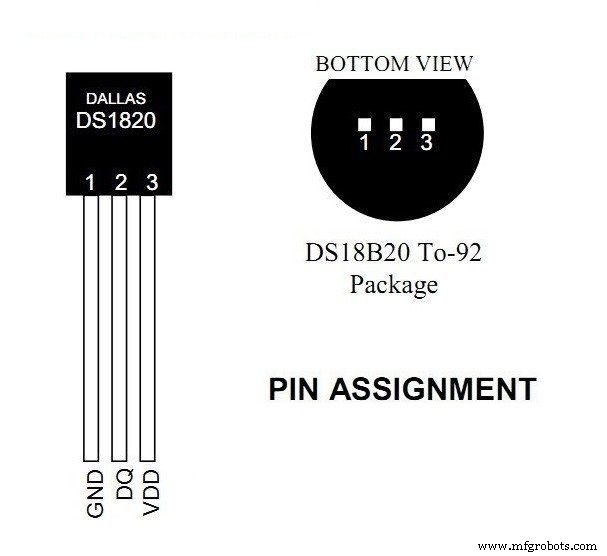
So I took the sensor, and used the datasheet to properly solder the cables, and isolate them from each other using shrink tubes
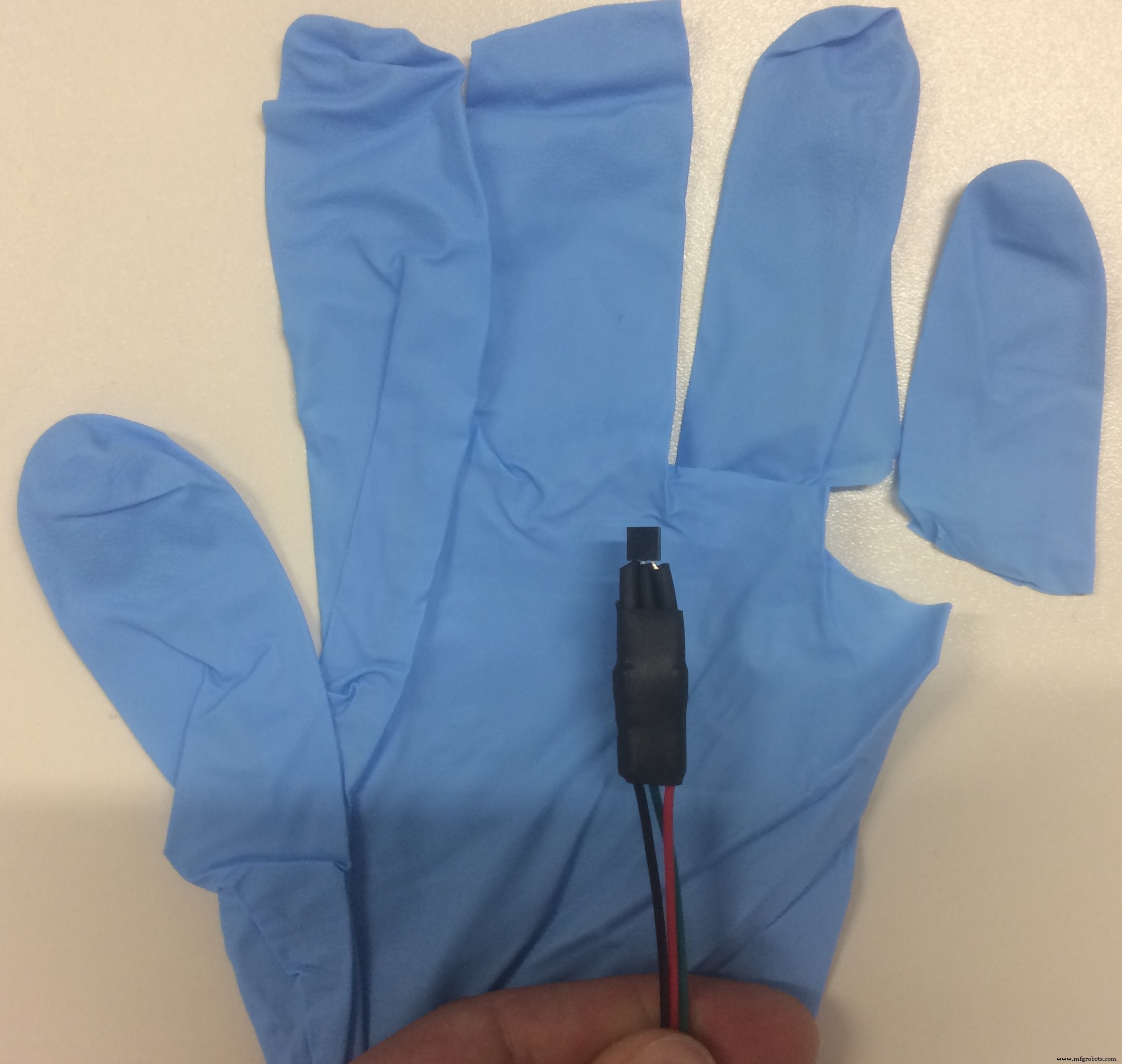
I guess you have got the idea how I am going to waterproof it, right? :D Mama ama engineer!
Said &DONE!
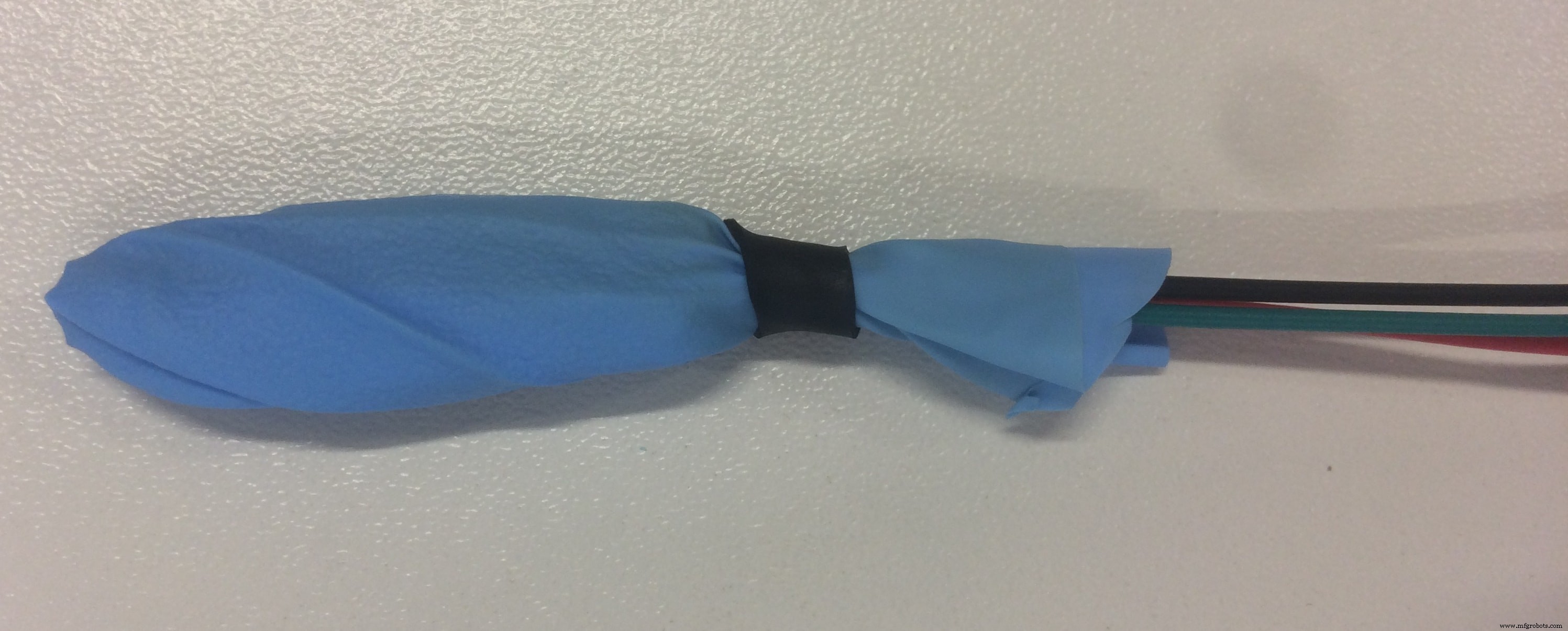
Yeah, I know what it looks like :D but I assure you, its just a hand waterproof sensor. The most important is that it works, and does not leak when submerged in water!
And we go to the next sensor which is LDR =Light Dependent Resistor
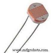
LDR is a passive electronic component, basically a resistor which has a resistance that varies depending of the light intensity. The resistance is very high in darkness, almost high as 1MΩ but when there is light that falls on the LDR, the resistance is falling down to a few KΩ (10-20kΩ @ 10 lux, 2-4kOmega; @ 100 lux) depending on the model.
The LDR gives out an analog voltage when connected to Vcc (5V), which varies in magnitude in direct proportion to the input light intensity on it. That is, the greater the intensity of light, the greater the corresponding voltage from the LDR will be. Since the LDR gives out an analog voltage, it is connected to the analog input pin on the Arduino. The Arduino, with its built-in ADC (Analog to Digital Converter), then converts the analog voltage (from 0-5V) into a digital value in the range of (0-1023). When there is sufficient light in its environment or on its surface, the converted digital values read from the LDR through the Arduino will be in the range of 800-1023.
Here is the sketch code to test the sensor:
int sensorPin =A0; /* select the input pin for LDR */int sensorValue =0; /* variable to store the value coming from the sensor */void setup(void) { Serial.begin(9600); /* start serial port */} void loop(void) { sensorValue =analogRead(sensorPin); // read the value from the sensor // We'll have a few threshholds, qualitatively determined Serial.print("LDR Value ="); Serial.print(sensorValue); if (sensorValue <100) { Serial.println(" (Dark)"); } else if (sensorValue <200) { Serial.println(" (Dim)"); } else if (sensorValue <500) { Serial.println(" (Light)"); } else if (sensorValue <800) { Serial.println(" (Bright)"); } else { Serial.println(" (Very bright)"); } delay(3000);} Next is Water Level Sensor
I want to have a water level sensor in order to receive an alarm when the water container is empty, and its time to add some water. Because I did not think about it in advance, and we did not have any water level sensor in our stock, I decided that I can make my own water sensor!
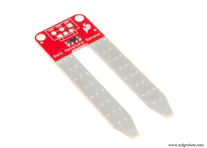
I decided to use the materials available, in my case the Soil Moisture Sensor . The basic principle of the water level sensor is to measure electric conductivity, which is the same for the soil moisture sensor. I thought that If I can calibrate the sensor in a way that will fulfil my requirements, I can use the moisture sensor like an water level sensor) In principle, this is an analog sensor and the data that we will read will be values from 0 to 1024, and the rest is just math!
But as it often happens, the reality is slightly different. When the sensor is not in touch with the water, the analog value is 0, and when I submerge only the tip, the value goes to 800. I used the following sketch to read the values:
/* Print values from analog pin A4 to serial monitor */void setup(){ Serial.begin(9600); }void loop(){ Serial.println(analogRead(A4)); delay(100);} After I can read the values, I calibrated the sensor to give out three different responses:EMPTY! - when the value is 0, LOW when the values are around 800, and Full when the values are more than 900!
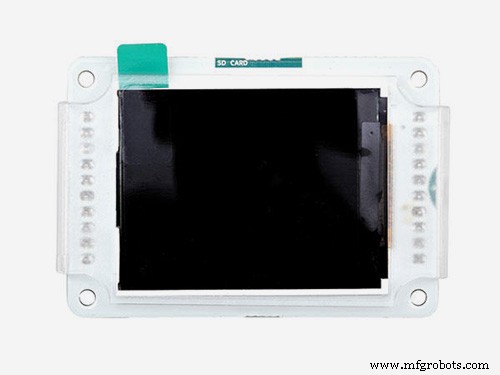
Graphic LCD Display
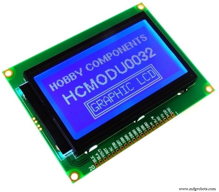
Because usually the LCD displays use a lot of pins, I had to find a way to connect the 128×64 screen in another way, and I DID!!! This way alows using only 3 Digital Pins on the board which is awesome because I may need the rest of the pins for other stuff, and it does not create a mess of wires. I premade the pins for the LCD on my PCB, and this is how I connected everything:
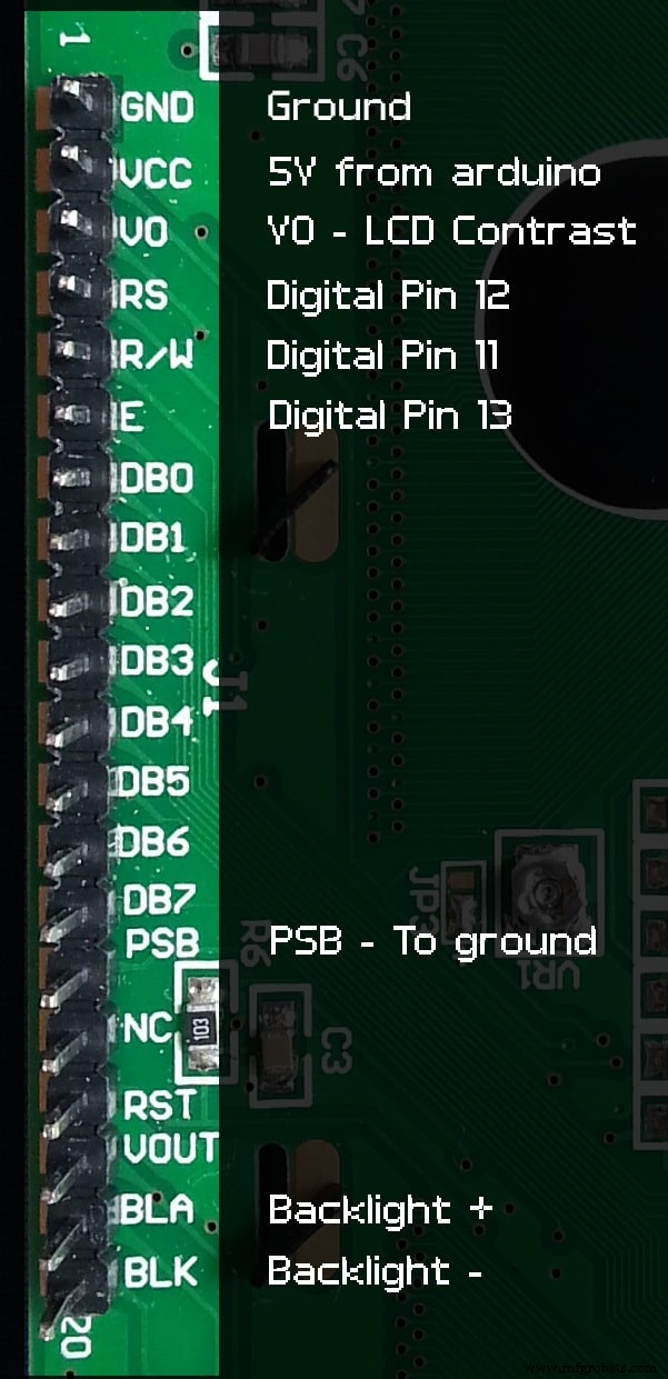
After I connect the LCD, It's time to programm it!
First of all, I have to download the U8glib library from HERE. Another important thing is the declared pins used in the code. The one I used are the following: U8GLIB_ST7920_128X64 u8g(4, 12, 6, U8G_PIN_NONE)
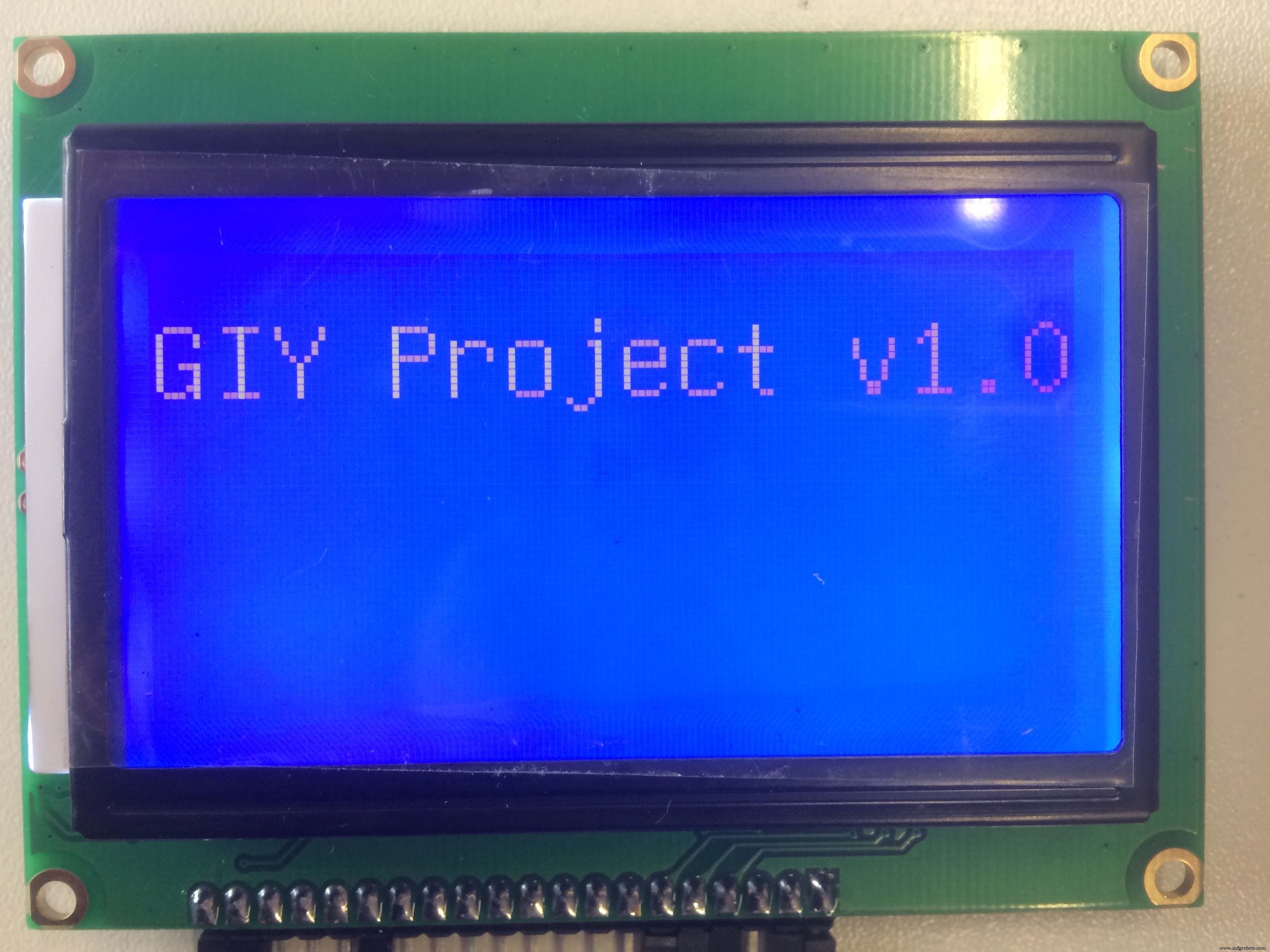
Using the "HELLO WORLD" library example, I came up with this test code:
#include "U8glib.h"U8GLIB_ST7920_128X64 u8g(4, 12, 6, U8G_PIN_NONE);void draw(void) { // graphic commands to redraw the complete screen should be placed here u8g.setFont(u8g_font_unifont); u8g.setPrintPos(0, 20); // call procedure from base class, http://arduino.cc/en/Serial/Print u8g.print("GIY Project v1.0!");}void setup(void) { // flip screen, if required // u8g.setRot180();}void loop(void) { // picture loop u8g.firstPage(); { 무승부(); } 동안( u8g.nextPage() ); // rebuild the picture after some delay delay(500);} And this is what I get:
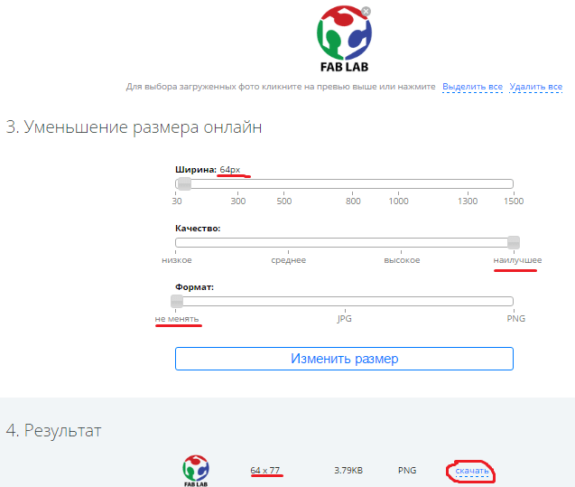
One cool idea that came to my mind was to display the FabLab logo for some seconds, all the time when the display is powered. I spent quite a lot of time on doing this, but I finally did it! In order to display it on the Graphic LCD, I had to have a (.bmp) format picture, and display it as a bitmap.
First thing which I did was download the FabLab logo from the internet as a (.png) file, and reduce it significantly in size, so it fits my small LCD borders. I used the following online service to do that:LINK
These are the configurations I used:
The next step is to convert my small picture into (.bmp) format. I used the following online service to do that:LINK
Now, after I have my (.bmp) file, in order to place it into my code, I have to convert it into HEX 정렬. I used a nice tool called LCD Assistant . To load up an image in LCD Assistant, go to File> Load Image. A preview of the image should open up, make sure it’s the right size – 128 pixels wide, 64 pixels tall . Also make sure the Byte orientation is set to Horizontal and the Size endianness is set to Little . These are the configurations for my LCD Display:
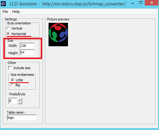
Then I go to File> Save output to generate a temporary text 파일. Open that text file to have a look at my shiny new array.
pH Sensor
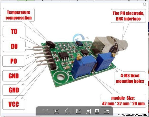
I should admit that this is the most tricky sensor from all that I played with! It is really hard to find any info about the sensor which I am using (logo ph sensor v1.1) , so I decided to make a detailed description about it!
The probe is like a (tiny) battery when placed in a liquid. Depending the pH it output a positive or negative voltage of a couple of millivolts. This value is too small and other tech stuff like impedance make it unusable directly with an Arduino, that's why you need an "op amp". The op amp board just convert the millivolts of the probe into to something acceptable for Arduino (positive between 0 and 5v).
There are 3 common buffer solutions used for pH measurement:pH 4.01, pH 6.86 and pH 9.18 (7.0 and 10.0 exists). I suggest the powder instead the liquid because it's cheaper, expire after longer and the powder can't be contaminated (vs bottle). You should read the product instructions but usually you have to put the content of the bag into 250ml of water and stir. You can use any water with an average pH (6-8) because the powder will saturate the water at the correct pH level. I personally use tap water (pH 7.4) and didn't see any difference between distilled, and demineralized water. Buffers are not stable in the time, this means that you cannot keep the solution for weeks or months.
Now let's talk more about the sensor that I am using!
<울>Now let's try to calibrate the sensor! There are 2 different parameters, the "offset" value and the "step" value
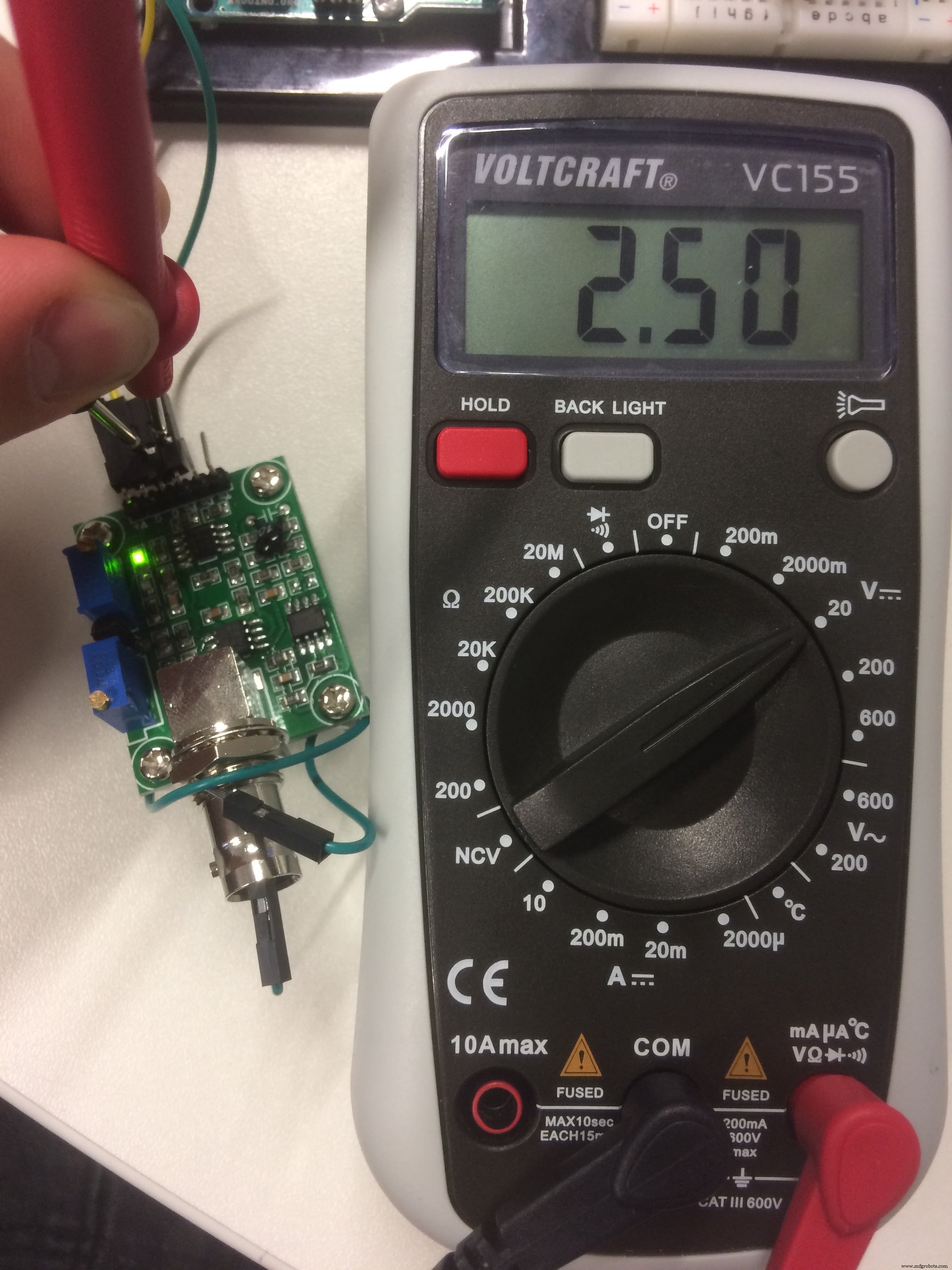
The offset is the shifting of all pH values to a specific voltage range. If a pH 7 output a voltage of 2.2v and pH 8 a voltage of 2.1v, then a shift of +0.3v move the pH 7 to 2.5v and the pH 8 to 2.4v. This can be done on the board or via software but it's probably easier on the board because it's probe independent and there are less programming to do.
Connect GND (both) and Vcc to Arduino GND and 5v. Remove the probe and do a short circuit between the the small BNC hole and the external part of BNC. Put a voltmeter (or Arduino) to measure the voltage between GND and Po. Adjust the pot (close BNC) until the output is 2.5v. Now the pH 7 have an exact value of 2.5v (511 with analogRead function) because the probe will output 0 millivolt.
To calibrate the steps I need one or more buffer solutions depending on the range and precision required. Ideally it is better to know the range of the measure with the system. I use water between pH 5 and pH 7, then I choose the buffer 4.01 (and 6.86 to verify my stuff). If you usually measure pH between 8 and 10 choose buffer 9.18 (eventually 6.86 also).
I connect the (clean) probe and put it in the buffer, then let it stabilize for a minute. I know it's stable when it goes up and down (3.04 then 3.05 then 3.03 then 3.04).Take note of the voltmeter (or Arduino) value, in my example it's 3.05v.
That's all, now I can use it with the code below.
int ph_pin =A7; //This is the pin number connected to Povoid setup() { Serial.begin(9600);}void loop() { int measure =analogRead(ph_pin); Serial.print("Measure:"); Serial.print(measure); double voltage =5 / 1024.0 * measure; //classic digital to voltage conversion Serial.print("\tVoltage:"); Serial.print(voltage, 3); // PH_step =(voltage@PH7 - voltage@PH4) / (PH7 - PH4) // PH_probe =PH7 - ((voltage@PH7 - voltage@probe) / PH_step) float Po =7 + ((2.5 - voltage) / 0.18); Serial.print("\tPH:"); Serial.print(Po, 3); Serial.println(""); 지연(2000);} The PH_step calculation is quite simple. I take the difference between the two known voltage, in my example 2.5v@pH7 and [email protected] which is -0.55v. It's the voltage range equivalent of the pH range from 7 to 4.01, which is 2.99 pH units. A small division of the voltage by pH units gives a volts per pH number (0, 1839... in my case).
The PH_probe is calculated by taking the known pH 7 voltage (2.5v) where we add some PH_step to match the probe voltage. This means that a pH of 8 has a voltage value of 2.5v (pH 7) + 0.1839 (1 unit/step); pH 9 then is 2.5v + 0.1839 + 0.1839 =2.87v.
No magic, JUST MATH :D
MOSFET output:
I connected the RGB LED stripe and the Ultrasonic Atomizer to the MOSFET circuit outputs, which are controlled by digital pins. For the LED lights, I stated in the setup digitalWrite (LED, HIGH); , which means that the LED will switch on all the time when the system is powered. For the Fog maker, I made an If function depending on the water level value. If there is water, the fog maker is ON, if there is no water, EMPTY!, then the fog is OFF!
Now Let's put things together!
Here I came up with my final code:
#include "dht.h"#include "U8glib.h"#include #include #define DHT11_PIN 2 // what digital pin we're connected to#define ONE_WIRE_BUS 3#define WATER_LEVEL A4#define LDR_PIN A3#define PH_PIN A5#define GROW_LIGHT 10#define FOG_PUMP 13int waterLevel;int LightLevel;int pH;dht DHT;OneWire oneWire(ONE_WIRE_BUS); DallasTemperature waterTemp(&oneWire);U8GLIB_ST7920_128X64 u8g(4, 12, 6, U8G_PIN_NONE);const unsigned char logo [] PROGMEM ={0xFF, 0xFF, 0xFF, 0xFE, 0x7F, 0xFF, 0xFF, 0xFF, 0x00, 0x00, 0x00, 0x00, 0x00, 0x00, 0x00, 0x00,0xFF, 0xFF, 0xFF, 0x00, 0x00, 0xFF, 0xFF, 0xFF, 0x00, 0x00, 0x00, 0x00, 0x00, 0x00, 0x00, 0x00,0xFF, 0xFF, 0xF8, 0x00, 0x00, 0x1F, 0xFF, 0xFF, 0x00, 0x00, 0x00, 0x00, 0x00, 0x00, 0x00, 0x00,0xFF, 0xFF, 0xC0, 0x00, 0x00, 0x03, 0xFF, 0xFF, 0x00, 0x00, 0x00, 0x00, 0x00, 0x00, 0x00, 0x00,0xFF, 0xFF, 0x00, 0x00, 0x00, 0x00, 0xFF, 0xFF, 0x00, 0x00, 0x00, 0x00, 0x00, 0x00, 0x00, 0x00,0xFF, 0xFE, 0x00, 0x03, 0xC0, 0x00, 0x7F, 0xFF, 0x00, 0x00, 0x00, 0x00, 0x00, 0x00, 0x00, 0x00,0xFF, 0xF8, 0x00, 0x07, 0xE0, 0x00, 0x3F, 0xFF, 0x00, 0x00, 0x00, 0x00, 0x00, 0x00, 0x00, 0x00,0xFF, 0xF0, 0x00, 0x1F, 0xF8, 0x00, 0x0F, 0xFF, 0x00, 0x00, 0x00, 0x00, 0x00, 0x00, 0x00, 0x00,0xFF, 0xE0, 0x00, 0x3F, 0xFE, 0x00, 0x07, 0xFF, 0x00, 0x00, 0x00, 0x00, 0x00, 0x00, 0x00, 0x00,0xFF, 0xC0, 0x00, 0 x18, 0x1F, 0x00, 0x03, 0xFF, 0x00, 0x00, 0x00, 0x00, 0x00, 0x00, 0x00, 0x00,0xFF, 0x80, 0x00, 0x00, 0x03, 0xC0, 0x01, 0xFF, 0x00, 0x00, 0x00, 0x00, 0x00, 0x00, 0x00, 0x00,0xFF, 0x00, 0x00, 0x00, 0x00, 0xF0, 0x00, 0xFF, 0x00, 0x00, 0x00, 0x00, 0x00, 0x00, 0x00, 0x00,0xFE, 0x00, 0x00, 0x00, 0x00, 0x7C, 0x00, 0x7F, 0x00, 0x00, 0x00, 0x00, 0x00, 0x00, 0x00, 0x00,0xFC, 0x00, 0x00, 0x00, 0x00, 0x3E, 0x00, 0x7F, 0x00, 0x00, 0x00, 0x00, 0x00, 0x00, 0x00, 0x00,0xFC, 0x03, 0x80, 0x00, 0x00, 0x3F, 0x80, 0x3F, 0x00, 0x00, 0x00, 0x00, 0x00, 0x00, 0x00, 0x00,0xF8, 0x07, 0xE0, 0x00, 0x00, 0x1F, 0xE0, 0x1F, 0x00, 0x00, 0x00, 0x00, 0x00, 0x00, 0x00, 0x00,0xFC, 0x1F, 0xF0, 0x00, 0x00, 0x1F, 0xF0, 0x1F, 0x00, 0x00, 0x00, 0x00, 0x00, 0x00, 0x00, 0x00,0xF0, 0x3F, 0xF0, 0x00, 0x00, 0x1F, 0xFC, 0x0F, 0x00, 0x00, 0x00, 0x00, 0x00, 0x00, 0x00, 0x00,0xF0, 0xFF, 0xF0, 0x00, 0x00, 0x1F, 0xFF, 0x0F, 0x00, 0x00, 0x00, 0x00, 0x00, 0x00, 0x00, 0x00,0xE0, 0xFF, 0xF0, 0x00, 0x00, 0x3F, 0xFF, 0x07, 0x00, 0x00, 0x00, 0x0 0, 0x00, 0x00, 0x00, 0x00,0xE0, 0xFF, 0xF0, 0x00, 0x00, 0x3F, 0xFF, 0x07, 0x00, 0x00, 0x00, 0x00, 0x00, 0x00, 0x00, 0x00,0xC0, 0xFF, 0xF8, 0x00, 0x00, 0x7F, 0xFF, 0x03, 0x00, 0x00, 0x00, 0x00, 0x00, 0x00, 0x00, 0x00,0xC0, 0xFF, 0xFC, 0x00, 0x00, 0xFF, 0xFF, 0x03, 0x00, 0x00, 0x00, 0x00, 0x00, 0x00, 0x00, 0x00,0xC0, 0xFF, 0xFF, 0x00, 0x01, 0xFF, 0xFF, 0x03, 0x00, 0x00, 0x00, 0x00, 0x00, 0x00, 0x00, 0x00,0x80, 0xFF, 0xFF, 0xC0, 0x07, 0xFF, 0xFF, 0x01, 0x00, 0x00, 0x00, 0x00, 0x00, 0x00, 0x00, 0x00,0x80, 0xFF, 0xFF, 0xFF, 0xFF, 0xFF, 0xFF, 0x01, 0x00, 0x00, 0x00, 0x00, 0x00, 0x00, 0x00, 0x00,0x80, 0xFF, 0xFF, 0xFF, 0xFF, 0xFF, 0xFF, 0x01, 0x00, 0x00, 0x00, 0x00, 0x00, 0x00, 0x00, 0x00,0x80, 0xFF, 0xFF, 0xFF, 0xFF, 0xFF, 0xFF, 0x01, 0x00, 0x00, 0x00, 0x00, 0x00, 0x00, 0x00, 0x00,0x80, 0xFE, 0x1F, 0xFF, 0xFF, 0xF0, 0x3C, 0x01, 0x00, 0x00, 0x00, 0x00, 0x00, 0x00, 0x00, 0x00,0x80, 0xF8, 0x03, 0xFF, 0xFF, 0xC0, 0x10, 0x01, 0x00, 0x00, 0x00, 0x00, 0x00, 0x00, 0x00, 0x00,0x80, 0xF0, 0x01, 0xFF, 0xFF, 0x80, 0x00, 0x01, 0x00, 0x00, 0x00, 0x00, 0x00, 0x00, 0x00, 0x00,0x00, 0xF0, 0x00, 0xFF, 0xFF, 0x00, 0x00, 0x01, 0x00, 0x00, 0x00, 0x00, 0x00, 0x00, 0x00, 0x00,0x00, 0xE0, 0x00, 0x7F, 0xFE, 0x00, 0x00, 0x01, 0x00, 0x00, 0x00, 0x00, 0x00, 0x00, 0x00, 0x00,0x80, 0xE0, 0x00, 0x3F, 0xFC, 0x00, 0x00, 0x01, 0x00, 0x00, 0x00, 0x00, 0x00, 0x00, 0x00, 0x00,0x80, 0xE0, 0x00, 0x1F, 0xFC, 0x00, 0x00, 0x01, 0x00, 0x00, 0x00, 0x00, 0x00, 0x00, 0x00, 0x00,0x80, 0xE0, 0x00, 0x1F, 0xF8, 0x00, 0x00, 0x01, 0x00, 0x00, 0x00, 0x00, 0x00, 0x00, 0x00, 0x00,0x80, 0xE0, 0x00, 0x0F, 0xF8, 0x00, 0x00, 0x01, 0x00, 0x00, 0x00, 0x00, 0x00, 0x00, 0x00, 0x00,0x80, 0xE0, 0x00, 0x0F, 0xF0, 0x00, 0x00, 0x01, 0x00, 0x00, 0x00, 0x00, 0x00, 0x00, 0x00, 0x00,0x80, 0xE0, 0x00, 0x0F, 0xF0, 0x00, 0x01, 0x01, 0x00, 0x00, 0x00, 0x00, 0x00, 0x00, 0x00, 0x00,0x80, 0xE0, 0x00, 0x07, 0xF0, 0x00, 0x07, 0x01, 0x00, 0x00, 0x00, 0x00, 0x00, 0x00, 0x00, 0x00,0xC0, 0xF0, 0x00, 0x07, 0xF0, 0x00, 0x07, 0x03, 0x00, 0x00, 0x00, 0x00, 0x 00, 0x00, 0x00, 0x00,0xC0, 0xF0, 0x00, 0x07, 0xF0, 0x00, 0x0F, 0x03, 0x00, 0x00, 0x00, 0x00, 0x00, 0x00, 0x00, 0x00,0xC0, 0xF8, 0x00, 0x07, 0xF0, 0x00, 0x0F, 0x03, 0x00, 0x00, 0x00, 0x00, 0x00, 0x00, 0x00, 0x00,0xC0, 0xF8, 0x00, 0x07, 0xF0, 0x00, 0x1F, 0x07, 0x00, 0x00, 0x00, 0x00, 0x00, 0x00, 0x00, 0x00,0xE0, 0xFC, 0x00, 0x07, 0xF0, 0x00, 0x1F, 0x07, 0x00, 0x00, 0x00, 0x00, 0x00, 0x00, 0x00, 0x00,0xE0, 0xFE, 0x00, 0x0F, 0xF0, 0x00, 0x3F, 0x07, 0x00, 0x00, 0x00, 0x00, 0x00, 0x00, 0x00, 0x00,0xF0, 0x3E, 0x00, 0x0F, 0xF0, 0x00, 0x7C, 0x0F, 0x00, 0x00, 0x00, 0x00, 0x00, 0x00, 0x00, 0x00,0xF0, 0x1E, 0x00, 0x1F, 0xF8, 0x00, 0xF8, 0x0F, 0x00, 0x00, 0x00, 0x00, 0x00, 0x00, 0x00, 0x00,0xF8, 0x06, 0x00, 0x1F, 0xFC, 0x01, 0xE0, 0x1F, 0x00, 0x00, 0x00, 0x00, 0x00, 0x00, 0x00, 0x00,0xFC, 0x00, 0x00, 0x7F, 0xFF, 0x0F, 0x80, 0x3F, 0x00, 0x00, 0x00, 0x00, 0x00, 0x00, 0x00, 0x00,0xFC, 0x00, 0x00, 0x7F, 0xFF, 0xFF, 0x00, 0x3F, 0x00, 0x00, 0x00, 0x00, 0x00, 0x00, 0x00, 0x00,0xFE, 0x00, 0x00, 0x7F, 0xFF, 0xFC, 0x00, 0x7F, 0x00, 0x00, 0x00, 0x00, 0x00, 0x00, 0x00, 0x00,0xFF, 0x00, 0x00, 0x7F, 0xFF, 0xF0, 0x00, 0xFF, 0x00, 0x00, 0x00, 0x00, 0x00, 0x00, 0x00, 0x00,0xFF, 0x80, 0x00, 0x7F, 0xFF, 0xC0, 0x01, 0xFF, 0x00, 0x00, 0x00, 0x00, 0x00, 0x00, 0x00, 0x00,0xFF, 0xC0, 0x00, 0x7F, 0xFF, 0x80, 0x03, 0xFF, 0x00, 0x00, 0x00, 0x00, 0x00, 0x00, 0x00, 0x00,0xFF, 0xE0, 0x00, 0x7F, 0xFE, 0x00, 0x07, 0xFF, 0x00, 0x00, 0x00, 0x00, 0x00, 0x00, 0x00, 0x00,0xFF, 0xF0, 0x00, 0x1F, 0xF8, 0x00, 0x0F, 0xFF, 0x00, 0x00, 0x00, 0x00, 0x00, 0x00, 0x00, 0x00,0xFF, 0xF8, 0x00, 0x0F, 0xF0, 0x00, 0x1F, 0xFF, 0x00, 0x00, 0x00, 0x00, 0x00, 0x00, 0x00, 0x00,0xFF, 0xFC, 0x00, 0x03, 0xC0, 0x00, 0x3F, 0xFF, 0x00, 0x00, 0x00, 0x00, 0x00, 0x00, 0x00, 0x00,0xFF, 0xFF, 0x00, 0x00, 0x00, 0x00, 0xFF, 0xFF, 0x00, 0x00, 0x00, 0x00, 0x00, 0x00, 0x00, 0x00,0xFF, 0xFF, 0xC0, 0x00, 0x00, 0x03, 0xFF, 0xFF, 0x00, 0x00, 0x00, 0x00, 0x00, 0x00, 0x00, 0x00,0xFF, 0xFF, 0xF0, 0x00, 0x00, 0x1F, 0xFF, 0xFF, 0x00, 0x00, 0x00, 0x00, 0x00, 0 x00, 0x00, 0x00,0xFF, 0xFF, 0xFE, 0x00, 0x00, 0x7F, 0xFF, 0xFF, 0x00, 0x00, 0x00, 0x00, 0x00, 0x00, 0x00, 0x00,0xFF, 0xFF, 0xFF, 0xFD, 0x3F, 0xFF, 0xFF, 0xFF, 0x00, 0x00, 0x00, 0x00, 0x00, 0x00, 0x00, 0x00};bool first;float hum =0.0;double T=0.0;void dht_test(float * humPerc);void setup(void) { waterTemp.begin(); pinMode (GROW_LIGHT, OUTPUT); pinMode (FOG_PUMP, OUTPUT); digitalWrite (GROW_LIGHT, HIGH); first =true; // assign default color value if ( u8g.getMode() ==U8G_MODE_R3G3B2 ) { u8g.setColorIndex(255); // white } else if ( u8g.getMode() ==U8G_MODE_GRAY2BIT ) { u8g.setColorIndex(3); // max intensity } else if ( u8g.getMode() ==U8G_MODE_BW ) { u8g.setColorIndex(1); // pixel on } else if ( u8g.getMode() ==U8G_MODE_HICOLOR ) { u8g.setHiColorByRGB(255,255,255); } // picture loop u8g.firstPage(); do { u8g.drawBitmapP( 32, 0, 16, 64, logo); } 동안( u8g.nextPage() ); dht_test(&hum);}void RefreshDisplay(float * humPerc, double *T, int *WL, int *LL, int *pH_value) { u8g.setFont(u8g_font_fub11); u8g.setFontRefHeightExtendedText(); u8g.setDefaultForegroundColor(); u8g.setFontPosTop(); u8g.drawStr( 4, 0, "Hum%"); u8g.setPrintPos( 68, 0); u8g.print( *humPerc); u8g.drawStr( 4, 15, "Temp"); u8g.setPrintPos( 68, 15); u8g.print( *T); u8g.drawStr( 4, 30, "Wlvl"); if (*WL ==0){ u8g.drawStr (68, 30,"EMPTY!"); digitalWrite (FOG_PUMP, LOW); } else{ if (*WL <800) u8g.drawStr (68, 30,"LOW"); else { digitalWrite(FOG_PUMP, HIGH); u8g.drawStr (68, 30,"HIGH"); } } if (*LL <100) { u8g.drawStr (68, 45,"Dark"); } else if (*LL <200) { u8g.drawStr (68, 45,"Dim"); } else if (*LL <500) { u8g.drawStr (68, 45, "Light"); } else if (*LL <800) { u8g.drawStr (68, 45,"Bright"); } else { u8g.drawStr (68, 45,"2Bright"); } double voltage =5.0 / 1024.0 * (*pH_value); float Po =7 + ((2.5 - voltage) / 0.18); u8g.drawStr (4, 45,"pH"); u8g.setPrintPos( 28, 45); u8g.print( Po); }void loop(void) {waterTemp.requestTemperatures();T =waterTemp.getTempCByIndex(0);waterLevel =analogRead(WATER_LEVEL);LightLevel =analogRead(LDR_PIN);pH =analogRead (PH_PIN);char status;int chk =DHT.read11(DHT11_PIN);hum =DHT.humidity; dht_test(&hum); if(first) { first =false; } else { u8g.firstPage(); do { RefreshDisplay(&hum, &T,&waterLevel, &LightLevel, &pH); } 동안( u8g.nextPage() ); }}void dht_test(float * humPerc) { // Wait a few seconds between measurements. delay(1000);}
Download Files:
GIY Final Code (.ino)
3D Design &3D Printing
Actually for my final system, I used a lot of 3D design and 3D printing technique. I used two different printers, and played a lot with the settings until I got the desired result!
For 3D design, I used which as I mentioned before, is my favourite CAD software! I will not go too much into details of how to create simple shapes, and extrude objects, all this could be found during my Computer-Aided Design week, where I learned how to use diferent softwares, as well as 3D Scanning and Printing week.

The main task was to design the physical appearence of my system! The challenge was that I wanted it to look SEXY!!!
The aesthetics was a very important criteria, as well as functionality! The system should also be assemblable, which makes it even more challenging. I also wanted to integrate the skills which I learned like 3D printing, CNC milling, Laser cutting etc.
Before designing it in the digital world, I made a simple sketch on paper! Here it is:
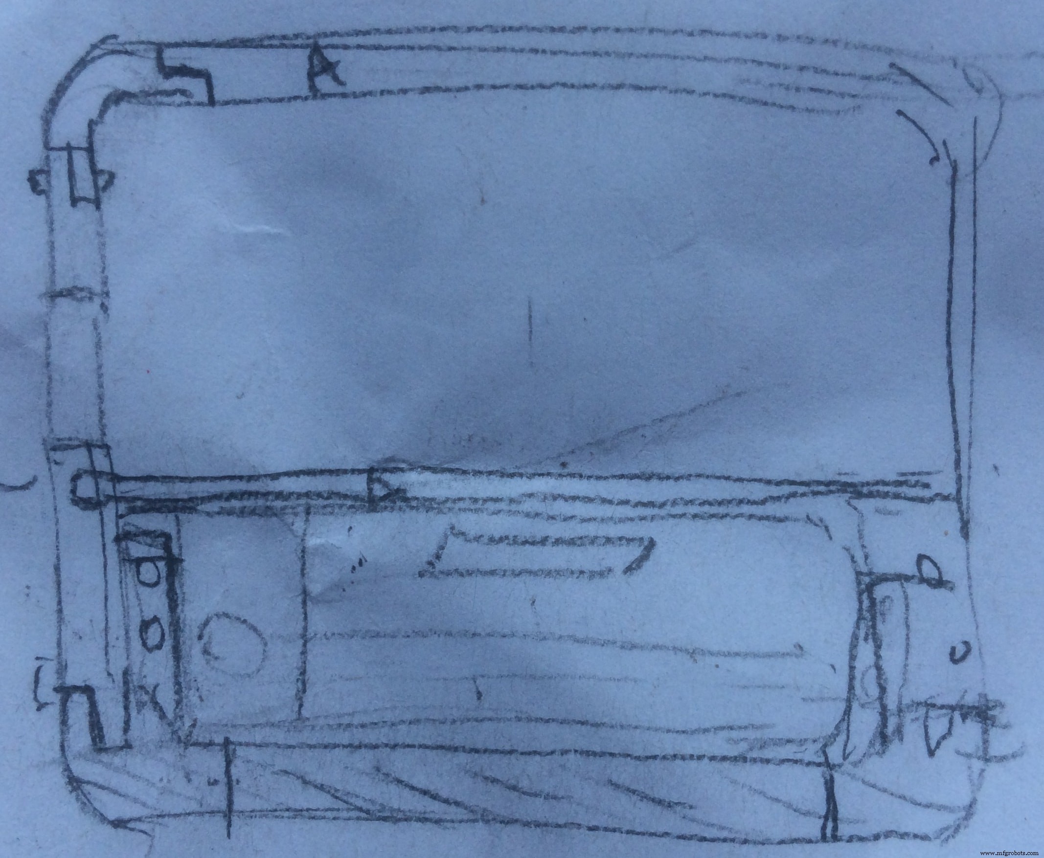
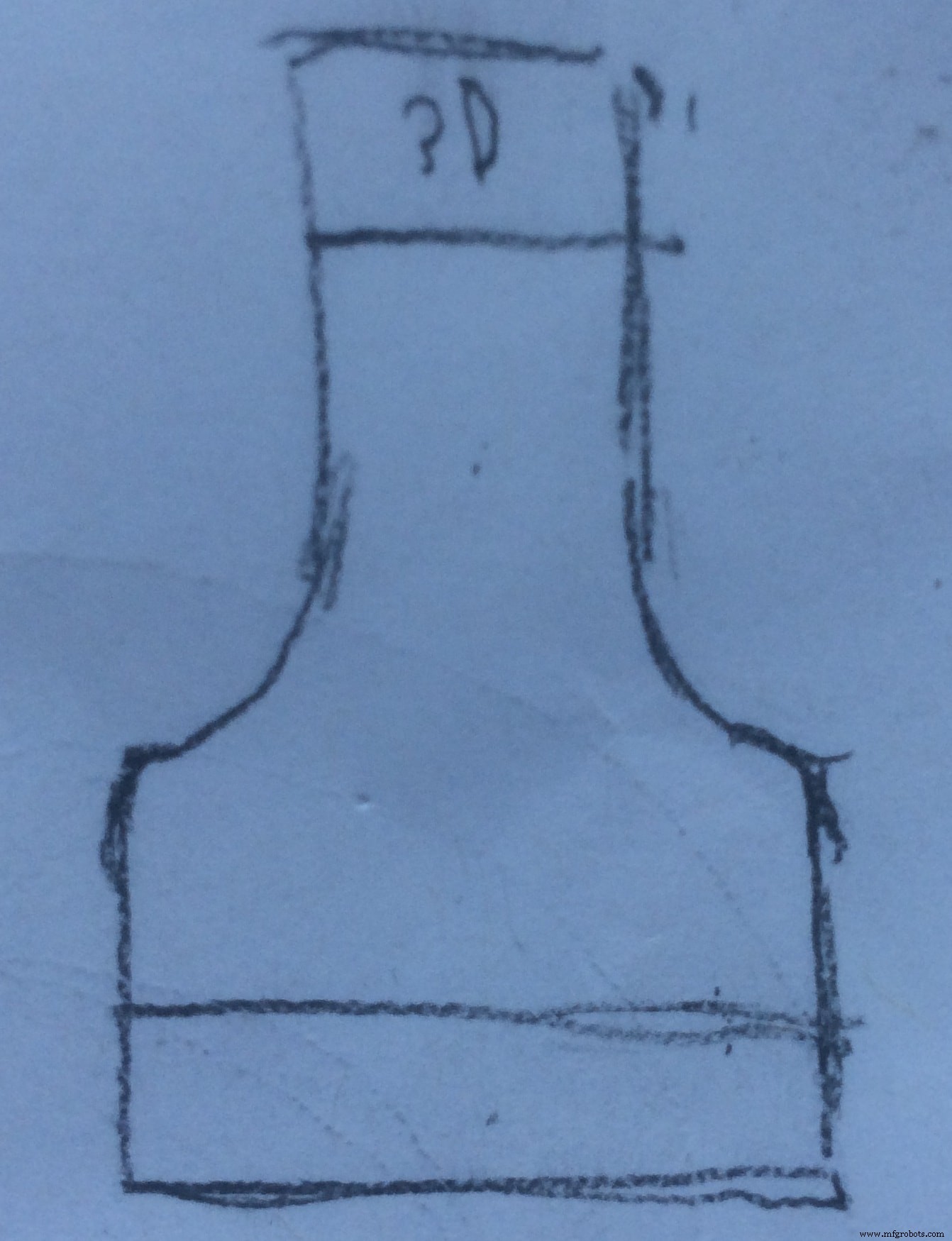
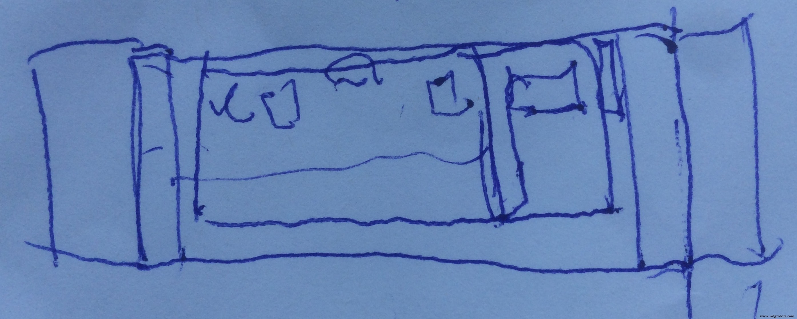
And this is the final 3D design:
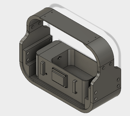
My sexy ass system :D
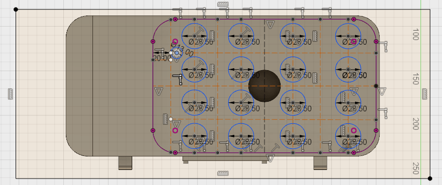
First thing which I designed was the water container . Here it is:
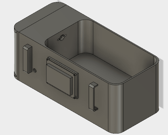
It incorporates several features! First, there is enough space for plants to grow, as well as in the middle I made a hole to place the Ultrasonic Atomizer. It is done because I wanted to level the fogger with the container. The thing is that the water level should be above the fogger by 2cm, so all the water which is leveled with the fogger hight, will not be used (waste)! So if I place the fogger below the container level, I have a water zero level exactly at the point where it should be, zero for the container =2cm above the fogger. In this way, all the water is used!
I also considered the hight of the container. Actually, all the dimensions of the container are measured during the experimental stage!
As you can see, I made a hole on the wall, which will be used for the cables from sensors placed in the water to hide into the electronics section. In the front of the container, I made the slot to attach the graphic display. I also designed some handles to easily remove the container when need!
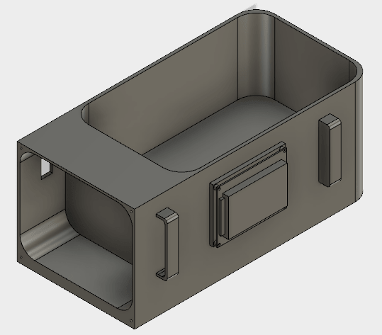
From this perspective, you can see the electronics section. Now its opened, but I also designed a lid to close it. Inside the electronics section, I designed a hole to have access to power and program the board
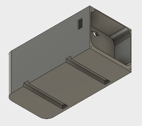
On the bottom side I designed sliders which will be attached to the rest of the system, and make it easier to remove the container when needed, it will also play a role of fixation of the container in place!
And now Let's Print It!
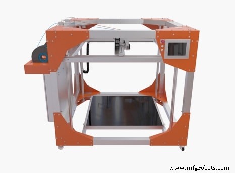
I can proudly announce that the printer which I will be using is called BigRep 3D Printer , only available in our FabLab Kamp-Lintfort. It has a capacity of one cubic meter, and provides the largest FFF build volume for professional and industrial use.
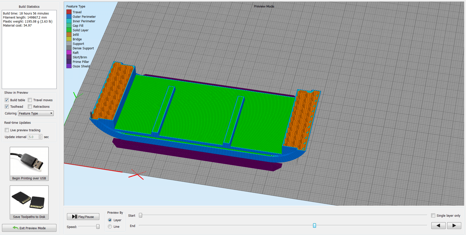
The slicing software which I use is Simplify3D , one of the most advanced slicing tools, in my opinion, with a lot of configurations and options.

I do not think that there is a right and a wrong way to print something, you just have to play with the settings until you find the best options for the specific object to print.
Because this printer is new, there are not too many testings made. So, I had to experiment with the settings, and try, try and again try...
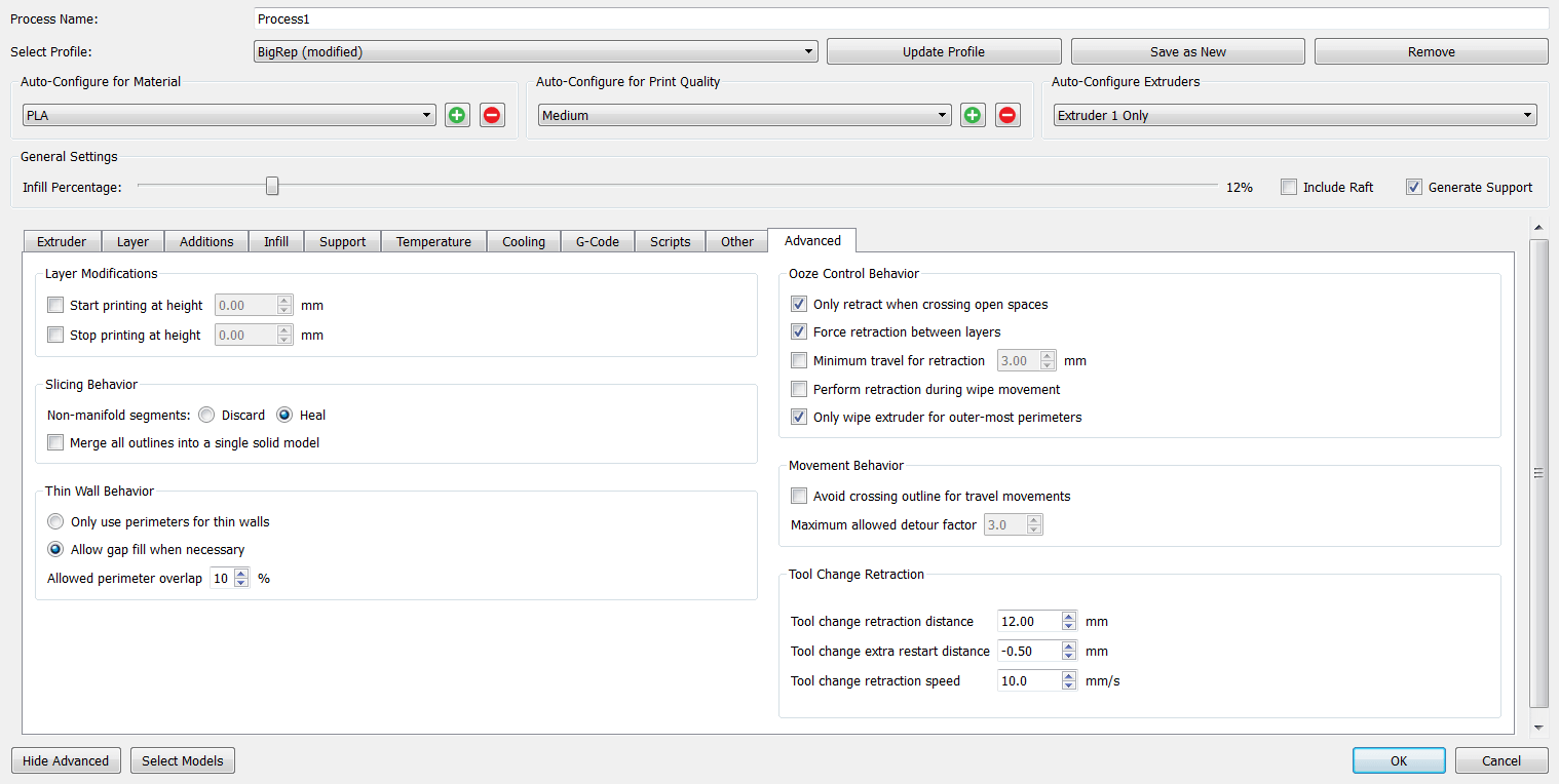
I will show bellow the settings that I will be using for my water container print, but some of them are intuitive.
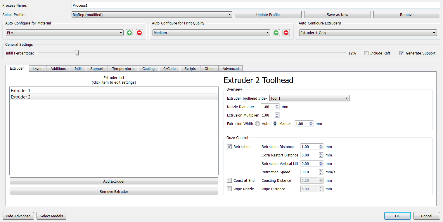
I choose the Tool1 , because the BigRep Printer has two nozzels with two different filaments, and I have to specify which nozzel I want to use, as well as the nozzle diameter and the rest of the settings.
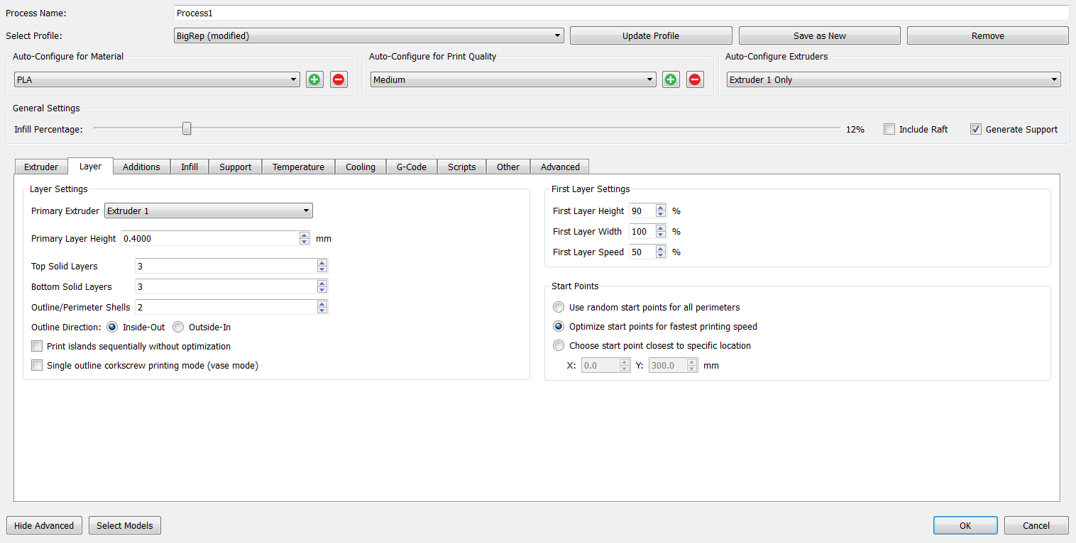
Layer:
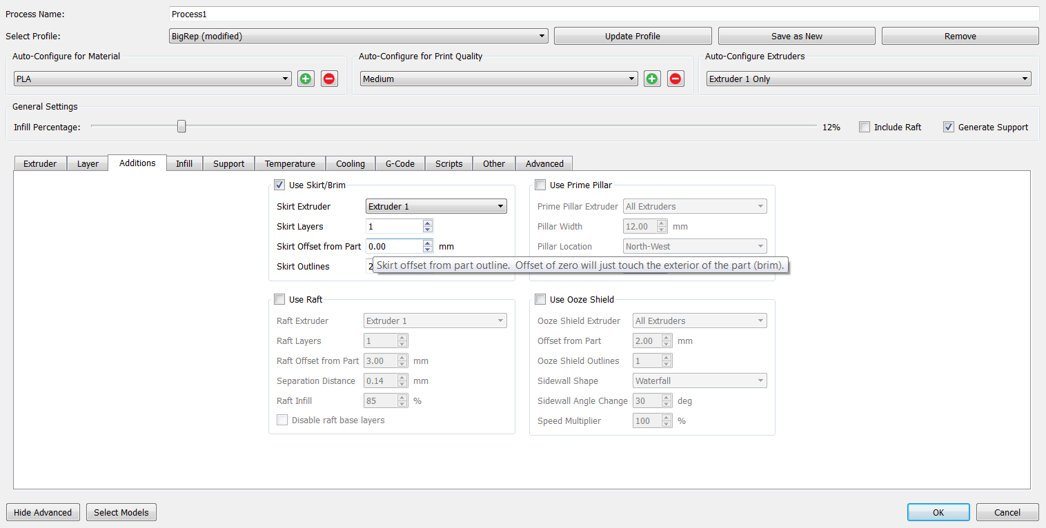
Additions:
Infill:
지원:
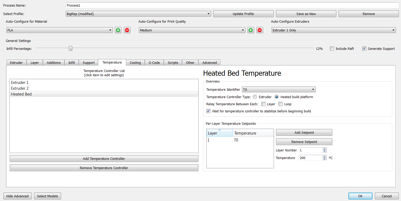
Temperature:
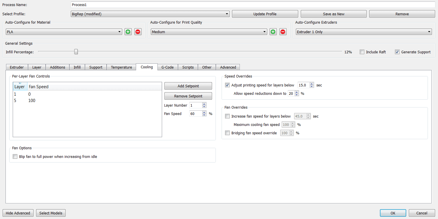
Cooling:
Other:

Advanced:
These are the changes that I made, the rest of the settings I just left by default.
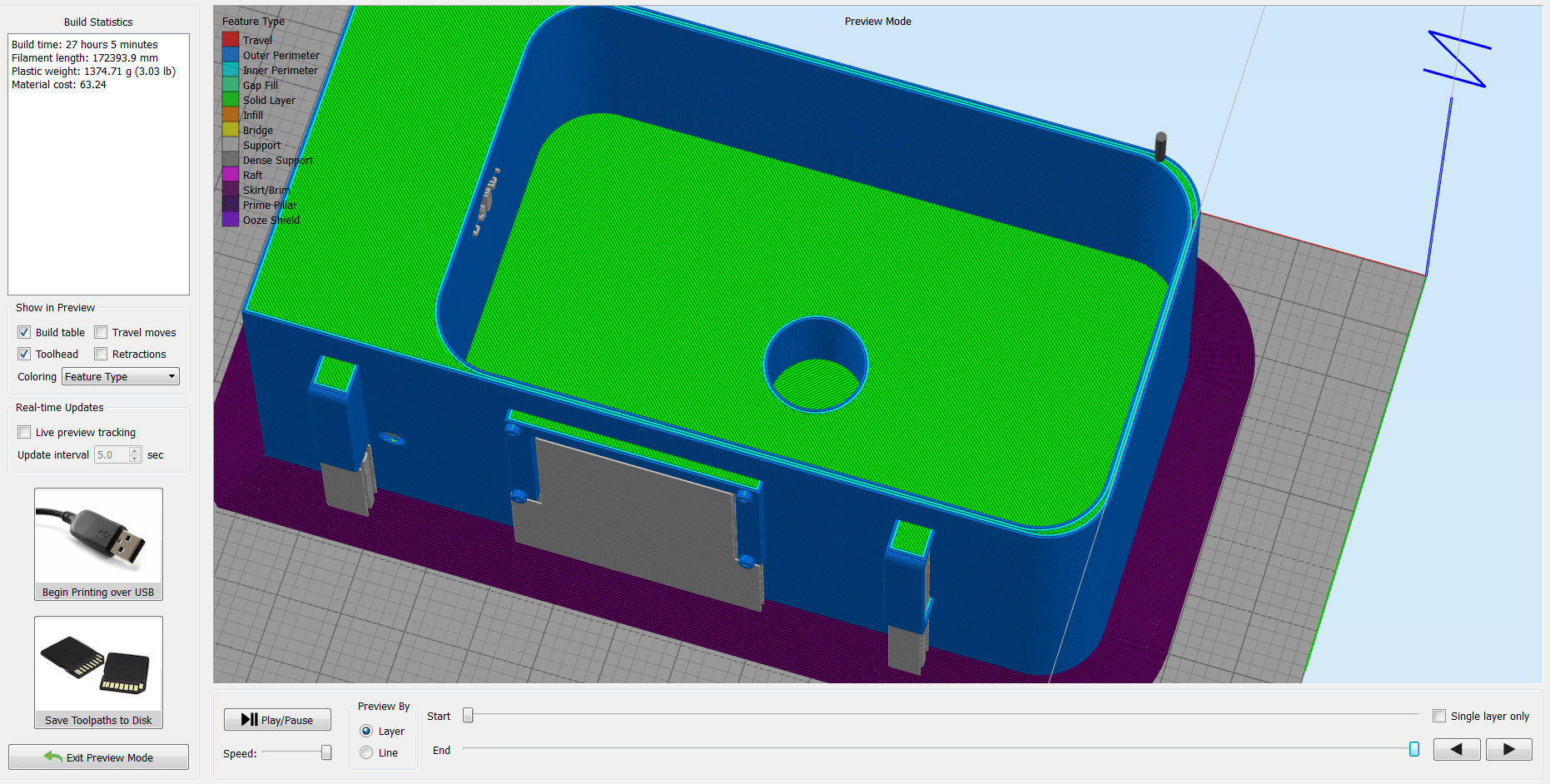
And then press on Prepare to Print . The software will generate the paths, and here we can check if everything is good, before sending the .gcode to the maschine.
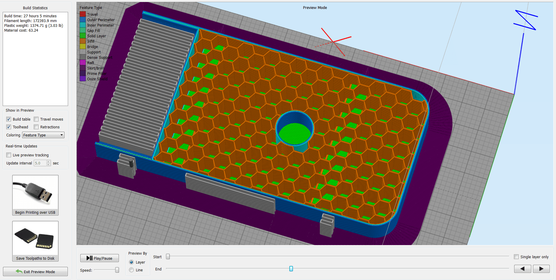
Briefly about some of the printer's settings. I used Nozzle Temperature =205 deg.C , and the Bed Temperature =70 deg.C . After I positioned the X, Y, and Z axis , and double checked all the settings, I launched the job!
This is how the raw model looks like:
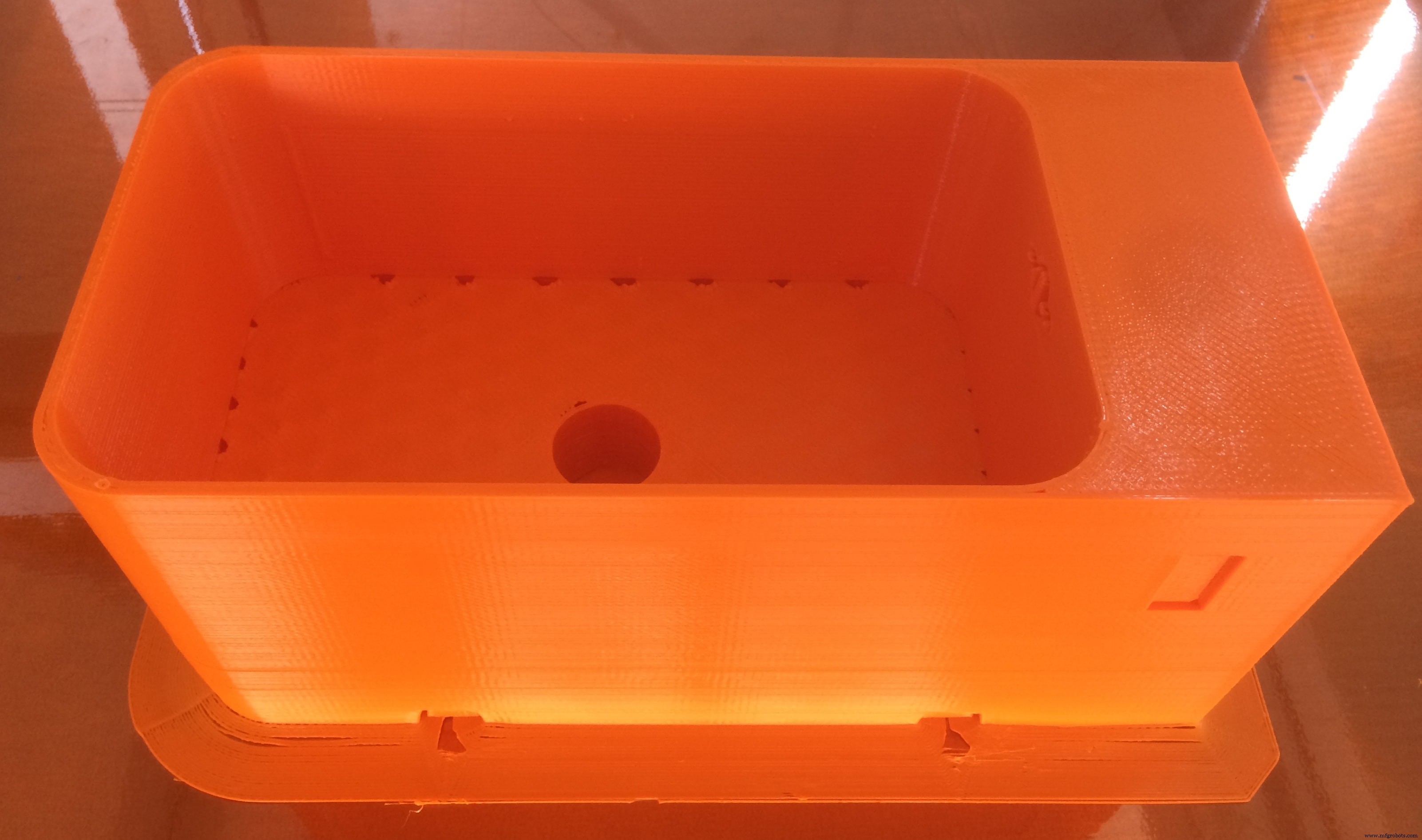
When I started removing the support and cleaning the model, I realized that this is a BIG pain in the ASS :D
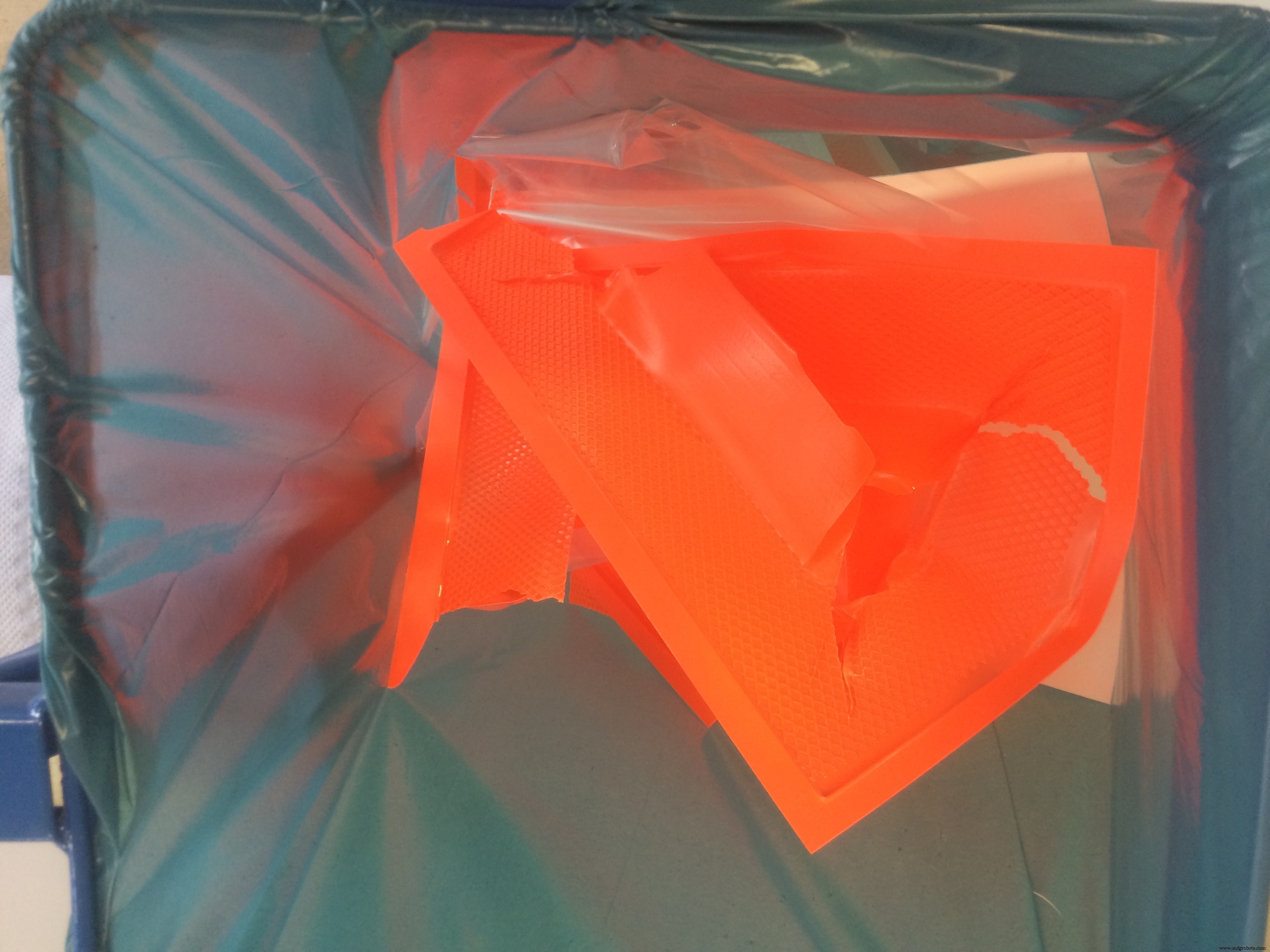
As you can notice, the settings which I used are not really perfect, because the container has some big holes next to the edges. I had in my mind to waterproof it anyway, you can see how I did it in the Moulding &Casting section!
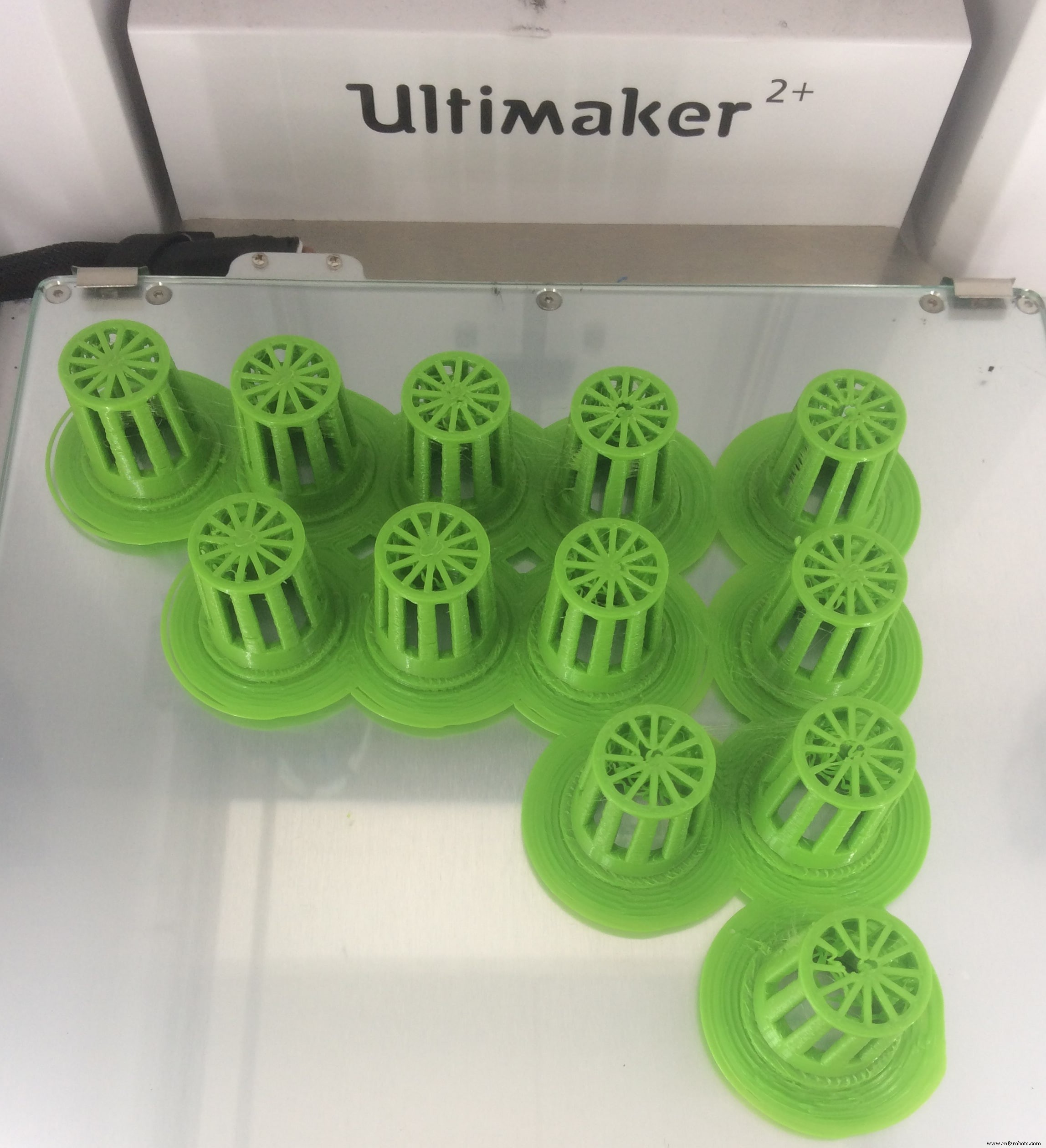
The next 3D printed part was the Net Pot . This is a cup which is designed to hold the seeds in the growing medium. More detailes about the first version of them you can see during my Computer-Aided Design week
This time I will improve the design a bit based on the observations that I made during the experimental stage. The main difference is the size of the empty space, which is increased a lot, to give an easier access for the fog to pass in, and for the roots to go through
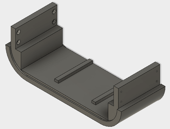
So I just modified the old design, and added one more thing!
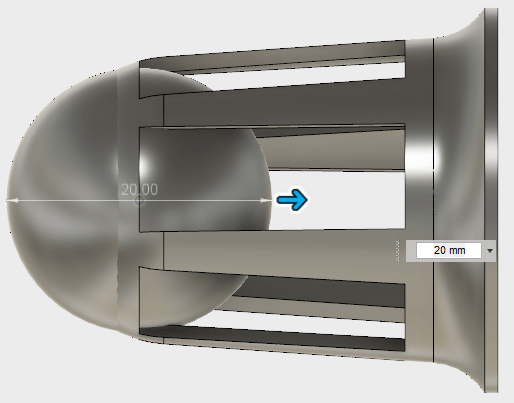
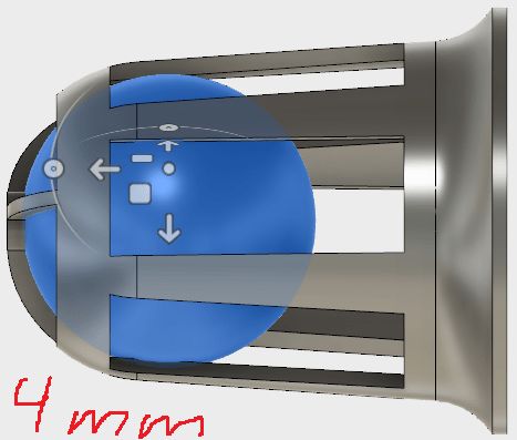
I made a slight fillet on the top part, to make the transition smoother. I also added a ball on the bottom, and used the Move command to move it a bit inside, and leave on the bottom around 2-3mm structure width
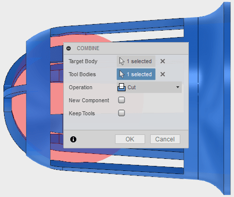
After I used the boolean substraction or Combine function, and I get this nice curviture at the bottom!
Now let's print it!
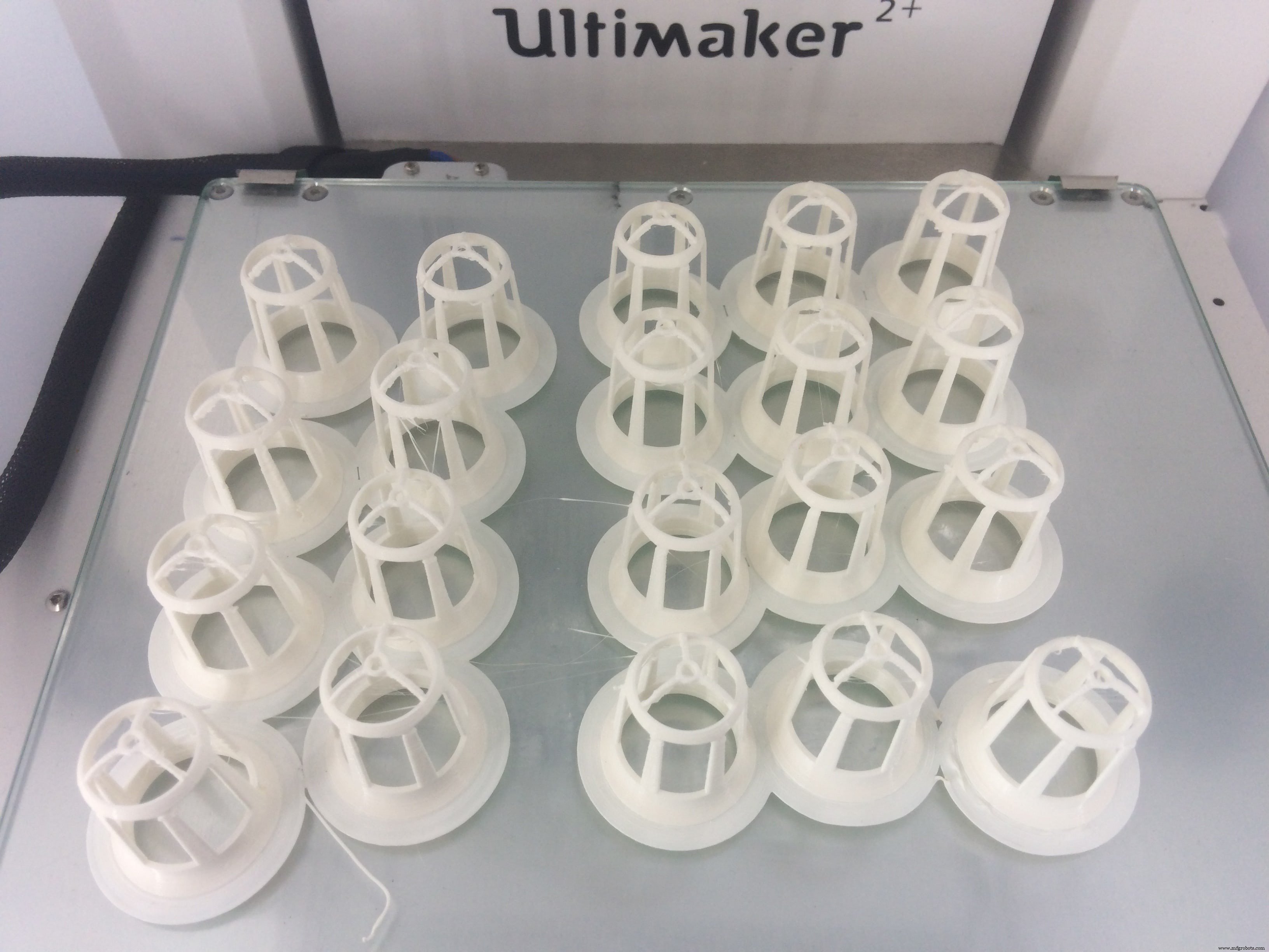
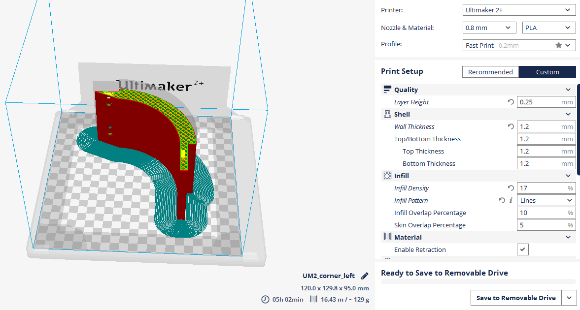
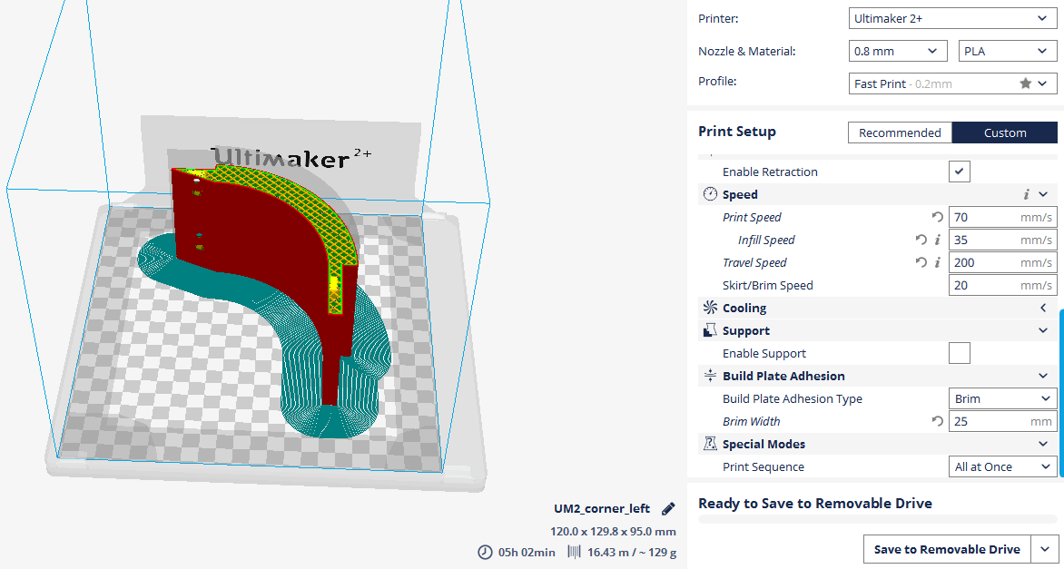
The 3D printer which I used is Ultimaker 2+ . To slice my 3D model, I will use, a very nice software, with an easy interface, and also functional. The material that I am using is PLA filament

After I import my .stl file, these are the settings that I am using:
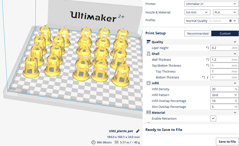
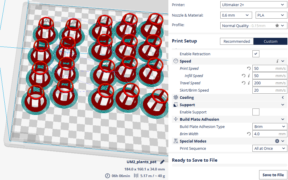
Here it is my little army :D
From the final design of the system, I decided to also 3D print the bottom part. Its a big piece, and I will use the BigRap as well for this.
I wouldn't say that there is anything new about this, because I used the same settings as I used for the water container , and more or less the rest is the same
Here is the preview of the print:
Another thing which I 3D printed are the rounded corners on the top side of the system. I used the Ultimaker for this, and used the following settings:
The trick here was to achieve maximum smoothness on the surface, and I think I got a pretty good result:

Download Files:
GIY System Design (.f3d)
Net Pot Design (.f3d)
2D Design &Laser Cutting
I used the Laser cutting technique to cut acrylic parts which will cover all the inside part of the system, and give it a finished look!
I actually did not design the parts again, I just exported the already created sketches from Fusion 360 as .dxf files . After I exported the file, I used to edit the design before importing it into the lasercut machine

This is how the sketch looks in Fusion360:
Looks like a big mess, but the good part is that everything is parametric! It looks messy because I had to align everything into the right position, and keep the stuff parametric in case I have to make a change later
This is how the final sketch looks in Rhino before lasercutting:
I decided to use a green acrylic piece because it gives an organic look, and combines well with the green plants
For the front and the back cover, I decided to use white color. Its all about the taste, this is the way I see it, and this is how I like it.
The front and the back cover are very similar, have the same dimensions, except the inside cuts! The front cover has the hole for the LCD Display, here it is:

For the back cover, I want to make a hole to have access to power and program the board! This is how it looks:

Another lasercutted piece is on the top! I decided to use a transparent acrylic part, in order for the light to go through! I also designed some additional cuts, to decrease the weight, and give more space for the light to pass! I also measured the width of the RGB LED stripes, and will attach them in a way that there is enough room for the sunlight as well as artificial light!

I finished with the design, and now Let's Laser Cut!
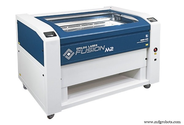
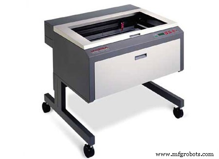
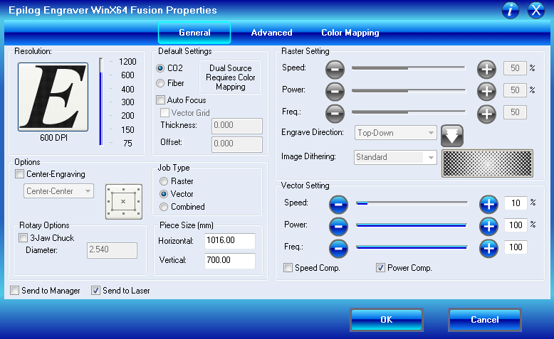
The Laser Cutter that we are using here in FabLab is Epilog Fusion 60Watt, a CO2 lasercutter with a working area of 1016 x 711 mm. It can cut and ingrave materials like wood, cardboard, acrylic or other engineered plastics.
Because I used the same material for all the pieces, plexiglass 5mm , I used the same settings for all of them!
Download Files:
Front / Back Cover (.dxf)
Plant Holder (.dxf)
LED Light Holder (.dxf)
CNC Milling
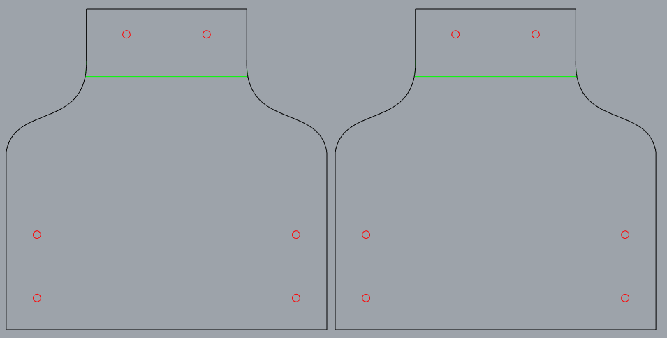
Because I wanted to integrate in my system all the skills and techniques that I learned, I also have a piece of structure to CNC mill. I did not design it again, but I exported the .dxf file from Fusion360 sketch!
To cut my design, I will be using the big CNC monster.
A CNC (computer numerically controlled) is a machine that uses a cutting bit that rotates at a very high speed to remove material from a part.
The machine reads a pre‐programed computer file telling it where and how to cut, usually .GCode 파일. A cutting bit is rotated at a very high RPM by a spindle motor, which can move the bit up and down. This mechanism is moved left, right, front, and back by a cross arm. The machine is therefore known as a three‐axis router because it can move on the X, Y &Z axis. The machine can do two dimensional cutouts and etching, as well as three‐dimensional relief work.
In FabLab Kamp-Lintfort we have a CNC portal milling machine by e(sign:Easy Worker MasterPro 2513.

It’s working area is 2600 x 1400 x 300mm and it comes with a vacuum table. We primarily use it for wood milling but with its HSD Spindel (3.9KW; 24.000U/min) it is also capable to mill metals easily.
The material which I will be using is 18mm Plywood
At first, I place the wood sheet on the CNC bed, and after I aligned it, switch on the vacuum. After I exported the .dxf file, I used to edit the design before importing it into the machine CAM software.
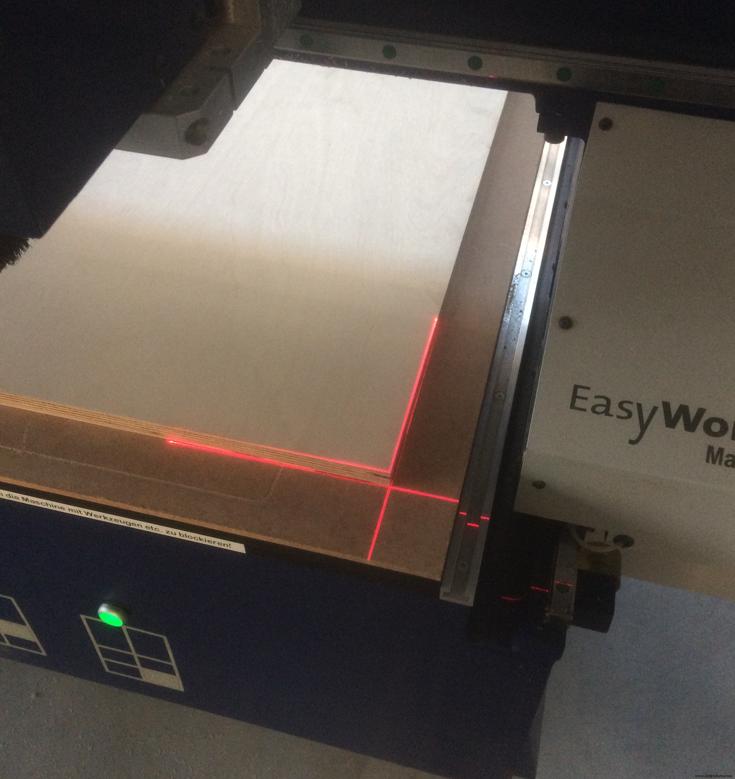
First, I have to HOME the machine!
To set the X, Y and Z Zero Positions, I home the machine by pressing the home button in the software (or on the remote control).
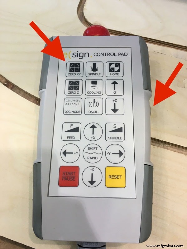
At first, I can set my zero X and Y roughly aligned to one of the corners of the bed. We also tried to use the laser for this, but all the time when simulating the process, it was showing collisions, because the zero was going out of the working area
Now I have to find the Z axis, which I do using the special tool which comes with the machine:
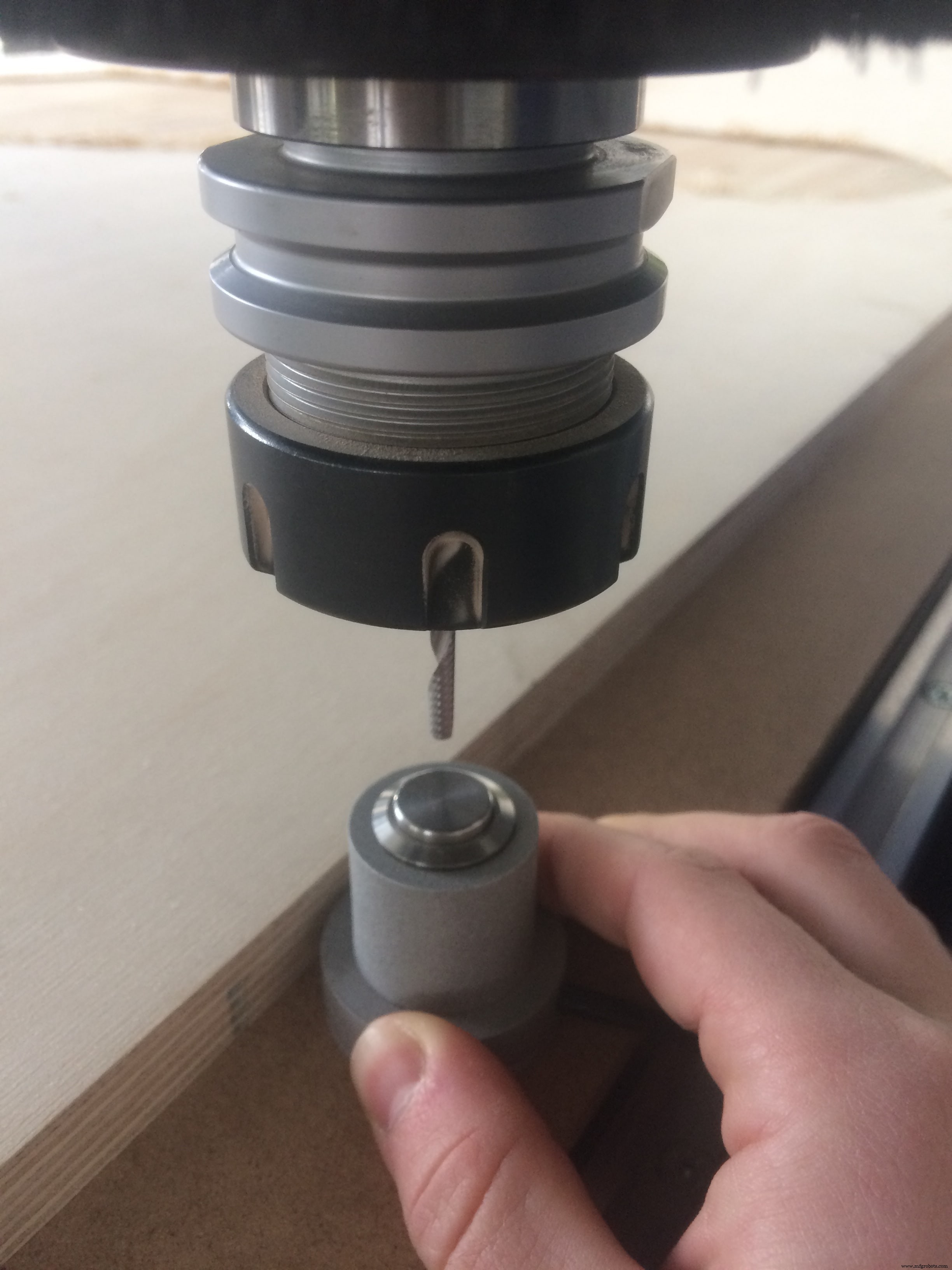
Important thing is to place it on the bed of the machine!
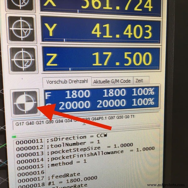
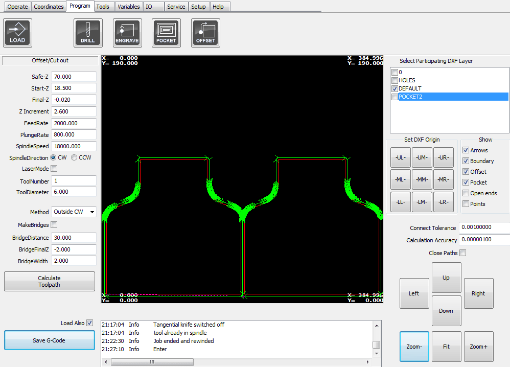
Now I can launch the first job, which is making the engraving. These are the settings which I used:
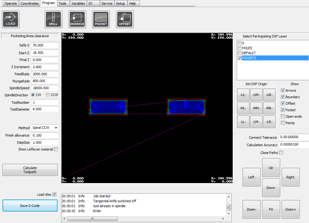
I press Calculate Toolpath to simulate the job and make sure that there are no collisions! After I save the .GCode , and launch the job, I get this window:
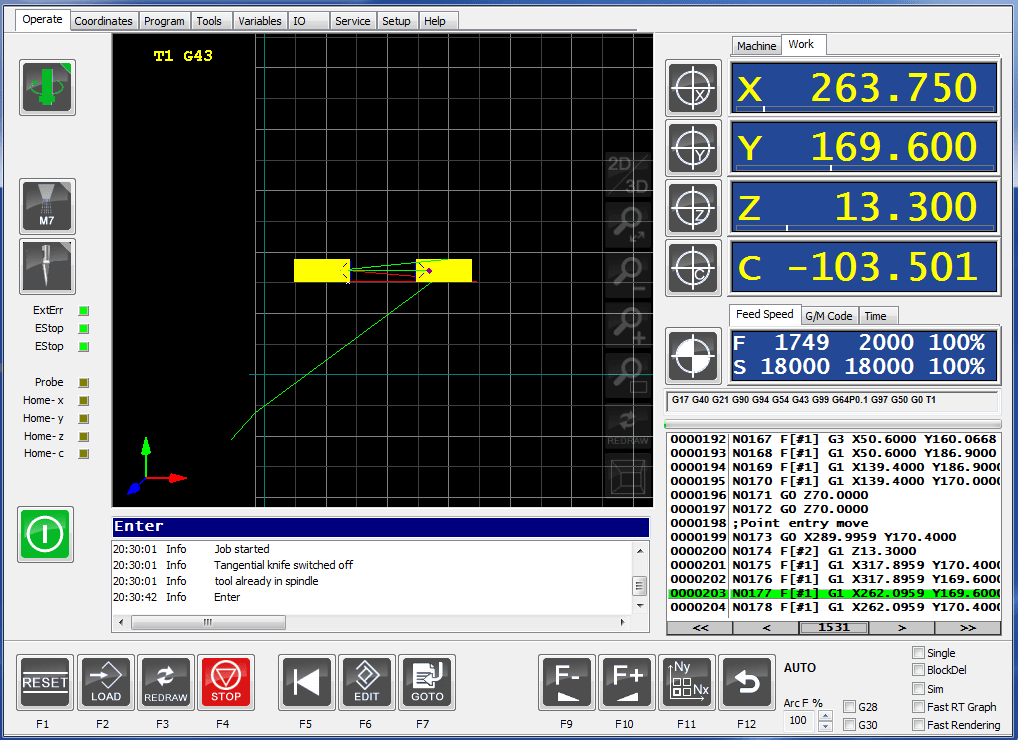
Now I can launch the outside cut:

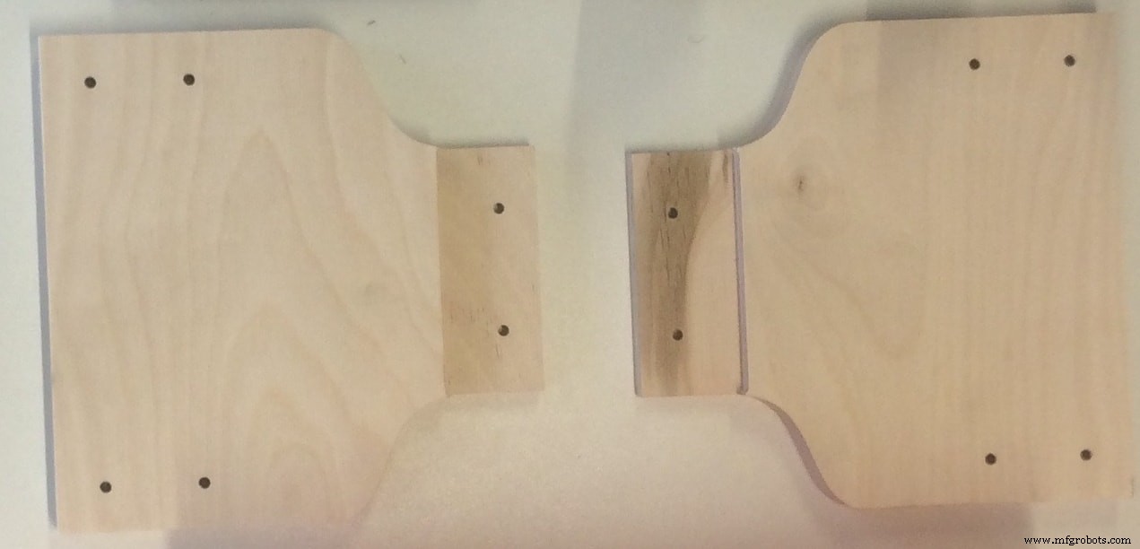
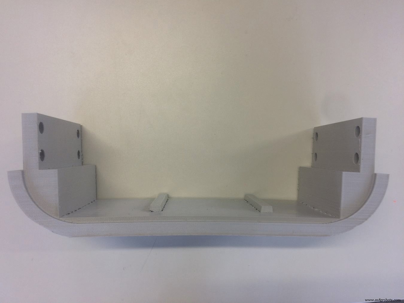
This is what I get after the job is done:
Another piece which I had to mill is used for the Moulding &Casting section!
I prepared the mould to waterproof my water container. Here is the design:

There is nothing new about this. I used exactly the same settings as above. The only thing is the material thickness was 10mm wood , and I had to cut 7 pieces, to glue them together later and prepare my mould!
Download Files:
Structure Walls (.dxf)
Mould (.dxf)
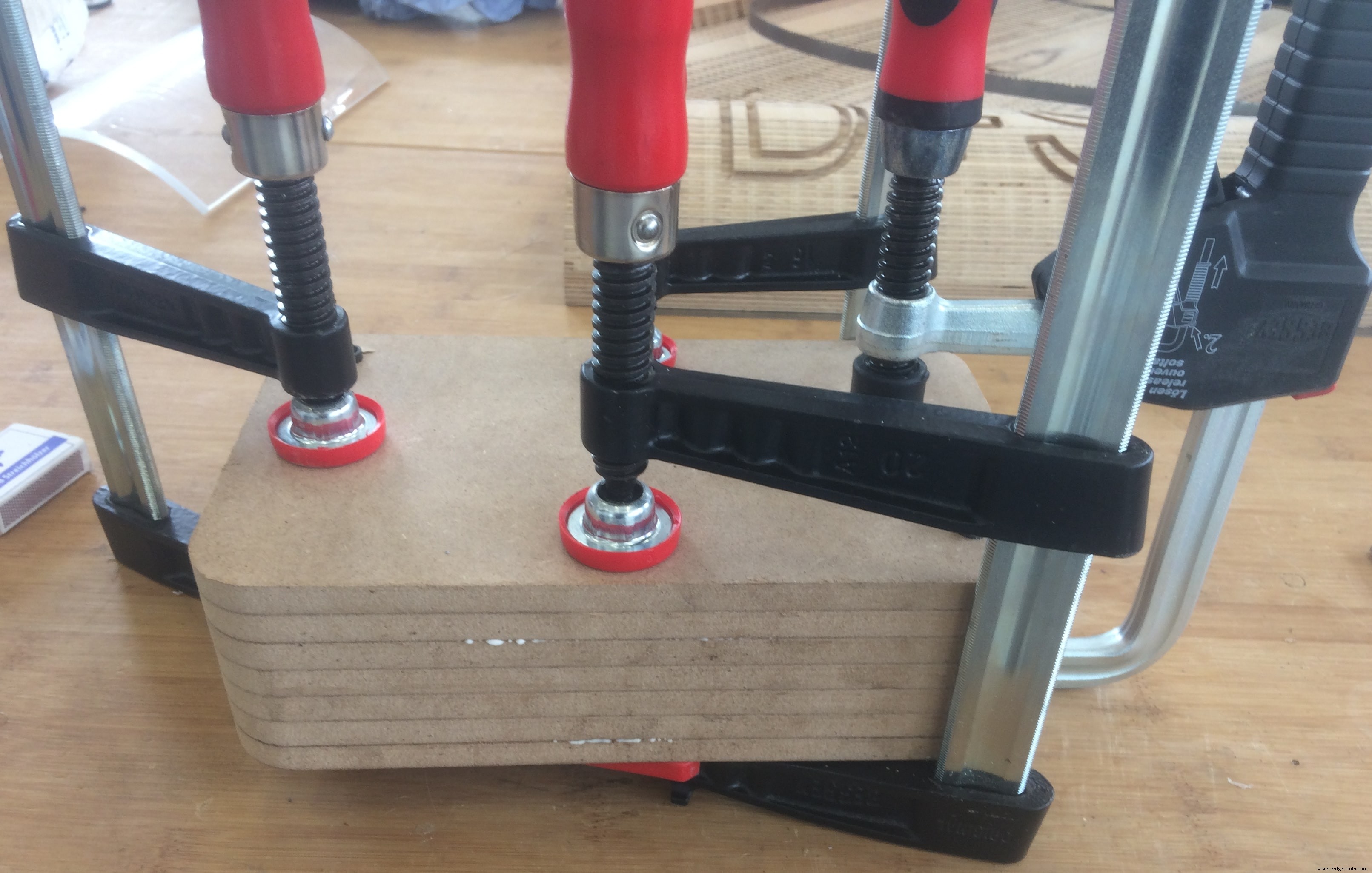
Moulding &Casting
I used this technique in order to prepare a water container, to waterproof my existing container! I see it as a thin layer of material (a smaller container) which can be easily removable!
This is the result from the previous section CNC Milling
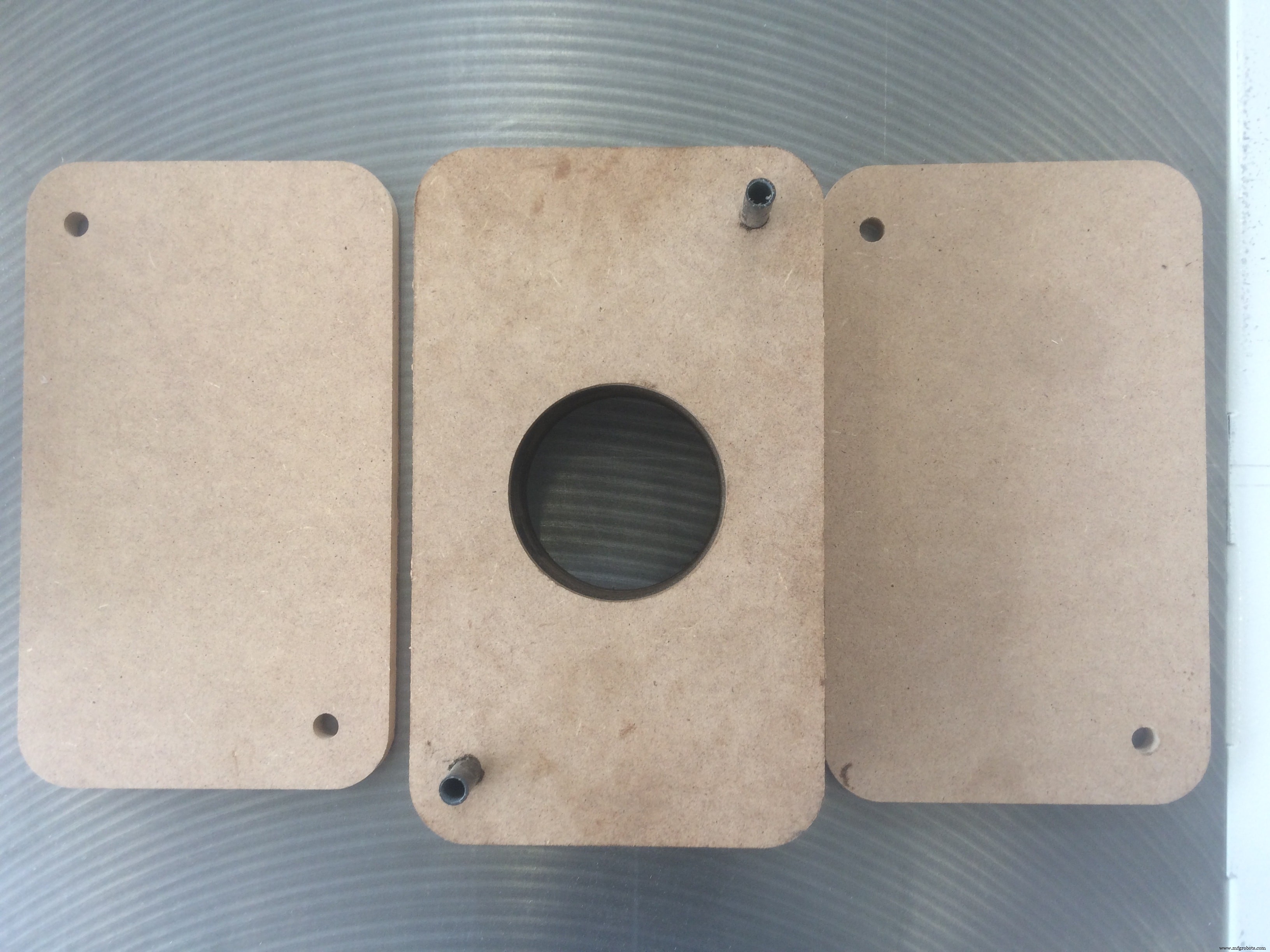
I cut 7 identical pieces, and aligned them using the reference holes! I also cut a big hole in the middle of 5 bottom pieces , in order to place the air pump inside, and easily remove the cast later.
After I glued all the pieces together, and fixed them, this is how it looks:
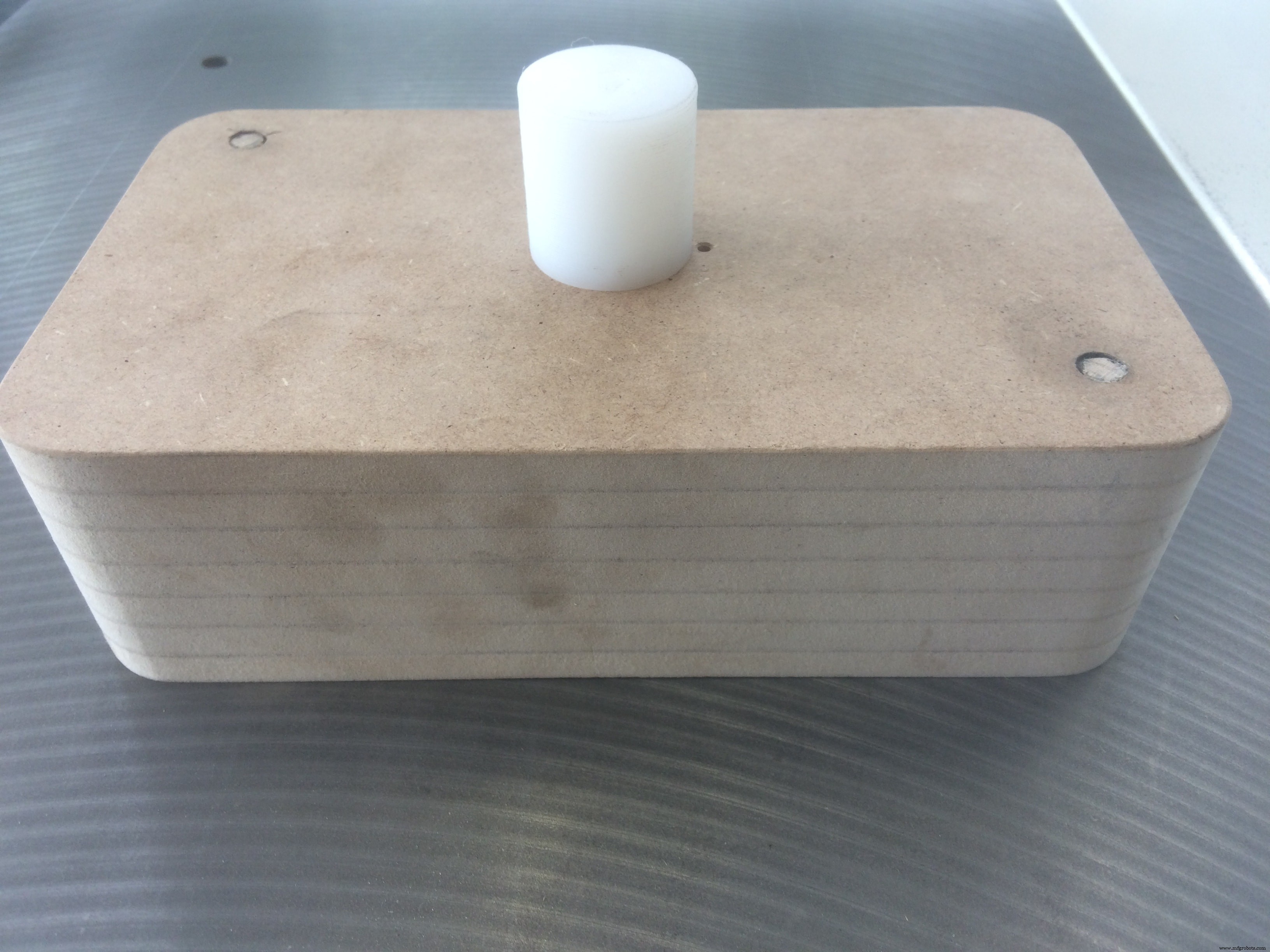
While waiting for the glue to dry out, I prepared a little plastic "thing" (do not know how to call it :D) for the pump. The idea is to be able to screw it on my mould, and remove it whenever I want!
When the mould is ready, this is how it looks:
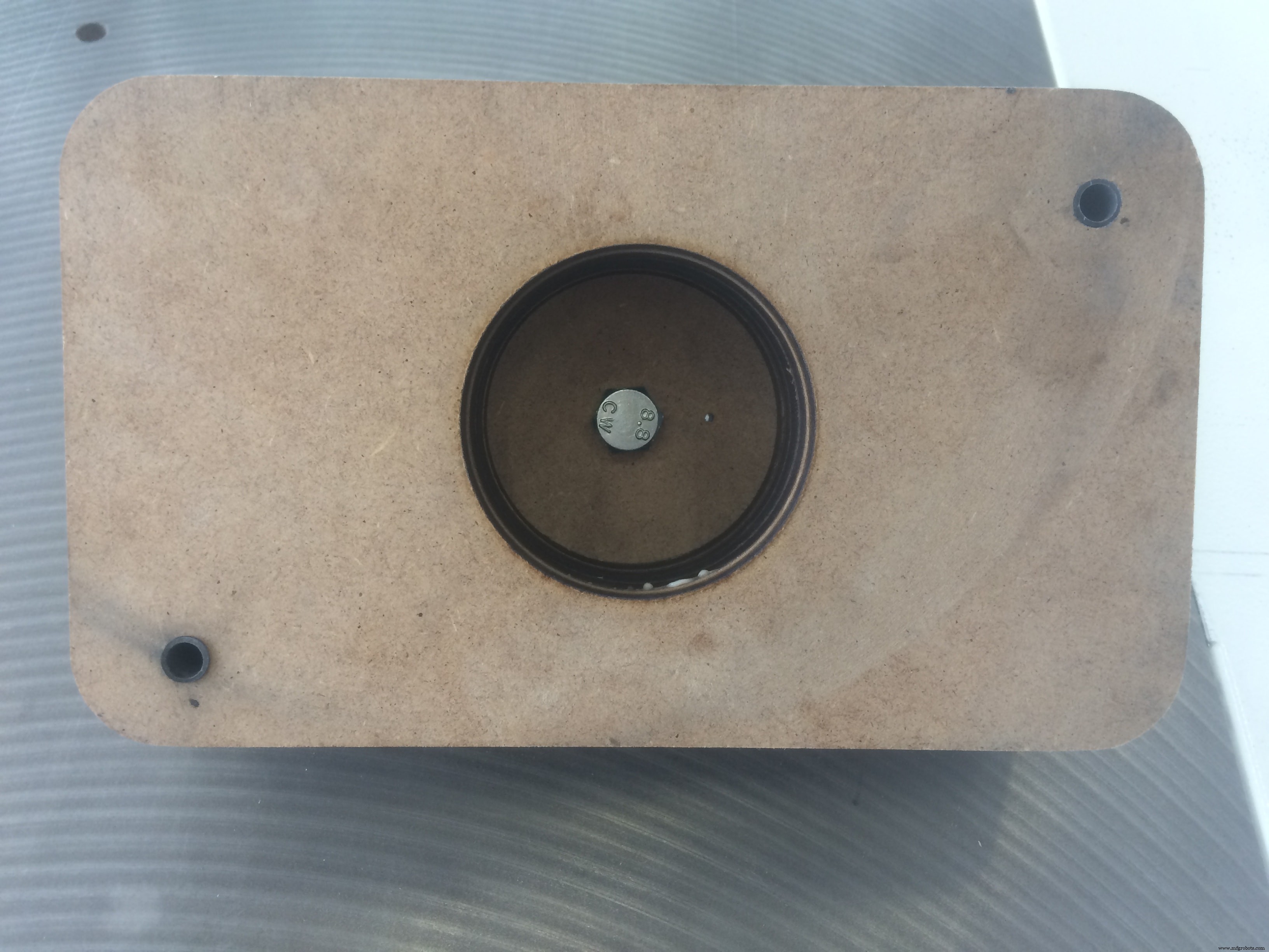
And the back side:
I am ready to vacuum cast!
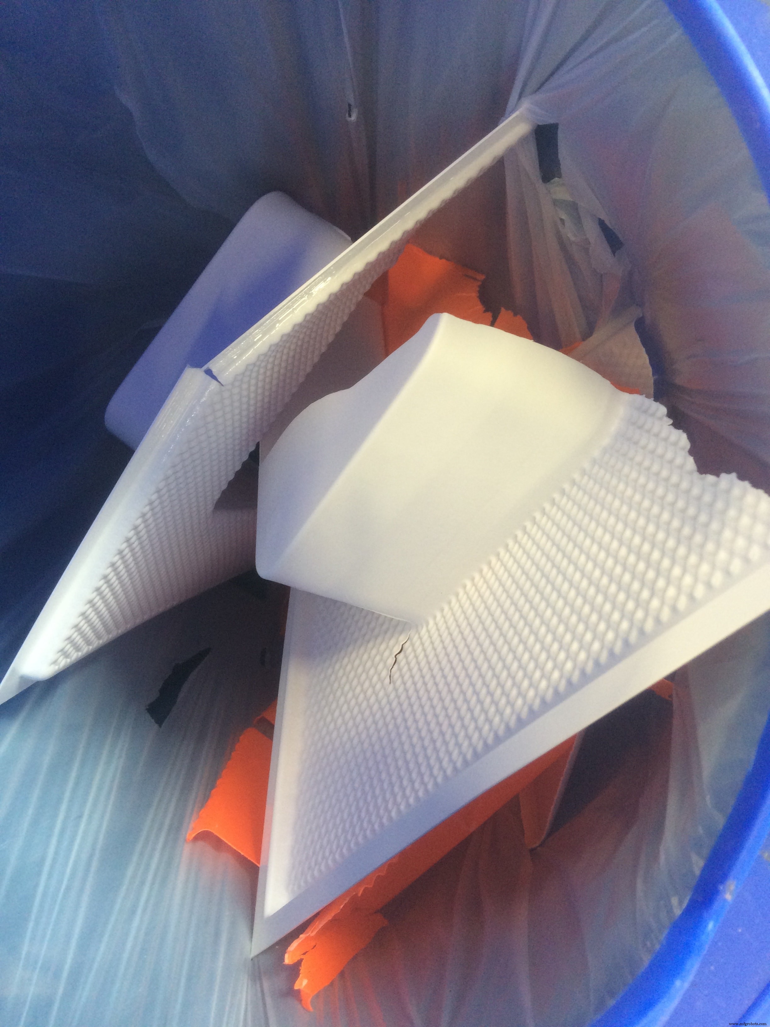
I used a vacuum machine available in our FabLab Kamp-Lintfort called Formech – Manual Vacuum Forming Machine
The thing is that I tried to do it many times, and all the time I could not remove the mould without breaking the cast! After several hours of trials, I came up with a solution! First, I vacuum casted one thin layer of material, and without removing it, I will cast the actual container on top of it. The first thin layer is slippery, and If I spray it with silicon, it will allow me to remove the mould way easier
After I let the silicon to dry a bit, I can cast the actual layer!
And here we are!!!
A hero shot for those who may thing that it was easy
Putting All Together
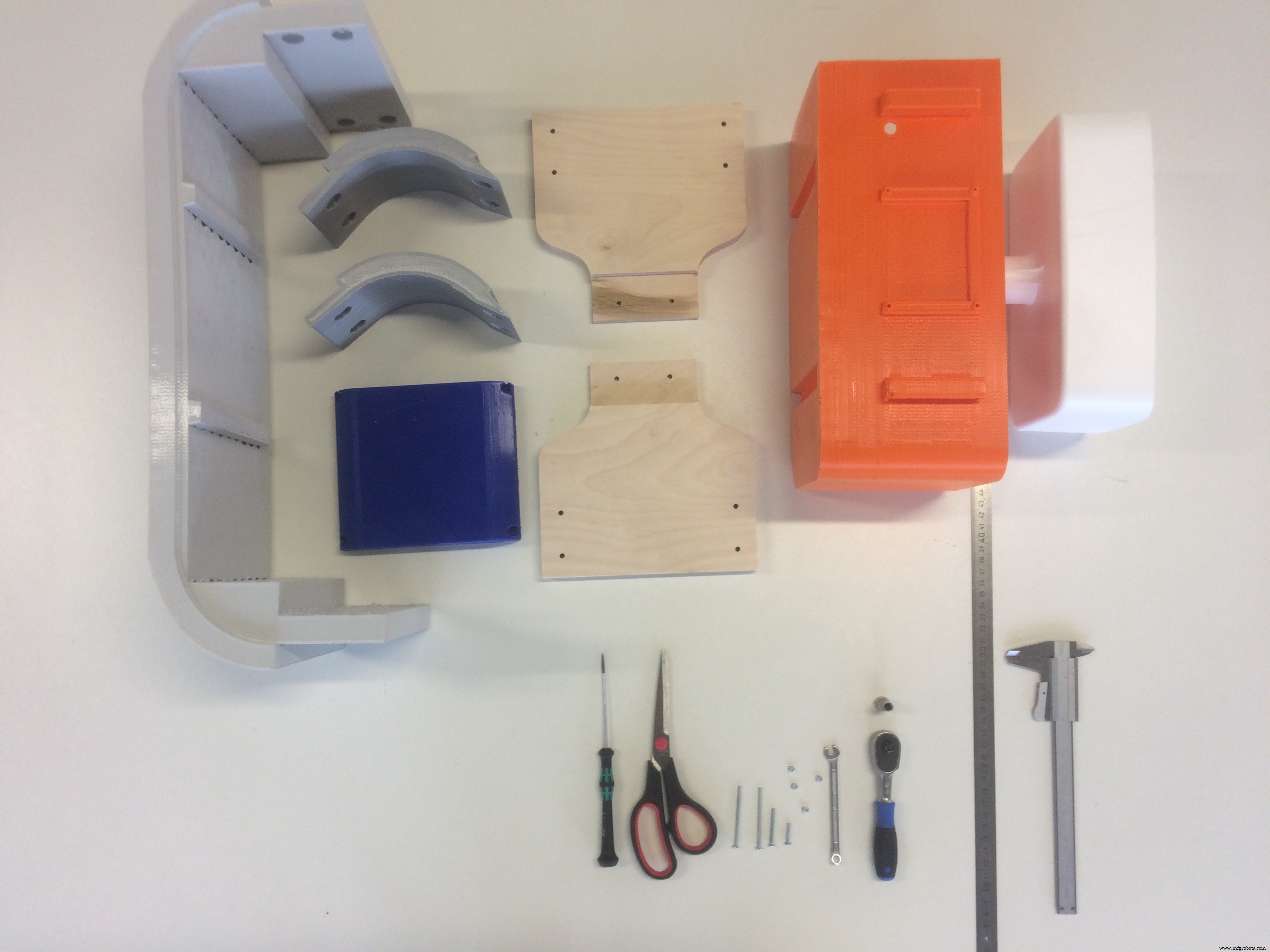
Now, let's put everything together! I will start by assembling the structure. Put next to me all the necessary tools:
A short animation of the process:
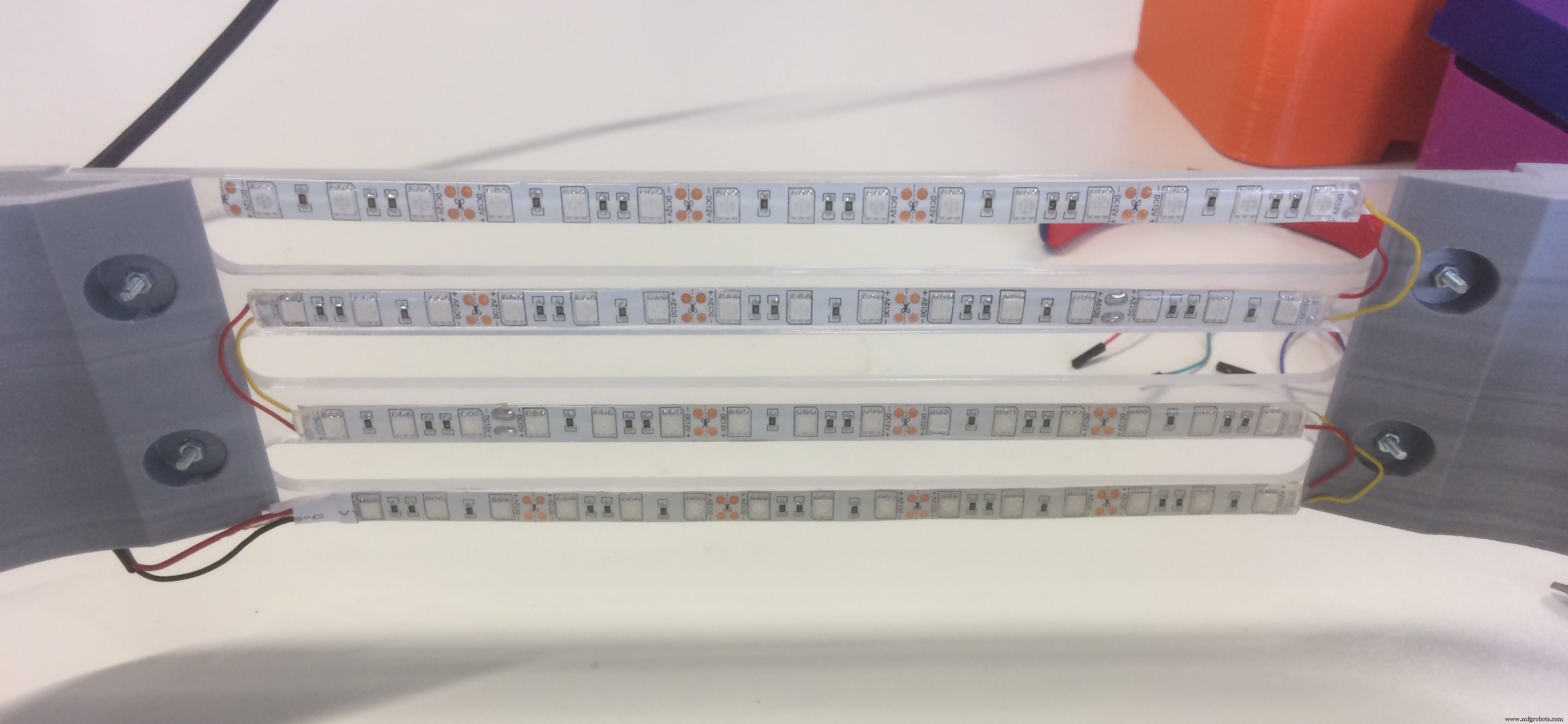
To assemble the lights, I cut the RGB LED stripes into 4 pieces (I measured the length in advance), and soldered them accordingly!
After I connected all the sensors, and managed the wiring, I fixed the board in the electronics section
And here it is the system!!! Everything assembled, nice looking growing system GIY
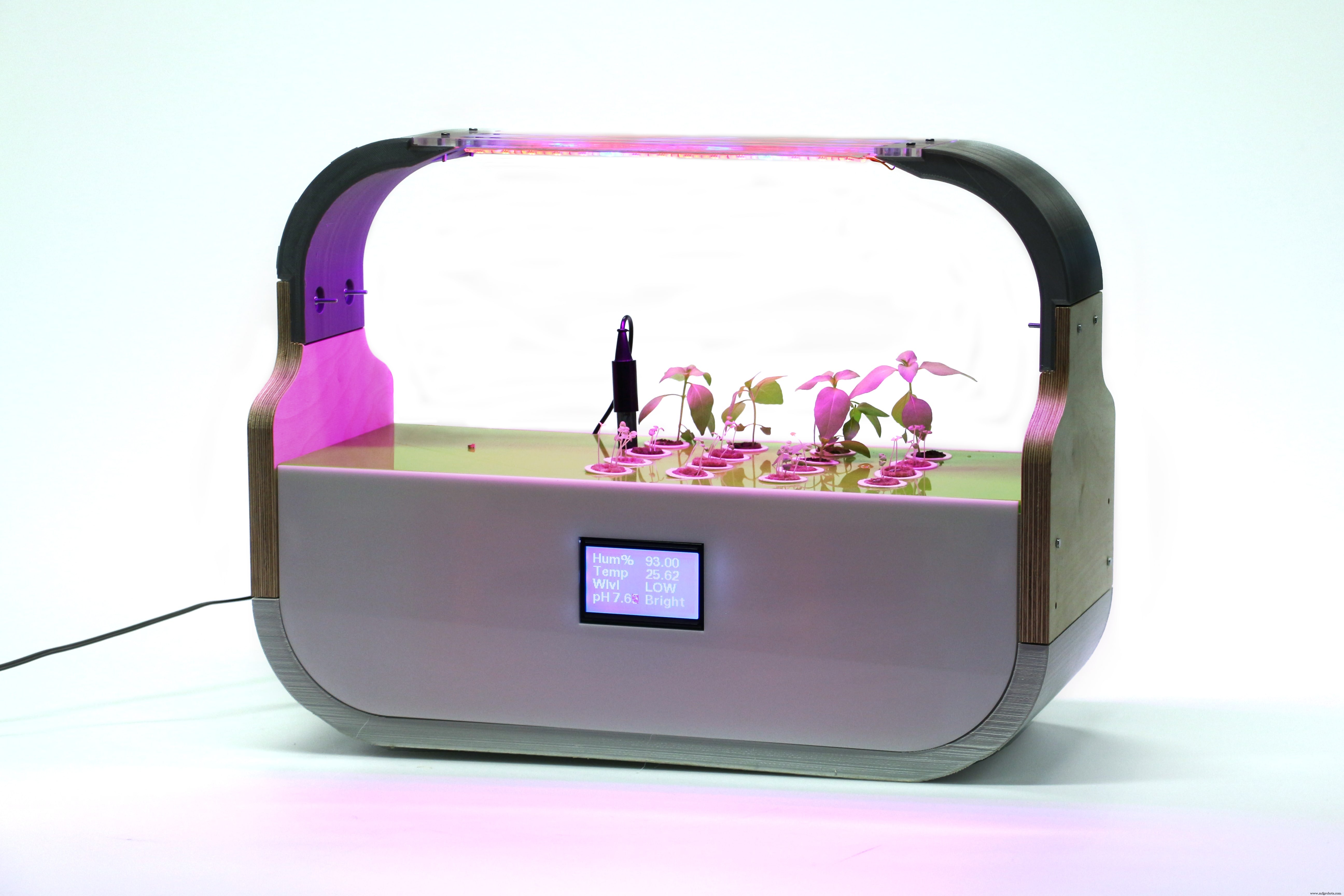
A HERO shot during the working process!
Final Presentation Video
© 2017 Albot Dima. All rights reserved | [email protected]
This work is licensed under a Creative Commons Attribution-NonCommercial-ShareAlike 4.0 International License.

For 더 details about project, please visit official source:
http://archive.fabacademy.org/2017/fablabkamplintfort/students/396/final.html
<섹션 클래스="섹션 컨테이너 섹션 축소 가능" id="코드">#include "dht.h"#include "U8glib.h"#include#include #define DHT11_PIN 2 // what digital pin we're connected to#define ONE_WIRE_BUS 3#define WATER_LEVEL A4#define LDR_PIN A3#define PH_PIN A5#define GROW_LIGHT 10#define FOG_PUMP 13int waterLevel;int LightLevel;int pH;dht DHT;OneWire oneWire(ONE_WIRE_BUS); DallasTemperature waterTemp(&oneWire);U8GLIB_ST7920_128X64 u8g(4, 12, 6, U8G_PIN_NONE);const unsigned char logo [] PROGMEM ={0xFF, 0xFF, 0xFF, 0xFE, 0x7F, 0xFF, 0xFF, 0xFF, 0x00, 0x00, 0x00, 0x00, 0x00, 0x00, 0x00, 0x00,0xFF, 0xFF, 0xFF, 0x00, 0x00, 0xFF, 0xFF, 0xFF, 0x00, 0x00, 0x00, 0x00, 0x00, 0x00, 0x00, 0x00,0xFF, 0xFF, 0xF8, 0x00, 0x00, 0x1F, 0xFF, 0xFF, 0x00, 0x00, 0x00, 0x00, 0x00, 0x00, 0x00, 0x00,0xFF, 0xFF, 0xC0, 0x00, 0x00, 0x03, 0xFF, 0xFF, 0x00, 0x00, 0x00, 0x00, 0x00, 0x00, 0x00, 0x00,0xFF, 0xFF, 0x00, 0x00, 0x00, 0x00, 0xFF, 0xFF, 0x00, 0x00, 0x00, 0x00, 0x00, 0x00, 0x00, 0x00,0xFF, 0xFE, 0x00, 0x03, 0xC0, 0x00, 0x7F, 0xFF, 0x00, 0x00, 0x00, 0x00, 0x00, 0x00, 0x00, 0x00,0xFF, 0xF8, 0x00, 0x07, 0xE0, 0x00, 0x3F, 0xFF, 0x00, 0x00, 0x00, 0x00, 0x00, 0x00, 0x00, 0x00,0xFF, 0xF0, 0x00, 0x1F, 0xF8, 0x00, 0x0F, 0xFF, 0x00, 0x00, 0x00, 0x00, 0x00, 0x00, 0x00, 0x00,0xFF, 0xE0, 0x00, 0x3F, 0xFE, 0x00, 0x07, 0xFF, 0x00, 0x00, 0x00, 0x00, 0x00, 0x00, 0x00, 0x00,0xFF, 0xC0, 0x00, 0 x18, 0x1F, 0x00, 0x03, 0xFF, 0x00, 0x00, 0x00, 0x00, 0x00, 0x00, 0x00, 0x00,0xFF, 0x80, 0x00, 0x00, 0x03, 0xC0, 0x01, 0xFF, 0x00, 0x00, 0x00, 0x00, 0x00, 0x00, 0x00, 0x00,0xFF, 0x00, 0x00, 0x00, 0x00, 0xF0, 0x00, 0xFF, 0x00, 0x00, 0x00, 0x00, 0x00, 0x00, 0x00, 0x00,0xFE, 0x00, 0x00, 0x00, 0x00, 0x7C, 0x00, 0x7F, 0x00, 0x00, 0x00, 0x00, 0x00, 0x00, 0x00, 0x00,0xFC, 0x00, 0x00, 0x00, 0x00, 0x3E, 0x00, 0x7F, 0x00, 0x00, 0x00, 0x00, 0x00, 0x00, 0x00, 0x00,0xFC, 0x03, 0x80, 0x00, 0x00, 0x3F, 0x80, 0x3F, 0x00, 0x00, 0x00, 0x00, 0x00, 0x00, 0x00, 0x00,0xF8, 0x07, 0xE0, 0x00, 0x00, 0x1F, 0xE0, 0x1F, 0x00, 0x00, 0x00, 0x00, 0x00, 0x00, 0x00, 0x00,0xFC, 0x1F, 0xF0, 0x00, 0x00, 0x1F, 0xF0, 0x1F, 0x00, 0x00, 0x00, 0x00, 0x00, 0x00, 0x00, 0x00,0xF0, 0x3F, 0xF0, 0x00, 0x00, 0x1F, 0xFC, 0x0F, 0x00, 0x00, 0x00, 0x00, 0x00, 0x00, 0x00, 0x00,0xF0, 0xFF, 0xF0, 0x00, 0x00, 0x1F, 0xFF, 0x0F, 0x00, 0x00, 0x00, 0x00, 0x00, 0x00, 0x00, 0x00,0xE0, 0xFF, 0xF0, 0x00, 0x00, 0x3F, 0xFF, 0x07, 0x00, 0x00, 0x00, 0x0 0, 0x00, 0x00, 0x00, 0x00,0xE0, 0xFF, 0xF0, 0x00, 0x00, 0x3F, 0xFF, 0x07, 0x00, 0x00, 0x00, 0x00, 0x00, 0x00, 0x00, 0x00,0xC0, 0xFF, 0xF8, 0x00, 0x00, 0x7F, 0xFF, 0x03, 0x00, 0x00, 0x00, 0x00, 0x00, 0x00, 0x00, 0x00,0xC0, 0xFF, 0xFC, 0x00, 0x00, 0xFF, 0xFF, 0x03, 0x00, 0x00, 0x00, 0x00, 0x00, 0x00, 0x00, 0x00,0xC0, 0xFF, 0xFF, 0x00, 0x01, 0xFF, 0xFF, 0x03, 0x00, 0x00, 0x00, 0x00, 0x00, 0x00, 0x00, 0x00,0x80, 0xFF, 0xFF, 0xC0, 0x07, 0xFF, 0xFF, 0x01, 0x00, 0x00, 0x00, 0x00, 0x00, 0x00, 0x00, 0x00,0x80, 0xFF, 0xFF, 0xFF, 0xFF, 0xFF, 0xFF, 0x01, 0x00, 0x00, 0x00, 0x00, 0x00, 0x00, 0x00, 0x00,0x80, 0xFF, 0xFF, 0xFF, 0xFF, 0xFF, 0xFF, 0x01, 0x00, 0x00, 0x00, 0x00, 0x00, 0x00, 0x00, 0x00,0x80, 0xFF, 0xFF, 0xFF, 0xFF, 0xFF, 0xFF, 0x01, 0x00, 0x00, 0x00, 0x00, 0x00, 0x00, 0x00, 0x00,0x80, 0xFE, 0x1F, 0xFF, 0xFF, 0xF0, 0x3C, 0x01, 0x00, 0x00, 0x00, 0x00, 0x00, 0x00, 0x00, 0x00,0x80, 0xF8, 0x03, 0xFF, 0xFF, 0xC0, 0x10, 0x01, 0x00, 0x00, 0x00, 0x00, 0x00, 0x00, 0x00, 0x00,0x80, 0xF0, 0x01, 0xFF, 0xFF, 0x80, 0x00, 0x01, 0x00, 0x00, 0x00, 0x00, 0x00, 0x00, 0x00, 0x00,0x00, 0xF0, 0x00, 0xFF, 0xFF, 0x00, 0x00, 0x01, 0x00, 0x00, 0x00, 0x00, 0x00, 0x00, 0x00, 0x00,0x00, 0xE0, 0x00, 0x7F, 0xFE, 0x00, 0x00, 0x01, 0x00, 0x00, 0x00, 0x00, 0x00, 0x00, 0x00, 0x00,0x80, 0xE0, 0x00, 0x3F, 0xFC, 0x00, 0x00, 0x01, 0x00, 0x00, 0x00, 0x00, 0x00, 0x00, 0x00, 0x00,0x80, 0xE0, 0x00, 0x1F, 0xFC, 0x00, 0x00, 0x01, 0x00, 0x00, 0x00, 0x00, 0x00, 0x00, 0x00, 0x00,0x80, 0xE0, 0x00, 0x1F, 0xF8, 0x00, 0x00, 0x01, 0x00, 0x00, 0x00, 0x00, 0x00, 0x00, 0x00, 0x00,0x80, 0xE0, 0x00, 0x0F, 0xF8, 0x00, 0x00, 0x01, 0x00, 0x00, 0x00, 0x00, 0x00, 0x00, 0x00, 0x00,0x80, 0xE0, 0x00, 0x0F, 0xF0, 0x00, 0x00, 0x01, 0x00, 0x00, 0x00, 0x00, 0x00, 0x00, 0x00, 0x00,0x80, 0xE0, 0x00, 0x0F, 0xF0, 0x00, 0x01, 0x01, 0x00, 0x00, 0x00, 0x00, 0x00, 0x00, 0x00, 0x00,0x80, 0xE0, 0x00, 0x07, 0xF0, 0x00, 0x07, 0x01, 0x00, 0x00, 0x00, 0x00, 0x00, 0x00, 0x00, 0x00,0xC0, 0xF0, 0x00, 0x07, 0xF0, 0x00, 0x07, 0x03, 0x00, 0x00, 0x00, 0x00, 0x 00, 0x00, 0x00, 0x00,0xC0, 0xF0, 0x00, 0x07, 0xF0, 0x00, 0x0F, 0x03, 0x00, 0x00, 0x00, 0x00, 0x00, 0x00, 0x00, 0x00,0xC0, 0xF8, 0x00, 0x07, 0xF0, 0x00, 0x0F, 0x03, 0x00, 0x00, 0x00, 0x00, 0x00, 0x00, 0x00, 0x00,0xC0, 0xF8, 0x00, 0x07, 0xF0, 0x00, 0x1F, 0x07, 0x00, 0x00, 0x00, 0x00, 0x00, 0x00, 0x00, 0x00,0xE0, 0xFC, 0x00, 0x07, 0xF0, 0x00, 0x1F, 0x07, 0x00, 0x00, 0x00, 0x00, 0x00, 0x00, 0x00, 0x00,0xE0, 0xFE, 0x00, 0x0F, 0xF0, 0x00, 0x3F, 0x07, 0x00, 0x00, 0x00, 0x00, 0x00, 0x00, 0x00, 0x00,0xF0, 0x3E, 0x00, 0x0F, 0xF0, 0x00, 0x7C, 0x0F, 0x00, 0x00, 0x00, 0x00, 0x00, 0x00, 0x00, 0x00,0xF0, 0x1E, 0x00, 0x1F, 0xF8, 0x00, 0xF8, 0x0F, 0x00, 0x00, 0x00, 0x00, 0x00, 0x00, 0x00, 0x00,0xF8, 0x06, 0x00, 0x1F, 0xFC, 0x01, 0xE0, 0x1F, 0x00, 0x00, 0x00, 0x00, 0x00, 0x00, 0x00, 0x00,0xFC, 0x00, 0x00, 0x7F, 0xFF, 0x0F, 0x80, 0x3F, 0x00, 0x00, 0x00, 0x00, 0x00, 0x00, 0x00, 0x00,0xFC, 0x00, 0x00, 0x7F, 0xFF, 0xFF, 0x00, 0x3F, 0x00, 0x00, 0x00, 0x00, 0x00, 0x00, 0x00, 0x00,0xFE, 0x00, 0x00, 0x7F, 0xFF, 0xFC, 0x00, 0x7F, 0x00, 0x00, 0x00, 0x00, 0x00, 0x00, 0x00, 0x00,0xFF, 0x00, 0x00, 0x7F, 0xFF, 0xF0, 0x00, 0xFF, 0x00, 0x00, 0x00, 0x00, 0x00, 0x00, 0x00, 0x00,0xFF, 0x80, 0x00, 0x7F, 0xFF, 0xC0, 0x01, 0xFF, 0x00, 0x00, 0x00, 0x00, 0x00, 0x00, 0x00, 0x00,0xFF, 0xC0, 0x00, 0x7F, 0xFF, 0x80, 0x03, 0xFF, 0x00, 0x00, 0x00, 0x00, 0x00, 0x00, 0x00, 0x00,0xFF, 0xE0, 0x00, 0x7F, 0xFE, 0x00, 0x07, 0xFF, 0x00, 0x00, 0x00, 0x00, 0x00, 0x00, 0x00, 0x00,0xFF, 0xF0, 0x00, 0x1F, 0xF8, 0x00, 0x0F, 0xFF, 0x00, 0x00, 0x00, 0x00, 0x00, 0x00, 0x00, 0x00,0xFF, 0xF8, 0x00, 0x0F, 0xF0, 0x00, 0x1F, 0xFF, 0x00, 0x00, 0x00, 0x00, 0x00, 0x00, 0x00, 0x00,0xFF, 0xFC, 0x00, 0x03, 0xC0, 0x00, 0x3F, 0xFF, 0x00, 0x00, 0x00, 0x00, 0x00, 0x00, 0x00, 0x00,0xFF, 0xFF, 0x00, 0x00, 0x00, 0x00, 0xFF, 0xFF, 0x00, 0x00, 0x00, 0x00, 0x00, 0x00, 0x00, 0x00,0xFF, 0xFF, 0xC0, 0x00, 0x00, 0x03, 0xFF, 0xFF, 0x00, 0x00, 0x00, 0x00, 0x00, 0x00, 0x00, 0x00,0xFF, 0xFF, 0xF0, 0x00, 0x00, 0x1F, 0xFF, 0xFF, 0x00, 0x00, 0x00, 0x00, 0x00, 0 x00, 0x00, 0x00,0xFF, 0xFF, 0xFE, 0x00, 0x00, 0x7F, 0xFF, 0xFF, 0x00, 0x00, 0x00, 0x00, 0x00, 0x00, 0x00, 0x00,0xFF, 0xFF, 0xFF, 0xFD, 0x3F, 0xFF, 0xFF, 0xFF, 0x00, 0x00, 0x00, 0x00, 0x00, 0x00, 0x00, 0x00};bool first;float hum =0.0;double T=0.0;void dht_test(float * humPerc);void setup(void) { waterTemp.begin(); pinMode (GROW_LIGHT, OUTPUT); pinMode (FOG_PUMP, OUTPUT); digitalWrite (GROW_LIGHT, HIGH); first =true; // assign default color value if ( u8g.getMode() ==U8G_MODE_R3G3B2 ) { u8g.setColorIndex(255); // white } else if ( u8g.getMode() ==U8G_MODE_GRAY2BIT ) { u8g.setColorIndex(3); // max intensity } else if ( u8g.getMode() ==U8G_MODE_BW ) { u8g.setColorIndex(1); // pixel on } else if ( u8g.getMode() ==U8G_MODE_HICOLOR ) { u8g.setHiColorByRGB(255,255,255); } // picture loop u8g.firstPage(); do { u8g.drawBitmapP( 32, 0, 16, 64, logo); } 동안( u8g.nextPage() ); dht_test(&hum);}void RefreshDisplay(float * humPerc, double *T, int *WL, int *LL, int *pH_value) { u8g.setFont(u8g_font_fub11); u8g.setFontRefHeightExtendedText(); u8g.setDefaultForegroundColor(); u8g.setFontPosTop(); u8g.drawStr( 4, 0, "Hum%"); u8g.setPrintPos( 68, 0); u8g.print( *humPerc); u8g.drawStr( 4, 15, "Temp"); u8g.setPrintPos( 68, 15); u8g.print( *T); u8g.drawStr( 4, 30, "Wlvl"); if (*WL ==0){ u8g.drawStr (68, 30,"EMPTY!"); digitalWrite (FOG_PUMP, LOW); } else{ if (*WL <800) u8g.drawStr (68, 30,"LOW"); else { digitalWrite(FOG_PUMP, HIGH); u8g.drawStr (68, 30,"HIGH"); } } if (*LL <100) { u8g.drawStr (68, 45,"Dark"); } else if (*LL <200) { u8g.drawStr (68, 45,"Dim"); } else if (*LL <500) { u8g.drawStr (68, 45,"Light"); } else if (*LL <800) { u8g.drawStr (68, 45,"Bright"); } else { u8g.drawStr (68, 45,"2Bright"); } double voltage =5.0 / 1024.0 * (*pH_value); float Po =7 + ((2.5 - voltage) / 0.18); u8g.drawStr (4, 45,"pH"); u8g.setPrintPos( 28, 45); u8g.print( Po); }void loop(void) {waterTemp.requestTemperatures();T =waterTemp.getTempCByIndex(0);waterLevel =analogRead(WATER_LEVEL);LightLevel =analogRead(LDR_PIN);pH =analogRead (PH_PIN);char status;int chk =DHT.read11(DHT11_PIN);hum =DHT.humidity; dht_test(&hum); if(first) { first =false; } else { u8g.firstPage(); do { RefreshDisplay(&hum, &T,&waterLevel, &LightLevel, &pH); } 동안( u8g.nextPage() ); }}void dht_test(float * humPerc) { // Wait a few seconds between measurements. 지연(1000);}
#include "U8glib.h"int led =10;U8GLIB_ST7920_128X64 u8g(4, 12, 6, U8G_PIN_NONE);void draw(void) { // graphic commands to redraw the complete screen should be placed here u8g.setFont(u8g_font_unifont); u8g.setPrintPos(0, 20); // call procedure from base class, http://arduino.cc/en/Serial/Print u8g.print("GIY Project v1.0!");}void setup(void) { pinMode (led, OUTPUT); digitalWrite (led, HIGH);}void loop(void) { // picture loop u8g.firstPage(); { 무승부(); } 동안( u8g.nextPage() ); // rebuild the picture after some delay delay(500);} 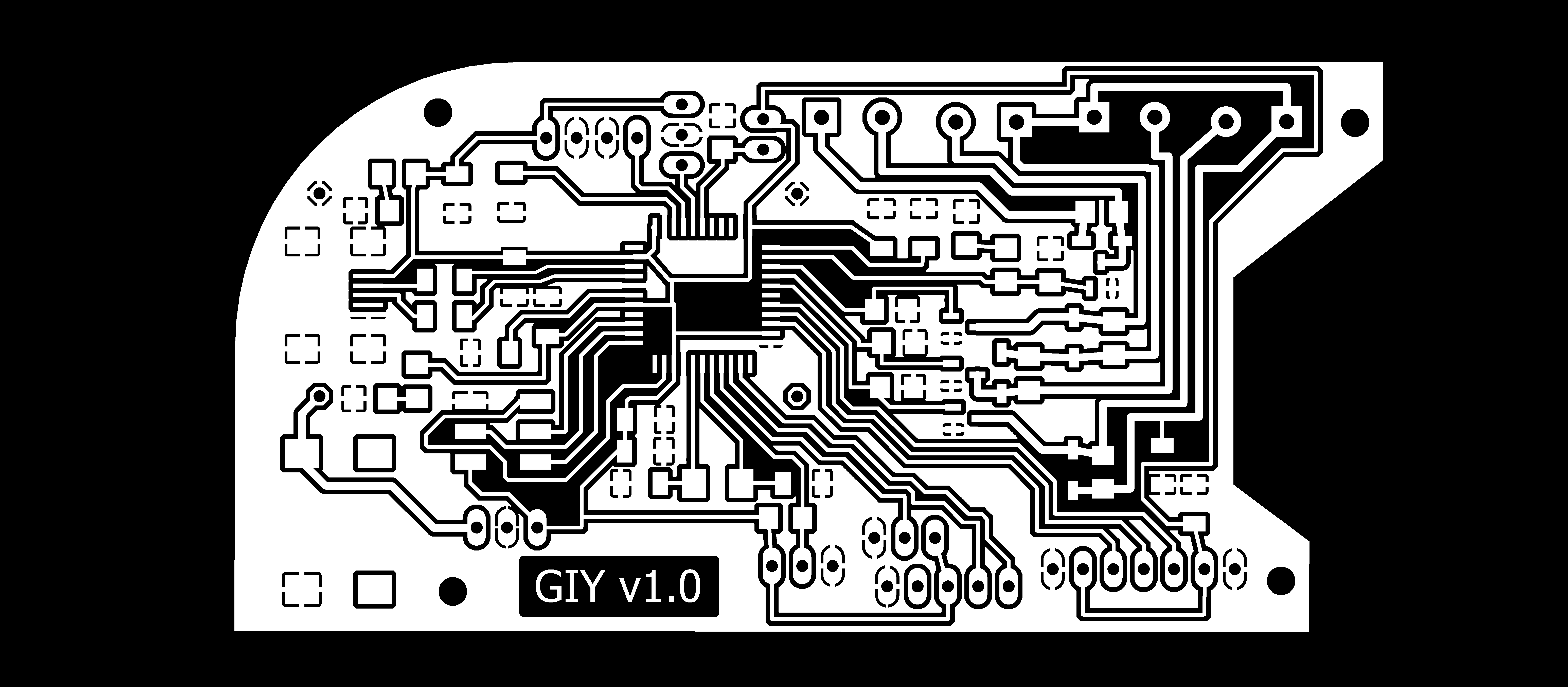
제조공정
구성품 및 소모품 Arduino UNO × 1 이 프로젝트 정보 github에서 진행 상황 보기 회로도 논리 분석기 모든 코드는 여기에 있습니다https://github.com/aster94/logic-analyzer
구성품 및 소모품 SparkFun Arduino Pro Mini 328 - 5V/16MHz × 5 5 초음파 센서 × 5 Perfboard × 5 진동 모터 × 5 부저 × 5 5mm LED:빨간색 × 5 슬라이드 스위치 × 5 암컷 헤더 8 위치 1 행(0.1) × 2 남성 헤더 40 위치 1 행(0.1) × 2 점퍼 와이어(일반) × 4