HC-05 Bluetooth, NRF24L01 및 HC-12 트랜시버 모듈을 사용하는 Arduino 로봇 자동차 무선 제어
<메인 클래스="사이트 메인" id="메인">
이 튜토리얼에서는 이전 비디오에서 만든 Arduino 로봇 자동차를 무선으로 제어하는 방법을 배웁니다. HC-05 블루투스 모듈, NRF24L01 트랜시버 모듈, HC-12 장거리 무선 모듈, 스마트폰과 맞춤형 안드로이드 애플리케이션 등 세 가지 무선 제어 방법을 보여드리겠습니다. 자세한 내용은 다음 동영상을 보거나 아래에 작성된 튜토리얼을 참조하세요.
이러한 각 모듈을 Arduino 보드에 연결하고 사용하는 방법에 대한 자습서가 이미 있으므로 자세한 내용이 필요하면 언제든지 확인할 수 있습니다. 각각에 대한 링크는 아래 기사에서 찾을 수 있습니다.
HC-05 블루투스 모듈을 사용한 Arduino 로봇 자동차 제어
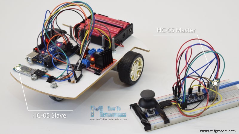
Bluetooth 통신부터 시작하겠습니다. 이를 위해 마스터 및 슬레이브 장치로 구성해야 하는 2개의 HC-05 Bluetooth 모듈이 필요합니다.
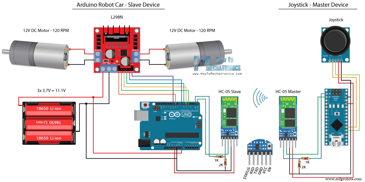
AT 명령을 사용하여 쉽게 할 수 있으며 조이스틱을 마스터로 설정하고 Arduino 로봇 자동차를 슬레이브로 설정합니다. 이 예의 전체 회로도는 다음과 같습니다.
조이스틱을 사용하여 Arduino 로봇 자동차를 직접 제어하는 이전 자습서에서 동일한 코드를 사용하고 일부 수정합니다.
HC-05 마스터 코드:
/*
   Arduino Robot Car Wireless Control using the HC-05 Bluetooth

                == MASTER DEVICE - Joystick ==

   by Dejan Nedelkovski, www.HowToMechatronics.com
*/

int xAxis, yAxis;

void setup() {
  Serial.begin(38400); // Default communication rate of the Bluetooth module
}

void loop() {
  xAxis = analogRead(A0); // Read Joysticks X-axis
  yAxis = analogRead(A1); // Read Joysticks Y-axis

  // Send the values via the serial port to the slave HC-05 Bluetooth device
  Serial.write(xAxis/4); // Dividing by 4 for converting from 0 - 1023 to 0 - 256, (1 byte) range
  Serial.write(yAxis/4);
  delay(20);
}Code language: Arduino (arduino)
마스터 장치 또는 조이스틱의 코드는 매우 간단합니다. 실제로 모터의 속도를 조절하는 조이스틱의 X 및 Y 값을 읽고 직렬 포트를 통해 슬레이브 HC-05 Bluetooth 장치로 보내면 됩니다. 여기서 우리는 0에서 1023까지의 조이스틱의 아날로그 값을 4로 다이빙하여 0에서 255까지의 값으로 변환한다는 것을 알 수 있습니다.
0에서 255까지의 범위를 Bluetooth 장치를 통해 다른 쪽이나 Arduino 로봇 자동차에서 더 쉽게 받아들일 수 있는 1바이트로 보낼 수 있기 때문에 이렇게 합니다.
따라서 여기에서 직렬이 2바이트, X 및 Y 값을 수신했다면 Serial.read() 함수를 사용하여 두 값을 모두 읽습니다.
// Code from the Arduino Robot Car

// Read the incoming data from the Joystick, or the master Bluetooth device
  while (Serial.available() >= 2) {
    x = Serial.read();
    delay(10);
    y = Serial.read();
  }Code language: Arduino (arduino)
이제 값을 0에서 1023 사이의 범위로 다시 변환하기만 하면 됩니다. 이는 이전 비디오에서 작동 방식을 이미 설명한 아래 모터 제어 코드에 적합합니다.
// Code from the Arduino Robot Car

// Convert back the 0 - 255 range to 0 - 1023, suitable for motor control code below
xAxis = x*4;
yAxis = y*4;Code language: Arduino (arduino)
코드를 업로드할 때 Arduino 보드의 RX 및 TX 핀을 분리해야 합니다.
전체 HC-05 슬레이브 코드:
/*
   Arduino Robot Car Wireless Control using the HC-05 Bluetooth

             == SLAVE DEVICE - Arduino robot car ==

   by Dejan Nedelkovski, www.HowToMechatronics.com
*/

#define enA 9
#define in1 4
#define in2 5
#define enB 10
#define in3 6
#define in4 7

int xAxis, yAxis;
unsigned int  x = 0;
unsigned int  y = 0;

int motorSpeedA = 0;
int motorSpeedB = 0;

void setup() {
  pinMode(enA, OUTPUT);
  pinMode(enB, OUTPUT);
  pinMode(in1, OUTPUT);
  pinMode(in2, OUTPUT);
  pinMode(in3, OUTPUT);
  pinMode(in4, OUTPUT);

  Serial.begin(38400); // Default communication rate of the Bluetooth module
}

void loop() {
  // Default value - no movement when the Joystick stays in the center
  x = 510 / 4;
  y = 510 / 4;

  // Read the incoming data from the Joystick, or the master Bluetooth device
  while (Serial.available() >= 2) {
    x = Serial.read();
    delay(10);
    y = Serial.read();
  }
  delay(10);
  // Convert back the 0 - 255 range to 0 - 1023, suitable for motor control code below
  xAxis = x*4;
  yAxis = y*4;

  // Y-axis used for forward and backward control
  if (yAxis < 470) {
    // Set Motor A backward
    digitalWrite(in1, HIGH);
    digitalWrite(in2, LOW);
    // Set Motor B backward
    digitalWrite(in3, HIGH);
    digitalWrite(in4, LOW);
    // Convert the declining Y-axis readings for going backward from 470 to 0 into 0 to 255 value for the PWM signal for increasing the motor speed
    motorSpeedA = map(yAxis, 470, 0, 0, 255);
    motorSpeedB = map(yAxis, 470, 0, 0, 255);
  }
  else if (yAxis > 550) {
    // Set Motor A forward
    digitalWrite(in1, LOW);
    digitalWrite(in2, HIGH);
    // Set Motor B forward
    digitalWrite(in3, LOW);
    digitalWrite(in4, HIGH);
    // Convert the increasing Y-axis readings for going forward from 550 to 1023 into 0 to 255 value for the PWM signal for increasing the motor speed
    motorSpeedA = map(yAxis, 550, 1023, 0, 255);
    motorSpeedB = map(yAxis, 550, 1023, 0, 255);
  }
  // If joystick stays in middle the motors are not moving
  else {
    motorSpeedA = 0;
    motorSpeedB = 0;
  }

  // X-axis used for left and right control
  if (xAxis < 470) {
    // Convert the declining X-axis readings from 470 to 0 into increasing 0 to 255 value
    int xMapped = map(xAxis, 470, 0, 0, 255);
    // Move to left - decrease left motor speed, increase right motor speed
    motorSpeedA = motorSpeedA - xMapped;
    motorSpeedB = motorSpeedB + xMapped;
    // Confine the range from 0 to 255
    if (motorSpeedA < 0) {
      motorSpeedA = 0;
    }
    if (motorSpeedB > 255) {
      motorSpeedB = 255;
    }
  }
  if (xAxis > 550) {
    // Convert the increasing X-axis readings from 550 to 1023 into 0 to 255 value
    int xMapped = map(xAxis, 550, 1023, 0, 255);
    // Move right - decrease right motor speed, increase left motor speed
    motorSpeedA = motorSpeedA + xMapped;
    motorSpeedB = motorSpeedB - xMapped;
    // Confine the range from 0 to 255
    if (motorSpeedA > 255) {
      motorSpeedA = 255;
    }
    if (motorSpeedB < 0) {
      motorSpeedB = 0;
    }
  }
  // Prevent buzzing at low speeds (Adjust according to your motors. My motors couldn't start moving if PWM value was below value of 70)
  if (motorSpeedA < 70) {
    motorSpeedA = 0;
  }
  if (motorSpeedB < 70) {
    motorSpeedB = 0;
  }
  analogWrite(enA, motorSpeedA); // Send PWM signal to motor A
  analogWrite(enB, motorSpeedB); // Send PWM signal to motor B
}Code language: Arduino (arduino)
스마트폰과 맞춤형 Android 앱을 사용한 Arduino 로봇 자동차 제어
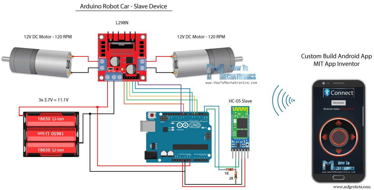
다음으로 맞춤형 Android 앱을 사용하여 Arduino 로봇 자동차를 제어하는 방법을 살펴보겠습니다. 로봇 자동차의 회로도는 HC-05 블루투스 모드가 슬레이브 장치로 설정된 이전 예와 완전히 동일합니다.
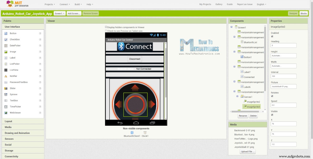
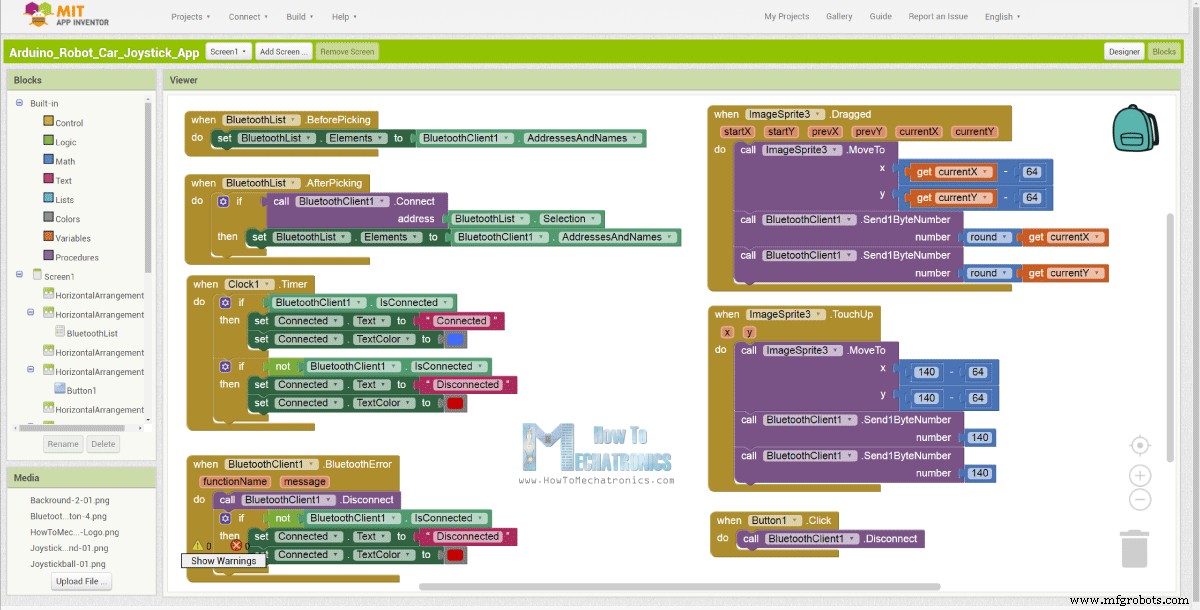
반면에 MIT App Inventor 온라인 애플리케이션을 사용하여 자체 Android 앱을 빌드하고 다음과 같이 표시합니다.
따라서 기본적으로 앱은 두 개의 이미지 또는 이미지 스프라이트로 구성된 조이스틱을 시뮬레이션합니다.
이 앱의 블록을 살펴보면 조이스틱 스프라이트를 드래그하면 조이스틱 볼의 이미지가 손가락의 현재 위치로 이동함과 동시에 X와 Y를 보내는 것을 볼 수 있습니다. 블루투스를 통해 값을 Arduino 자동차로 전송합니다.
이 값은 이전 예제와 동일한 방식으로 Serial.read 함수를 사용하여 Arduino에서 허용됩니다.
// Read the incoming data from the Smartphone Android App
  while (Serial.available() >= 2) {
    x = Serial.read();
    delay(10);
    y = Serial.read();
  }Code language: Arduino (arduino)
여기서 추가적으로 해야 할 일은 스마트폰에서 수신한 X, Y 값을 아래의 모터 제어 코드에 적합한 0~1023 범위로 변환하는 것입니다. 이 값은 캔버스 크기에 따라 달라지며, 내 앱에서 얻은 X 및 Y 값은 60에서 220 사이였으며 map() 함수를 사용하여 쉽게 변환했습니다.
// Makes sure we receive corrent values
  if (x > 60 & x < 220) {
    xAxis = map(x, 220, 60, 1023, 0); // Convert the smartphone X and Y values to 0 - 1023 range, suitable motor for the motor control code below
  }
  if (y > 60 & y < 220) {
    yAxis = map(y, 220, 60, 0, 1023);
  }Code language: Arduino (arduino)
응용 프로그램 블록에서 이미지 스프라이트를 터치하면 조이스틱 볼이 캔버스 중앙으로 다시 이동하고 이동을 중지하기 위해 적절한 값이 자동차로 전송되는 것을 볼 수 있습니다. 웹사이트 기사에서 이 앱을 찾아 다운로드할 수 있을 뿐만 아니라 조이스틱의 두 이미지를 찾아 다운로드할 수 있으므로 직접 만들거나 이 앱을 수정할 수 있습니다.
아래에서 Android 앱과 조이스틱용 이미지 두 개를 다운로드할 수 있습니다.
Arduino_Robot_Car_Joystick_App.apk
파일 1개 1.62MB 다운로드
Arduino_Robot_Car_Joystick_App_aia_file
파일 1개 171.20KB 다운로드
조이스틱 앱 이미지
파일 1개 44.36KB 다운로드
Arduino 코드 완성:
/*
   Arduino Robot Car Wireless Control using the HC-05 Bluetooth and custom-build Android app

             == SLAVE DEVICE - Arduino robot car ==

   by Dejan Nedelkovski, www.HowToMechatronics.com
*/

#define enA 9
#define in1 4
#define in2 5
#define enB 10
#define in3 6
#define in4 7

int xAxis, yAxis;
int  x = 0;
int  y = 0;

int motorSpeedA = 0;
int motorSpeedB = 0;

void setup() {
  pinMode(enA, OUTPUT);
  pinMode(enB, OUTPUT);
  pinMode(in1, OUTPUT);
  pinMode(in2, OUTPUT);
  pinMode(in3, OUTPUT);
  pinMode(in4, OUTPUT);

  Serial.begin(38400); // Default communication rate of the Bluetooth module
}

void loop() {
  // Default value - no movement when the Joystick stays in the center
  xAxis = 510;
  yAxis = 510;

  // Read the incoming data from the Smartphone Android App
  while (Serial.available() >= 2) {
    x = Serial.read();
    delay(10);
    y = Serial.read();
  }
  delay(10);

  // Makes sure we receive corrent values
  if (x > 60 & x < 220) {
    xAxis = map(x, 220, 60, 1023, 0); // Convert the smartphone X and Y values to 0 - 1023 range, suitable motor for the motor control code below
  }
  if (y > 60 & y < 220) {
    yAxis = map(y, 220, 60, 0, 1023);
  }

  // Y-axis used for forward and backward control
  if (yAxis < 470) {
    // Set Motor A backward
    digitalWrite(in1, HIGH);
    digitalWrite(in2, LOW);
    // Set Motor B backward
    digitalWrite(in3, HIGH);
    digitalWrite(in4, LOW);
    // Convert the declining Y-axis readings for going backward from 470 to 0 into 0 to 255 value for the PWM signal for increasing the motor speed
    motorSpeedA = map(yAxis, 470, 0, 0, 255);
    motorSpeedB = map(yAxis, 470, 0, 0, 255);
  }
  else if (yAxis > 550) {
    // Set Motor A forward
    digitalWrite(in1, LOW);
    digitalWrite(in2, HIGH);
    // Set Motor B forward
    digitalWrite(in3, LOW);
    digitalWrite(in4, HIGH);
    // Convert the increasing Y-axis readings for going forward from 550 to 1023 into 0 to 255 value for the PWM signal for increasing the motor speed
    motorSpeedA = map(yAxis, 550, 1023, 0, 255);
    motorSpeedB = map(yAxis, 550, 1023, 0, 255);
  }
  // If joystick stays in middle the motors are not moving
  else {
    motorSpeedA = 0;
    motorSpeedB = 0;
  }

  // X-axis used for left and right control
  if (xAxis < 470) {
    // Convert the declining X-axis readings from 470 to 0 into increasing 0 to 255 value
    int xMapped = map(xAxis, 470, 0, 0, 255);
    // Move to left - decrease left motor speed, increase right motor speed
    motorSpeedA = motorSpeedA - xMapped;
    motorSpeedB = motorSpeedB + xMapped;
    // Confine the range from 0 to 255
    if (motorSpeedA < 0) {
      motorSpeedA = 0;
    }
    if (motorSpeedB > 255) {
      motorSpeedB = 255;
    }
  }
  if (xAxis > 550) {
    // Convert the increasing X-axis readings from 550 to 1023 into 0 to 255 value
    int xMapped = map(xAxis, 550, 1023, 0, 255);
    // Move right - decrease right motor speed, increase left motor speed
    motorSpeedA = motorSpeedA + xMapped;
    motorSpeedB = motorSpeedB - xMapped;
    // Confine the range from 0 to 255
    if (motorSpeedA > 255) {
      motorSpeedA = 255;
    }
    if (motorSpeedB < 0) {
      motorSpeedB = 0;
    }
  }
  // Prevent buzzing at low speeds (Adjust according to your motors. My motors couldn't start moving if PWM value was below value of 70)
  if (motorSpeedA < 70) {
    motorSpeedA = 0;
  }
  if (motorSpeedB < 70) {
    motorSpeedB = 0;
  }
  analogWrite(enA, motorSpeedA); // Send PWM signal to motor A
  analogWrite(enB, motorSpeedB); // Send PWM signal to motor B
}Code language: Arduino (arduino)
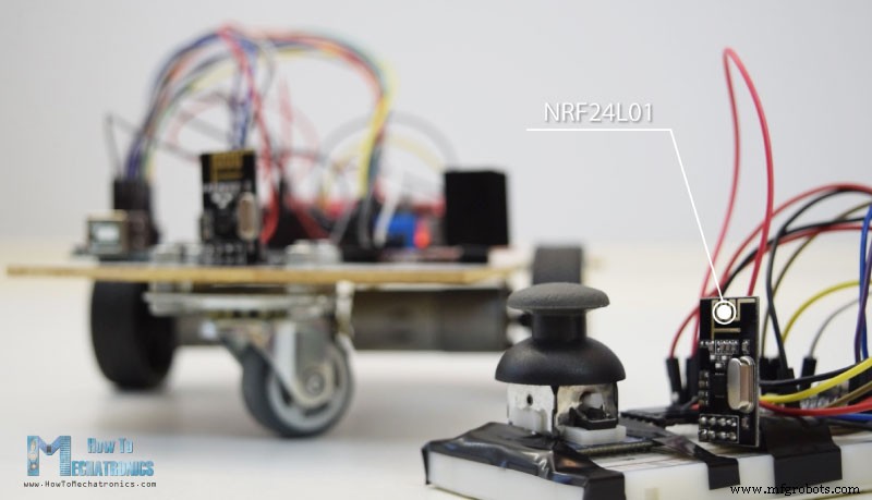
NRF24L01 트랜시버 모듈을 사용한 Arduino 로봇 자동차 무선 제어
이제 다음 방법인 NRF24L01 트랜시버 모듈을 사용하여 Arduino 로봇 자동차의 무선 제어로 넘어갈 수 있습니다.
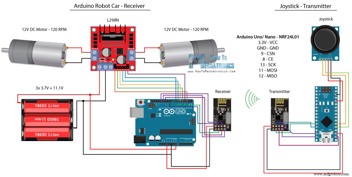
다음은 회로도입니다. 이 모듈은 SPI 통신을 사용하므로 이전 예와 비교하여 L298N 드라이버의 Enable A 및 Enable B 핀을 Arduino 보드의 핀 번호 2와 3으로 이동했습니다. NRF24L01을 얻을 수 있습니다. 다음 Amazon 링크의 모듈.
소스 코드
이 예에서는 RF24 라이브러리를 설치해야 합니다. 앞의 예와 비슷하게 핀을 정의하고 모듈을 트랜스미터로 설정한 후 조이스틱의 X, Y 값을 읽어 아두이노 로봇카의 다른 NRF24L01 모듈로 보낸다.
먼저 아날로그 판독값은 string.toCharArray() 함수를 사용하여 문자 배열에 넣는 문자열이라는 것을 알 수 있습니다. 그런 다음 radio.write() 함수를 사용하여 해당 문자 배열 데이터를 다른 모듈로 보냅니다.
송신기 코드:
/*
   Arduino Robot Car Wireless Control using the NRF24L01 Transceiver module

             == Transmitter - Joystick ==

   by Dejan Nedelkovski, www.HowToMechatronics.com

   Library: TMRh20/RF24, https://github.com/tmrh20/RF24/
*/

#include <SPI.h>
#include <nRF24L01.h>
#include <RF24.h>

RF24 radio(8, 9); // CE, CSN
const byte address[6] = "00001";

char xyData[32] = "";
String xAxis, yAxis;

void setup() {
  Serial.begin(9600);
  radio.begin();
  radio.openWritingPipe(address);
  radio.setPALevel(RF24_PA_MIN);
  radio.stopListening();
}

void loop() {

  xAxis = analogRead(A0); // Read Joysticks X-axis
  yAxis = analogRead(A1); // Read Joysticks Y-axis
  // X value
  xAxis.toCharArray(xyData, 5); // Put the String (X Value) into a character array
  radio.write(&xyData, sizeof(xyData)); // Send the array data (X value) to the other NRF24L01 modile
  // Y value
  yAxis.toCharArray(xyData, 5);
  radio.write(&xyData, sizeof(xyData));
  delay(20);
}Code language: Arduino (arduino)
다른 쪽에서. Arduino 로봇 자동차에서는 모듈을 수신기로 정의한 후 radio.read() 함수를 사용하여 데이터를 받습니다. 그런 다음 atoi() 함수를 사용하여 수신된 데이터 또는 조이스틱의 X 및 Y 값을 아래 모터 제어 코드에 적합한 정수 값으로 변환합니다.
// Code from the Arduino Robot Car - NRF24L01 example

if (radio.available()) {   // If the NRF240L01 module received data
    radio.read(&receivedData, sizeof(receivedData)); // Read the data and put it into character array
    xAxis = atoi(&receivedData[0]); // Convert the data from the character array (received X value) into integer
    delay(10);
    radio.read(&receivedData, sizeof(receivedData));
    yAxis = atoi(&receivedData[0]);
    delay(10);
  }Code language: Arduino (arduino)
너무 간단하지만 물론 내가 이미 말했듯이 모듈을 연결하고 설정하는 방법에 대한 자세한 내용이 필요하면 언제든지 내 특정 자습서에서 확인할 수 있습니다.
수신자 코드:
/*
   Arduino Robot Car Wireless Control using the NRF24L01 Transceiver module

             == Receiver - Arduino robot car ==

   by Dejan Nedelkovski, www.HowToMechatronics.com

   Library: TMRh20/RF24, https://github.com/tmrh20/RF24/
*/
#include <SPI.h>
#include <nRF24L01.h>
#include <RF24.h>

#define enA 2   // Note: Pin 9 in previous video ( pin 10 is used for the SPI communication of the NRF24L01)
#define in1 4
#define in2 5
#define enB 3   // Note:  Pin 10 in previous video
#define in3 6
#define in4 7

RF24 radio(8, 9); // CE, CSN
const byte address[6] = "00001";

char receivedData[32] = "";
int  xAxis, yAxis;

int motorSpeedA = 0;
int motorSpeedB = 0;

void setup() {
  pinMode(enA, OUTPUT);
  pinMode(enB, OUTPUT);
  pinMode(in1, OUTPUT);
  pinMode(in2, OUTPUT);
  pinMode(in3, OUTPUT);
  pinMode(in4, OUTPUT);
  Serial.begin(9600);
  radio.begin();
  radio.openReadingPipe(0, address);
  radio.setPALevel(RF24_PA_MIN);
  radio.startListening();
}

void loop() {

  if (radio.available()) {   // If the NRF240L01 module received data
    radio.read(&receivedData, sizeof(receivedData)); // Read the data and put it into character array
    xAxis = atoi(&receivedData[0]); // Convert the data from the character array (received X value) into integer
    delay(10);
    radio.read(&receivedData, sizeof(receivedData));
    yAxis = atoi(&receivedData[0]);
    delay(10);
  }

  // Y-axis used for forward and backward control
  if (yAxis < 470) {
    // Set Motor A backward
    digitalWrite(in1, HIGH);
    digitalWrite(in2, LOW);
    // Set Motor B backward
    digitalWrite(in3, HIGH);
    digitalWrite(in4, LOW);
    // Convert the declining Y-axis readings for going backward from 470 to 0 into 0 to 255 value for the PWM signal for increasing the motor speed
    motorSpeedA = map(yAxis, 470, 0, 0, 255);
    motorSpeedB = map(yAxis, 470, 0, 0, 255);
  }
  else if (yAxis > 550) {
    // Set Motor A forward
    digitalWrite(in1, LOW);
    digitalWrite(in2, HIGH);
    // Set Motor B forward
    digitalWrite(in3, LOW);
    digitalWrite(in4, HIGH);
    // Convert the increasing Y-axis readings for going forward from 550 to 1023 into 0 to 255 value for the PWM signal for increasing the motor speed
    motorSpeedA = map(yAxis, 550, 1023, 0, 255);
    motorSpeedB = map(yAxis, 550, 1023, 0, 255);
  }
  // If joystick stays in middle the motors are not moving
  else {
    motorSpeedA = 0;
    motorSpeedB = 0;
  }

  // X-axis used for left and right control
  if (xAxis < 470) {
    // Convert the declining X-axis readings from 470 to 0 into increasing 0 to 255 value
    int xMapped = map(xAxis, 470, 0, 0, 255);
    // Move to left - decrease left motor speed, increase right motor speed
    motorSpeedA = motorSpeedA - xMapped;
    motorSpeedB = motorSpeedB + xMapped;
    // Confine the range from 0 to 255
    if (motorSpeedA < 0) {
      motorSpeedA = 0;
    }
    if (motorSpeedB > 255) {
      motorSpeedB = 255;
    }
  }
  if (xAxis > 550) {
    // Convert the increasing X-axis readings from 550 to 1023 into 0 to 255 value
    int xMapped = map(xAxis, 550, 1023, 0, 255);
    // Move right - decrease right motor speed, increase left motor speed
    motorSpeedA = motorSpeedA + xMapped;
    motorSpeedB = motorSpeedB - xMapped;
    // Confine the range from 0 to 255
    if (motorSpeedA > 255) {
      motorSpeedA = 255;
    }
    if (motorSpeedB < 0) {
      motorSpeedB = 0;
    }
  }
  // Prevent buzzing at low speeds (Adjust according to your motors. My motors couldn't start moving if PWM value was below value of 70)
  if (motorSpeedA < 70) {
    motorSpeedA = 0;
  }
  if (motorSpeedB < 70) {
    motorSpeedB = 0;
  }
  analogWrite(enA, motorSpeedA); // Send PWM signal to motor A
  analogWrite(enB, motorSpeedB); // Send PWM signal to motor B
}Code language: Arduino (arduino)
HC-12 장거리 트랜시버를 사용한 Arduino 로봇 자동차 무선 제어
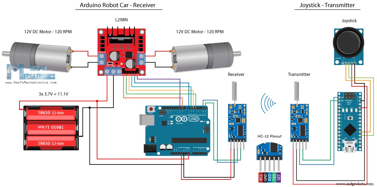
Arduino 로봇 자동차의 마지막 무선 제어 방법으로 HC-12 장거리 송수신기 모듈을 사용합니다. 이 모듈은 최대 1.8km의 거리에서 서로 통신할 수 있습니다.
이 예제의 회로도는 HC-05 Bluetooth 모듈의 경우와 거의 동일합니다. 직렬 포트를 통해 Arduino와 통신하는 데 동일한 방법을 사용하기 때문입니다.
<그림 클래스="aligncenter">
다음 Amazon 링크에서 HC-12 트랜시버 모듈을 다운로드할 수 있습니다.
소스 코드
조이스틱 코드는 블루투스 통신용 코드와 동일합니다. 조이스틱의 아날로그 값을 읽고 Serial.write() 함수를 사용하여 다른 모듈로 보냅니다.
송신기 코드:
/*
   Arduino Robot Car Wireless Control using the HC-12 long range wireless module

                == Transmitter - Joystick ==

   by Dejan Nedelkovski, www.HowToMechatronics.com
*/

int xAxis, yAxis;

void setup() {
  Serial.begin(9600); // Default communication rate of the Bluetooth module
}

void loop() {
  xAxis = analogRead(A0); // Read Joysticks X-axis
  yAxis = analogRead(A1); // Read Joysticks Y-axis

  // Send the values via the serial port to the slave HC-05 Bluetooth device
  Serial.write(xAxis/4); // Dividing by 4 for converting from 0 - 1023 to 0 - 256, (1 byte) range
  Serial.write(yAxis/4);
  delay(20);
}Code language: Arduino (arduino)
반면에 while() 루프를 사용하여 데이터가 도착할 때까지 기다린 다음 Serial.read() 함수를 사용하여 데이터를 읽고 아래의 모터 제어 코드에 적합한 0에서 1023 범위로 다시 변환합니다.
수신기 코드:
/*
   Arduino Robot Car Wireless Control using the HC-12 long range wireless module

             == Receiver - Arduino robot car ==

   by Dejan Nedelkovski, www.HowToMechatronics.com
*/

#define enA 9
#define in1 4
#define in2 5
#define enB 10
#define in3 6
#define in4 7

int xAxis, yAxis;
int  x = 0;
int  y = 0;

int motorSpeedA = 0;
int motorSpeedB = 0;

void setup() {
  pinMode(enA, OUTPUT);
  pinMode(enB, OUTPUT);
  pinMode(in1, OUTPUT);
  pinMode(in2, OUTPUT);
  pinMode(in3, OUTPUT);
  pinMode(in4, OUTPUT);

  Serial.begin(9600); // Default communication rate of the Bluetooth module
}

void loop() {
  // Default value - no movement when the Joystick stays in the center
  xAxis = 510;
  yAxis = 510;

  // Read the incoming data from the
  while (Serial.available() == 0) {}
  x = Serial.read();
  delay(10);
  y = Serial.read();
  delay(10);

  // Convert back the 0 - 255 range to 0 - 1023, suitable for motor control code below
  xAxis = x * 4;
  yAxis = y * 4;

  // Y-axis used for forward and backward control
  if (yAxis < 470) {
    // Set Motor A backward
    digitalWrite(in1, HIGH);
    digitalWrite(in2, LOW);
    // Set Motor B backward
    digitalWrite(in3, HIGH);
    digitalWrite(in4, LOW);
    // Convert the declining Y-axis readings for going backward from 470 to 0 into 0 to 255 value for the PWM signal for increasing the motor speed
    motorSpeedA = map(yAxis, 470, 0, 0, 255);
    motorSpeedB = map(yAxis, 470, 0, 0, 255);
  }
  else if (yAxis > 550) {
    // Set Motor A forward
    digitalWrite(in1, LOW);
    digitalWrite(in2, HIGH);
    // Set Motor B forward
    digitalWrite(in3, LOW);
    digitalWrite(in4, HIGH);
    // Convert the increasing Y-axis readings for going forward from 550 to 1023 into 0 to 255 value for the PWM signal for increasing the motor speed
    motorSpeedA = map(yAxis, 550, 1023, 0, 255);
    motorSpeedB = map(yAxis, 550, 1023, 0, 255);
  }
  // If joystick stays in middle the motors are not moving
  else {
    motorSpeedA = 0;
    motorSpeedB = 0;
  }

  // X-axis used for left and right control
  if (xAxis < 470) {
    // Convert the declining X-axis readings from 470 to 0 into increasing 0 to 255 value
    int xMapped = map(xAxis, 470, 0, 0, 255);
    // Move to left - decrease left motor speed, increase right motor speed
    motorSpeedA = motorSpeedA - xMapped;
    motorSpeedB = motorSpeedB + xMapped;
    // Confine the range from 0 to 255
    if (motorSpeedA < 0) {
      motorSpeedA = 0;
    }
    if (motorSpeedB > 255) {
      motorSpeedB = 255;
    }
  }
  if (xAxis > 550) {
    // Convert the increasing X-axis readings from 550 to 1023 into 0 to 255 value
    int xMapped = map(xAxis, 550, 1023, 0, 255);
    // Move right - decrease right motor speed, increase left motor speed
    motorSpeedA = motorSpeedA + xMapped;
    motorSpeedB = motorSpeedB - xMapped;
    // Confine the range from 0 to 255
    if (motorSpeedA > 255) {
      motorSpeedA = 255;
    }
    if (motorSpeedB < 0) {
      motorSpeedB = 0;
    }
  }
  // Prevent buzzing at low speeds (Adjust according to your motors. My motors couldn't start moving if PWM value was below value of 70)
  if (motorSpeedA < 70) {
    motorSpeedA = 0;
  }
  if (motorSpeedB < 70) {
    motorSpeedB = 0;
  }
  analogWrite(enA, motorSpeedA); // Send PWM signal to motor A
  analogWrite(enB, motorSpeedB); // Send PWM signal to motor B
}Code language: Arduino (arduino)