

제조공정

산업 제조
<메인 클래스="사이트 메인" id="메인">
이 Arduino Tutorial에서는 Arduino와 TCS230 / TCS3200 컬러 센서를 사용하여 색상을 감지하는 방법을 배웁니다. 자세한 내용은 다음 동영상을 보거나 아래에 작성된 튜토리얼을 참조하세요.
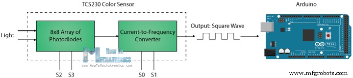
TCS230은 8 x 8 포토다이오드 어레이의 도움으로 색광을 감지합니다. 그런 다음 전류-주파수 변환기를 사용하여 포토다이오드의 판독값이 광도에 정비례하는 주파수를 갖는 구형파로 변환됩니다. 마지막으로 Arduino 보드를 사용하여 구형파 출력을 읽고 색상에 대한 결과를 얻을 수 있습니다.
센서를 자세히 살펴보면 다양한 색상을 감지하는 방법을 알 수 있습니다. 포토다이오드에는 세 가지 색상 필터가 있습니다. 그 중 16개에는 빨간색 필터가 있고, 다른 16개에는 녹색 필터가 있고, 다른 16개에는 파란색 필터가 있으며, 나머지 16개 포토다이오드에는 필터가 없는 투명합니다.
<그림 클래스="aligncenter">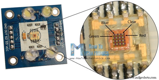
각 16개의 포토다이오드는 병렬로 연결되어 있으므로 2개의 제어 핀 S2와 S3을 사용하여 어느 것을 읽을 것인지 선택할 수 있습니다. 예를 들어 빨간색을 감지하려면 표에 따라 2개의 핀을 낮은 논리 레벨로 설정하여 16개의 빨간색 필터링된 포토다이오드를 사용할 수 있습니다.
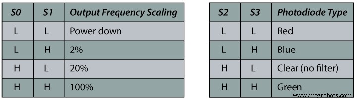
센서에는 출력 주파수를 조정하는 데 사용되는 두 개의 제어 핀 S0 및 S1이 더 있습니다. 주파수는 100%, 20% 또는 2%의 세 가지 사전 설정 값으로 조정될 수 있습니다. 이 주파수 스케일링 기능을 통해 센서의 출력을 다양한 주파수 카운터 또는 마이크로컨트롤러에 최적화할 수 있습니다.
이제 TCS230 센서를 Arduino 보드에 연결할 준비가 되었습니다. 다음은 회로도입니다.
<그림 클래스="aligncenter">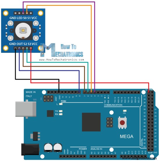
아래 링크에서 이 Arduino 튜토리얼에 필요한 구성요소를 얻을 수 있습니다.
설명: 먼저 센서가 연결된 핀을 정의하고 주파수를 읽기 위한 변수를 정의해야 합니다. 설정 섹션에서 4개의 제어 핀을 출력으로 정의하고 센서 출력을 Arduino 입력으로 정의해야 합니다. 여기에서 주파수 스케일링도 설정해야 합니다. 이 예에서는 20%로 설정하고 직렬 통신을 시작하여 결과를 직렬 모니터에 표시합니다.
루프 섹션에서는 빨간색 필터링된 포토다이오드를 읽는 것으로 시작합니다. 이를 위해 2개의 제어 핀 S2 및 S3을 낮은 논리 레벨로 설정합니다. 그런 다음 "pulseIn()" 함수를 사용하여 출력 주파수를 읽고 변수 "주파수"에 넣습니다. Serial.print() 함수를 사용하여 직렬 모니터에 결과를 인쇄합니다. 다른 두 색상에도 동일한 절차가 적용되며 적절한 색상에 대해 제어 핀을 조정하기만 하면 됩니다.
/*     Arduino Color Sensing Tutorial
 *
 *  by Dejan Nedelkovski, www.HowToMechatronics.com
 *
 */

#define S0 4
#define S1 5
#define S2 6
#define S3 7
#define sensorOut 8

int frequency = 0;

void setup() {
  pinMode(S0, OUTPUT);
  pinMode(S1, OUTPUT);
  pinMode(S2, OUTPUT);
  pinMode(S3, OUTPUT);
  pinMode(sensorOut, INPUT);

  // Setting frequency-scaling to 20%
  digitalWrite(S0,HIGH);
  digitalWrite(S1,LOW);

  Serial.begin(9600);
}

void loop() {
  // Setting red filtered photodiodes to be read
  digitalWrite(S2,LOW);
  digitalWrite(S3,LOW);
  // Reading the output frequency
  frequency = pulseIn(sensorOut, LOW);
  // Printing the value on the serial monitor
  Serial.print("R= ");//printing name
  Serial.print(frequency);//printing RED color frequency
  Serial.print("  ");
  delay(100);

  // Setting Green filtered photodiodes to be read
  digitalWrite(S2,HIGH);
  digitalWrite(S3,HIGH);
  // Reading the output frequency
  frequency = pulseIn(sensorOut, LOW);
  // Printing the value on the serial monitor
  Serial.print("G= ");//printing name
  Serial.print(frequency);//printing RED color frequency
  Serial.print("  ");
  delay(100);

  // Setting Blue filtered photodiodes to be read
  digitalWrite(S2,LOW);
  digitalWrite(S3,HIGH);
  // Reading the output frequency
  frequency = pulseIn(sensorOut, LOW);
  // Printing the value on the serial monitor
  Serial.print("B= ");//printing name
  Serial.print(frequency);//printing RED color frequency
  Serial.println("  ");
  delay(100);
}Code language: Arduino (arduino)
이제 직렬 모니터를 실행하면 일부 값을 얻기 시작할 것입니다. 이 값은 선택한 주파수 스케일링과 주변 조명에 따라 달라집니다.
<그림 클래스="aligncenter">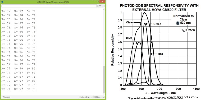
센서 데이터시트의 포토다이오드 스펙트럼 응답도에서 볼 수 있듯이 각 포토다이오드 유형의 감도가 다르기 때문에 세 가지 값이 다릅니다.
그럼에도 불구하고 이제 센서 앞에 다른 색상을 가져올 때 값이 어떻게 반응하는지 봅시다. 예를 들어 빨간색을 가져오면 초기 값이 내 경우에는 약 70에서 약 25로 떨어집니다.
<그림 클래스="aligncenter">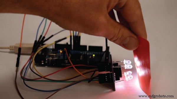
이제 감지된 색상을 0에서 255 사이의 값을 갖는 RGB 모델로 나타내려면 map() 함수를 사용하여 판독값을 0에서 255 사이의 값으로 매핑하거나 변환합니다.
//Remaping the value of the frequency to the RGB Model of 0 to 255
  frequency = map(frequency, 25,70,255,0);
70의 값은 0에 매핑되고 25의 값은 255에 매핑됩니다. 다른 두 색상에도 동일한 절차가 적용됩니다.
이 예제의 최종 소스 코드는 다음과 같습니다.
/*     Arduino Color Sensing Tutorial
 *
 *  by Dejan Nedelkovski, www.HowToMechatronics.com
 *
 */

#define S0 4
#define S1 5
#define S2 6
#define S3 7
#define sensorOut 8

int frequency = 0;

void setup() {
  pinMode(S0, OUTPUT);
  pinMode(S1, OUTPUT);
  pinMode(S2, OUTPUT);
  pinMode(S3, OUTPUT);
  pinMode(sensorOut, INPUT);

  // Setting frequency-scaling to 20%
  digitalWrite(S0,HIGH);
  digitalWrite(S1,LOW);

  Serial.begin(9600);
}

void loop() {
  // Setting red filtered photodiodes to be read
  digitalWrite(S2,LOW);
  digitalWrite(S3,LOW);
  // Reading the output frequency
  frequency = pulseIn(sensorOut, LOW);
  //Remaping the value of the frequency to the RGB Model of 0 to 255
  frequency = map(frequency, 25,72,255,0);
  // Printing the value on the serial monitor
  Serial.print("R= ");//printing name
  Serial.print(frequency);//printing RED color frequency
  Serial.print("  ");
  delay(100);

  // Setting Green filtered photodiodes to be read
  digitalWrite(S2,HIGH);
  digitalWrite(S3,HIGH);
  // Reading the output frequency
  frequency = pulseIn(sensorOut, LOW);
  //Remaping the value of the frequency to the RGB Model of 0 to 255
  frequency = map(frequency, 30,90,255,0);
  // Printing the value on the serial monitor
  Serial.print("G= ");//printing name
  Serial.print(frequency);//printing RED color frequency
  Serial.print("  ");
  delay(100);

  // Setting Blue filtered photodiodes to be read
  digitalWrite(S2,LOW);
  digitalWrite(S3,HIGH);
  // Reading the output frequency
  frequency = pulseIn(sensorOut, LOW);
  //Remaping the value of the frequency to the RGB Model of 0 to 255
  frequency = map(frequency, 25,70,255,0);
  // Printing the value on the serial monitor
  Serial.print("B= ");//printing name
  Serial.print(frequency);//printing RED color frequency
  Serial.println("  ");
  delay(100);
}Code language: Arduino (arduino)
색상은 그다지 정확하지 않지만 간단한 프로젝트에는 여전히 충분합니다. 다음 비디오에서 TCS230 컬러 센서의 또 다른 예로 Arduino 자동 색상 정렬 기계를 만드는 방법을 배울 것입니다.
<그림 클래스="aligncenter">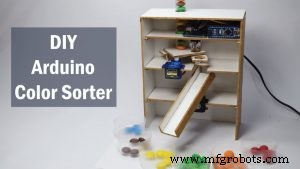
아래 댓글 섹션에서 언제든지 질문을 하고 내 Arduino 프로젝트 컬렉션을 확인하는 것을 잊지 마세요.
제조공정
Arduino 자습서 시리즈의 네 번째 Arduino 자습서에 오신 것을 환영합니다. 이 튜토리얼에서는 PWM(Pulse Width Modulation)을 사용하여 DC 및 서보 모터를 제어하는 방법을 배웁니다. 이것은 따라하기 쉬운 단계별 비디오 자습서입니다. 또한 동영상 아래에서 이 튜토리얼에 필요한 부품과 동영상의 예제 소스 코드를 찾을 수 있습니다. 첫 번째 예에 필요한 구성요소 DC 모터 ........................................................... 또는 CPU 팬
이 기사에서는 Arduino 색상 분류기를 만드는 방법을 보여 드리겠습니다. 다음 동영상을 보거나 아래에 작성된 기사를 읽을 수 있습니다. 디자인 이 Arduino 프로젝트에 필요한 것은 컬러 센서(TCS3200) 1개와 취미용 서보 모터 2개뿐입니다. 이 덕분에 이 프로젝트는 매우 간단하지만 구축하는 것은 매우 재미있습니다. 먼저 Solidworks 3D 모델링 소프트웨어를 사용하여 색상 분류기의 디자인을 만들었고 작동 원리는 다음과 같습니다. 초기에는 충전기에 고정되어 있는 컬러 주걱이 상단 서보 모터에 부착된 플랫폼으