

3D 프린팅

산업 제조
모든 FFF 3D 프린터의 기본 구성 요소 중 하나는 모터입니다. 그들은 프린트 헤드를 배치하는 데 필요한 움직임을 만들고 압출기에서 필라멘트를 당기는 일을 담당합니다.
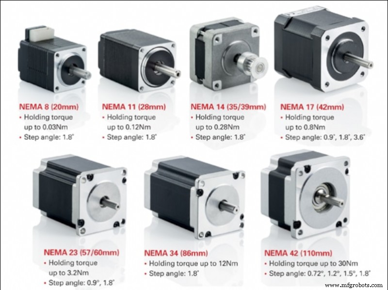
사용된 모터는 스테퍼 모터이며 가장 일반적인 유형은 NEMA 17 및 NEMA 23입니다.
좋은 품질의 스테퍼 모터는 신뢰성이 매우 높기 때문에 모터 고장의 주요 원인은 일반적으로 전원 드라이버 또는 연결과 관련된 외부에 있습니다.
스테퍼 모터는 연속적으로 회전하는 모터의 일종입니다. 회전은 주어진 각도의 불연속 점프에서 발생합니다. 표준 DC 모터와 서보 모터의 중간에 있는 모터입니다. DC 모터와 마찬가지로 여러 번의 360° 회전이 가능하며 서보 모터와 같은 정밀한 각도 위치 지정이 가능합니다.
3D 프린터에서 가장 일반적으로 사용되는 것은 일반적으로 NEMA17 또는 NEMA23 형식의 바이폴라 하이브리드 스테퍼 모터입니다. 하이브리드 모터는 VR 모터의 작은 스테퍼 기능과 영구 자석 모터의 높은 관성 기능을 결합합니다. 반면 바이폴라 모터는 유니폴라 모터보다 더 높은 토크와 앵커리지를 제공하는 동시에 무게와 크기가 더 작지만 특정 전원 컨트롤러가 필요합니다.
스테퍼 모터를 선택할 때 다음과 같은 주요 특성을 알아야 합니다.
예를 들어 XY축의 경우와 같이 이동 중에 고속을 사용하고 높은 관성을 견딜 수 있는 모터를 찾고 있다면 1.8º 단계와 높은 토크를 가진 모터를 선택해야 합니다.
Z축 모터는 높은 작업 속도가 필요하지 않으므로 0.9º 모터는 더 부드러운 움직임을 제공합니다. 이 경우 플랫폼 또는 갠트리의 무게를 지탱할 수 있도록 최대 고정 및 고정 토크가 있는 모터를 선택해야 합니다(프린터 설계에 따라 다름).
스테퍼 모터를 올바르게 연결할 때 와이어의 위치가 모델마다 다르기 때문에 제조업체의 사양 시트를 사용하는 것이 유용합니다.
일반적으로 바이폴라 스테퍼 모터에는 두 개의 독립적인 전원 공급 회로로 구성된 4개의 연결이 있습니다. 각 회로는 모터의 각 코일에 전원을 공급하는 양극과 음극으로 구성됩니다.
가장 먼저 알아야 할 것은 프린터 제어 보드에서 이 네 개의 연결 위치입니다. 제어 보드에는 두 가지 유형의 명명법이 있습니다. 첫 번째는 1A 1B 2A 2B이며 각 숫자는 회로를 나타내고 문자 A와 B는 극을 나타냅니다. 두 번째는 A A - B B - 여기서 각 문자는 회로를 나타내고 악센트는 음극을 나타냅니다.
보드의 연결이 결정되면 모터에 대해서도 동일한 작업을 수행해야 합니다.
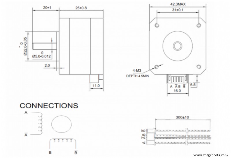
사양 시트가 있는 경우 커넥터의 와이어 순서를 참조해야 합니다. 이 경우 명명법 A A - B B - 가장 일반적입니다.
보드와 모터가 같은 명칭을 사용하는 경우 각 단자를 페어링하는 것처럼 간단하게 연결됩니다. 서로 다른 명명법을 사용하는 경우 다음과 같이 페어링해야 합니다.
사용 가능한 모터 데이터 시트가 없는 경우 각 스풀의 연결 쌍을 결정해야 합니다. 이는 커넥터 핀 쌍의 가능한 모든 조합에서 저항을 측정하여 수행됩니다. 저항이 무한하지 않으면 첫 번째 쌍이 발견된 것입니다. 모터 제조업체에서 사용하는 가장 일반적인 조합은 1-3 4-6 또는 1-4 3-6이므로 먼저 이 두 조합을 테스트해 보세요.
일단 찾으면 각 단계는 각 스풀에 연결됩니다. 두 상이 같은 극성의 코일에 연결되는 것이 중요하므로 역상으로 배치하면 모터에 전류를 보낼 때 움직이지 않고 소음이 발생합니다. 이 경우 코일 중 하나의 극성을 반대로 해야 합니다.
두 상을 분리하는 것이 매우 중요하므로 커넥터의 상태를 자주 확인해야 합니다. 잘못된 접촉이나 상 사이의 브리지로 인해 모터가 작동을 멈춥니다.
스테퍼 모터는 특정 컨트롤러 또는 드라이버를 통해 전원이 공급됩니다. 시장에는 다양한 모델이 있습니다. 품질이 높을수록 일반적으로 더 오래 지속되고 더 조용하게 작동합니다.
사용 가능한 모델에는 모터로 전송되는 전류를 조정하는 두 가지 방법이 있습니다.
max · 8 · Rs
Where Imax is the maximum current at which the motor will be powered (usually at most 90 % of the maximum specified by the manufacturer) and Rs is the detection resistance of the driver.
To adjust it on the driver, simply power up the driver, measure the voltage between the Vref pin (usually the potentiometer itself) and a ground pin (usually the power supply pin) and set the appropriate value using the potentiometer.
When selecting the output current of the drivers, it is not advisable to use the maximum value determined by the manufacturer. In order to prolong the service life of the motors, do not exceed 90 % of the manufacturer's maximum value, the optimum being the minimum current required to generate sufficient torque to withstand the inertias.
Higher current, in addition to higher torque, also means higher heating, higher motor noise and higher wear.
Stepper motors advance by pulses, so the maximum speed of the motor will depend on the maximum signal frequency that the control board is able to send. In addition, it must be taken into account that usually several motors are working simultaneously, so the frequency for each one will decrease.
For example, if the control board works at 100000 Hz and 4 motors (X,Y,Z and extruder) are working simultaneously, each motor will be controlled at 25000 Hz, or 25000 pulses per second. This means that a 1.9 ° motor without microstepping can rotate at a maximum of 125 rps. In a GT2 8-tooth belt drive system (the most common) this translates into a theoretical maximum linear speed of 3600 mm/s.
In the case of microstepping, the maximum speed would be reduced proportionally, so that if 16 microsteps are used, the maximum speed would be 225 mm/s, but if 256 microsteps are used, it would be reduced to only 14 mm/s.
It is very important to know the operating frequency of the control board, as the combination of a low output frequency with a high microstep setting can cause the maximum allowable speed to be lower than the printing speed, resulting in a significant loss of steps.
When the motion signal is transmitted to the motor, it is sent as a rotation, however the movements included in the print files are linear. This is why the printer must be able to translate the angular movement into a linear one.
The movement is generally transmitted by means of toothed pulleys and belts, so that the step/mm conversion depends on the diameter of the pulleys.
To calculate this, the following formula is simply applied:
steps/mm = (360/P) · MS
2 · π · Rpulley
Where P is the motor pitch, MS the configured microsteps (1 in case of not using microstepping) and Rpulley the radius of the pulley used.
In the case of screw-transmitted movements, it is the pitch of the screw that defines the feed rate. For this purpose, the following formula is simply applied:
steps/mm = (360/P) · MS
A
Where P is the motor pitch, MS the configured microsteps (1 in case of not using microstepping) and A the pitch of the screw thread.
There are also many calculators that make it easier to obtain these values, such as the one offered by Prusa Printers.
Once these values have been obtained, and although in theory they are correct, it is advisable to carry out a precise calibration to compensate for possible manufacturing or assembly defects.
For this purpose, a cube of known dimensions (e.g. 50 x 50 x 50 mm) shall be printed out and the actual dimensions measured. Once this is done, the following formula shall be applied:
steps/mm = Dtheorical · Pactual
Dreal
where Dtheorical is the theoretical size that the part should have, Pactual is the current P/mm setting and Dreal is the measurement value obtained from the printed part.
By introducing the new P/mm value, you should obtain parts with appropriate dimensions.
This guide discusses concepts in a general way and does not focus on a particular make or model, although they may be mentioned at some point. There may be important differences in calibration or adjustment procedures between different makes and models, so it is recommended that the manufacturer's manual be consulted before reading this guide.
3D 프린팅
아시다시피 유압 모터는 자동차, 보트 및 기타 대형 물체와 같은 물체를 움직이는 데 사용됩니다. 그들은 가압 유체를 사용하여 회전 운동을 생성함으로써 작동합니다. 이 동작은 어느 방향으로든 사용할 수 있지만 일부 사람들은 유압 모터의 반대 버전을 실행할 수 있다고 생각합니다. 지금까지 아무도 이 이론을 증명할 수 없었지만 이것이 사실로 판명된다면 미래에 이러한 모터를 사용하는 방식에 큰 영향을 미칠 수 있습니다! 아직은 이론일 뿐이니 너무 큰 기대는 하지 마세요. 그러나 이것이 사실로 밝혀지면 이러한 모터에 대한 몇 가지 흥미로운
유압 모터를 구입할 때 고려해야 할 몇 가지 사항이 있습니다. 모터는 애플리케이션에 충분히 강력해야 할 뿐만 아니라 필요한 기능을 갖추고 있는지도 확인해야 합니다. 이 기사에서는 유압 모터를 선택할 때 고려해야 할 몇 가지 핵심 요소에 대해 살펴보겠습니다. 유압 모터란? 유압 모터는 로터에 동력을 공급하기 위해 유압을 사용하는 전기 모터의 일종입니다. 이러한 유형의 모터는 일반적으로 건설, 광업 및 제조와 같은 산업 응용 분야에서 볼 수 있습니다. 유압 모터는 선박 및 잠수함과 같은 해양 응용 분야에도 사용됩니다. 유압 모터는 무