이 프로젝트 정보
나는 날씨를 보는 것을 좋아하고 그것을 포착하고 그래프로 만들고 싶었습니다. 가정 기상 관측소를 통해 "지금"에 대한 세부 정보를 볼 수 있으며 때로는 지난 시간 또는 하루에 대한 집계를 볼 수 있습니다. 더 많은 일을 하고 싶었고 작업에 Arduino를 사용했습니다. 모든 사람은 온도와 습도, 때로는 기압으로 시작하지만 저는 더 많은 것을 원했습니다! 풍속과 강우 측정은 각각 하드웨어 입력을 원했습니다. i2c 사용을 마스터한 후 AS3935 Lightning Detector와 같은 것을 찾았습니다! 그리고 나서 슬픔이 닥쳤습니다... 기본 Arduino로 작업을 수행할 하드웨어 인터럽트가 충분하지 않았습니다. Sparkfun에는 Photon용 기상 센서 보드도 있지만 여전히 제한적입니다. 일부 센서 없이 선택하고 수행해야 합니다. :-(
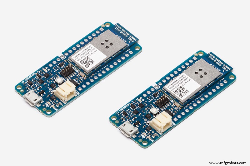
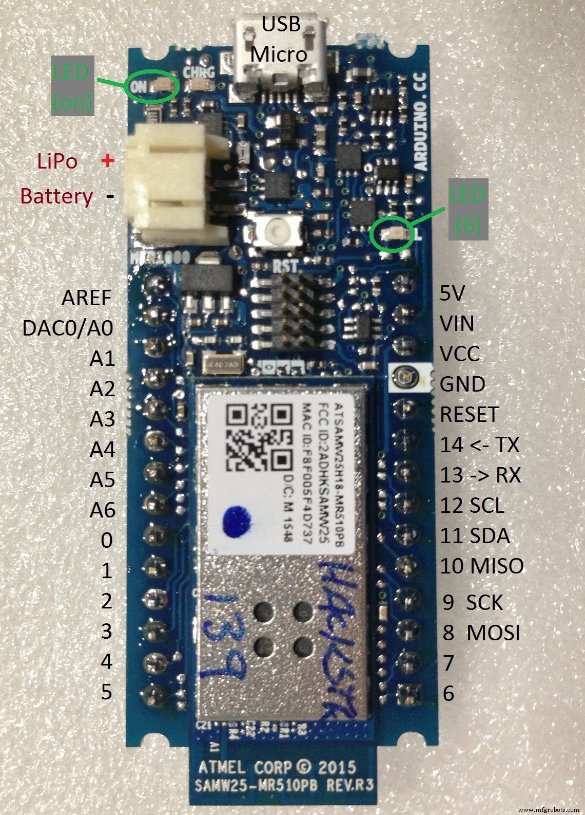
그런 다음 MKR1000 , 그리고 최고의 기능을 발견했습니다. 8개의 하드웨어 인터럽트가 있습니다! 이제 모든 것을 가질 수 있습니다!
센서 선택
센서는 세 가지 기본 유형으로 제공됩니다.
<울> 아날로그 :빛(IR 및 UV 포함), 풍향, 가스, 로드셀...
<울> I2C :온도, 습도, 기압, 가속도계, 자이로...
<울> 인터럽트 :레인 티퍼, 풍속, 번개, 타이머...(직렬, PWM, 시계, 서보와 같은 기능은 타이밍 인터럽트를 사용함)
MKR1000은 이 모든 것을 위한 충분한 I/O를 가지고 있습니다!
I2C 및 인터럽트의 I/O에 필요한 전압을 참고하십시오! 예를 들어, MKR1000, Photon 및 Arduino의 다양한 버전은 5v 대신 3.3v I/O를 사용합니다. CPU와 원하는 센서가 서로 다른 전압을 사용하는 경우 해당 기기 간에 레벨 시프터도 사용해야 합니다.
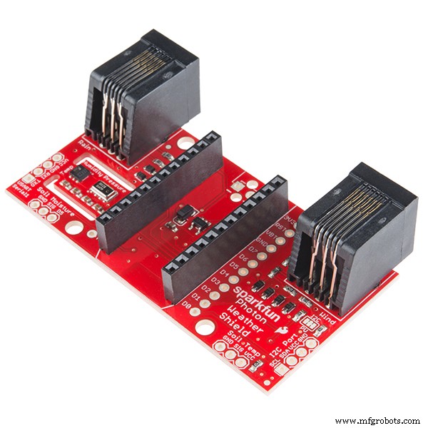
내가 사용하고 있는 모든 센서는 Adafruit, SparkFun, Element-14 등에서 구할 수 있는 충분히 일반적이며 가격은 일반적으로 $5-10(US)입니다. 가스 센서는 일반적으로 $10-$20입니다. 번개 감지기(AS3935 칩)의 경우 보드에 안테나를 설치하는 데 $26(US)인 Embedded Adventures MOD-1016을 선택했습니다. 나는 또한 Photon을 가지고 있기 때문에 Sparkfun Photon Weather Shield를 샀고 아마 그들의 "기상계"(풍속 및 방향 계기)를 살 것입니다. MKR1000을 장착할 위치를 파악하면 토양 수분 센서를 추가할 수 있습니다. 일부 센서는 리드가 긴 것을 좋아하지 않습니다.
핀에 센서 할당
원하는 센서를 알게 되면 어떤 유형의 입력이 필요한지 알게 됩니다. 다음 단계는 어떤 센서가 어떤 핀에 연결될지 결정하는 것입니다. 종이로 시작하지만 미리 알림으로 이 목록을 내 코드의 차단 주석으로 추가할 것입니다.
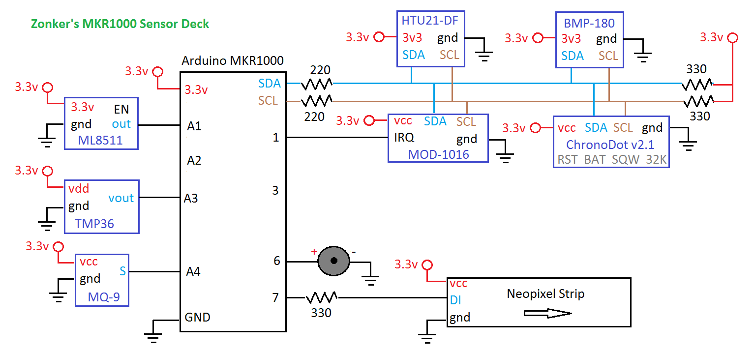
다음은 센서 데크용으로 만든 MKR1000 핀 할당입니다.
<울> A0 (나중에 DAC가 필요할 경우를 대비하여 A0을 아껴두었습니다...)
<울> A1 ML8511 UV 센서
<울> A2 가시광선 센서
<울> A3 TMP36 로컬 온도 센서
<울> A4 MQ-9 가스 센서
<울> A5 수분 센서
<울> A6 풍속 센서?
<울> 0 (HW INT) 푸시버튼
<울> 1 (HW INT) AS 번개 감지기
<울> 2 (HW INT) 풍속 풍속계(회전당 인터럽트)
<울> 3 (HW INT) 레인 티퍼…
<울> 4
<울> 5
<울> 6 (온보드 LED와 공유)
<울> 7 네오픽셀 출력…
시작하기...
초보자 분들은 사용하려는 센서를 하나씩 시작하여 예제 코드를 로드하고 필요한 라이브러리를 설치하는 것으로 시작하는 것이 좋습니다. 센서 핀을 변경하고 선택한 핀 할당과 일치하도록 기억하고 프로젝트 폴더에 데모 코드 사본을 저장하십시오.
테스트 코드를 실행할 수 있고 직렬 모니터에서 결과를 읽을 수 있으면 다른 코드를 추가할 준비가 된 것입니다. 그리고 각 센서의 테스트를 마치면 이제 모두 연결되었으며 더 큰 스케치를 작성할 준비가 되었습니다!
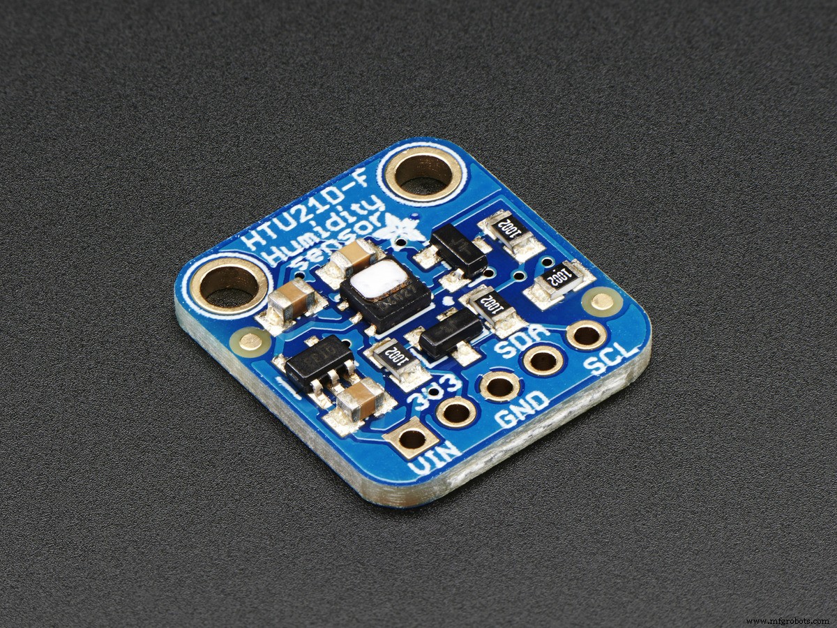
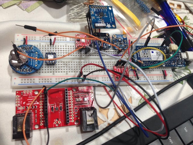
i2c 기반 RTC(Reat-Time Clock)를 사용하여 포함된 센서를 원래 수정하여 SD 메모리 카드에 기록할 수 있었습니다. MKR1000에는 자체 RTC와 배터리가 있지만 배터리만으로는 시간을 맞추지 못해서 ChronoDot v2.1 i2c RTC도 유지하겠습니다.
아래 제 이미지의 브레드보드를 보면 다양한 점퍼가 사용되는 것을 볼 수 있습니다. 주황색은 각 센서에 대한 3.3v 전원용이므로 작업할 준비가 되었을 때만 연결할 수 있습니다. (주황색 점퍼를 뽑으면 센서를 쉽게 비활성화할 수 있습니다.)
라이브러리에 대한 참고 사항
설치할 수 있는 라이브러리 중 일부는 MKR1000 및/또는 Arduino.cc IDE 버전 1.6.7에서 완벽하게 작동하지 않으며 센서의 수명에 따라 약간의 조정이 필요할 수 있습니다. 이다. 이에 대한 한 가지 예는 이전 AVR libc의 이전 ATOMIC_* 매크로입니다. 라이브러리(Arduino IDE 1.6.5에서 삭제됨) 및 Arduino.cc의 포럼 스레드에 문제 및 제안된 솔루션에 대한 훌륭한 스레드가 있습니다. 제안된 변경 사항 중 일부를 만드는 것은 중급 Arduino 해커에게 해당되지만 새로운 해커에게는 겁이 날 것입니다. 그리고 약간 오래된 라이브러리의 경우 원본 작성자가 라이브러리를 업데이트하고 종속성을 제거하지 않을 수 있습니다.
불행히도 일반적으로 센서를 구입하고 테스트하기 전에 어떤 라이브러리를 조정해야 하는지 알 수 없습니다. 이 시점에서 코드 변경을 시작하기 전에 스케치를 주의 깊게 업로드하려고 할 때 주황색으로 표시되는 오류 메시지를 보고 문제가 코드에 있는지 라이브러리에 있는지 확인하는 것이 좋습니다. 라이브러리에 있는 경우 "arduino" 및 오류 메시지에 대한 웹 검색을 수행합니다. 해결 방법을 찾을 수 없는 경우 작성자에게 이메일을 보내 오류에 대해 알려주십시오. 그러면 라이브러리를 업데이트할 수도 있습니다.
나는 돈을 절약하려고 개별 칩을 샀다. 저는 준비가 되어 직접 회로 기판을 만들 수 있을 때까지(아마도 EagleCAD 및 OSHPark를 사용하여) Adafruit 및 SparkFun에서 센서 모듈을 구입하는 것이 더 쉽다고 결정했습니다. Adafruit 및 SparkFun은 라이브러리를 패치한 상태로 유지하는 데 탁월하기 때문입니다.
WiFi 및 암호화에 대한 간략한 설명
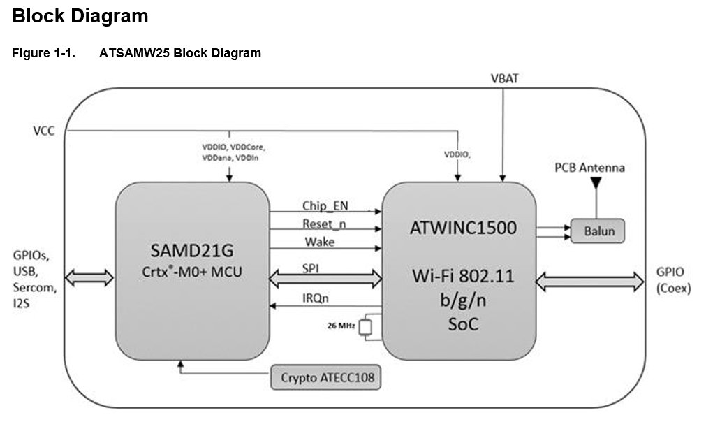
나는 또한 내 날씨 센서가 웹사이트에 보고하도록 하기 위해 Wi-Fi에 대해 생각했습니다. MKR1000에는 암호화 엔진이 있어 인터넷을 통해 전송되는 데이터를 안전하게 보호할 수 있습니다! 그러나 그것은 내가 이 첫 번째 프로젝트에서 할 수 있는 것 이상입니다. 데이터 보안을 설계의 일부로 만드는 것은 사물 인터넷에 중요하기 때문에 해야 할 일이지만 MKR1000 대회에 출품할 시간이 없습니다. 이 프로젝트의 "버전 2"를 살펴보십시오. 다음은 보드의 핵심인 SAMD 모듈의 블록 다이어그램입니다.
온보드 WiFi를 시작하기 위한 한 가지 팁을 드릴 수 있습니다. WiFi101 라이브러리의 최신 버전을 사용하고 있는지 확인하세요! 그렇지 않으면 스케치가 Wi-Fi 모듈을 인식하지 못하며 Wi-Fi 스케치는 Wi-Fi 모듈에 대한 호출을 확인하는 데 오류가 있는 경우에만 보고합니다.) Charif Mahmoudi<에게 감사해야 합니다. /엠> Hackster의 "MKR1000 시작하기" 튜토리얼에서 이를 지적해 주셔서 감사합니다! 제 해킹 당시에는 여기에서 WiFi101 Githuib을 찾을 수 있었습니다.
아날로그 센서를 위한 팁
대부분의 "아날로그 출력" 센서 모듈은 간단한 아날로그 전압 출력을 생성하며 이는 analogRead 를 사용하여 쉽게 읽을 수 있습니다. 센서 핀의 그러나 그 다음이 의미하는 바를 알아야 합니다. 일반적으로 지도 명령을 사용하거나 약간의 수학을 수행해야 할 수도 있습니다. 저항 요소에는 일반적으로 추가 회로가 필요합니다. 전압을 "미세 조정"하기 위해 전위차계를 추가할 수 있습니다.
다른 경우에는 출력 전압을 인간이 이해할 수 있는 것으로 바꾸려면 방정식이 필요합니다. TMP36 온도 센서는 이에 대한 잘 문서화된 한 예입니다. 이 부분은 섭씨로 읽도록 설계되었으므로 전압을 측정하고 C를 얻기 위해 약간의 수학을 해야 합니다. 화씨를 원하면 C를 F로 변환해야 합니다. 구성 요소의 데이터 시트를 읽으면 부품이 어떻게 작동하는지 설명하지만 경험을 쌓다 보면 다른 사람의 발자취를 따라가기가 더 쉬울 것입니다.
그러나 다른 센서에는 ADC가 높은 범위에서 낮은 범위까지 좋은 범위를 얻을 수 있을 만큼 작은 전압 스윙을 크게 만들기 위해 증폭기가 필요합니다. 이러한 유형의 센서(로드 셀, 수분, 가속도계)는 돈을 쓰고 이미 앰프가 있는 모듈과 출력 범위를 이해하는 데 도움이 되는 라이브러리를 구입하는 것이 가장 좋습니다.
I2C 장치 사용을 위한 팁
I2C는 데이터 신호뿐만 아니라 클럭 신호도 필요하기 때문에 "2선 인터페이스"라고도 합니다. ("마스터"와 "슬레이브"가 교대로 데이터를 전송하기 때문에 하나의 데이터 와이어만 필요합니다.) 물론 I2C 센서에는 접지와 전원 리드도 필요하며, 접지 리드는 CPU에 다시 연결해야 합니다.
모든 I2C 장치는 버스에 16진수 주소를 갖습니다. 동일한 주소로 여러 장치를 사용하지 않는 것이 가장 좋습니다. (여러 개의 회로를 갖고 싶다면 통신을 위해 다른 회로를 활성화하기 전에 통신하려는 회로를 "활성화"하고 완료되면 비활성화하기 위해 추가 회로로 관리해야 합니다.) 문서 장치가 될 수 있는 주소를 알려야 합니다. (참고 :주소가 같은 I2C 버스에 두 개의 장치가 있고 둘 다 "활성화" 또는 "종료" 핀이 있는 경우 다른 장치가 깨어 있는 동안 하나를 비활성화할 수 있습니다. 그러나 센서가 SDA 및 SCL 핀에서 일부 전력을 공급받을 수 있고 해당 주소에 대해 잘못된 판독값을 초래할 수 있기 때문에 vdd 핀의 전원을 끌 수는 없습니다. I2C에 대한 오류 검사는 이 경우를 감지/수정하기에 충분하지 않습니다. )
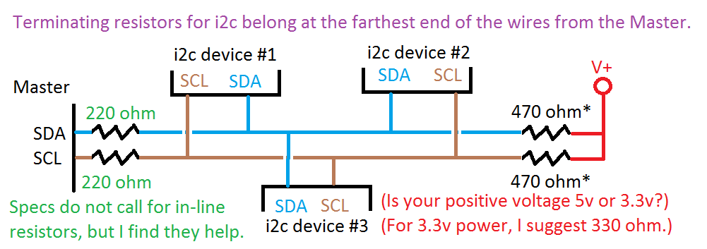
I2C 사양에 따르면 와이어에서 가장 먼 센서의 클록과 데이터 리드 모두에 "강력한" 풀업 저항이 있어야 합니다. 이 때문에 일부 센서 모듈에는 이미 저항이 내장되어 있으며 몇 개의 점퍼만 추가하면 되므로 모듈 설명서를 반드시 읽어보세요.
"버스 종단 저항기" 외에도 데이터(SDA)와 클록(SCL) 리드 모두에 저항을 인라인으로 추가하라는 한 해커의 힌트를 오래전에 찾았습니다. 이것은 몇 개의 센서에서 데이터 판독의 신뢰성을 크게 향상시켰습니다. 3.3v 신호를 사용하는 MKR1000에서는 220옴 저항을 사용하고 있습니다. 5v CPU에서는 330옴을 시도해볼 수 있습니다. 게재위치의 차이를 보려면 아래 도식을 참조하십시오.
데이터로 무엇을 하시겠습니까?
지금은 그냥 시리얼 모니터로 보내는 중입니다. LCD를 추가할 수 있습니다. SD 카드를 추가하려고 했지만 이제 Wi-Fi가 내장되어 데이터를 클라우드에 업로드하고 싶습니다. 이러한 센서 데크가 주변에 몇 개 있고 위도와 경도를 알고 있고 주어진 낙뢰에 대한 각 스테이션의 전력 판독값을 비교하여 낙뢰를 삼각 측량합니다!
옆으로 :2017-11-29; MKR1000에서 작동하는 하드웨어 인터럽트를 얻을 수 없었습니다. 저는 9학년(13-14세) 수업을 위해 메모와 센서 실험을 하고 있으며 스케치가 흥미로울 것입니다. 이 클래스는 Adalogger M0 보드를 중심으로 구축되었으며 데이터를 SD 카드에 저장하며 WiFi 모듈용 핀이 여전히 많이 있습니다. http://arduinoclass.pbworks.com
센서 작업을 하는 동안 IKEA에서 SODERSVIK 램프 고정 장치도 발견했습니다(아래 이미지 참조). 이 램프 내부의 흰색 LED를 20개의 네오픽셀로 교체하고 IR 원격 수신기를 추가한다고 상상해 보십시오. 부는 바람은 구름이 굴러가는 것처럼 보일 수 있으며 색상은 온도를 나타낼 수 있습니다. 리모컨은 지난 12시간 동안의 온도 변화와 같은 다른 정보를 일시적으로 표시하도록 선택할 수도 있습니다.

무엇을 모니터링하고 표시하시겠습니까?
<섹션 클래스="섹션 컨테이너 섹션 축소 가능" id="코드"> 코드
<울> 전체 모니터링 스케치
평균 아날로그 읽기
I2C 버스 스캐너
ML8511 데모 코드
전체 모니터링 스케치Arduino
이 스케치에는 많은 센서 보고가 있으며 라이브러리는 함께 잘 작동합니다. 그러나 AVR-libc의 고전적인 인터럽트 잠금 방법은 NeoPixel 및 Lightning 센서용 라이브러리를 비활성화한 Arduino IDE의 최신 버전에서 제거되었습니다. 올해 안에 이 문제가 해결될 것으로 예상하지만 최종 스케치에서 제외했다는 의미입니다./* RTC-Weather-Sensors_v6_MKR1000 by Zonker Harris Spring 2016 * 만세! 2개 이상의 하드웨어 인터럽트가 있는 작은 보드! * 플러스 WiFi, *및* 암호화(IoT 애플리케이션에 매우 필요합니다!) * * 새로운 해커에 대한 참고 사항:보시다시피 제 코드에 많은 주석을 넣었습니다. * 업로드를 클릭하면 *댓글은 무시*되며 메모리를 먹지 않습니다! * 변경 및 추가할 때 주석을 많이 추가하여 몇 달 전에 한 일을 기억하는 데 도움이 되도록 권장합니다. * 그들은 또한 당신을 뒤따르는 사람들이 한두 가지를 배우도록 도울 것입니다. * * 이제 라이브러리가 *DO* 프로그램 메모리에 포함됩니다... */#include #include #include #include // 네오픽셀 포함 자리 표시자로 사용되지만 라이브러리 인터럽트 벡터를 업데이트해야 합니다.// Adafruit_NeoPixel 라이브러리 포함 https://github.com/adafruit/Adafruit_NeoPixel//#include //const int numLeds =1; // 문자열의 네오픽셀은 몇 개입니까? NeoPixel 라이브러리를 설정하는 데 사용됨 // 매개변수 1 =스트립의 픽셀 수 // 매개변수 2 =핀 번호(대부분 유효함) // 매개변수 3 =픽셀 유형 플래그, 필요에 따라 함께 추가:// NEO_RGB 픽셀은 RGB용으로 연결됨 bitstream // NEO_GRB 픽셀은 GRB 비트스트림에 연결됩니다. // NEO_KHZ400 400 KHz 비트스트림(예:FLORA 픽셀) // NEO_KHZ800 800 KHz 비트스트림(예:고밀도 LED 스트립)//Adafruit_NeoPixel 스트립 =Adafruit_NeoPixel(numLeds,H6) /* BMP085_U 드라이버는 센서 데이터 및 일부 도우미 기능에 대한 공통 '유형'을 제공하는 Adafruit 통합 센서 라이브러리(Adafruit_Sensor)를 사용합니다. (BMP180은 이 라이브러리와 호환되며 동일한 출력을 제공하지만 라이브러리는 BMP180을 BMP085로 식별합니다.) 이 드라이버를 사용하려면 Adafruit_Sensor 라이브러리도 다운로드하여 라이브러리 폴더에 포함해야 합니다. 또한 모든 데이터 로그 등에서 이 특정 센서를 식별할 수 있도록 Adafruit Sensor API와 함께 사용할 이 센서에 고유 ID를 할당해야 합니다. 고유 ID를 할당하려면 아래 생성자에 적절한 값을 제공하기만 하면 됩니다(12345는 이 예에서는 기본적으로 사용됨). */Adafruit_BMP085_Unified bmp =Adafruit_BMP085_Unified(10180);/* 이 스케치는 또한 Adafruit의 HTU21D-F 센서와 함께 작동하도록 설계되었습니다. ----> https://www.adafruit.com/products/1899 */Adafruit_HTU21DF htu =Adafruit_HTU ();/* Macetech Chronodot v2.1 배터리 지원 실시간 시계(RTC)... http://docs.macetech.com/doku.php/chronodot(내 MKR1000의 배터리가 온보드 RTC를 활성 상태로 유지) Adafruit 실시간 시계(RTC) 라이브러리 정보 https://learn.adafruit.com/adafruit-data-logger-shield/using-the-real-time-clock Analog Devices TMP36 아날로그 보정된 온도 센서. 이것은 약간의 수학이 필요합니다 https://learn.adafruit.com/tmp36-temperature-sensor http://www.analog.com/media/en/technical-documentation/data-sheets/TMP35_36_37.pdf ML8511 UV 센서... 이 센서는 280-390nm의 빛을 가장 효과적으로 감지합니다. 이것은 UVB(타는 광선) 스펙트럼의 일부와 대부분의 UVA(태닝 광선) 스펙트럼으로 분류됩니다. MOD-1016(AS3935 번개 센서) i2c 주소 0x03 - AS3935 번개 센서 Adafruit에는 DC 전압 출력(0.4-2.0v)을 제공하는 풍속계가 있습니다. https://www.adafruit.com/products/1733 http://www. instructables.com/id/Breezefinder-Citizen-Science-Windpower-Tool/step2/Build-the-housing/ 토양 수분 감지기(YL-69 센서 또는 이와 유사한 것)에는 아날로그 입력이 필요합니다... http://www.instructables.com /id/Arduino-LCD-Soil-Moisture-Sensor/step3/Connect-moisture-sensor/ My MKR1000 연결(모든 센서는 3.3v 신호여야 합니다!) ==========*/int UVOUT =답1; // MV8511 UV sensorint lightOut =A2에서 출력; // TEMT6000 가시광 센서에서 출력 int tmp36out =A3; // TMP36 로컬 온도 센서의 출력int mq9out =A4; // DFrobot MQ-9 CO/가연성 Gs 센서에서 출력/* A5 수분 센서 A6 풍속 센서? 0(HW INT) 푸시버튼 1(HW INT) AS 번개 감지기 2(HW INT) 풍속 풍속계? (회전당 인터럽트) 3 (HW INT) Rain Tipper… 4 5 */int sounderPin =6; // 피에조 사운더 출력(온보드 LED와 공유)// (점퍼를 사용하여 사운더를 비활성화할 수 있지만 온보드 LED가 깜박임) int neopixelPin =7; // 시프트 레지스터 기반 LED를 사용한 시각화용 NeoPixel 출력/*11 i2c SDA 12 i2c SCL */ // Chronodot i2c RTC...int addrRTC =(0x68); // RTC i2c addressint 초; //RTC에서 결합된 BCD (00h)int 초1; //0-9int 초10; //0-5int 분; //RTC(01h)에서 결합된 BCD int minutes1; //0-9int 분10; //0-6int 시간; //RTC에서 결합된 BCD (02h)int hour1; //0-9 int 시간10; //0-2int 일; //1-7 (03h) int 날짜; //01-31 (04h)int 월; //01-12 (05h)int 년; //0-99; (06h)int a1secs; // (07h) 알람 1초를 얻습니다.int a1mins; // (08h) 알람 1분 받기 a1hrs; // (09h) 알람 1시간을 가져옵니다.int a1daydate; // (0Ah) 알람 1일 및 날짜를 가져옵니다. bitsint a2mins; // (0Bh) 알람 2분 받기 a2hrs; // (0Ch) 알람 2시간을 가져옵니다. a2daydate; // (0Dh) 알람 2 날짜 및 날짜를 가져옵니다. bitsint rtcstatus; // (0Eh) RTC 상태 가져오기 bitsintaginginfo; // (0Fh) 에이징 오프셋 정보를 얻습니다. // 10h는 무엇입니까?int temprtc; //RTC에서 결합된 BCD (11h)int tempfrtc; //RTC에서 결합된 BCD(12h)/****************************************** ***********************************/// Arduino 설정 기능(시작 시 자동 호출)/** ************************************************** **********************/void setup(void) { Serial.begin(9600); 지연(1000); Serial.println("i2c Sensor Deck");// 입력 및 출력 핀을 설정하는 것을 잊지 마십시오! 핀모드(UVOUT, 입력); // ML8511 UV 센서 pinMode(lightOut, INPUT); // TEMT6000 가시광선 센서 pinMode(tmp36out, INPUT); // Analog Devices TMP36 온도 센서 pinMode(sounderPin, OUTPUT); // HIGH는 사운더에서 노이즈를 발생시킵니다. pinMode(neopixelPin, OUTPUT); // 스트립에 인라인으로 220옴 저항기를 사용합니다. /* BMP085/BMP180 센서를 초기화합니다. */ if(!bmp.begin()) { /* BMP085/180을 감지하는 데 문제가 있었습니다... 연결 */ Serial.print("죄송합니다. BMP085/180이 감지되지 않았습니다... 배선 또는 I2C ADDR을 확인하십시오!"); 동안(1); } /* 이 센서에 대한 몇 가지 기본 정보를 표시합니다. BMP180은 BMP085로 보고합니다. */ displaySensorDetails();/* HTU21D 센서를 초기화합니다. */ if (!htu.begin()) { Serial.println("HTU21을 찾을 수 없습니다. -DF 센서!"); 동안 (1); }// Chronodot RTC 시계 초기화//(값을 변경하고 주석을 제거한 다음 업로드하여 시간을 설정한 다음 다시 주석 처리) /* 초 =0; 분 =41; 시간 =20; 일 =7; 날짜 =3; 월 =1; 년 =16; initChrono();*/}무효 루프(무효) { beep(50, 2); // 사운더에서 루프 시작을 알립니다. // 네오픽셀을 청록색으로 설정합니다... //int red =0; 정수 녹색 =45; 인트 블루 =30; //strip.setPixelColor(0, (빨강, 초록, 파랑)); //strip.show();/******************************************** *****************************//* Chronot 정보 i2c 주소 0x68 - DS1307 RTC 끌어오기 *//* 보드 정보:http //docs.macetech.com/doku.php/chronodot *//* DS3231 데이터시트:http://datasheets.maxim-ic.com/en/ds/DS3231.pdf *//********* ************************************************** *************/ int temprtc; /* 새로운 타임스탬프 얻기 */ Wire.beginTransmission(0x68); // 0x68은 DS3231 장치 주소입니다. Wire.write((byte)0); // 레지스터 0에서 시작 Wire.endTransmission(); Wire.requestFrom(0x68, 13); // 19바이트 요청(바이트 수는 DEC 또는 HEX입니까?) // (초, 분, 시, 일, 날짜, 월, 시간, // a1secs, a1mins, a1hrs // a1secs, a1mins, a1hrs // Aging 오프셋, 임시 정수, 임시 분수) while(Wire.available()) { 초 =Wire.read(); // (00h) 초 가져오기 분 =Wire.read(); // (01h) 분 가져오기 시간 =Wire.read(); // (02h) 시간 가져오기 day =Wire.read(); // (03h) 요일 가져오기 date =Wire.read(); // (04h) 월의 날짜 가져오기 =Wire.read(); // (05h) 월, 세기 비트 년 가져오기 =Wire.read(); // (06h) 연도 가져오기 int a1secs =Wire.read(); // (07h) 알람 1초 받기 int a1mins =Wire.read(); // (08h) 알람 1분 가져오기 int a1hrs =Wire.read(); // (09h) 알람 1시간 가져오기 int a1daydate =Wire.read(); // (0Ah) 알람 1일 및 날짜 비트 가져오기 int a2mins =Wire.read(); // (0Bh) 알람 2분 가져오기 int a2hrs =Wire.read(); // (0Ch) 알람 2시간 가져오기 int a2daydate =Wire.read(); // (0Dh) 알람 2 날짜 및 날짜 비트 가져오기 int rtcstatus =Wire.read(); // (0Eh) RTC 상태 비트 가져오기 intaginginfo =Wire.read(); // (0Fh) 에이징 오프셋 정보 얻기 temprtc =Wire.read(); // (11h) temp의 정수 부분을 가져오고 서명 tempfrtc =Wire.read(); // (12h) temp의 분수 부분을 얻습니다. // 비트를 읽고 선행 0 패딩으로 데이터를 정규화합니다. // 참고:Chronodot은 일광 절약 시간에 대해 알지 못하므로 코드를 작성해야 합니까? 초10 =((초 &0b11110000)>>4); 초1 =((초 &0b00001111)); // BCD를 십진수로 변환 minutes10 =((분 &0b11110000)>>4); 분1 =(분 &0b00001111); // BCD를 십진수로 변환 hour10 =(((hours &0b00100000)>>5)*2 + ((hours &0b00010000)>>4)*1); 시간1 =(시간 &0b00001111); // BCD를 10진수로 변환(24시간 모드로 가정) years =(years + 2000); temprtc =((temprtc &0b01111111) + (((tempfrtc &0b11000000)>>6)*0.25)); } get_date(); // 이것은 일광 절약 시간제 결정을 추가하여 시간을 변경할 수 있는 한 곳입니다... Serial.print("ChronoDot - "); Serial.print(시간10); Serial.print(시간1); Serial.print(":"); Serial.print(분10); Serial.print(분1); Serial.print(":"); Serial.print(초10); Serial.print(초1); Serial.print(" 20"); Serial.print(년); Serial.print(" "); Serial.print(월); Serial.print(" "); Serial.print(날짜); Serial.print(" \t"); Serial.print(temprtc); Serial.println("C"); 지연(100); // 다음 센서가 멈춘 경우를 대비하여 인쇄를 완료합니다. /********************************** ************************************//* Get BMP180 data i2c address 0x77 - BMP180 Baro Pres and Temp *//* data:http://www.adafruit.com/datasheets/BST-BMP180-DS000-09.pdf *//******************* ************************************************** */ sensors_event_t event; bmp.getEvent(&event); /* First we get the current temperature from the BMP085/BMP180 */ float BMPtemperature; bmp.getTemperature(&BMPtemperature); float BMPtempF =(BMPtemperature * 1.8 + 32); Serial.print("Temp:"); Serial.print(BMPtemperature); Serial.print(" C ("); Serial.print(BMPtempF); Serial.print(" F) \t"); /* Display the results (barometric pressure is measure in hPa) */ if (event.pressure) { /* Display atmospheric pressue in hPa */ Serial.print("BMP180 - Pres:"); Serial.print(event.pressure); Serial.print(" hPa\t"); /* Calculating altitude with reasonable accuracy requires pressure * * sea level pressure for your position at the moment the data is * * converted, as well as the ambient temperature in degress * * celcius. If you don't have these values, a 'generic' value of * * 1013.25 hPa can be used (defined as SENSORS_PRESSURE_SEALEVELHPA * * in sensors.h), but this isn't ideal and will give variable * * results from one day to the next. * * * * You can usually find the current SLP value by looking at weather * * websites or from environmental information centers near any major * * airport. * * * * convert inches-mercury http://www.csgnetwork.com/pressinmbcvt.html * * * For example, for Paris, France you can check the current mean * * pressure and sea level at:http://bit.ly/16Au8ol */ /* Then convert the atmospheric pressure, and SLP to altitude */ /* Update this next line with the current SLP for better results */ float seaLevelPressure =SENSORS_PRESSURE_SEALEVELHPA; Serial.print("Alt:"); Serial.print(bmp.pressureToAltitude(seaLevelPressure, event.pressure)); Serial.println(" m"); 지연(100); // so this will finish printing, in case the next sensor is stalled } else { Serial.println("Sensor error"); } /**********************************************************************/* Get HTU21-DF data i2c address 0x40 - Humidity and Temp Sensor */* Then convert the atmospheric pressure, and SLP to altitude */* Update this next line with the current SLP for better results */* https://learn.adafruit.com/adafruit-htu21d-f-temperature-humidity-sensor/overview/**********************************************************************/ float HTUtemperature =htu.readTemperature(); float HTUtempF =(HTUtemperature * 1.8 + 32); Serial.print("HTU21-DF - Temp:"); Serial.print(HTUtemperature); Serial.print(" C ("); Serial.print(HTUtempF); Serial.print(" F)\tHum:"); Serial.print(htu.readHumidity()); Serial.println("%"); 지연(100); // so this will finish printing, in case the next sensor is stalled/**********************************************************************/* Analog Devices venerable TMP36 precision temperature sensor/* this requires a bit of math after reading the output.../* https://learn.adafruit.com/tmp36-temperature-sensor/using-a-temp-sensor/**********************************************************************/ //getting the voltage reading from the temperature sensor int reading =averageAnalogRead(tmp36out); // 0.0032258064516129 are the DAC unit for 3.3v float tmp36voltage =0.0032258064516129 * reading; // print out the voltage Serial.print("TMP36 - temp:"); float tmp36temperatureC =(tmp36voltage - 0.5) * 100; //converting from 10 mv per degree with 500 mV offset to degrees ((voltage - 500mV) times 100) Serial.print(tmp36temperatureC); Serial.print(" C \t"); // now convert to Fahrenheit float tmp36temperatureF =(tmp36temperatureC * 9.0 / 5.0) + 32.0; Serial.print(tmp36temperatureF); Serial.print(" F, out:"); Serial.print(tmp36voltage); Serial.println("v"); 지연(100); // so this will finish printing, in case the next sensor is stalled/********************************************************************** * Vishay TEMT6000 Visible Light sensor - analog reading * https://www.sparkfun.com/products/8688/**********************************************************************/ int vLevel =averageAnalogRead(lightOut); // 0.0032258064516129 is (3.3v (the DAC ref voltage) \ 1023 * uvLevel) float newVOutVolts =0.0032258064516129 * vLevel; Serial.print("TEMT6000 out:"); Serial.println(vLevel); 지연(100); // so this will finish printing, in case the next sensor is stalled /********************************************************************** * ML8511 UV Sensor - analog reading * https://learn.sparkfun.com/tutorials/ml8511-uv-sensor-hookup-guide */**********************************************************************/ int uvLevel =averageAnalogRead(UVOUT); // 0.0032258064516129 is (3.3v (the DAC ref voltage) \ 1023 * uvLevel) float newOutVolts =0.0032258064516129 * uvLevel; //Convert the voltage to a UV intensity level float uvIntensity =mapfloat(newOutVolts, 0.99, 2.8, 0.0, 15.0); Serial.print("ML8511 UV out:"); Serial.print(uvLevel); Serial.print(" / UV Intensity (mW/cm^2):"); Serial.println(uvIntensity); 지연(100); // so this will finish printing, in case the next sensor is stalled/********************************************************************** * DFrobot MQ-9 CO/Combustable Gas sensor - analog reading * http://www.dfrobot.com/wiki/index.php/Analog_Gas_Sensor(MQ9)_(SKU:SEN0134) * https://www.pololu.com/category/83/gas-sensors There are many available * But, deciphering what the output levels mean is an exercise for the buyer. :-(/**********************************************************************/ int MQ9volts =analogRead(mq9out); // Read Gas value from the MQ-9 sensor Serial.print("MQ-9 Gas:"); Serial.println(MQ9volts,DEC); delay(100); // so this will finish printing, in case the next sensor is stalled Serial.println(""); delay(3500); // looking to time the loop at about 5 seconds... // End of the main loop...}/**************************************************************************//* The code below are supporting subroutines */**************************************************************************//* Chronodot-related subroutines * * initChrono, set_date, get_date, set_time, get_time, get_temp, * * setHour, SetMinutes, decToBcd, bcdToDec *//**************************************************************************/void initChrono(){ set_time(); set_date();}void set_date(){ Wire.beginTransmission(104); Wire.write(4); Wire.write(decToBcd(day)); Wire.write(decToBcd(date)); Wire.write(decToBcd(mont h)); Wire.write(decToBcd(years)); Wire.endTransmission();}void get_date(){ Wire.beginTransmission(104); Wire.write(3);//set register to 3 (day) Wire.endTransmission(); Wire.requestFrom(104, 4); //get 4 bytes(day,date,month,year); day =bcdToDec(Wire.read()); date =bcdToDec(Wire.read()); 월 =bcdToDec(Wire.read()); years =bcdToDec(Wire.read());}void set_time(){ Wire.beginTransmission(104); Wire.write((byte)0); Wire.write(decToBcd(seconds)); Wire.write(decToBcd(minutes)); Wire.write(decToBcd(hours)); Wire.endTransmission();}void get_time(){ Wire.beginTransmission(104); Wire.write((byte)0);//set register to 0 Wire.endTransmission(); Wire.requestFrom(104, 3);//get 3 bytes (seconds,minutes,hours); seconds =bcdToDec(Wire.read() &0x7f); minutes =bcdToDec(Wire.read()); hours =bcdToDec(Wire.read() &0x3f);}void get_temp(){ Wire.beginTransmission(104); Wire.write((byte)0); //set register to 0 Wire.endTransmission(); Wire.requestFrom(104, 3);//get 3 bytes (seconds,minutes,hours); seconds =bcdToDec(Wire.read() &0x7f); minutes =bcdToDec(Wire.read()); hours =bcdToDec(Wire.read() &0x3f);}void setHour(){ hours++; if (hours> 23) { hours =0; seconds =0; minutes =0; } set_time();}void setMinutes(){ minutes++; if (minutes> 59) { minutes =0; } seconds =0; set_time();}byte decToBcd(byte val){ return ( (val / 10 * 16) + (val % 10) );}byte bcdToDec(byte val){ return ( (val / 16 * 10) + (val % 16) );}/**************************************************************************//* Displays some basic information on this sensor from the unified sensor API sensor_t type (see Adafruit_Sensor for more information) *//**************************************************************************/void displaySensorDetails(void){ sensor_t sensor;// bmp.getSensor(&sensor); Serial.println("------------------------------------"); Serial.print ("Sensor:"); Serial.println(sensor.name); Serial.print ("Driver Ver:"); Serial.println(sensor.version); Serial.print ("Unique ID:"); Serial.println(sensor.sensor_id); Serial.print ("Max Value:"); Serial.print(sensor.max_value); Serial.println(" hPa"); Serial.print ("Min Value:"); Serial.print(sensor.min_value); Serial.println(" hPa"); Serial.print ("Resolution:"); Serial.print(sensor.resolution); Serial.println(" hPa"); Serial.println("------------------------------------"); Serial.println(""); delay(500);}/**************************************************************************//* Takes an average of readings on a given pin, Returns the average */* used for the TMP36 and ML8511 UV Sensor readings./**************************************************************************/int averageAnalogRead(int pinToRead){ byte numberOfReadings =8; unsigned int runningValue =0; for(int x =0; x Taking an Average Analog ReadingArduino
This was a clever hack I found in the SparkFun library for the ML8511 UV Sensor, but I'm calling it out specifically, since you can use it for any analog read! If you ever meet Nathan Seidl, please buy him a beer (it's a Beerware license.)//Takes an average of readings on a given pin//Returns the averageint averageAnalogRead(int pinToRead){ byte numberOfReadings =8; unsigned int runningValue =0; for(int x =0; x I2C bus scannerArduino
If you don't know the base address for your i2c devices, use this to scan the range of valid addresses. It knows about the sensors that I've been working with. You can add sections for your other sensors.// --------------------------------------// i2c_scanner//// Found at http://playground.arduino.cc/Main/I2cScanner?action=sourceblock&num=1// 26 OCT 2015//// Version 1// This program (or code that looks like it)// can be found in many places.// For example on the Arduino.cc forum.// The original author is not know.// Version 2, Juni 2012, Using Arduino 1.0.1// Adapted to be as simple as possible by Arduino.cc user Krodal// Version 3, Feb 26 2013// V3 by louarnold// Version 4, March 3, 2013, Using Arduino 1.0.3// by Arduino.cc user Krodal.// Changes by louarnold removed.// Scanning addresses changed from 0...127 to 1...119,// according to the i2c scanner by Nick Gammon// http://www.gammon.com.au/forum/?id=10896// Version 5, March 28, 2013// As version 4, but address scans now to 127.// A sensor seems to use address 120.//// This sketch tests the standard 7-bit addresses// Devices with higher bit address might not be seen properly.//// Zonk er Harris added device descriptions, comments. OCT 10 2015// #include void setup(){ Wire.begin(); Serial.begin(9600); Serial.println("\nI2C Scanner");}void loop(){ byte error, address; int nDevices; Serial.println("Scanning..."); nDevices =0; for(address =1; address <127; address++ ) { // The i2c_scanner uses the return value of // the Write.endTransmisstion to see if // a device did acknowledge to the address. Wire.beginTransmission(address); error =Wire.endTransmission(); if (error ==0) { Serial.print("I2C device found at address 0x"); if (address<16) Serial.print("0"); Serial.print(address,HEX); // Serial.print(address); If needed, print the address in decimal // // Now, detail sensors that we know about or expect... if (address ==3) { // DEC 3 =0x03 HEX =AS3935 Lightning Sensor Serial.print(" - AS3935 Lightning Sensor"); } if (address ==64) { // DEC 64 =0x40 HEX =HTU21D Humidity and Temp Sensor Serial.print(" - HTU21D Humidity and Temp Sensor"); } if (address ==104) { // DEC 104 =0x68 HEX =DS1307 (Chrono-Dot?) RTC Serial.print(" - DS1307 RTC (Chrono-Dot?)"); } if (address ==119) { // DEC 119 =0x77 HEX =BMP180 Barometric Pressure and Tem Sensor Serial.print(" - BMP180 Barometric Pressure and Tem Sensor"); } Serial.println(" "); nDevices++; } else if (error==4) { Serial.print("Unknow error at address 0x"); if (address<16) Serial.print("0"); Serial.println(address,HEX); if (address ==3) { // DEC 3 =0x03 HEX =AS3935 Lightning Sensor Serial.print(" - AS3935 Lightning Sensor"); } if (address ==64) { // DEC 64 =0x40 HEX =HTU21D Humidity and Temp Sensor Serial.print(" - HTU21D Humidity and Temp Sensor"); } if (address ==104) { // DEC 104 =0x68 HEX =DS1307 (Chrono-Dot?) RTC Serial.print(" - DS1307 RTC (Chrono-Dot?)"); } if (address ==119) { // DEC 119 =0x77 HEX =BMP180 Barometric Pressure and Tem Sensor Serial.print(" - BMP180 Barometric Pressure and Tem Sensor"); } } } if (nDevices ==0) Serial.println("No I2C devices found\n"); else Serial.println("done\n"); 지연(5000); // wait 5 seconds for next scan}/* The output looks like this... * * Scanning... * I2C device found at address 0x03 - AS3935 Lightning Sensor * I2C device found at address 0x40 - HTU21D Humidity and Temp Sensor * I2C device found at address 0x68 - DS1307 RTC (Chrono-Dot?) * I2C device found at address 0x77 - BMP180 Barometric Pressure and Tem Sensor * done * */
ML8511 Demo CodeArduino
Modified for use with a 3.3v-native CPU (for DAC reference units)./* * From https://learn.sparkfun.com/tutorials/ml8511-uv-sensor-hookup-guide 19 MAR 2016 * (Adapted for MKR1000 by Zonker Harris, MAR 2016) ML8511 UV Sensor Read Example By:Nathan Seidle SparkFun Electronics Date:January 15th, 2014 License:This code is public domain but you buy me a beer if you use this and we meet someday (Beerware license). The ML8511 UV Sensor outputs an analog signal in relation to the amount of UV light it detects. Connect the following ML8511 breakout board to Arduino:3.3V =3.3V OUT =A1 GND =GND EN =3.3V * The Sparkfun demo presumes 5v VCC, but the MKR1000 is 3.3v native. * Because of this, the second reference voltage value will always be "1023". * As a result of testing, I cut that part out... -Z- Test your sensor by shining daylight or a UV LED:https://www.sparkfun.com/products/8662 This sensor detects 280-390nm light most effectively. This is categorized as part of the UVB (burning rays) spectrum and most of the UVA (tanning rays) spectrum. There's lots of good UV radiation reading out there:http://www.ccohs.ca/oshanswers/phys_agents/ultravioletradiation.html https://www.iuva.org/uv-faqs *///Hardware pin definitionsint UVOUT =A1; //Output from the sensorvoid setup(){ Serial.begin(9600); pinMode(UVOUT, INPUT); Serial.println("ML8511 example");}void loop(){ int uvLevel =averageAnalogRead(UVOUT); float newOutVolts =0.0032258064516129 * uvLevel; // This is 3.3v \ 1023 * uvLevel float uvIntensity =mapfloat(newOutVolts, 0.99, 2.8, 0.0, 15.0); //Convert the voltage to a UV intensity level Serial.print("ML8511 out:"); Serial.print(uvLevel); Serial.print(" / UV Intensity (mW/cm^2):"); Serial.print(uvIntensity); 직렬.println(); delay(100);}//Takes an average of readings on a given pin//Returns the averageint averageAnalogRead(int pinToRead){ byte numberOfReadings =8; unsigned int runningValue =0; for(int x =0; x 회로도
I'm too new to Fritzing, and couldn't find many parts in the library, so I made this mock-up instead.