

제조공정

산업 제조
 |
| × | 1 | |||

| × | 1 | ||||
| × | 1 | ||||
 |
| × | 1 | |||
 |
| × | 1 | |||
 |
| × | 1 | |||
 |
| × | 1 | |||
| × | 1 | ||||
| × | 1 | ||||
| × | 1 |
 |
|
 |
| |||
 |
| |||
 |
|
알츠하이머 협회 웹사이트(2017년 9월 촬영)에서 직접 인용한 이러한 사실은 자신이나 사랑하는 사람이 알츠하이머병에 걸린 경우 어떤 문제를 겪게 되는지에 대한 아이디어를 제공하기에 충분합니다.
제조사로서 저는 이것에 대해 생각했고 환자와 보호자 모두를 도울 수 있는 시스템인 웨어러블 기기를 제작하기로 결정했습니다.
이 시스템은 최소한 다음 작업을 수행할 수 있어야 합니다.
<울>Infineon의 Sensor Hub Nano를 보았을 때 매우 작은 크기와 BLE 기능으로 인해 이러한 프로젝트에 적합한 후보로 보였습니다. 정확한 압력 감지를 통해 환자가 넘어졌는지 여부를 감지하고 환자가 집에 있는 정확한 위치를 알려주는 데 사용할 수 있습니다.
기본 프로젝트에 다음 부품을 사용할 것입니다. 기능:
<울>
'알츠하이머 보조자 개인화' 섹션을 읽으면 "기본 프로젝트"가 무엇을 의미하는지 알게 될 것입니다.
작동 방식
이 섹션에서는 시계가 어떻게 작동하는지 간략하게 설명하고 작동시키기 위해 거쳐야 하는 단계를 간략하게 설명합니다.
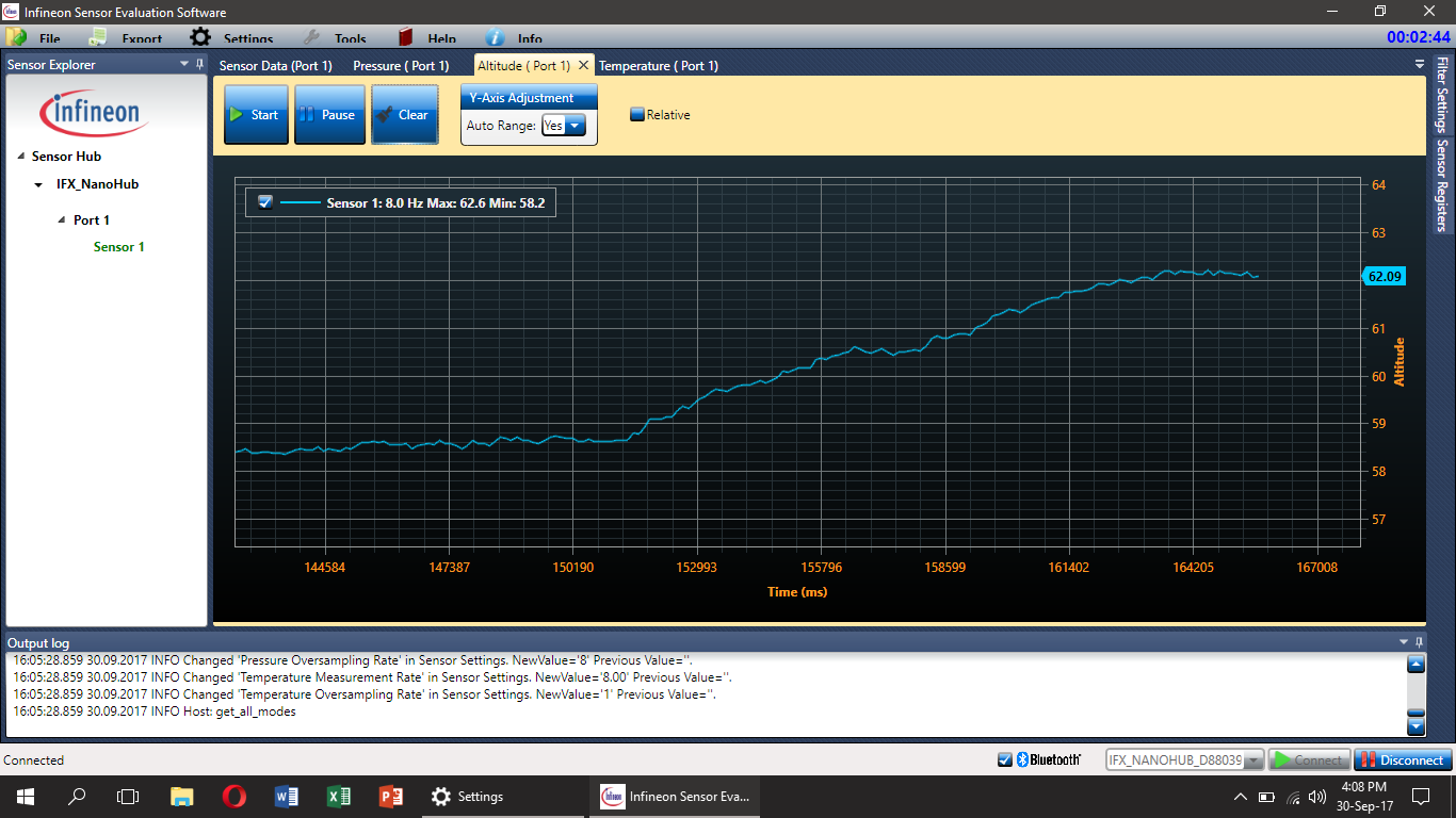
Infineon의 Sensor Hub Nano 평가 기판에는 블루투스를 통해 평가 기판을 통해 데이터를 전송하는 DPS310 기압 센서가 있습니다. 기압, 고도 및 온도 값은 Infineon(여기에서 다운로드)의 Android 앱과 SES2G 평가 소프트웨어에서 볼 수 있습니다. 사용자는 자신의 요구 사항에 따라 Infineon이 제공하는 라이브러리를 사용하여 Android용 애플리케이션을 구축할 수도 있습니다.
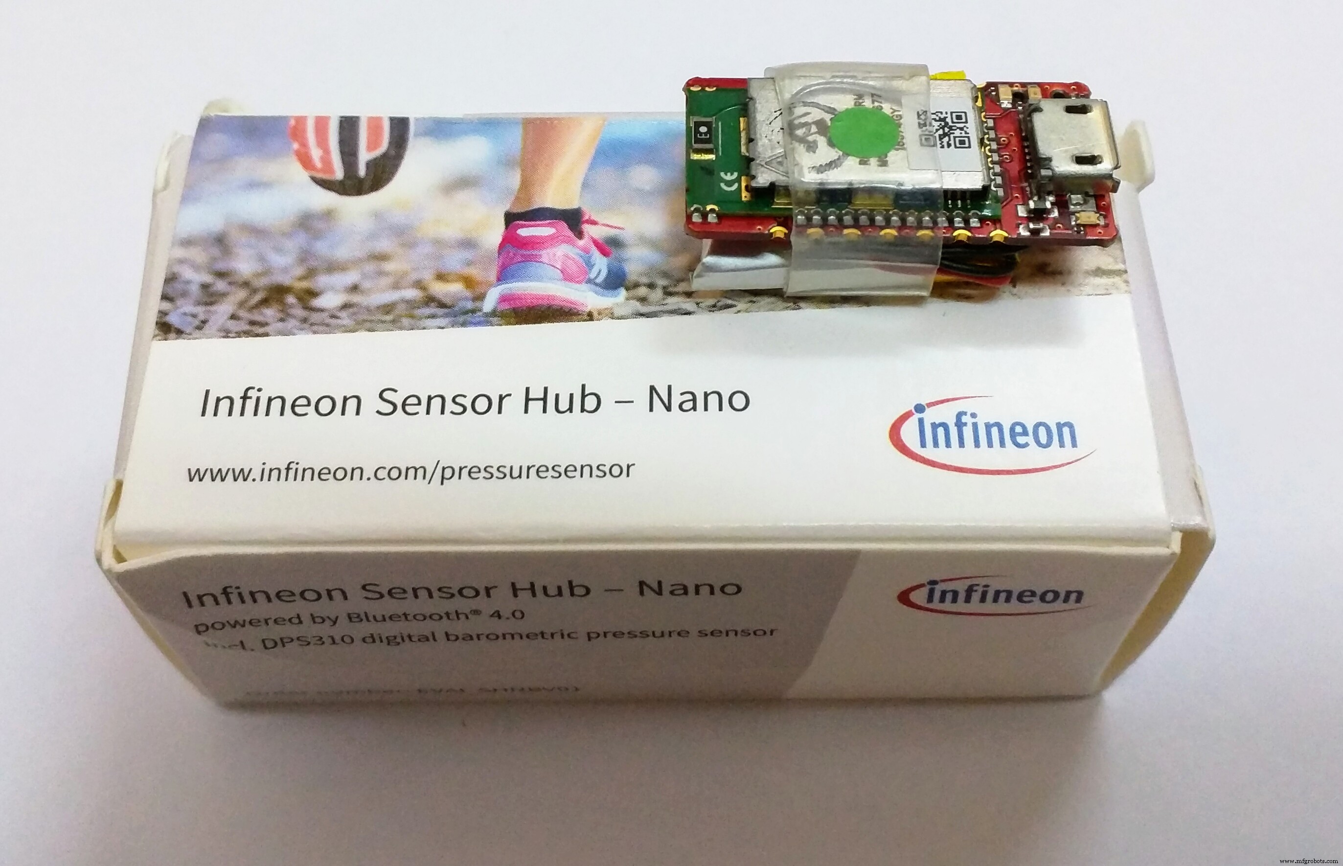
Sensor Hub Nano에 대한 자세한 내용은 여기에서 확인할 수 있습니다.
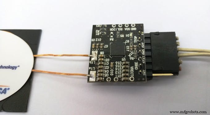
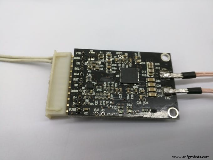
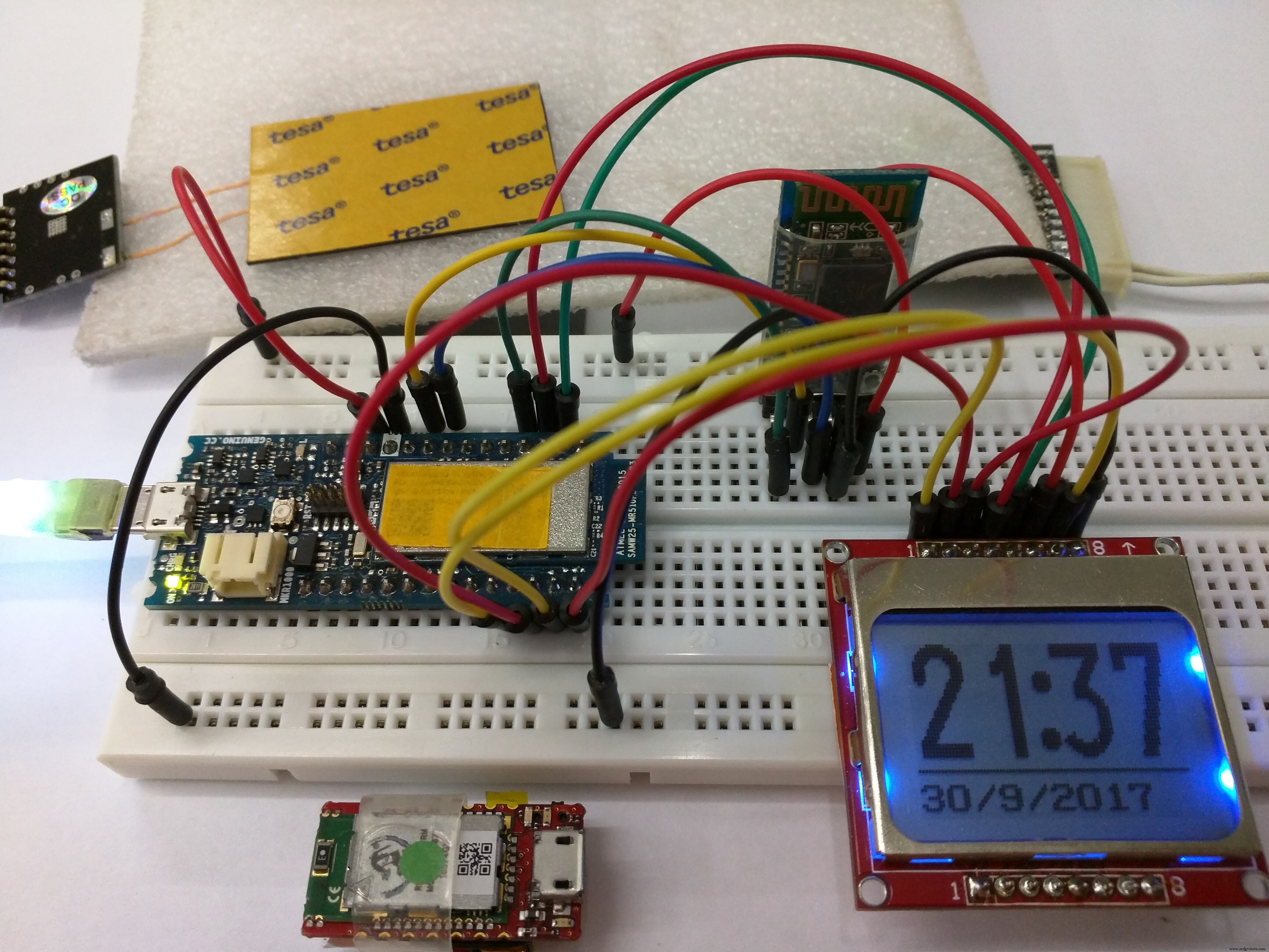
하지만 알츠하이머 어시스턴트가 중간에 안드로이드 폰 없이 작동하기를 바랍니다. 자체적으로 작동할 수 있는 웨어러블이어야 하며, 스마트폰과 연결하여 센서 데이터를 볼 수 있는 기능이 있어야 합니다. 그래서 작은 폼팩터와 WiFi 기능을 갖춘 Arduino MKR1000 보드를 사용하고, 센서 허브 나노에 어떤 방법으로든 연결하기로 결정했습니다.
이것은 당신이 편리하게 찾을 수 있는 Arduino MKR1000의 핀아웃입니다:
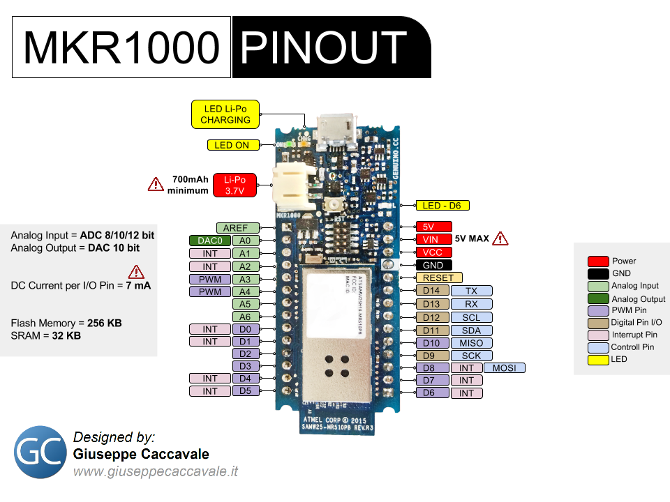
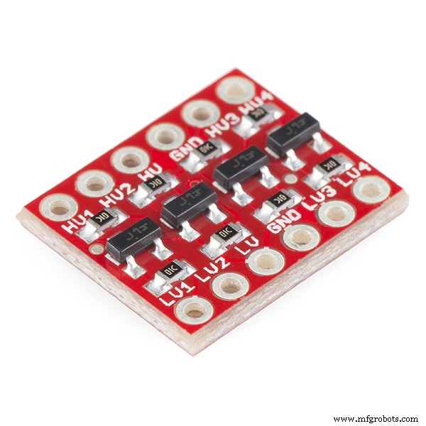
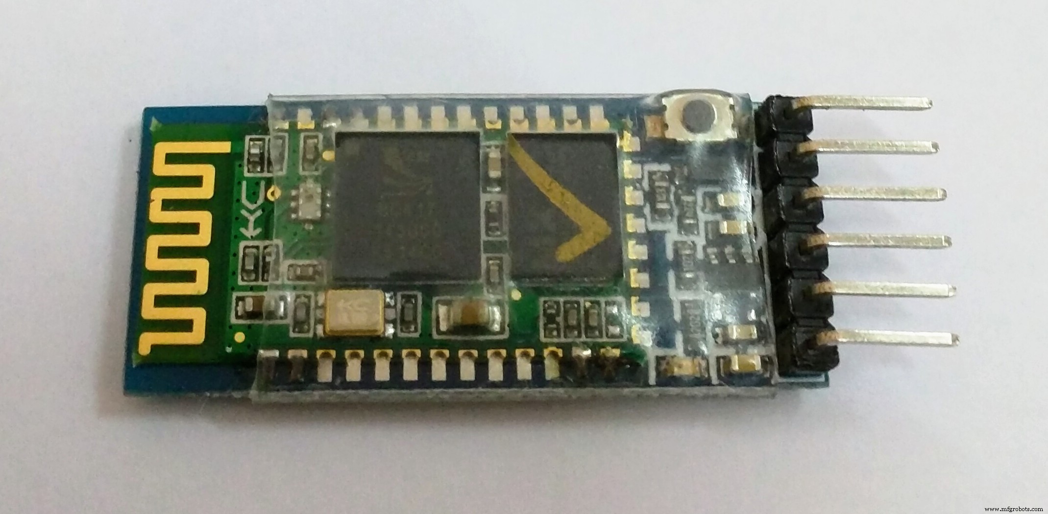
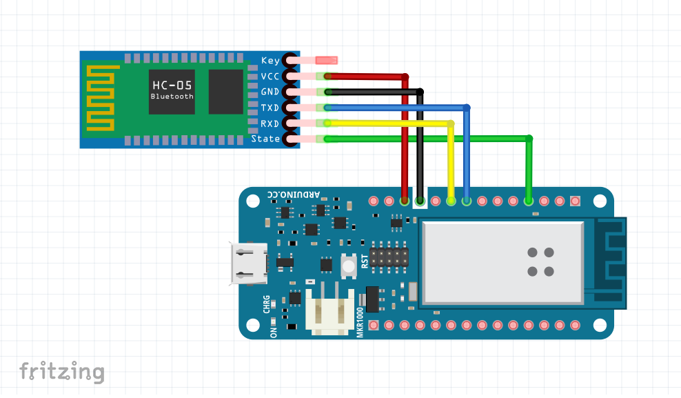
HC-05 블루투스 모듈이 있어서 아두이노 MKR1000과 센서 허브 나노를 연결하기 위해 사용해야 했습니다. 그러나 먼저 로직 레벨을 고려하여 HC-05를 Arduino의 하드웨어 Tx 및 Rx 핀에 올바르게 연결해야 합니다. 내 블루투스 모듈은 MKR1000과 동일한 3.3v에서 작동하므로 전압 레벨 시프터가 필요하지 않았습니다. 그러나 블루투스 모듈이 5v 레벨에서 작동하는 경우 표시된 것과 유사한 레벨 시프터를 사용해야 할 수도 있습니다.
전압 레벨을 일치시킨 후 HC-05를 Sensor Hub Nano와 페어링하여 데이터 통신을 시작하고 Sensor Hub Nano가 HC의 블루투스 범위에 들어갈 때마다 자동으로 페어링하도록 하는 쉬운 방법을 찾아야 합니다. -05.
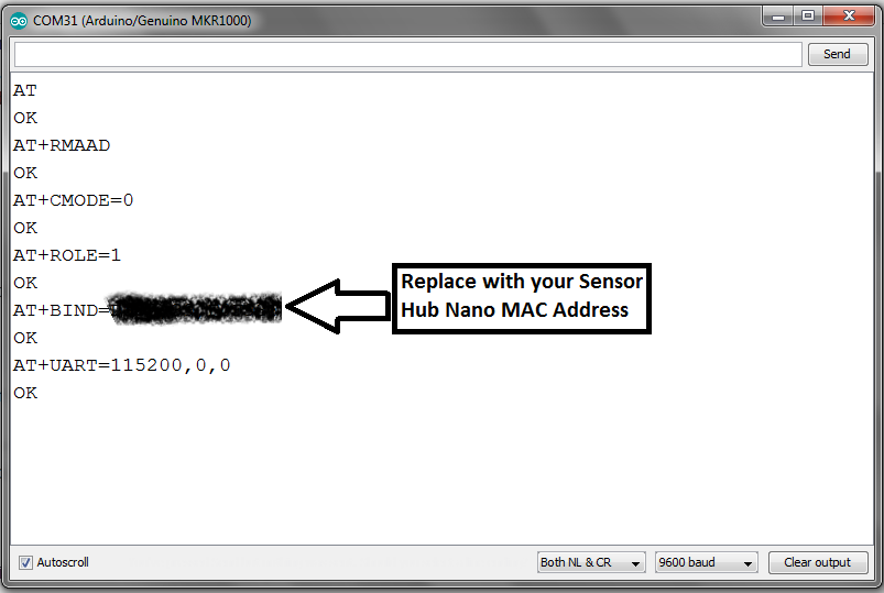
그렇게 하기 위해 HC-05가 블루투스 '마스터' 장치로 작동하도록 구성하고 특정 MAC 주소와만 페어링하는 방법을 생각했습니다. 센서 허브 나노. 이렇게 구성한 후 HC-05를 켜면 특정 MAC 주소(Sensor Hub Nano의 주소)가 있는 장치를 검색하여 자동으로 페어링하여 사용자에게 전송하고 데이터를 수신합니다.
이것은 HC-05에 대한 AT 모드 명령을 사용하여 수행되며 "Bluetooth 모듈 구성" 섹션에서 다룹니다.
참고:HC-05가 지원하는 모든 AT 명령을 나열하는 온라인 문서를 첨부했으므로 필요에 따라 사용하십시오.
페어링되고 제대로 연결되면 Sensor Hub Nano에 명령을 보내는 것은 블루투스 터미널과 같습니다. 위에서 지정한 명령을 HC-05가 연결된 하드웨어 직렬 포트를 통해 단순히 문자열로 인쇄하여 사용할 수 있습니다. 예를 들어, 다음은 센서 데이터 흐름을 시작하기 위해 보낼 명령입니다.
$start_sensor id=1 //센서 데이터의 흐름 시작 내가 알고 있는 명령 목록은 다음과 같습니다.
$hello id=//Hello
$info id=//Info
$sinfo id=1 //센서 정보
$set_mode sid=1;md=mode;val=bg //낮은 에너지
$set_mode sid=1;md=prs_osr;val=16 //표준 모드
$set_mode sid=1;md=prs_mr;val=32 //고정밀도
$start_sensor id=1 //시작
$stop id=//중지
Sensor Hub Nano에서 오는 센서 데이터의 형식은 다음과 같습니다.
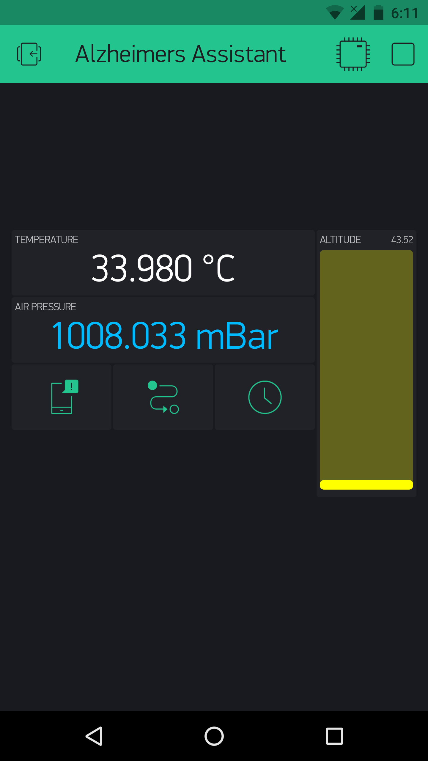
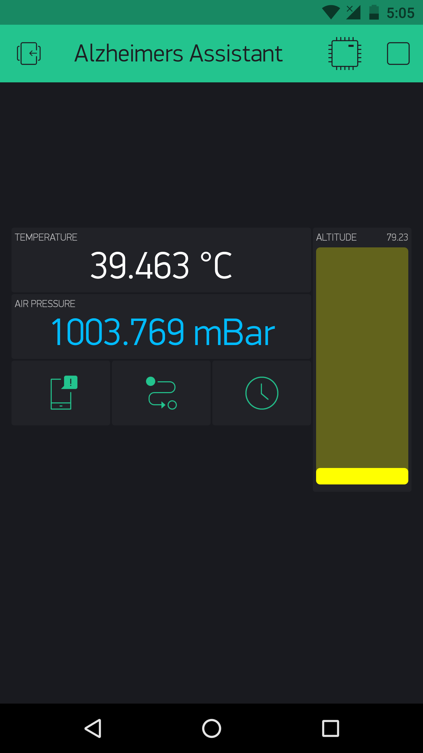
$1,t,36.9299,1154206 //온도
$1,p,997.6813,1154206 //기압
$1,a,130.4305,1154206 //고도
참고:Peter Smith의 블로그 게시물 블루투스를 사용하여 Sensor Hub Nano와 통신을 시작하는 데 도움이 되었습니다.
모듈에서 데이터 흐름을 시작할 수 있게 되면 모듈에서 데이터를 구문 분석할 방법이 필요합니다. 이것은 프로젝트에서 가장 힘든 부분이었습니다. 데이터 흐름을 시작하기 위한 명령을 보내면 Sensor Hub Nano는 데이터 스트림을 보내고 데이터를 수신하는 장치에서 적절한 모든 것을 구문 분석하도록 합니다. 그래서 다양한 복잡성의 많은 방법을 시도한 후(여기에서는 다루지 않겠습니다) Sensor Hub Nano에서 데이터를 구문 분석하기 위해 이것이 제가 생각해낸 가장 간단하고 효율적인 방법이었습니다.
void getSensorValues() {
 //Serial1 포트를 통해 Sensor Hub Nano에서 센서 값을 검색합니다.
 StringjunkVal;
 if (Serial1.available()) {
junkVal =Serial1.readStringUntil('\n');
junkVal =Serial1.readStringUntil('');
 t =Serial1.parseFloat();
junkVal =Serial1.readStringUntil('p');
 p =Serial1.parseFloat();
junkVal =Serial1.readStringUntil('a');
 a =Serial1.parseFloat();
junkVal =Serial1.readStringUntil('\n');
 }
}
디스플레이는 또한 사용자와 상호 작용하고 메시지를 표시하거나 센서의 시간 또는 데이터를 표시하기 위해 Arduino에 연결됩니다. 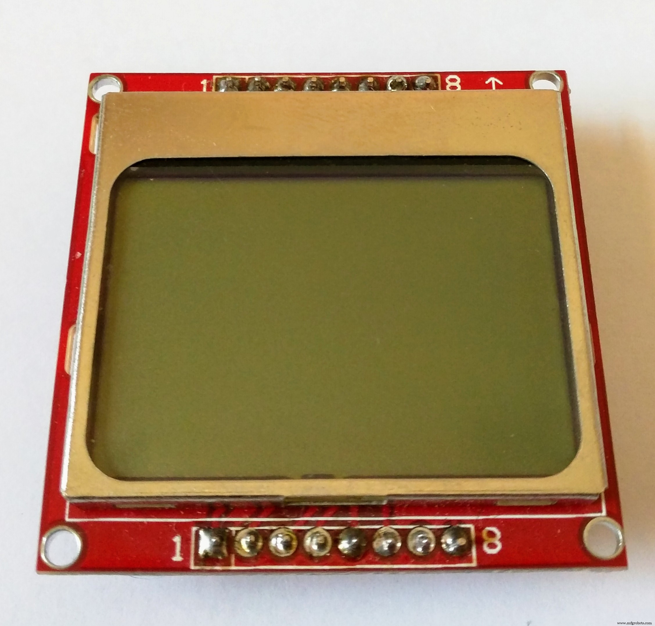
Arduino MKR1000에서 데이터를 받으면 무선 연결로 인해 Cayenne 또는 Blynk와 같은 다양한 IoT 플랫폼으로 데이터를 보낼 수 있습니다.

나는 Cayenne의 아름다운 인터페이스와 쉬운 설정에 깊은 인상을 받았기 때문에 이를 위해 Cayenne을 사용하기로 결정했습니다. 그러나 슬프게도 MKR1000 WiFi 연결에 몇 가지 버그가 있어 핀을 선택할 수 없었습니다. Cayenne에 있는 사람들이 매우 도움이 되었지만 여전히 문제가 해결되지 않았다는 점을 언급해야 합니다. 따라서 결국 Blynk를 사용하기로 결정했지만 사용법이 매우 유사하므로 Arduino 코드 몇 줄만 변경하면 테스트하거나 문제가 발생한 경우 Blynk에서 Cayenne으로 전환할 수 있습니다. 해결. 둘 다 거의 동일한 기능을 가지고 있으므로 자신의 취향일 뿐입니다. 하지만 Cayenne의 유일한 장점은 PC에서도 액세스할 수 있는 반면 Blynk는 스마트폰에서만 작동한다는 것입니다.
이제 Sensor Hub Nano에서 데이터를 받아 Arduino에 가져와 IoT 플랫폼으로 전송했습니다(지금부터 Blynk라고 함). 필요에 따라 다른 섹션에서 다룹니다(낙상 및 위치 감지는 여기에서 논의됨).
참고:나는 각각의 모든 단계를 자세히 문서화하려고 노력했지만, 모르는 것이 있다면(예:Arduino에 코드 업로드) Arduino로 이동하는 것이 더 나을 것입니다. 홈페이지 , 잠시 동안 익숙해졌다가 최소한 기본 사항을 알고 나면 다시 돌아와서 설명합니다.
블루투스 모듈 구성
가장 먼저 해야 할 일은 Sensor Hub Nano 평가 키트의 MAC 주소를 얻는 것입니다. 그렇게 하는 방법은 여러 가지가 있겠지만 제가 한 방법을 말씀드리겠습니다.
Sensor Hub Nano를 스마트폰과 페어링:
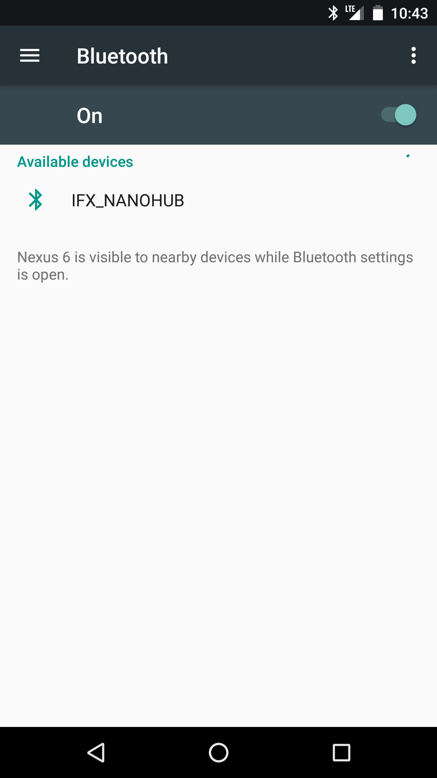

여기에서 Infineon의 Sensor Hub Nano 평가 앱(Android용)을 다운로드하고 Sensor Hub Nano를 켭니다. 앱을 열면 Sensor Hub Nano가 "IFX_NANOHUB"로 표시되고 그 아래에 MAC 주소가 표시됩니다.
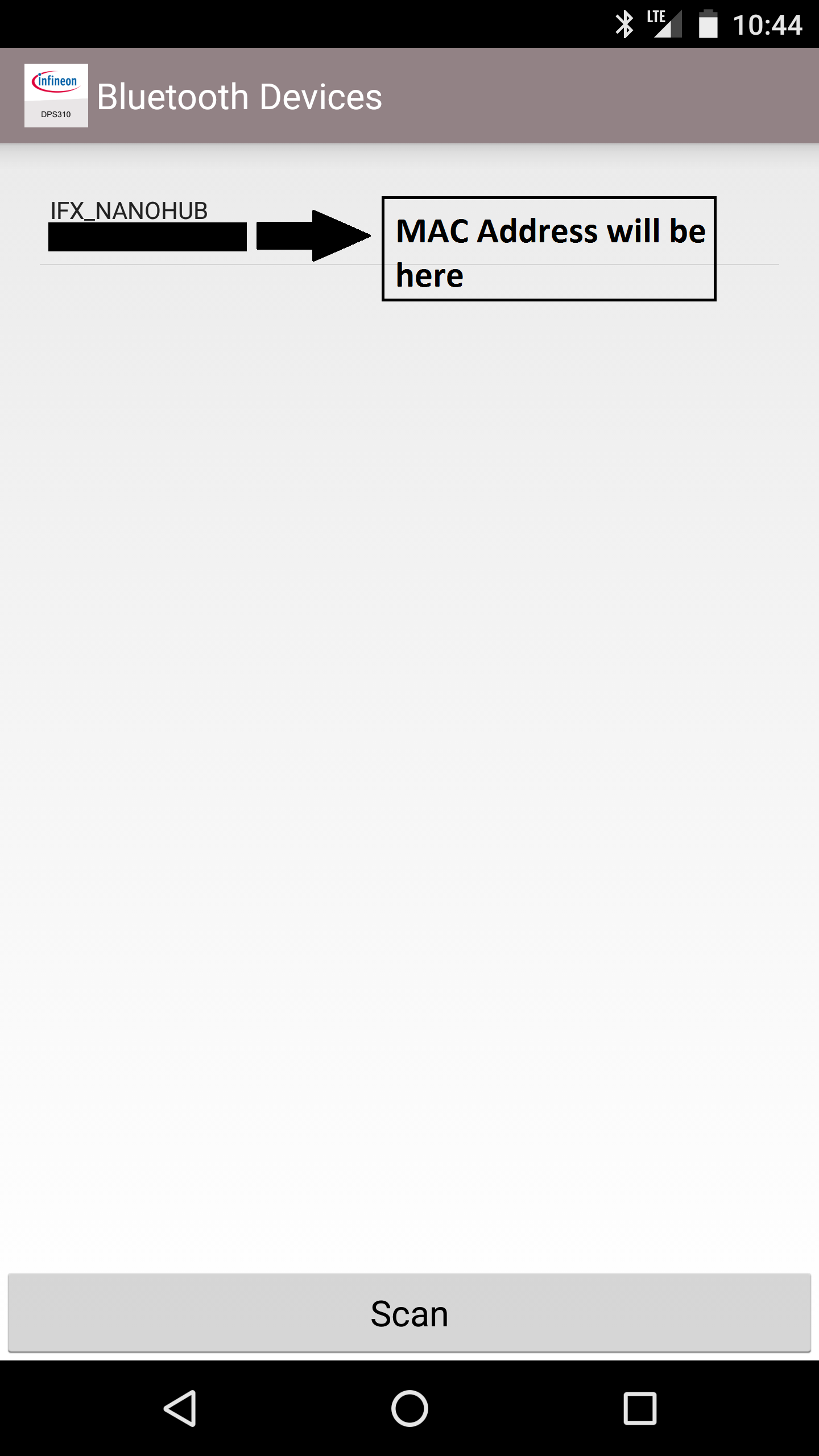
나중에 필요하므로 메모해 두십시오.
참고:지금 사용하지 않는 경우 스마트폰에서 Sensor Hub Nano의 페어링을 해제하는 것이 좋습니다. 휴대전화가 블루투스가 켜져 있고 Sensor Hub Nano가 페어링되어 있는 경우 휴대전화가 자동으로 연결되기 때문입니다. . HC-05를 설정하고 Nano Hub와 페어링하려고 하면 단순히 연결되지 않습니다.
HC-05를 AT 모드로 전환:
AT 모드를 사용하면 HC-05 블루투스 모듈의 설정을 구성할 수 있습니다. 전송 속도를 설정하거나 슬레이브 또는 마스터 장치 등으로 연결할지 여부를 설정합니다. Infineon의 Sensor Hub Nano에서 데이터를 성공적으로 검색할 수 있도록 모듈의 일부 설정을 변경해야 합니다.
먼저 "AT Commands" 스케치를 Arduino MKR1000에 업로드합니다. 이를 통해 Arduino MKR1000을 통해 AT 모드에서 Bluetooth 모듈에 명령을 내릴 수 있습니다.
// Martyn Currey 블로그의 원본 스케치:
// http://www.martyncurrey.com/arduino-with-hc-05-bluetooth-module-at-mode/
//
// Arduino MKR1000과 함께 작동하도록 스케치를 수정했습니다!
//
// 기본 블루투스 스케치
// HC-05 모듈을 연결하고 직렬 모니터를 사용하여 통신
//
// HC-05 기본값 처음 전원을 켤 때 commincation 모드로.
// AT 모드로 설정해야 합니다.
// 공장 초기화 후 통신 모드의 기본 전송 속도는 38400입니다.
char c =' ';
void setup() {
 // 호스트 컴퓨터와 직렬 통신 시작
 Serial.begin(9600);
 Serial.println("HC-05가 있는 아두이노가 준비되었습니다.");
 // 38400을 사용하여 HC-05와 통신 시작
 Serial1.begin(38400);
 Serial.println("시리얼1은 38400에서 시작되었습니다.");
}
void loop() {
 // HC-05에서 계속 읽고 Arduino 직렬 모니터로 전송
 if (Serial1.available())
 {
 c =Serial1.read();
 Serial.write(c);
 }
 // Arduino 직렬 모니터에서 계속 읽고 HC-05로 보냅니다.
 if (Serial.available())
 {
 c =Serial.read( );
 // 명령을 직렬 모니터로 다시 미러링합니다.
 // 명령을 쉽게 따르도록 합니다.
 Serial.write(c);
 Serial1.write(c);
 }
}
그런 다음 그림과 같이 블루투스 모듈만 Arduino MKR1000에 연결합니다.
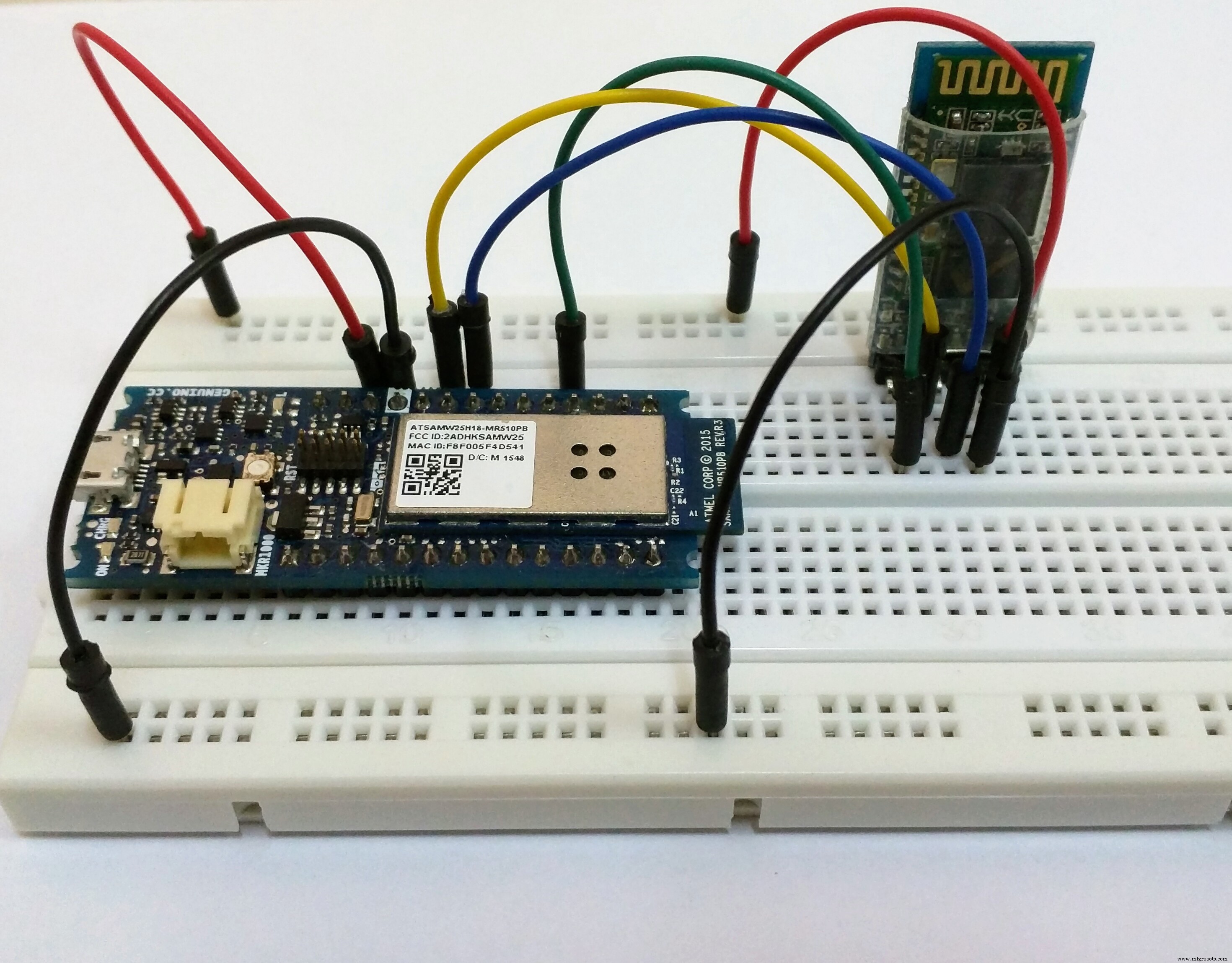
참고:먼저 브레드보드에 모든 것을 배선하고 올바르게 설정했으면 적절한 배선을 진행하는 것이 좋습니다.
Sensor Hub Nano와 HC-05를 켜려고 하면 현재 자동으로 연결되지 않는 것을 볼 수 있습니다. 다음과 같이 표시됩니다.
HC-05 설정을 변경하려면 블루투스 모듈을 AT 모드로 전환해야 합니다. 이 작업을 수행하는 방법은 보유한 브레이크아웃 보드에 따라 다르므로 다르게 수행해야 할 수도 있습니다. 내가 가지고 있는 것과 다른 모듈이 있는 경우 AT 모드에서 HC-05 블루투스 모듈을 얻는 방법에 대한 자세한 정보를 찾을 수 있는 여기 Martyn Currey의 블로그로 이동하십시오. 문제가 있는 경우 Google에 문제나 댓글을 남겨주시면 도와드리겠습니다.
내 블루투스 모듈에는 버튼 스위치가 있으므로 AT 명령 모드로 전환하려면 다음 단계를 수행해야 합니다(AT 명령 코드를 Arduino에 업로드하는 것을 잊지 마십시오).
<울>AT 모드에서 HC-05를 얻는 방법을 보여주는 비디오:
AT 모드에 들어가면 HC-05의 LED 깜박임 패턴에 상당한 차이가 있음을 알 수 있습니다. 통신 모드에서는 LED가 빠르게 깜박이며 AT 모드에서는 2초에 한 번씩 LED가 깜박입니다.
HC-05 모듈 설정:
직렬 모니터를 열고 전송 속도를 9600으로 설정하고 "Both NL &CR"을 선택합니다.
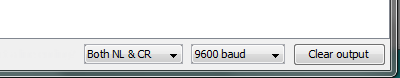
참고:개행 및 캐리지 리턴으로 설정해야 합니다. 그렇지 않으면 AT 명령이 작동하지 않습니다.
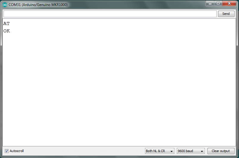
직렬 모니터에 "AT"를 입력하면 "OK"가 표시됩니다. 그렇게 하면 더 진행하여 내가 한 것처럼 명령을 내릴 수 있습니다.
기본적으로 AT 모드에서 다음 설정을 변경해야 합니다.
<울>위의 지시 사항은 다른 블루투스 모듈이 있어도 사용할 수 있도록 명령어와 기능을 참고하여 제공한 것입니다. 하지만 이제 HC-05가 Sensor Hub Nano와 페어링하기 위해 준 명령을 나열하겠습니다.
<울>다음은 참조용으로 내 AT 명령의 로그입니다.
이제 Arduino의 플러그를 뽑아 블루투스 모듈을 꺼야 합니다. 이렇게 하면 통신 모드로 돌아갑니다.
참고:HC-05 설정에 문제가 있는 경우 모듈을 기본 설정으로 재설정하고 AT+ORGL 명령으로 처음부터 시작하는 것이 좋습니다.
연결 테스트:
이제 마지막 단계가 성공했는지 테스트해야 합니다. Sensor Hub Nano를 켜면 됩니다. 파란색 LED가 몇 초에 한 번씩 매우 천천히 깜박입니다. 그런 다음 Arduino를 PC에 연결하고 HC-05와 Sesnor Hub Nano 모두에서 LED 깜박임의 변화를 확인하세요.
지금 깜박임을 보고 이전 깜박임과 비교:
눈에 띄는 차이가 있으며 두 모듈이 모두 연결되어 있음을 알아야 합니다. 이제 프로젝트를 연결하고 테스트하는 다음 부분으로 넘어갈 수 있습니다.
참고:이전에 스마트폰을 Sensor Hub Nano와 페어링한 경우 페어링을 해제해야 할 수 있습니다. 그렇지 않으면 연결 문제가 발생할 수 있습니다. 한 번에 하나의 기기에만 연결할 수 있습니다.
베어본 프로젝트 테스트
LED 점멸 패턴으로 HC-05와 Sensor Hub Nano가 제대로 연결되었음을 확인한 후 스마트폰에서 Blynk 앱 설정을 진행하세요.
Blynk 앱 설정:
여기에서 iOS 또는 Android 장치용 Blynk 앱(아직 다운로드하지 않은 경우)을 다운로드하고 Blynk 앱을 통해 QR 코드를 스캔합니다. 이때 필요한 기본 위젯을 자동으로 복제합니다.

비슷한 화면이 표시됩니다.
지금 여기에서 변경하지 말고 계속 읽으십시오.
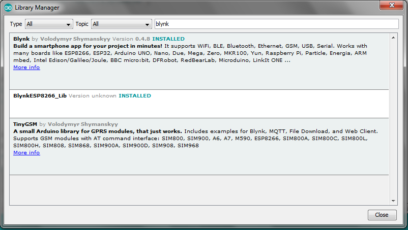
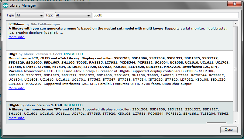
필수 라이브러리 설치:
코드가 오류 없이 컴파일되도록 하려면 Arduino IDE에 대해 두 개의 서로 다른 라이브러리가 설치되어 있어야 합니다. 그들은:
<울>필요한 라이브러리를 설치하는 방법에는 두 가지가 있습니다. 첫 번째는 최신 버전의 Arduino IDE에서 사용할 수 있는 '라이브러리 관리자'를 통한 것이고 두 번째는 수동 설치입니다. 두 가지 방법 모두 여기에 자세히 설명되어 있으므로 자세히 다루지 않을 것이므로 링크를 확인하세요.
코드 업로드 및 테스트:
라이브러리를 설치했으면 첨부된 코드를 다운로드하고 일부를 변경하십시오. Blynk의 인증 코드(Blynk에서 새 프로젝트가 생성될 때 이메일로 전송됨)와 WiFi SSID 및 비밀번호를 추가해야 합니다. 완료되면 코드를 MKR1000에 업로드합니다.
코드를 업로드한 후 회로도에 따라 회로를 배선합니다.

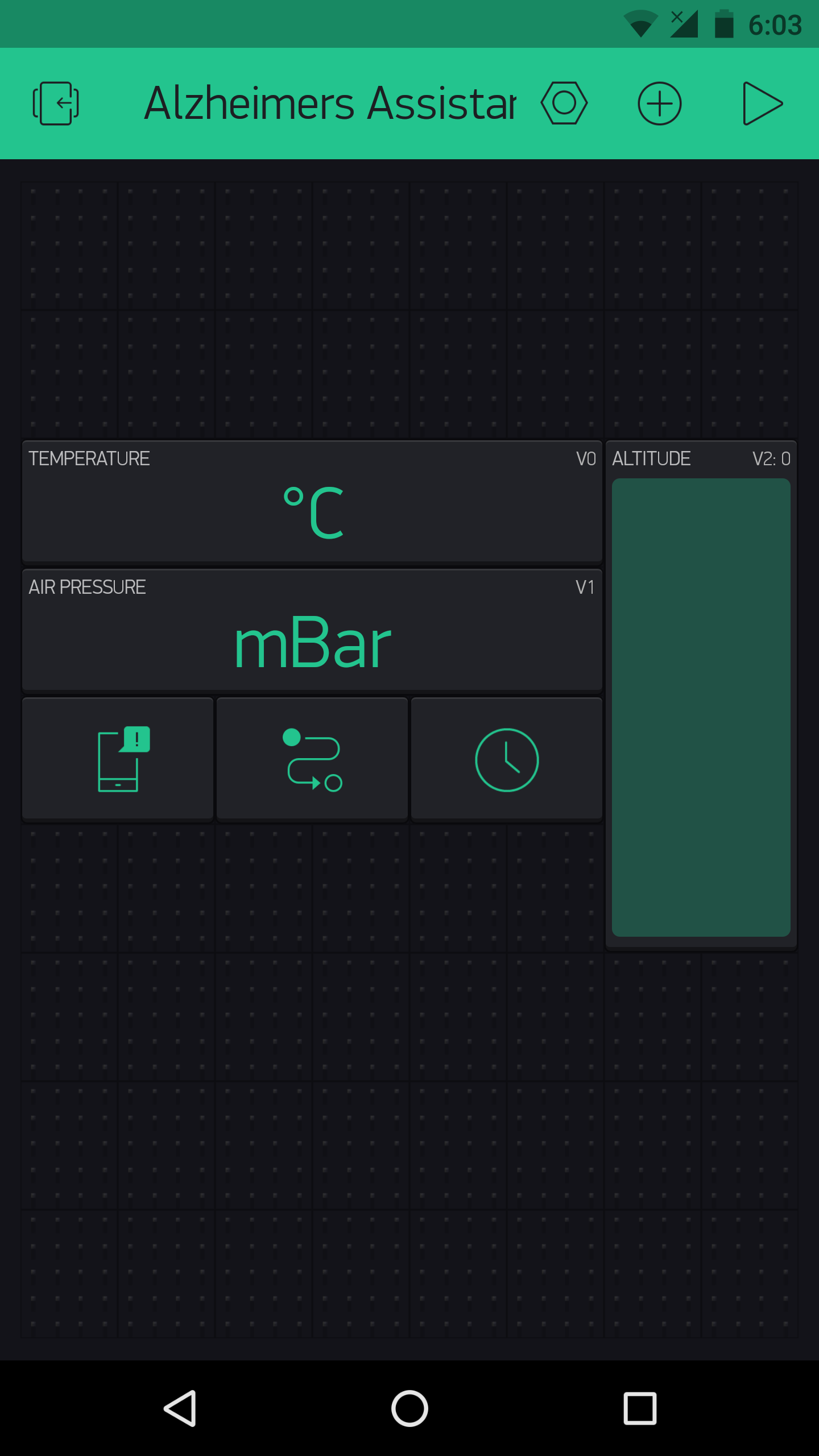
그런 다음 스마트 폰에서 Blynk 앱을 열고 알츠하이머 어시스턴트 프로젝트를 열고 재생 버튼을 누르십시오. MKR1000(HC-05 및 디스플레이가 연결된 상태)을 연결하면 디스플레이에 알츠하이머 어시스턴트 로고가 표시됩니다. 잠시 머물다가 "Sensor Hub Nano를 기다리는 중 메시지를 볼 수 있습니다. ". Sensor Hub Nano의 작은 스위치를 켜서 HC-05 모듈의 블루투스 범위 내에 있는지 확인합니다. "Infineon의 Sensor Hub Nano에 연결됨 "하고 몇 초 후에 스마트폰에 기압 온도와 고도 값이 표시되어야 합니다.
그리고 몇 초 후에 24시간 형식의 시간과 날짜가 표시되며 인터넷과 동기화됩니다.
테스트한 동영상입니다.
그렇다면 축하합니다. 설정의 어려운 부분을 완료했으며 이제 개별 환자의 선호도에 따라 개인화할 수 있습니다.
알츠하이머 어시스턴트 개인화
지금까지 우리가 설정한 것은 깔끔하고 우아한 설정으로 Infineon의 DPS310에서 센서 데이터를 검색하지만, 그로부터 유용한 것을 만들기 위해서는 개별 요구 사항과 기본 설정에 따라 설정을 구성해야 합니다. 따라서 이 섹션에서는 각 사용자의 기호에 따라 알츠하이머 어시스턴트가 작동하도록 코드와 수정하는 방법에 대해 이야기하겠습니다. 각 '기능'에 대한 코드 스니펫을 제공할 것이며 약간의 변경만 가해 기본 코드에 간단히 추가할 수 있습니다.
참고:'기본 프로젝트'에 대해 첨부한 코드를 보면 BlynkTimer에 래핑된 함수를 사용하고 있음을 알 수 있습니다. 지정된 간격으로 작업을 수행할 수 있고 하드웨어가 Blynk에 많은 요청을 보낼 때 발생하는 Blynk 플러드 오류를 방지할 수 있으므로 사용자 정의를 수행하려는 경우 사용하는 것이 좋습니다. 또한 모든 기능이 있지만 기본 코드에 포함되지 않는다는 점에서 코드는 '기본'입니다. 사용자는 요구 사항에 따라 메인 코드를 수정해야 하며, 각 기능이 실행되는 시간 간격을 조정해야 할 수도 있습니다.
DPS310:-
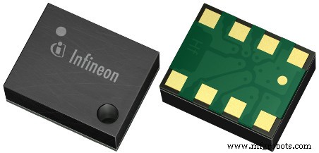
Infineon의 DPS310은 매우 작은 폼 팩터에서 매우 높은 정확도를 제공하는 저렴한 디지털 기압 센서입니다. 그렇기 때문에 이러한 프로젝트에서 사용하기에 적합하며, 값을 사용하여 노인 환자의 낙상을 감지하거나 환자가 정확히 어느 병실에 있는지 감지할 수 있습니다.
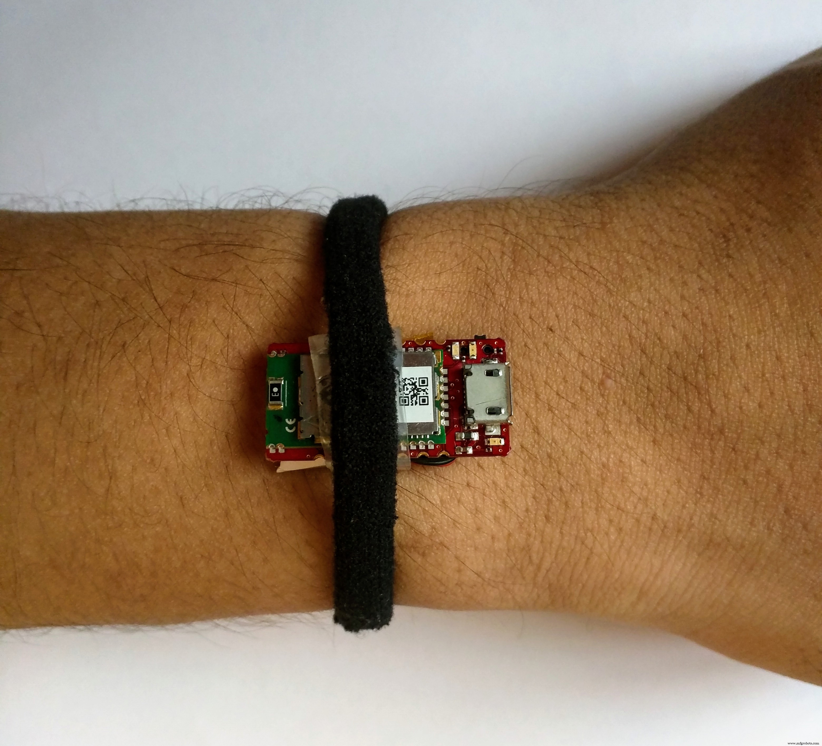
참고:아직 스마트워치 인클로저를 만들지 않았으므로 다음 이미지와 같이 Bluetooth를 통해 Arduino와 연결된 Sensor Hub Nano를 손에 사용하고 있습니다.
낙상 감지: 낙상을 감지하려면 낙상 값(지정된 시간 동안 두 판독값 사이의 기압 차이)을 제공하고 간극을 설정해야 합니다. 예를 들어, 두 개의 연속 값 사이의 고도 변화(1초 동안)가 낙하 값 ± 클리어런스 값 사이인 경우 낙하가 감지됩니다.
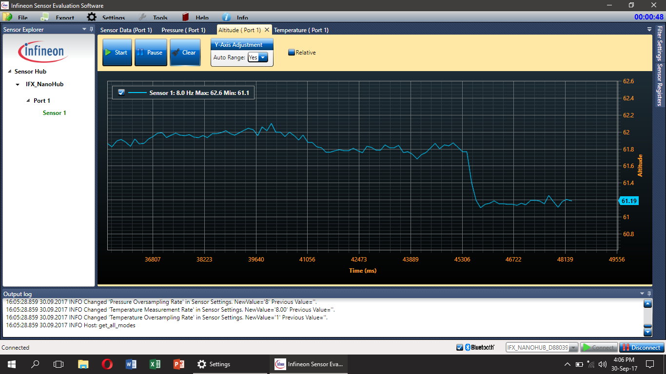
몇 가지 테스트를 수행한 결과 낙하 값은 0.7이어야 하고 클리어런스 값은 ±0.2이어야 하지만 모든 상황에서 작동하지 않을 수 있습니다. 이것은 사람이 넘어지면 여러 가지 방식으로 발생할 수 있다는 간단하고 이해할 수 있는 이유 때문입니다. 따라서 낙상 감지 시스템의 정확도를 높이려면 보조 센서(아마도 가속도계)를 사용해야 하며 향후 작업에 추가될 것입니다. 그러나 낙상을 감지하기 위한 더 정확한 다른 알고리즘이 있을 가능성은 항상 있을 수 있으며 저는 이에 대해 귀를 기울이고 있습니다. 이에 대한 아이디어가 있으면 언제든지 의견을 말하십시오.
추락 감지 시연 동영상:
환자의 위치 감지: 이것은 추락 감지 알고리즘과 유사하게 작동합니다. 예를 들어, 환자가 어느 층에 있는지 알아야 하는 경우 현재 고도 값을 가져와 이전 고도에서 뺄 수 있습니다. 그런 다음 차이를 미리 정의된 값과 비교합니다. 이것은 환자가 몇 층에 있는지를 나타냅니다.
환자가 어느 층에 있는지 결정하기 위해 간단한 if 및 else 논리를 사용하기만 하면 됩니다(고도 값은 기본 코드에 이미 있습니다). Blynk의 LED 위젯을 사용하여 표시할 수 있습니다.
참고:위치 감지를 기본 코드에 포함하지 않았지만 사용자가 필요에 따라 추가할 수 있습니다. Blynk 타이머 기능으로 사용하는 것을 잊지 마십시오.
동일한 기술을 사용하여 사람이 어느 방에 있는지 감지할 수도 있습니다. 이 경우 모션 센서와 같은 보조 센서가 필요합니다. 그렇지 않으면 잘못된 트리거가 많이 발생할 수 있습니다.
온도: DPS310은 또한 예를 들어 화재와 같이 환자에게 발생할 수 있는 사고에 대해 경고하는 데 사용할 수 있는 온도 값을 보여줍니다. 온도가 특정 값으로 올라가면 45℃라고 가정해 봅시다. 간병인에게 경고합니다.
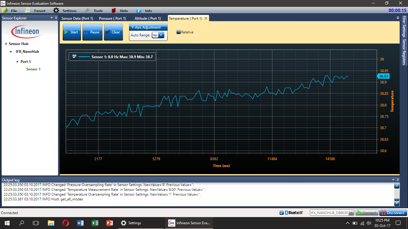
그러나 DPS310 센서는 피부에 직접 부착되지 않기 때문에(적어도 이 사용 사례에서는) 체온이 아니라 Sensor Hub Nano의 온도라고 말하는 것이 더 정확할 것입니다.
이에 대한 코드는 매우 간단하며(메인 루프의 아무 곳에서나 사용) 다음과 같을 수 있습니다.
if (t> maxTemp) {
 //온도가 최대값보다 높으면 원하는 작업 수행
}
else {
 //원하는 작업 수행 온도가 최대값보다 낮은 경우
}
참고:위의 모든 그래프는 Infineon에서 제공하는 SESG2 평가 소프트웨어를 사용하여 생성되었습니다.
부저 및 스위치:-
나는 이것을 전에 언급하지 않았지만 부저와 스위치도 시스템에 있어야하며 그것들도 매우 도움이 될 것입니다. 예를 들어, 부저를 사용하여 약을 복용해야 할 때 환자의 주의를 끌 수 있고 스위치를 안전 장치로 사용할 수 있습니다.
그리고 우리는 Blynk를 사용할 것이기 때문에 버튼 스위치를 눌렀을 때 알림이 관리인의 전화에 나타나거나 SMS를 보내거나 전화를 걸거나(IFTTT를 사용하여 수행할 수 있고 나중에 제공되는 방식으로) 버튼 스위치를 설정할 수 있습니다. ). 다음은 이를 수행하는 코드 스니펫일 수 있습니다.
void emailOnButtonPress()
{
 // *** 경고:15초당 하나의 이메일만 보낼 수 있습니다! ***
 // 버튼을 누르면 이메일을 보내자.
 // Arduino의 디지털 핀 2에 연결됨
 int isButtonPressed =!digitalRead(2); // 버튼이 "Active LOW"이기 때문에 상태를 반전합니다.
 if (isButtonPressed) // 이메일 전송을 트리거하는 조건을 작성할 수 있습니다.
 {
 Serial.println("Button이 눌렸 ."); // 이것은 직렬 모니터에서 볼 수 있습니다.
 Blynk.email("[email protected]", "제목:버튼 로거", "방금 버튼을 눌렀습니다...");
 // 또는 앱에 지정된 이메일을 사용하려는 경우(예:앱 내보내기):
 //Blynk.email("Subject:Button Logger", "방금 버튼을 눌렀습니다. ..");
 }
}
Blynk 샘플 코드에서 가져오고 인터럽트를 사용하여 버튼을 확인합니다. 이것은 환자가 낙상 감지 알고리즘에 의해 감지되지 않은 낙상과 같은 응급 상황에서 간병인에게 경고하는 데 사용할 수 있습니다. 버튼을 누르면 이메일을 보내는 전체 샘플 코드를 여기에서 얻을 수 있습니다.
버저는 신호음을 생성하는 데 사용할 수 있으며(Arduino tone() 명령 사용 - 자세한 정보는 여기에서) 환자에게 약물이나 운동과 같은 작업을 상기시켜줍니다.
디스플레이:-
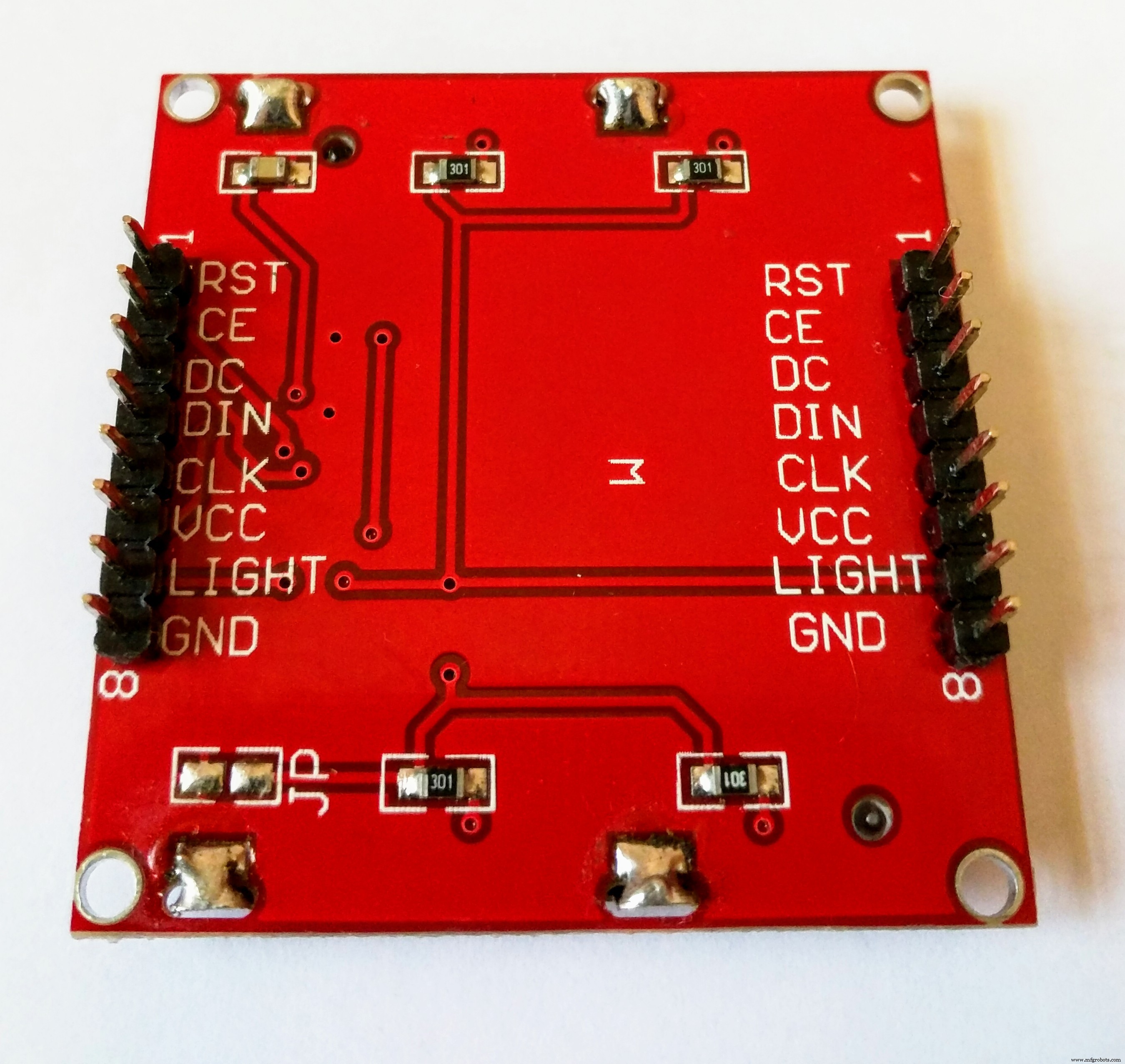
사용자가 실제로 보는 프로젝트의 주요 부분은 디스플레이입니다. Nokia 5110 디스플레이는 일반적으로 사용 가능하고 설정이 쉽고 저렴하지만 특히 이러한 시스템에서 사용할 때 화려하지는 않습니다. OLED displays with a higher resolution will be a very good alternative to it, and you can easily modify the code to work with one because I used the u8g2 library (github here). Choose any of the display models from here, and add it to the start of the sketch (removing the Nokia 5110 line, of course!). You will need to wire it up according to what it is in the code and you’re ready to go. You can also use bitmap images with a higher resolution display. You can also change the font for the text on the display, select fonts from the huge list here and edit the name of the font in the code.
Note:You may have to change the pixel positions for the text in the code if you use a display with a higher resolution.
That was just a brief description of the library used to get the display working. But, now I will tell you how to edit the code to get Alzheimer's Assistant to show the time or the Sensor Hub Nano data (temperature, Altitude and pressure).
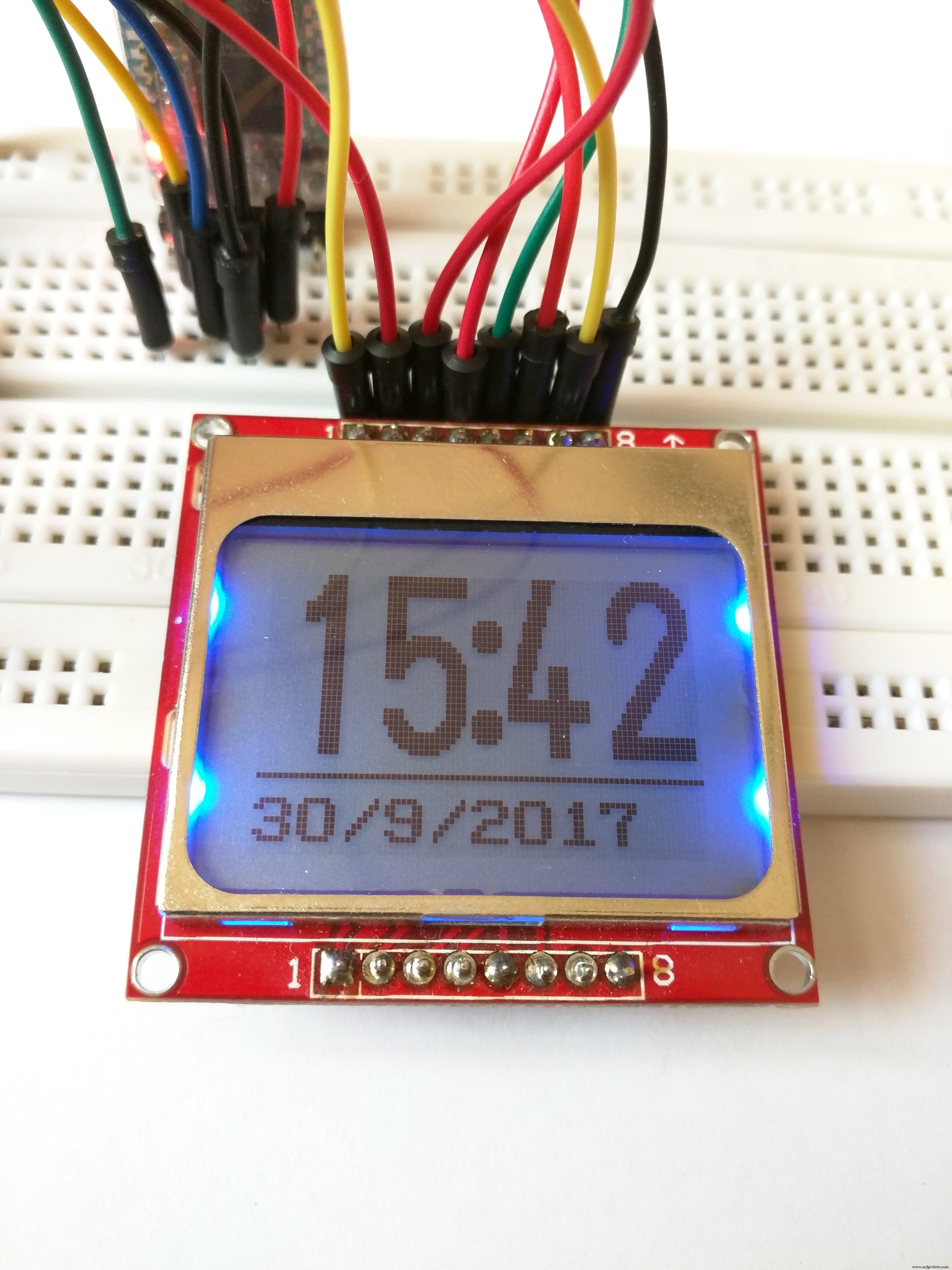
Displaying time: To display the time, you could simply use an RTC (or time keeping module) but as we're connected to the Internet, it would be much more easier to use the Internet to sync the time. And as we're using Blynk that would make it even more simpler. You just need the RTC widget in your project. Now with a few lines of code, you can automatically retrieve the time from the Blynk server (Make sure to set your timezone from the Blynk widget). The main code is set to display the time by default (not the sensor values, discussed next)
Note:The time displayed on the screen could go up or down a minute, as it is synced from the internet, but despite that, I have tested it for a long time and have found it to be very accurate (just a difference of a few seconds).
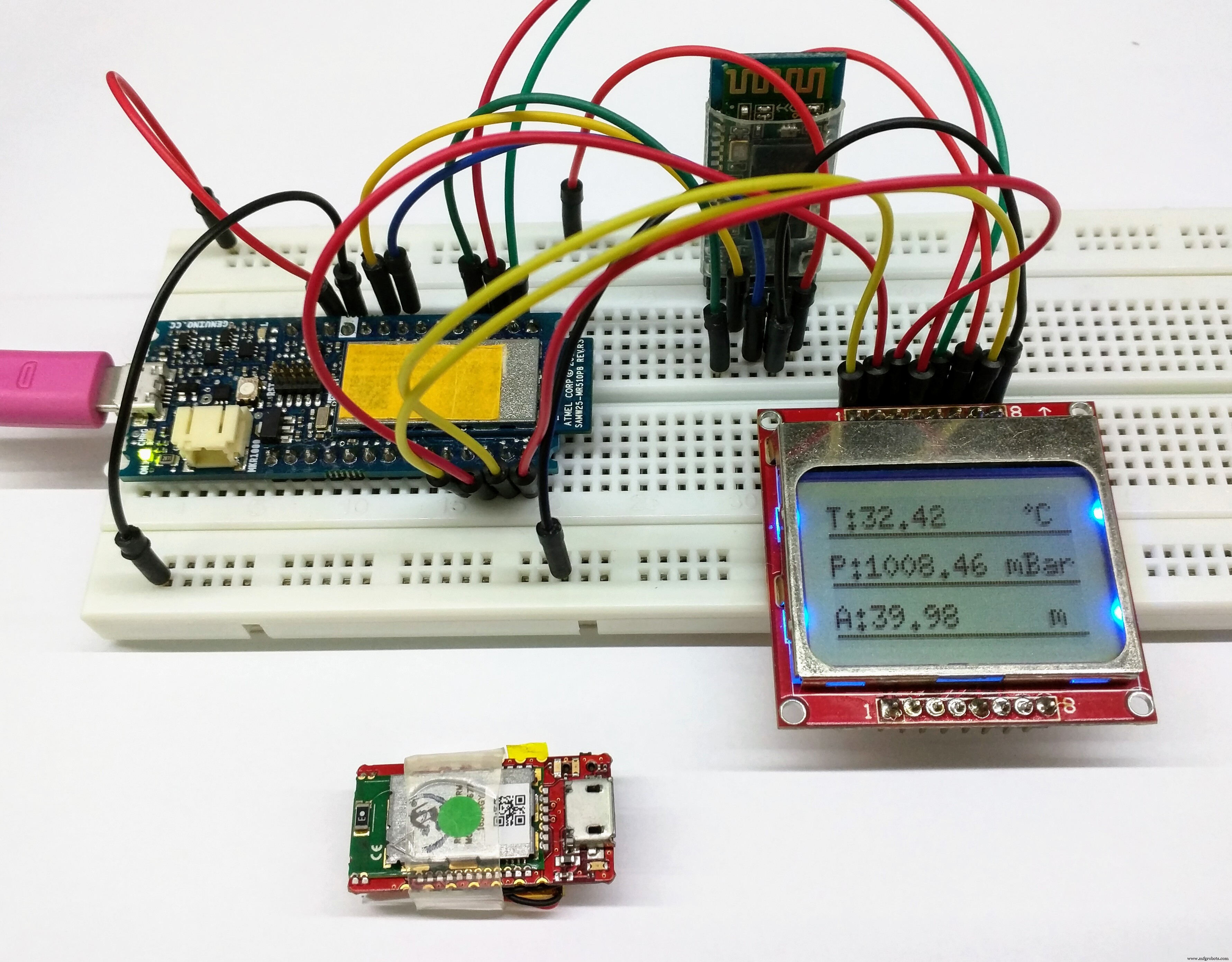
Displaying the Sensor Hub Nano data: We could just as well display data from the Sensor Hub Nano in the display. Not that it would benefit the patient, but its good for debugging purposes, should you need it. That can be done with the following code snippet:
void showSensorValues() {
 //Shows the sensor values on the display
 char bufT[10];
 char bufP[10];
 char bufA[10];
 String(t).toCharArray(bufT, 10);
 String(p).toCharArray(bufP, 10);
 String(a).toCharArray(bufA, 10);
 u8g2.clearBuffer();
 u8g2.setFont(u8g2_font_6x10_tf );
 //Display the temperature
 u8g2.drawStr(0, 10, "T:");
 u8g2.drawStr(12, 10, bufT);
 u8g2.drawStr(73, 10, "C");
 u8g2.drawCircle(70, 4, 1, U8G2_DRAW_ALL);
 u8g2.drawHLine(0, 12, 85);
 //Display the pressure
 u8g2.drawStr(0, 26, "P:");
 u8g2.drawStr(12, 26, bufP);
 u8g2.drawStr(60, 26, "mBar");
 u8g2.drawHLine(0, 28, 85);
 //Display the altitude
 u8g2.drawStr(0, 42, "A:");
 u8g2.drawStr(12, 42, bufA);
 u8g2.drawStr(72, 42, "m");
 u8g2.drawHLine(0, 44, 85);
 //Send the values to the display
 u8g2.sendBuffer();
}
Don't forget to run this command to get the sensor data below:
getSensorValues(); But that's not all for the display. As I said in the start, Alzheimer's Assistant should be able to remind the patient of the tasks which need to be done daily, such as when to take medications or to remind the patient to exercise.
Using Eventor widget to remind:-
For that, we will be using the Eventor widget (check here for details) in Blynk.
Add the Eventor widget into your project (It's already there if you scanned the QR code above), and just follow the screenshots to see how to set it up:
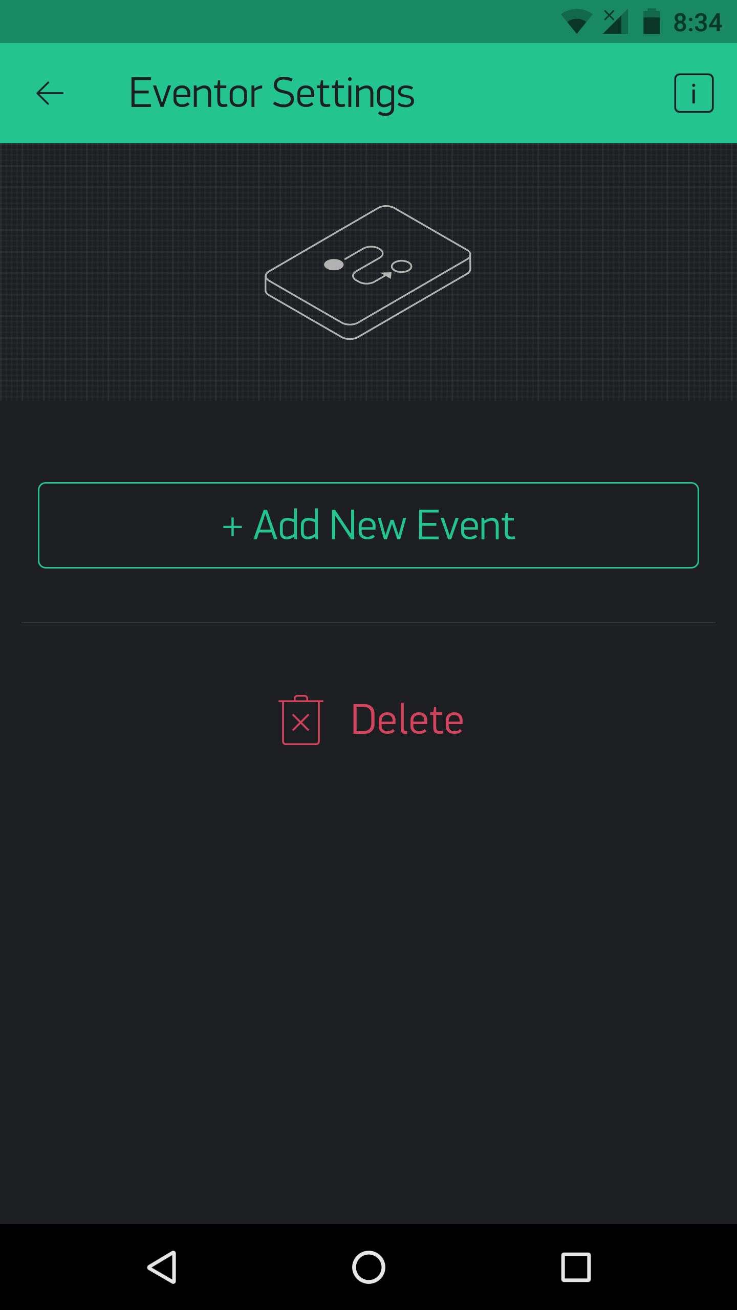
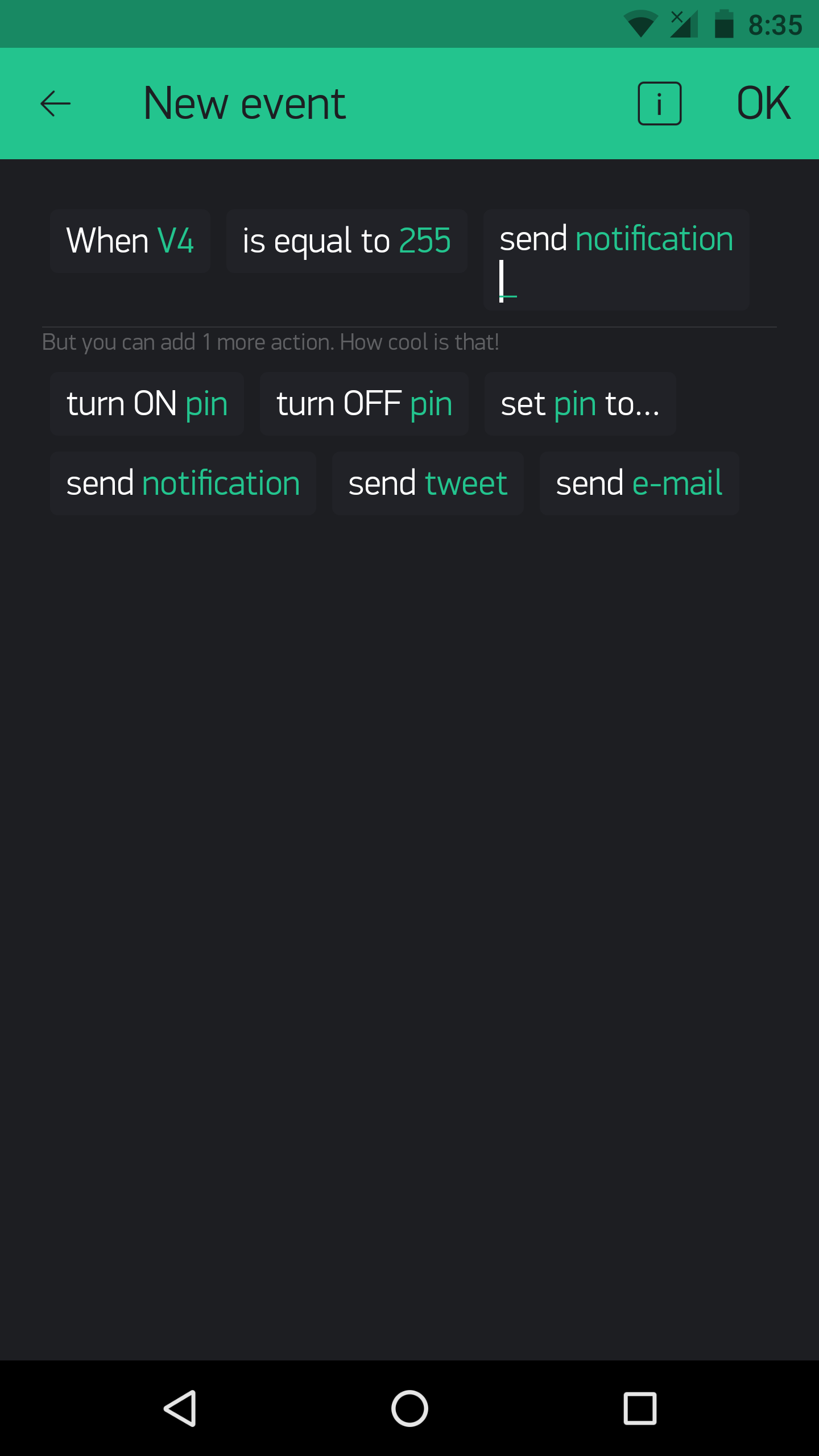
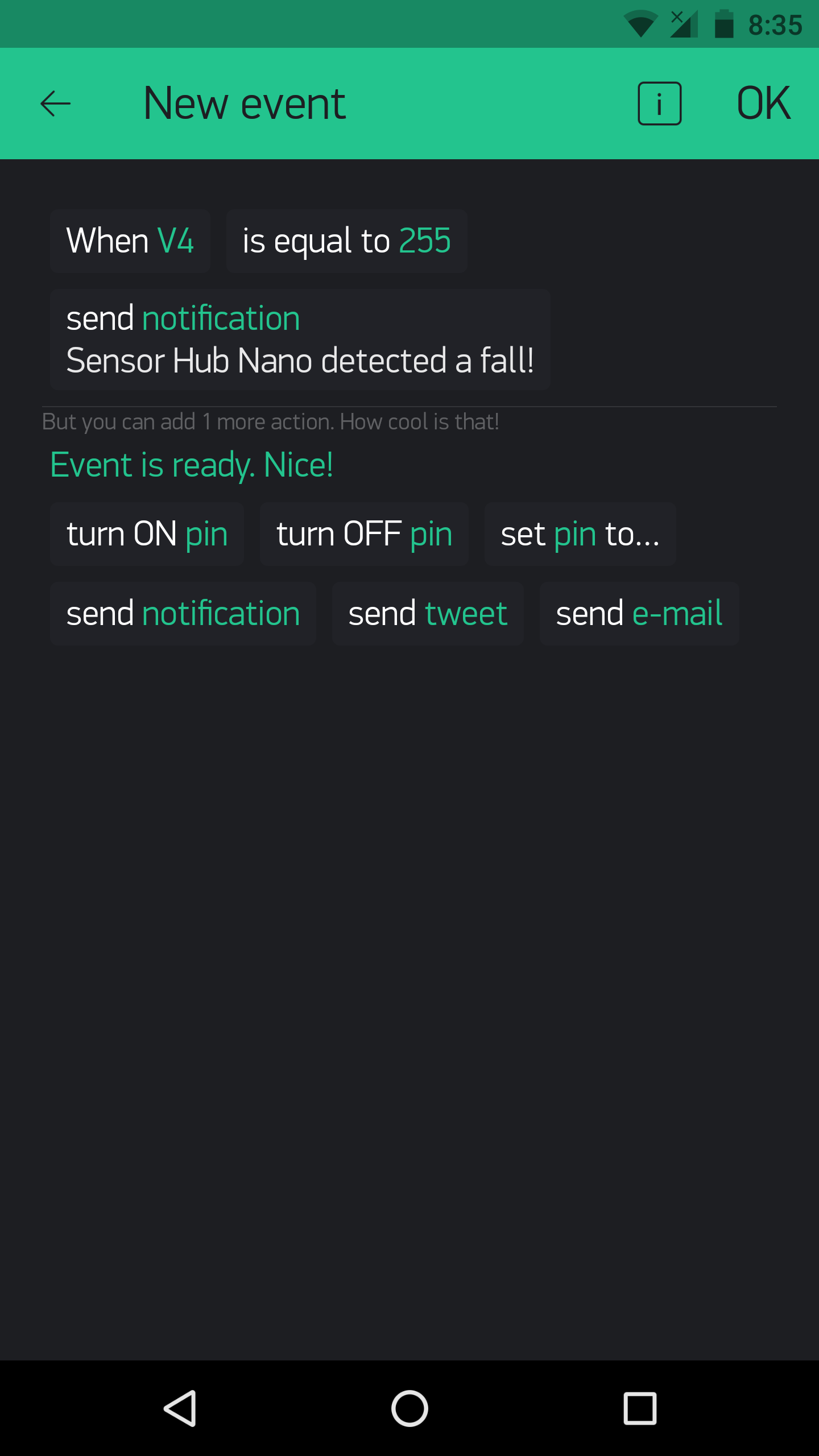
In the above example, the Eventor widget is used to set up a fall detection notification.
Using the Eventor widget to remind is done by this code:
BLYNK_WRITE(vEVENTOR_PIN) {
 //Use the Eventor widget to check if it's time to do a task (take medication in this case)
 int currentValue =param.asInt(); // 0 to 1
 if (currentValue ==1) {
 //Do here what you want to when its time for medication
 showPillReminder();
 playBuzzerReminder();
 //This is just a tone, I haven't made it in the main code, but you can if you want!
 }
 else {
 //If it's not the time for medication, do nothing
 }
}
And the result on the display when it's the time for medication:
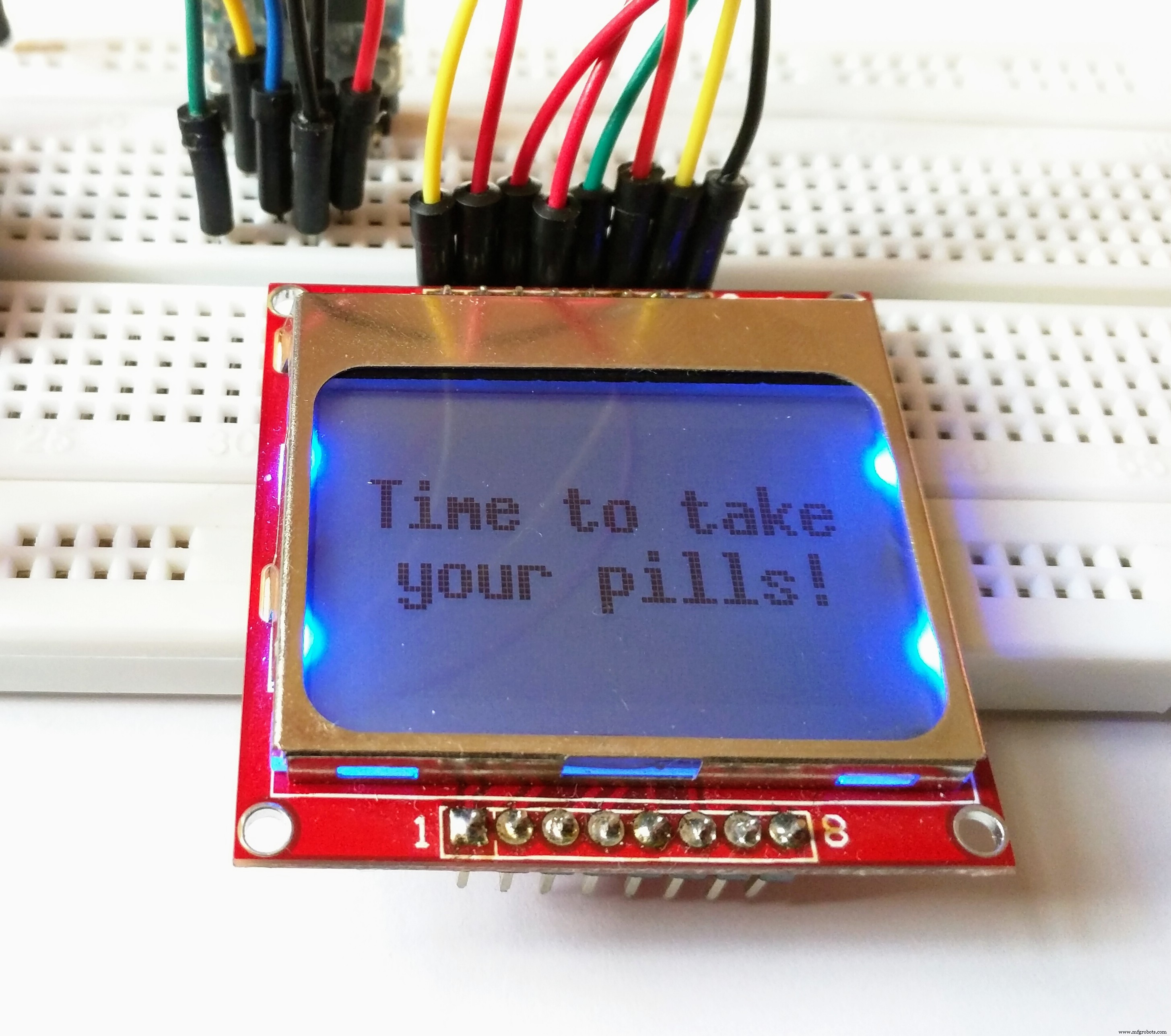
The same for exercise:
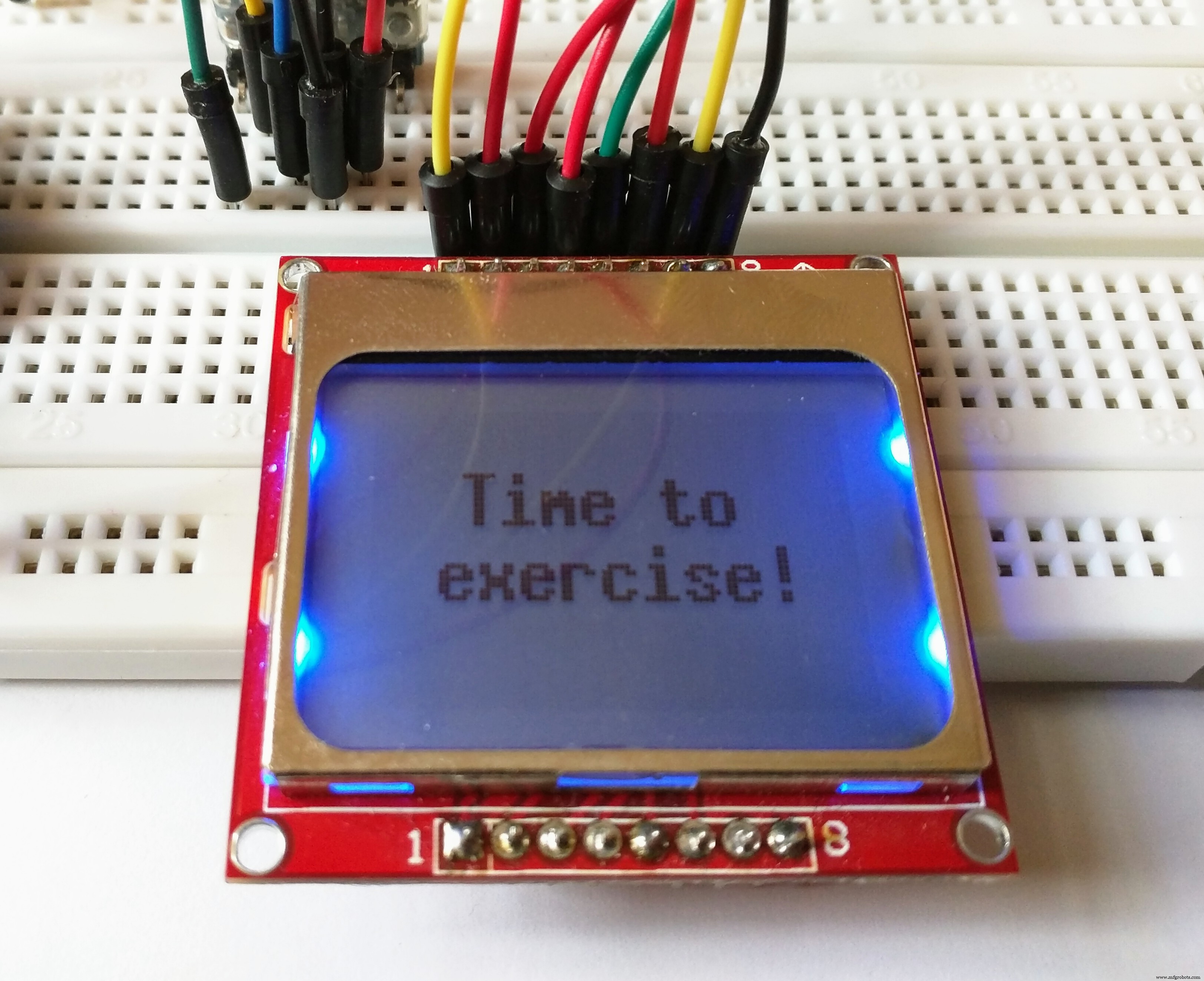
This is done by typing:
showExerciseReminder(); Instead of:
showPillReminder(); The eventor widget could, as said above, be used for a number of things. For example, you could set that an increase in temperature could result in sending an e-mail, and with no code modification!
Using different modes of the Sensor Hub Nano:-
You can test out the use of different modes for the Sensor Hub Nano. Using the following commands:
sendCommand(LOW_ENERGY);
sendCommand(STANDARD_MODE);
sendCommand(HIGH_PRECISION);
Using Blynk to switch modes could be more efficient. For that, set up your Blynk app like this:
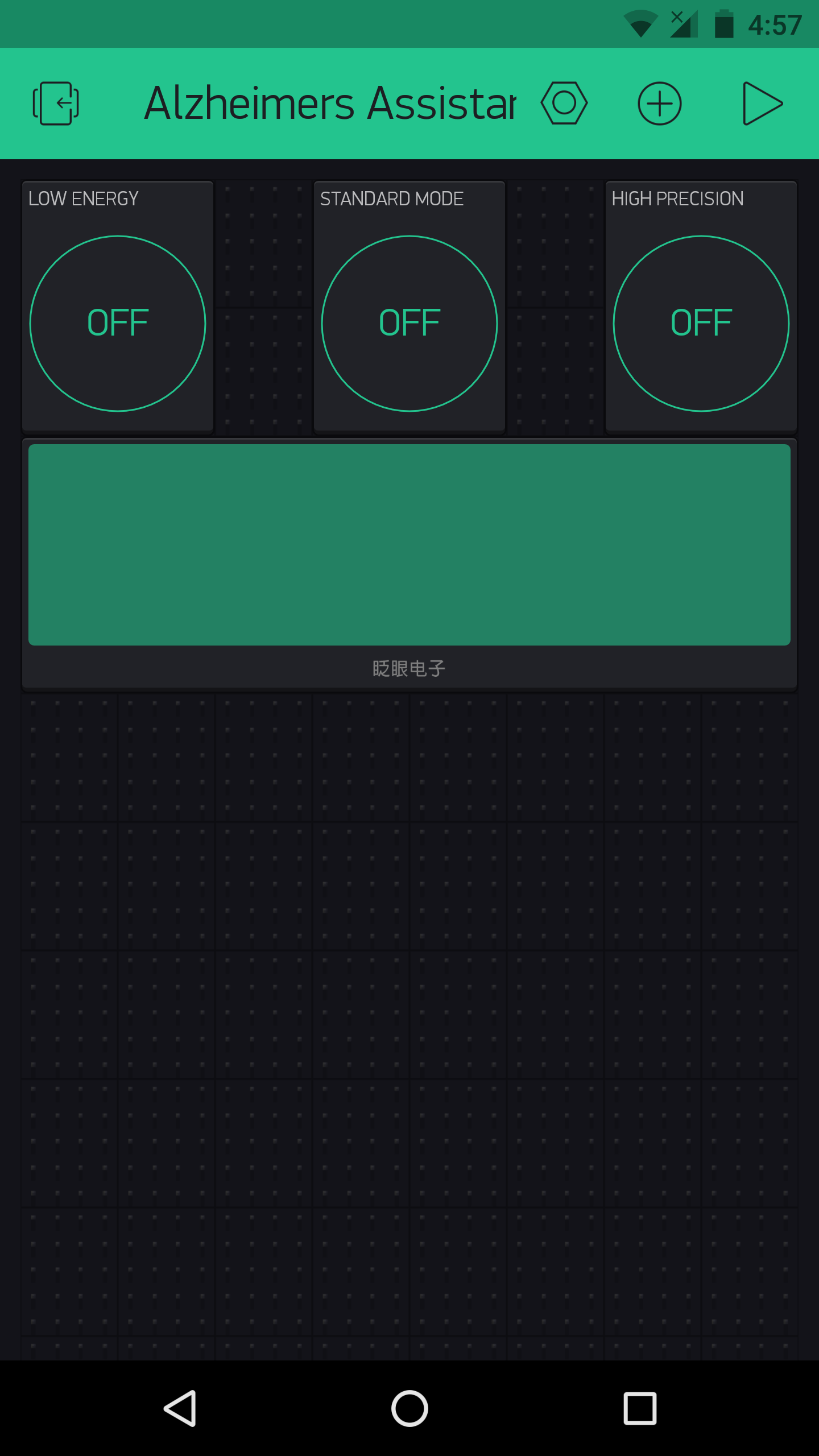
As this had no use for me, I did not add it it in the main code, but you could always do so as needed (The commands are present, you just need to add them with a bit of logic in the main sketch).
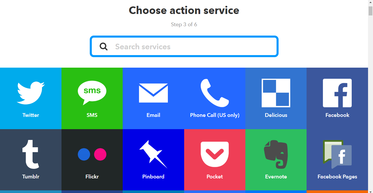
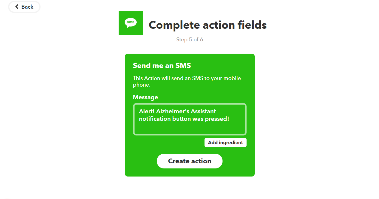
Using Blynk and IFTTT:-
Blynk can allow any Arduino project to easily harness the power of IFTTT.

This is because you can use Blynk to send a webhook request to the IFTTT Webhooks channel (previously called Maker channel), and you could create an IFTTT applet which waits for the webhook to be triggered (from the Blynk and Arduino side) and you could get it to trigger anything else in response to that.
A simple example on how to use IFTTT and Blynk with webhooks :
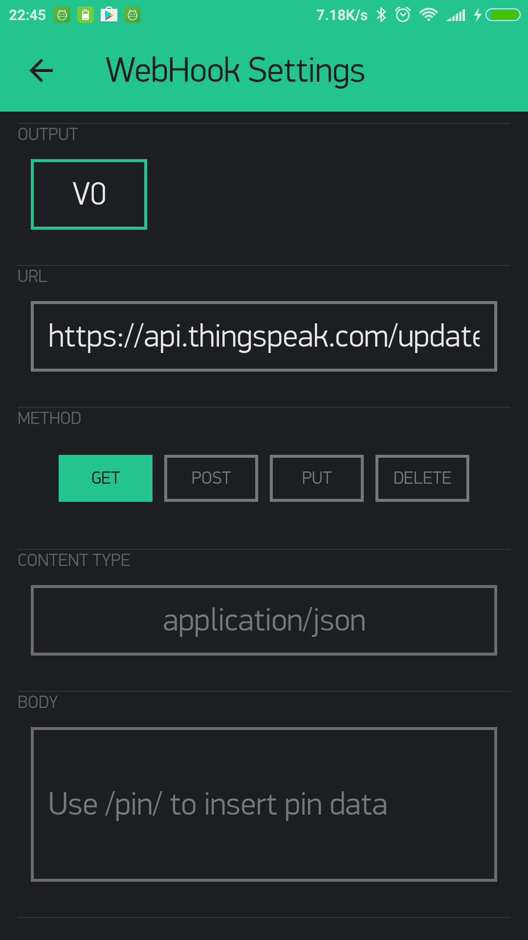
The Blynk webhook widget could be used to send a webhook request like this:
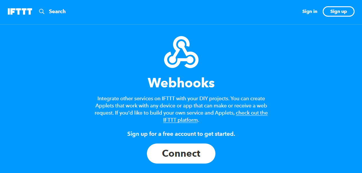
This is the IFTTT webhook channel:
And using webhooks to trigger IFTTT is not the only method. IFTTT can also be triggered by using Blynk to send emails and tweets.
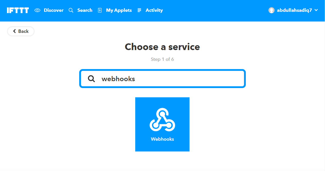
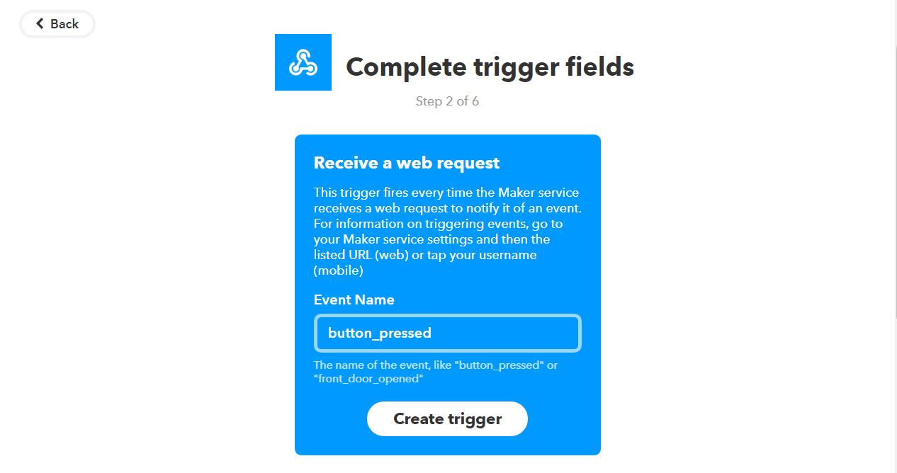
You have now made an applet. Time to test it.
Open "Services" in IFTTT and then select "Webhooks". Go to "Settings" and there you will see a URL. Copy that and open it in a new tab. There, instead of {event}, type the event name (which you set earlier). That was "button_pressed" for me, and so when I click on "Test it", this is the result after a few seconds:
Now that you have confirmed the Webhook works, you can just write the URL in the Blynk webhook settings and get a GET or POST request (through the Blynk webhook widget)
And, instead of SMS, you could just as well use phone calls, or even Twitter and Facebook, if you want, and it's just as simple That is the power of IFTTT.
It's the same thing as my smart home controller project here, and I also discussed it in detail there, but it is a great thing which I couldn't go by without mentioning.
Final Touches
By now, almost all of the electronics part of the project is complete, but a few things still remain. Read on for them, and in the end, I will list the future work which should be done to improve this project.
Battery and charging:
The MKR1000 has a port for a LiPo battery, which means you could attach one. But I don't have one at the moment so I will not be going into that but you should check out the website for the Arduino MKR1000 if you need information on that.
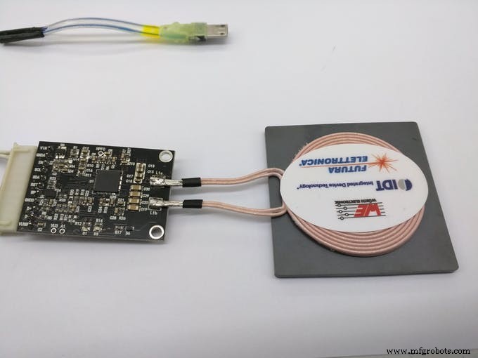
For charging, you have two options, using the MKR1000 USB port directly, and the other one is to use wireless charging, if you have it. I will be using the wireless charging for it. This is because I already have a wireless charging receiver and transmitter made by Futara Elettronica.
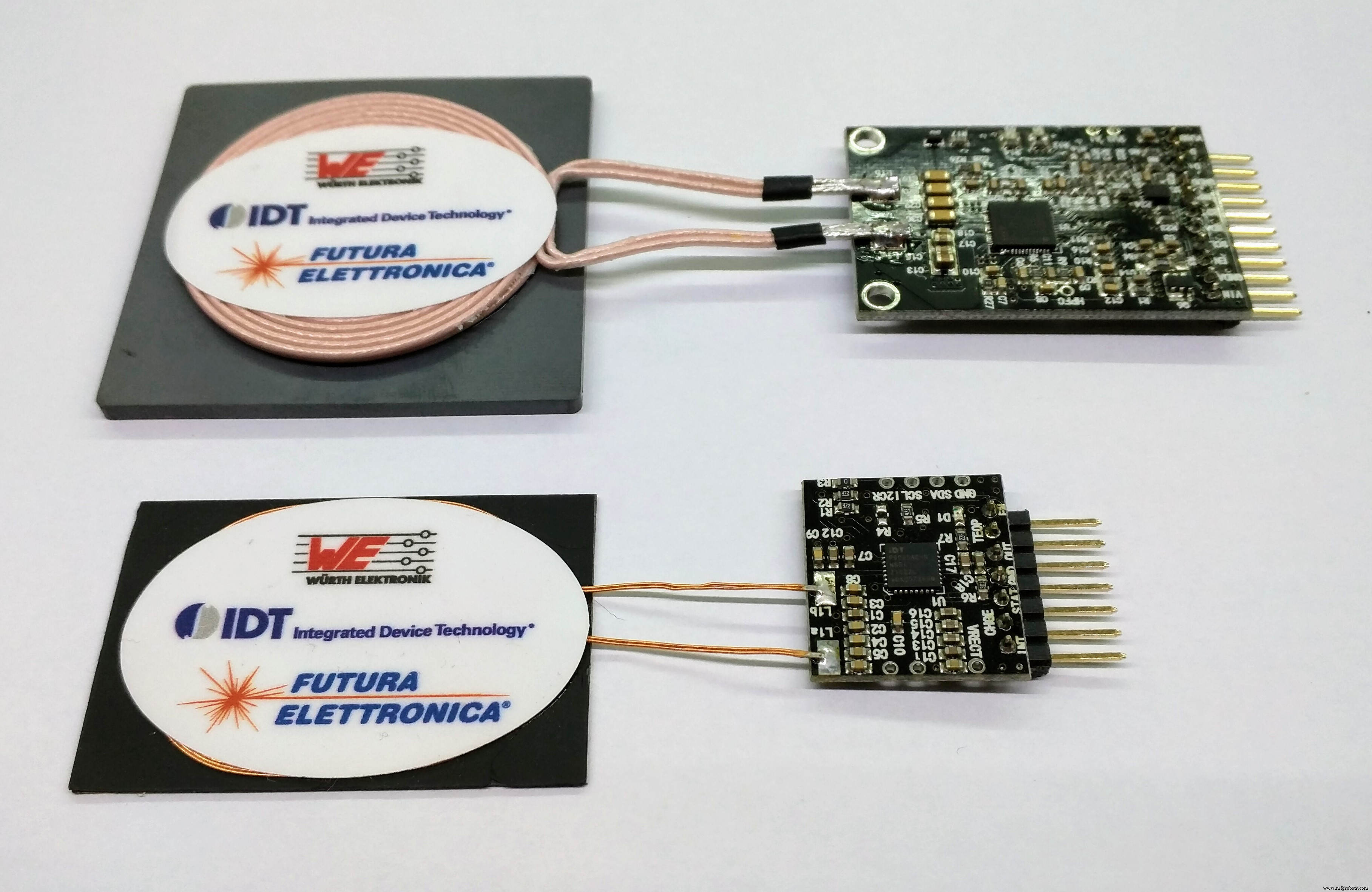
To use the receiver and transmitter, it's just a simple matter of providing the specified voltage to the transmitter. That will be the 'dock', where you can place Alzheimer's Assistant to charge. At the receiver side, you will just have to cut and attach a spare USB micro B cable (which goes to the MKR1000 USB port) and connect the other side to VCC and ground by looking at the pinout.
Just look at the images below to see how to wire it up:
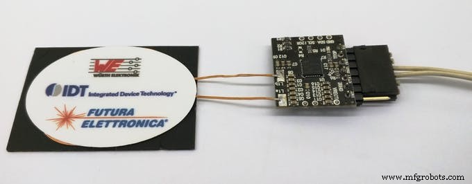
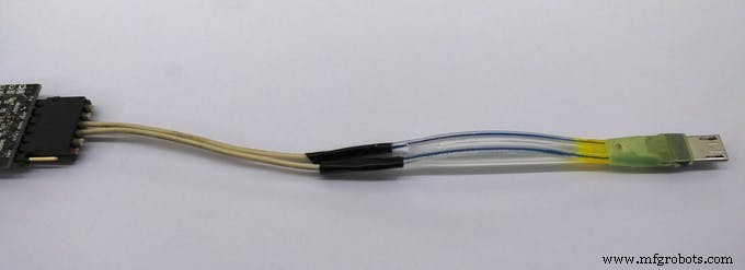
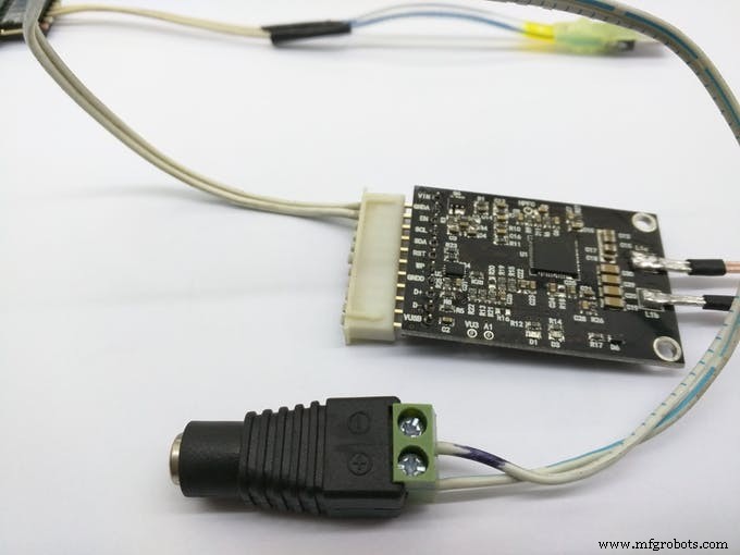
And the end result:
The Enclosure:
As with every project, an enclosure is required for this too, and this how I intend Alzheimer's Assistant to look like:
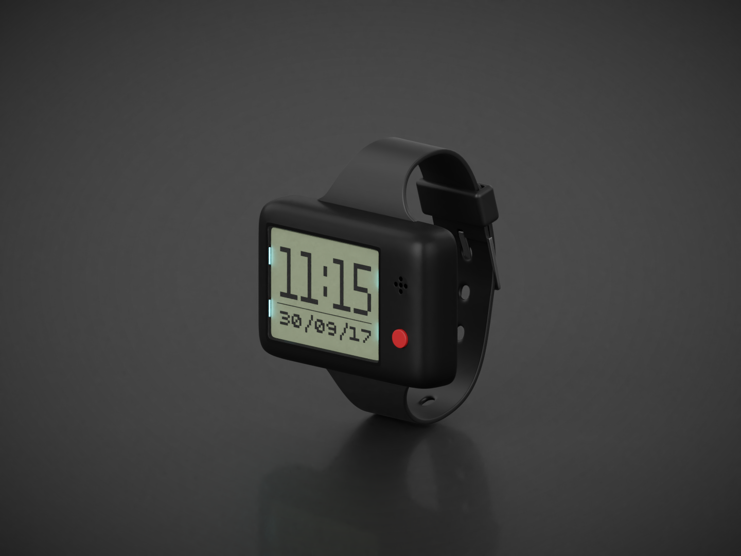
Note:I do not yet have the privilege of a laser cutter or 3D printer, so the STL file is just intended for showing how the final project looks like and it's not to scale.
This concludes the documentation for Alzheimer's Assistant, but I would still like to include the future work section to describe the things which I very much wanted to do for the project, but couldn't, due to some reason or the other.
Future work:
As I said before, these are the things which I wanted to include in the project, which I will add in future, should I get the time:
<울>Thanks for reading, and hope you liked my project. Feel free to give me your opinions and ideas about the project.
<섹션 클래스="섹션 컨테이너 섹션 축소 가능" id="코드">// Original sketch from Martyn Currey's blog here:// http://www.martyncurrey.com/arduino-with-hc-05-bluetooth-module-at-mode///// Sketch modified by me to work with Arduino MKR1000!//// Basic Bluetooth sketch// Connect the HC-05 module and communicate using the serial monitor//// The HC-05 defaults to commincation mode when first powered on.// Needs to be placed in to AT mode// After a factory reset the default baud rate for communication mode is 38400char c =' ';void setup() { // start the serial communication with the host computer Serial.begin(9600); Serial.println("Arduino with HC-05 is ready"); // start communication with the HC-05 using 38400 Serial1.begin(38400); Serial.println("Serial1 started at 38400");}void loop() { // Keep reading from HC-05 and send to Arduino Serial Monitor if (Serial1.available()) { c =Serial1.read(); Serial.write(c); } // Keep reading from Arduino Serial Monitor and send to HC-05 if (Serial.available()) { c =Serial.read(); // mirror the commands back to the serial monitor // makes it easy to follow the commands Serial.write(c); Serial1.write(c); }} //Including required libraries#include#include #include #include #include #include // You should get Auth Token in the Blynk App.// Go to the Project Settings (nut icon).char auth[] =""; //Enter your Blynk auth token here// Your WiFi credentials.// Set password to "" for open networks.char ssid[] ="";char pass[] ="";//Defining Sensor Hub Nano board commands#define HELLO "$hello id="#define INFO "$info id="#define SENSOR_INFO "$sinfo id=1"#define LOW_ENERGY "$set_mode sid=1;md=mode;val=bg"#define STANDARD_MODE "$set_mode sid=1;md=prs_osr;val=16"#define HIGH_PRECISION "$set_mode sid=1;md=prs_mr;val=32"#define START "$start_sensor id=1"#define STOP "$stop id="//Defining fall and clearance thresholds//You may need to change them, but I found these values to be good#define FALL 0.7#define CLEARANCE 0.2//Defining Blynk virtual pins#define vTEMPERATURE_PIN V0#define vPRESSURE_PIN V1#define vALTITUDE_PIN V2#define vEVENTOR_PIN V3#define vFALL_PIN V4//Declaring required variablesfloat t, p, a, previousA;//Boolean which tells tells if a fall is detected or notboolean fallState;//Variables needed for the fall detection algorithmunsigned long previousMillis =0;const long interv al =1000;//BTconnected is false when not connected and true when connectedboolean BTconnected =false;//Defining BT state and LCD backlight pinsint btStatePin =9;int backlightPin =2;BlynkTimer timer;WidgetRTC rtc;//Nokia 5110 Display wiringU8G2_PCD8544_84X48_F_4W_SW_SPI u8g2(U8G2_R0, /* clock=*/ 7, /* data=*/ 8, /* cs=*/ 3, /* dc=*/ 5, /* reset=*/ 4);void setup() { //Initialize both serial ports:Serial.begin(115200); Serial1.begin(115200); //Setup the timed fuctions timer.setInterval(1000L, sendSensorValues); timer.setInterval(3000L, showTimeAndDate); //Setting up required inputs and outputs pinMode(btStatePin, INPUT); pinMode(backlightPin, OUTPUT); digitalWrite(backlightPin, LOW); u8g2.begin(); showStartMessage(); 지연(2000); // wait until the bluetooth module has made a connection while (!BTconnected) { if (digitalRead(btStatePin) ==HIGH) { BTconnected =true; } else { showWaitingFor(); } } initSensorHub(); Blynk.begin(auth, ssid, pass); rtc.begin(); setBlynkWidgets(); showTimeAndDate(); sendCommand(START);}void loop() { Blynk.run(); timer.run(); getSensorValues(); checkIfFalling();}void sendCommand (String sensorCommand) { //This function sends commands through the bluetooth module on the hardware serial port to the the Sensor Hub Nano //For example:"sendCommand(START);", starts the flow of data from the sensor //The full list of commands I know are defined at the top of the sketch Serial1.println(sensorCommand);}void initSensorHub() { //Initialise the Sensor Hub Nano, and give an error if there is any problem String junkVal; sendCommand(INFO); while (Serial1.find("IFX_NanoHub") ==false) { sendCommand(INFO); Serial.println("ERROR"); showErrorMessage(); } junkVal =Serial1.readStringUntil('\n'); junkVal =""; showConnectedMessage(); delay(1500);}void getSensorValues() { //Retrieves the sensor values from the Sensor Hub Nano through the Serial1 port String junkVal; if (Serial1.available()) { junkVal =Serial1.readStringUntil('\n'); junkVal =Serial1.readStringUntil('t'); t =Serial1.parseFloat(); junkVal =Serial1.readStringUntil('p'); p =Serial1.parseFloat(); junkVal =Serial1.readStringUntil('a'); a =Serial1.parseFloat(); junkVal =Serial1.readStringUntil('\n'); }}void sendSensorValues() { //Sending the sensor values to the Blynk server Blynk.virtualWrite(vTEMPERATURE_PIN, t); Blynk.virtualWrite(vPRESSURE_PIN, p); Blynk.virtualWrite(vALTITUDE_PIN, a);}void checkIfFalling() { //Algorithm to check if the patient is falling unsigned long currentMillis =millis(); if ((currentMillis - previousMillis)>=interval) { float diff =previousA - a; if ((diff>=(FALL - CLEARANCE)) &&(diff <=(FALL + CLEARANCE))) { fallState =true; //Here insert what you need to do if fall is detected, such as sending a notification or email with Blynk //Or you could also use IFTTT to call or send an sms to alert the caretaker (more info in the project documentation) Serial.println("Falling"); showFallMessage(); //In this example, vFALL_PIN (virtual pin 4) is set to 255 if fall is detected Blynk.virtualWrite(vFALL_PIN, 255); //You can send a notification using only the notification widget too! //Blynk.notify("DPS310 detected a fall!"); } previousA =a; previousMillis =currentMillis; fallState =false; //Set vFALL_PIN to 0 if a fall isn't detected Blynk.virtualWrite(vFALL_PIN, 0); }}void showStartMessage() { //Shows the start-up message u8g2.clearBuffer(); u8g2.drawRFrame(3, 7, 75, 31, 7); u8g2.setFont(u8g2_font_prospero_bold_nbp_tf); u8g2.drawStr(8, 19, "Alzheimer's"); u8g2.drawStr(12, 35, "Assistant"); u8g2.sendBuffer();}void showWaitingFor() { //Shows the waiting for Sensor Hub Nano message u8g2.clearBuffer(); u8g2.setFont(u8g2_font_prospero_bold_nbp_tf); u8g2.drawStr(9, 15, "Waiting for"); u8g2.drawStr(8, 28, "Sensor Hub"); u8g2.drawStr(22, 41, "Nano !!!"); u8g2.sendBuffer();}void showConnectedMessage() { //Shows the connected message u8g2.clearBuffer(); u8g2.setFont(u8g2_font_7x13B_tf); u8g2.drawStr(0, 10, "Connected to"); u8g2.drawStr(8, 22, "Infineon's"); u8g2.drawStr(7, 34, "Sensor Hub"); u8g2.drawStr(29, 46, "Nano"); u8g2.sendBuffer();}void showErrorMessage() { //Shows the error message u8g2.clearBuffer(); // clear the internal memory u8g2.setFont(u8g2_font_fub14_tf); // choose a suitable font u8g2.drawStr(9, 30, "ERROR"); // write something to the internal memory u8g2.sendBuffer(); // transfer internal memory to the display}void showSensorValues() { //Shows the sensor values on the display char bufT[10]; char bufP[10]; char bufA[10]; String(t).toCharArray(bufT, 10); String(p).toCharArray(bufP, 10); String(a).toCharArray(bufA, 10); u8g2.clearBuffer(); u8g2.setFont(u8g2_font_6x10_tf ); //Display the temperature u8g2.drawStr(0, 10, "T:"); u8g2.drawStr(12, 10, bufT); u8g2.drawStr(73, 10, "C"); u8g2.drawCircle(70, 4, 1, U8G2_DRAW_ALL); u8g2.drawHLine(0, 12, 85); //Display the pressure u8g2.drawStr(0, 26, "P:"); u8g2.drawStr(12, 26, bufP); u8g2.drawStr(60, 26, "mBar"); u8g2.drawHLine(0, 28, 85); //Display the altitude u8g2.drawStr(0, 42, "A:"); u8g2.drawStr(12, 42, bufA); u8g2.drawStr(72, 42, "m"); u8g2.drawHLine(0, 44, 85); //Send the values to the display u8g2.sendBuffer();}void showFallMessage() { //Show the fall detected message u8g2.clearBuffer(); u8g2.setFont(u8g2_font_7x13B_tf); u8g2.drawStr(27, 20, "Fall"); u8g2.drawStr(13, 32, "Detected!"); u8g2.sendBuffer(); delay(1000);}void showPillReminder() { //Show the pill reminder message u8g2.clearBuffer(); u8g2.setFont(u8g2_font_7x13B_tf); u8g2.drawStr(0, 20, "Time to take"); u8g2.drawStr(5, 32, "your pills!"); u8g2.sendBuffer();}void showExerciseReminder() { //Show the exercise reminder message u8g2.clearBuffer(); u8g2.setFont(u8g2_font_7x13B_tf); u8g2.drawStr(16, 20, "Time to"); u8g2.drawStr(12, 32, "exercise!"); u8g2.sendBuffer();}void showTimeAndDate() { //Displays the time and date from the RTC widget in Blynk in 24 hours format if (year() ==1970) { //Serial.println("Time not yet synced"); } else if (year() !=1970) { char bufHours[3]; char bufColon[2]; char bufMinutes[3]; char bufDate[11]; String currentHours =String(hour()); String colon =":"; String currentMinutes =String(minute()); String currentDate =String(day()) + "/" + month() + "/" + year(); String(currentHours).toCharArray(bufHours, 3); String(colon).toCharArray(bufColon, 2); String(currentMinutes).toCharArray(bufMinutes, 3); String(currentDate).toCharArray(bufDate, 11); u8g2.clearBuffer(); u8g2.setFont(u8g2_font_inr33_mf); u8g2.drawStr(30, 30, bufColon); u8g2.setFont(u8g2_font_logisoso32_tn); u8g2.drawStr(0, 32, bufHours); u8g2.drawStr(45, 32, bufMinutes); u8g2.setFont(u8g2_font_saikyosansbold8_8n); u8g2.drawHLine(0, 35, 85); u8g2.drawStr(0, 46, bufDate); u8g2.sendBuffer(); }}BLYNK_WRITE(vEVENTOR_PIN) { //Use the Eventor widget to check if it's time to do a task (take medication in this case) int currentValue =param.asInt(); // 0 to 1 if (currentValue ==1) { showPillReminder(); //Serial.println("Time to take your pills"); } else { //Serial.println("Not the time to take pills"); }}void setBlynkWidgets() { //This sets the colour of each widget in the Blynk app //You may remove this from the sketch if you want to set colours manually through the Blynk app //You could also specifiy the hex value of each colour you need //Set temperature widget color to white Blynk.setProperty(vTEMPERATURE_PIN, "color", "#FFFFFF"); //Set pressure widget color to blue Blynk.setProperty(vPRESSURE_PIN, "color", "#00BBFF"); //Set altitude widget color to yellow Blynk.setProperty(vALTITUDE_PIN, "color", "#FFFF00");}BLYNK_CONNECTED() { //Synchronize time on connection, if connection drops rtc.begin();}
 Fritzing diagram for the bare-bones project to function
 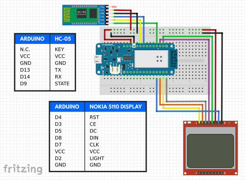 Document listing AT commands for the HC-05
제조공정
구성품 및 소모품 Arduino UNO × 1 브레드보드(일반) × 1 초음파 센서 - HC-SR04(일반) × 1 부저 × 1 LED(일반) × 3 저항 221옴 × 1 점퍼 와이어(일반) × 10 이 프로젝트 정보 1단계:자료 수집 2단계:설정 Arduino의 5V 핀에서 빨간색 와이어를 브레드보드의 양극 채널에 연결합니다. Arduino의 GND 핀에서
구성품 및 소모품 Arduino UNO × 1 Adafruit RGB 백라이트 LCD - 16x2 × 1 브레드보드(일반) × 1 저항 220옴 × 1 SparkFun 푸시버튼 스위치 12mm × 1 점퍼 와이어(일반) × 1 USB-A-B 케이블 × 1 앱 및 온라인 서비스 Arduino IDE 이 프로젝트 정보 필요한 부품은 위의 그림과