

제조공정

산업 제조
 |
| × | 1 | |||
 |
| × | 1 | |||
 |
| × | 4 | |||
 |
| × | 1 | |||
 |
| × | 2 | |||
 |
| × | 3 | |||
 |
| × | 4 | |||
 |
| × | 2 | |||
 |
| × | 1 | |||
 |
| × | 1 |
 |
| |||
 |
|
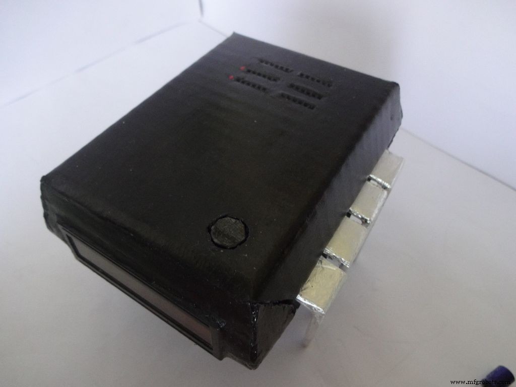

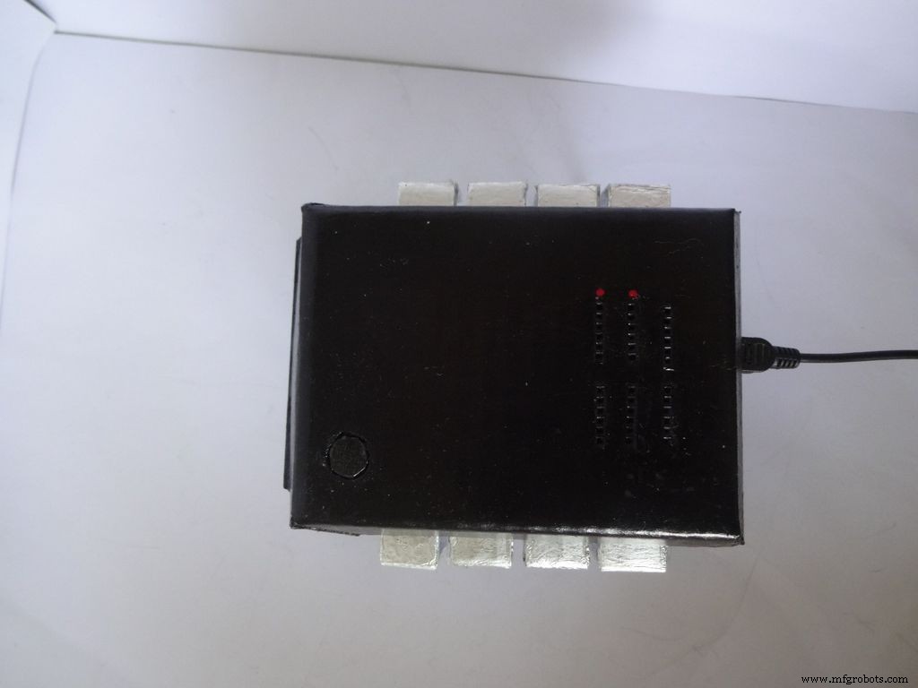
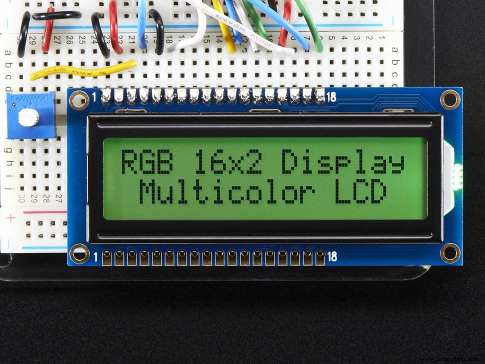
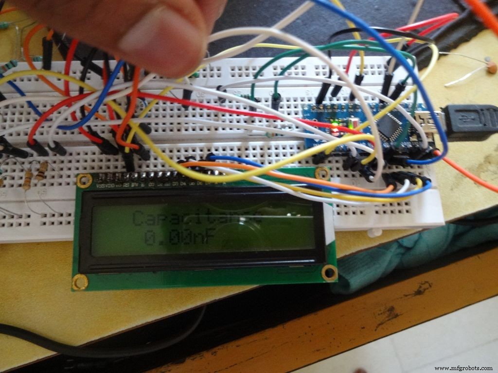
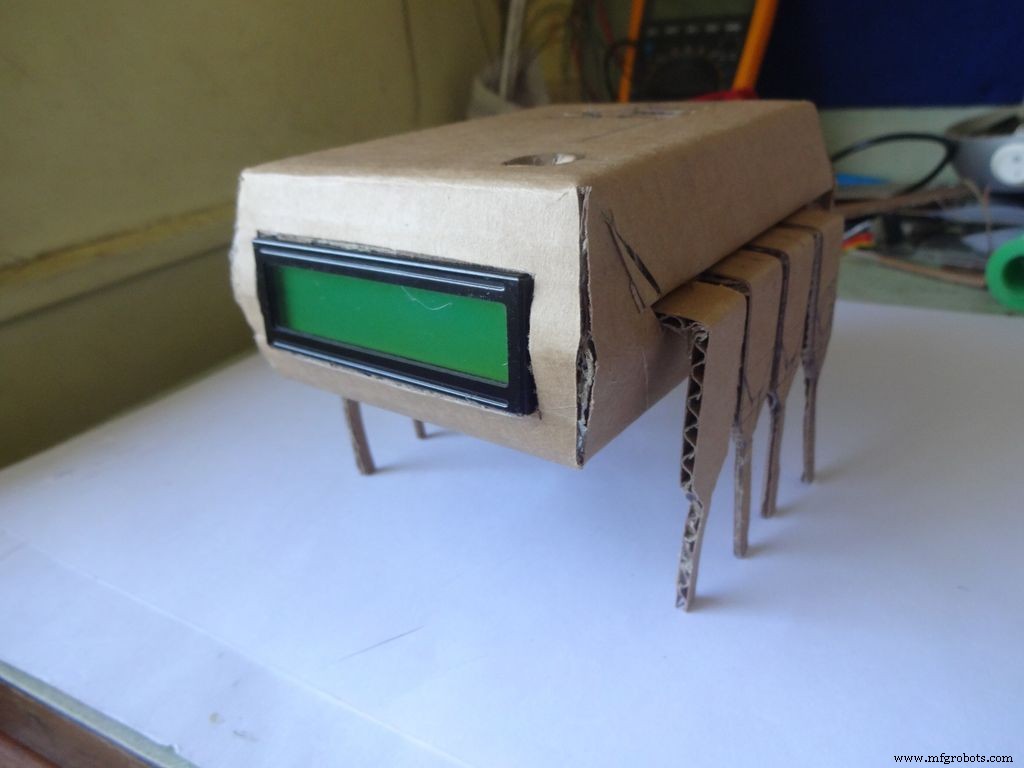
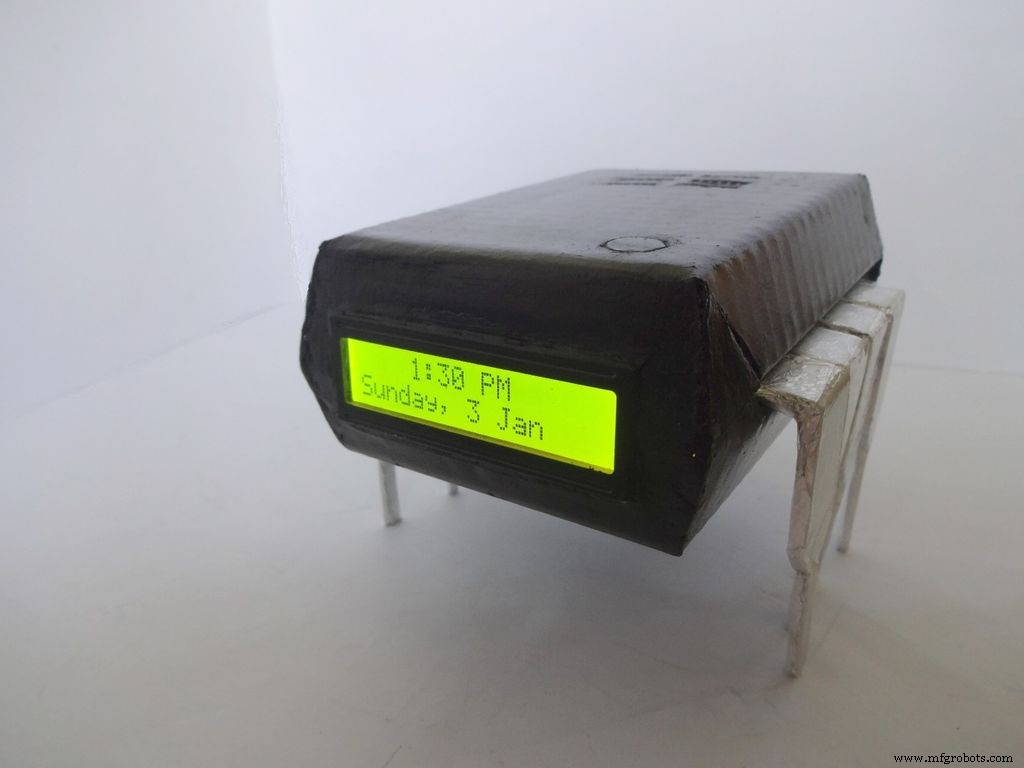
Companion IC는 매우 멋진 시계 + 저항계 + 커패시턴스 미터 + 다이오드 테스터입니다! IC의 핀 1을 눌러 켜십시오! 구성 요소를 빠르게 테스트하고 시간을 확인하려면 이것을 작업대에 보관하십시오. 작업대 근처에 전원이 있는 경우 배터리 또는 USB로 실행할 수 있습니다.
나는 항상 프로젝트를 게시하고 싶었지만 지금까지 만들 독특한 것을 찾지 못했습니다! 커패시터에 결함이 있는지 여부를 확인하기 위해 일부 커패시터를 테스트하고 싶을 때 아이디어가 떠올랐습니다. 나는 멀티 미터 만 사용할 수 있었고 정전 용량 측정 기능이 없었습니다. 검색해보니 아두이노로도 가능하다는 것을 알게 되었습니다. 하나 만들기로 결정했지만 Arduino에서 사용하지 않는 핀을 보는 것이 그다지 만족스럽지 않았기 때문에 자동 범위 저항계, 빠른 LED/다이오드 테스터 및 RTC 시계도 추가하기로 결정했습니다! 또한 프로브를 사용하지 않고 구성 요소를 연결하여 값을 직접 측정하기를 원했습니다. 디자인은 독특해야 했기 때문에 약간의 브레인스토밍 끝에 IC 디자인이 만들어졌습니다!
편집(2016/07/01) :선택적 연속성 테스트가 추가되었습니다. 댓글 섹션을 참조하세요.
이 기사는 내가 이것을 어떻게 만들고 당신도 그것을 스스로 만들 수 있는지에 대해 아주 자세히 설명합니다. 초보자에게 친숙하며 Arduino/전자 공학 경험이 2-3주 있으면 누구나 구축할 수 있습니다!
디자인은 수정 가능하며 요구 사항에 따라 새로운 기능을 제거/추가할 수 있습니다. 저는 판지로 케이스를 만들었는데 스킬만 있다면 나무로 하셔도 되고 3D프린터로 출력하셔도 됩니다.
나는 내가 한 모든 단계에서 사진을 찍고 첨부하려고했습니다 (각 단계에서 많이!). 이 중 대부분은 최상의 각도/조명을 얻을 때까지 여러 번 촬영되었지만 여전히 일부는 두 손으로 모두 잡기가 힘들기 때문에 약간 흐릿합니다.
나는 전체 코드와 배선을 내가 만든 방식대로 조각과 단계로 나누었습니다. 포함된 코드는 주석이 많고 적절하게 들여쓰기되어 있습니다. 계속 진행하면서. 우리는 모든 코드와 배선을 단계적으로 결합하여 최종 IC를 만들 것입니다. 이것은 누군가가 그것을 명확하게 이해하는 데 도움이 될 것입니다. 그렇지 않다면 댓글로 알려주세요.
만들지 않기로 결정했더라도 브레드보드에서 시도하거나 적어도 한 번은 여기에서 배울 수 있고 언젠가는 사용할 수 있는 방법이나 트릭 또는 뭔가가 있을 것입니다(진심, 언제 사용할지 모릅니다. 클릭!)
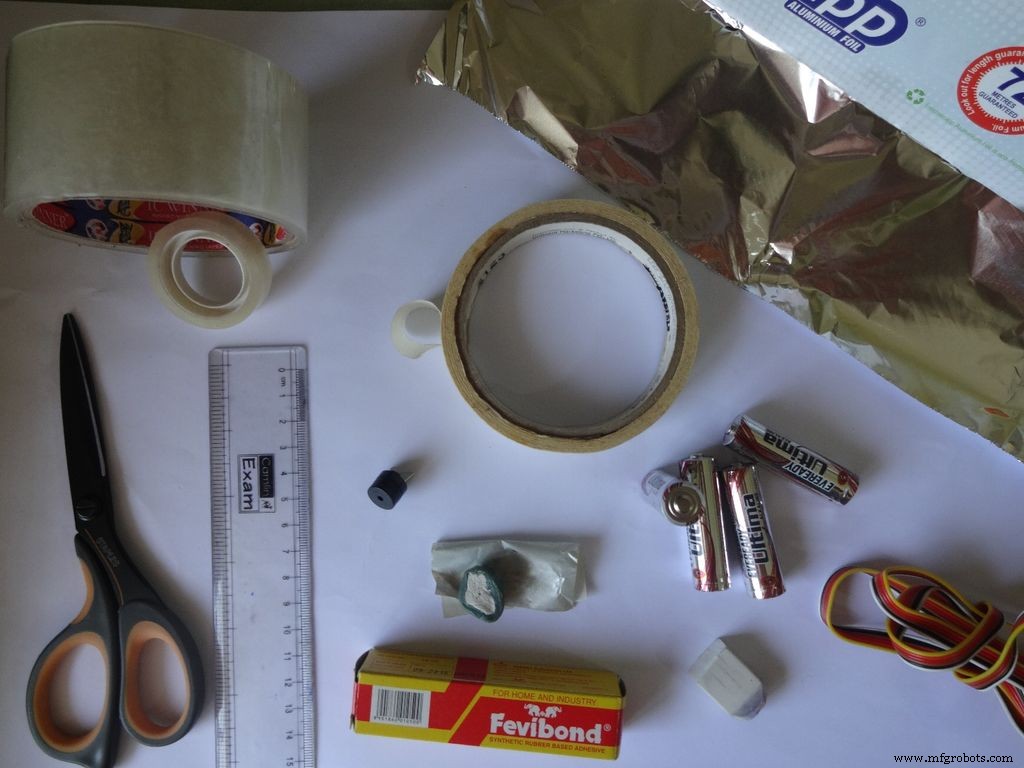
1단계:필요한 도구 및 구성 요소
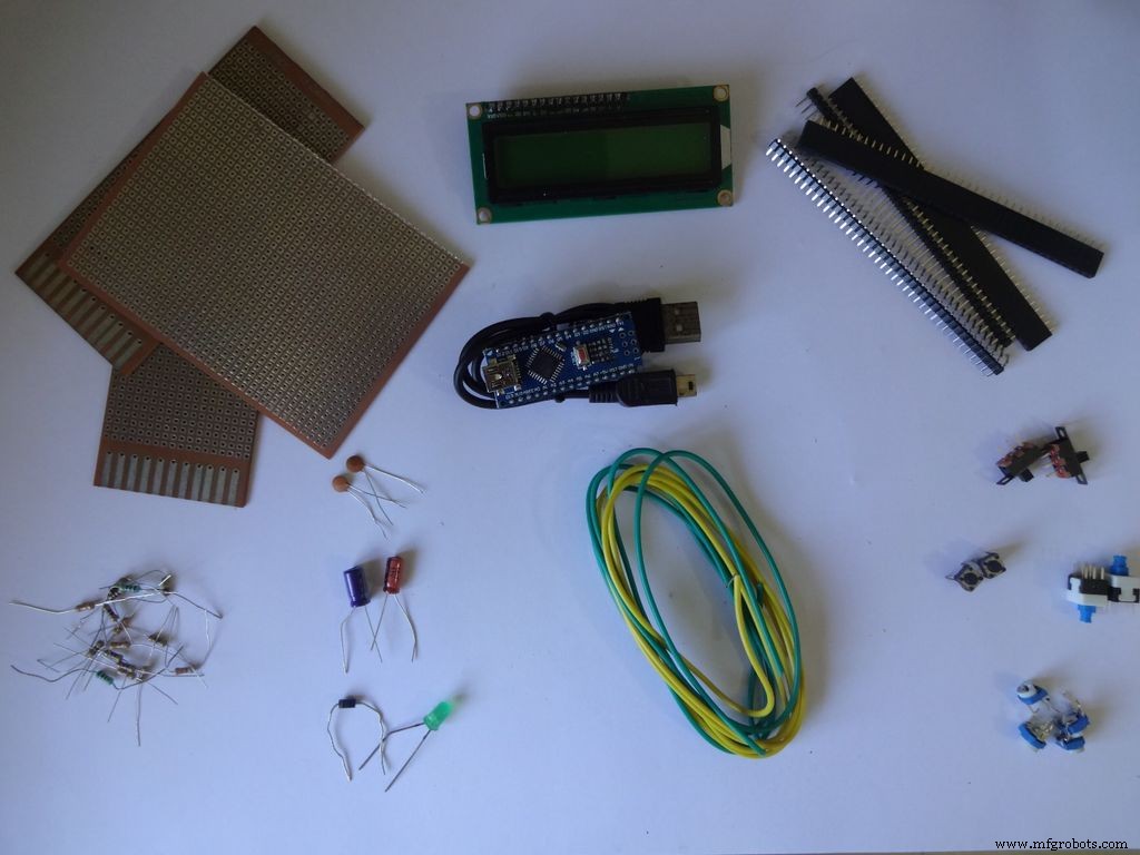

사용된 구성 요소 및 재료 목록(참고용으로만 링크 저장):
<울>필요한 도구:
<울>
2단계:저항계 - 개념
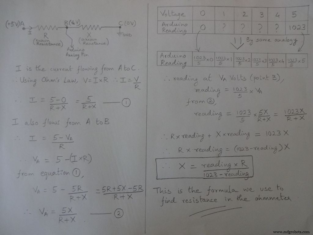
저항 측정의 기본 개념은 전압 분배기에서 나옵니다.
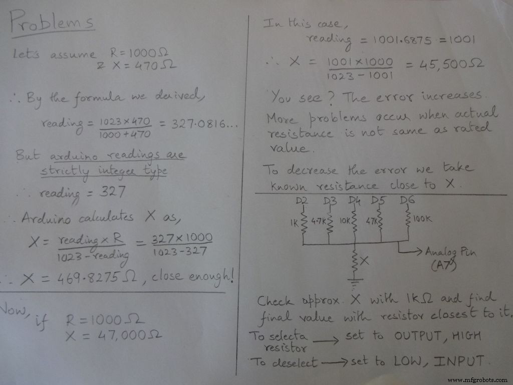
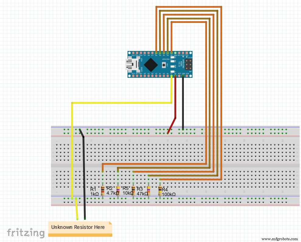
저항 값은 수정 가능하며 r1, r2 등의 값을 변경합니다. 또한 그에 따라 범위(자동 범위 설정의 경우)를 설정합니다. 아래 코드를 참조하고 끝에 있는 파일에서 다운로드하고 브레드보드에서 저항계를 테스트합니다.
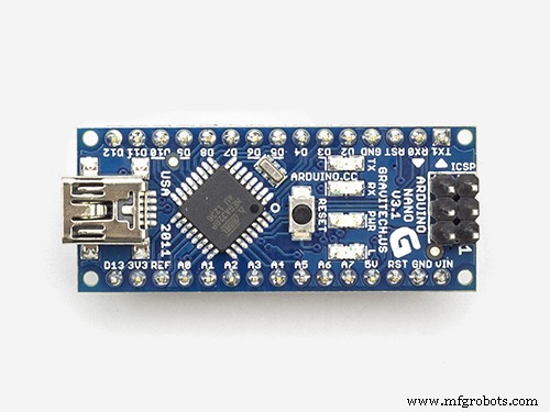
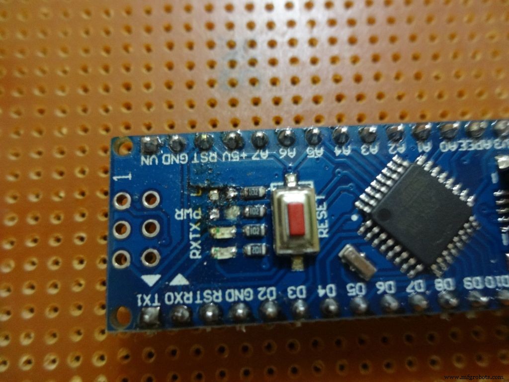
Nano를 처음 설정하는 경우 여기에서 CH340G 드라이버를 다운로드할 수 있으며 Windows 7, 8, 8.1 및 10에서 작동합니다. Mac 사용자는 여기에서 확인하십시오.
보드 메뉴에서 "Arduino Nano"를 선택하고 올바른 COM 포트를 선택하십시오. 업로드!
코드
//저항을 찾는 데 사용되는 아날로그 핀int Apin=7;//r1에서 r5까지의 값float r1=1000;float r2=4700;float r3=10000;float r4=47000;float r5=100000;/ /r1에서 r5까지의 핀 r1_pin=2;int r2_pin=3;int r3_pin=4;int r4_pin=5;int r5_pin=6;float 판독=0; //아날로그 핀에서 읽고 herefloat R=0을 저장합니다. //알 수 없는 것을 계산하고 hereString을 저장합니다. finalR; //unitsint caseno와 함께 표시될 최종 값; //디버깅을 위해 케이스 번호를 저장합니다. // 전체 범위를 케이스로 나누고 각각에 총 5개의 케이스를 할당합니다. // case1 :2850 미만 // case2 :2850 ~ 7350 // case3 :7350 ~ 28500 // case4 :28500 to 73500 // case5 :more than 73500#include // float를 string으로 변환하는데 필요, String(float,n) 함수가 있다. 아래에 설명되어 있습니다.void setup() { Serial.begin(9600);}void loop() { //먼저 1kOhm 저항을 사용하여 알 수 없는 저항을 찾습니다. //따라서 R2, R3, R4 및 R5를 비활성화합니다. digitalWrite(r2_pin, LOW); // INPUT pinMode(r2_pin, INPUT)로 설정하기 전에 각 핀을 LOW로 설정합니다. // HIGH가 내부 풀업 저항을 활성화할 때 INPUT으로 설정합니다. digitalWrite(r3_pin, LOW); 핀모드(r3_pin, 입력); digitalWrite(r4_pin, LOW); 핀모드(r4_pin, 입력); digitalWrite(r5_pin, LOW); 핀모드(r5_pin, 입력); 핀모드(r1_pin, 출력); digitalWrite(r1_pin, HIGH); //저항을 읽고 계산합니다. reading=analogRead(Apin); R=(판독*r1)/(1023-판독); // 값 <2850이면 finalR =값(1kOhm 사용) if(R<2850){ caseno=1; if(R<1000){ //값이 1000보다 작으면 "kOhm"이 아닌 "Ohm"을 사용합니다. finalR =String(R,2) + "Ohm"; //String(float,n) float를 소수점 이하 n자리의 문자열로 변환 // 문자열에 값 뒤에 "Ohm"을 붙이고 '+'는 여기에 두 문자열을 결합합니다. } else{ //use "kOhm R=R/1000; finalR =String(R,2) + "kOhm"; } } //값이 2850과 7350 사이이면 4.7kOhm에서 얻은 값을 사용합니다. else if(R>=2850 &&R<7350){ caseno=2; digitalWrite(r1_pin , LOW); //4.7kOhm만 활성화 핀모드(r1_pin, INPUT); digitalWrite(r3_pin, LOW); pinMode(r3_pin, INPUT); digitalWrite(r4_pin, LOW); pinMode(r4_pin, INPUT); digitalWrite(r5_pin, LOW) ), pinMode(r5_pin, INPUT), pinMode(r2_pin, OUTPUT), digitalWrite(r2_pin, HIGH), reading=analogRead(Apin), R=(reading*r2)/(1023-reading)/1000, finalR =String( R,2) + "kOhm"; } //값이 7350과 28500 사이이면 10kOhm에서 얻은 값 사용 else if(R>=7350 &&R<28500){ caseno=3; digitalWrite(r1_pin, LOW); pinMode( r1_pin, INPUT); digitalWrite(r2_pin, LOW); pinMode(r2_pin, INPUT); digitalWrite(r4_pin, LOW); pinMode(r4_pin, INPUT); digitalWrite(r5_pin, LOW); pinMode(r5_pin, INPUT); pinM ode(r3_pin, 출력); 디지털 쓰기(r3_pin, 높음); 읽기=analogRead(Apin); R=(판독*r3)/(1023-판독)/1000; finalR=문자열(R,2) + "kOhm"; } //값이 28500에서 73500 사이이면 47kOhm에서 얻은 값을 사용합니다. else if(R>=28500 &&R<73500){ caseno=4; digitalWrite(r1_pin, LOW); 핀모드(r1_pin, 입력); digitalWrite(r2_pin, LOW); 핀모드(r2_pin, 입력); digitalWrite(r3_pin, LOW); 핀모드(r3_pin, 입력); digitalWrite(r5_pin, LOW); 핀모드(r5_pin, 입력); 핀모드(r4_pin, 출력); digitalWrite(r4_pin, HIGH); 읽기=analogRead(Apin); R=(판독*r4)/(1023-판독)/1000; finalR =문자열(R,2) + "kOhm"; } //값이 73500보다 크면 100kOhm에서 얻은 값을 사용 else if(R>=73500){ caseno=5; digitalWrite(r1_pin, LOW); 핀모드(r1_pin, 입력); digitalWrite(r2_pin, LOW); 핀모드(r2_pin, 입력); digitalWrite(r3_pin, LOW); 핀모드(r3_pin, 입력); digitalWrite(r4_pin, LOW); 핀모드(r4_pin, 입력); 핀모드(r5_pin, 출력); digitalWrite(r5_pin, HIGH); 읽기=analogRead(Apin); R=(판독*r5)/(1023-판독)/1000; finalR =문자열(R,2) + "kOhm"; } 직렬.println(최종R); //최종 문자열을 단위로 출력하기 Serial.println(" "); 지연(1000);}
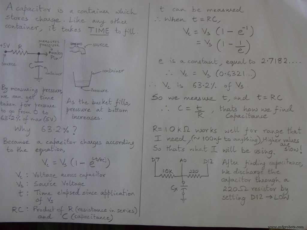
3단계:정전용량 측정기 - 개념

코드
/* RCTiming_capacitance_meter * Paul Badger 2008에서 가져온 코드 개념 * * 한 시간 상수에서 커패시터의 전압은 충전 전압의 63.2%로 정의됩니다. * 즉, A 커패시터는 1 시간 상수에서 전체 용량의 63.2%로 채워집니다. */ int analogPin=0; // 커패시터 전압을 측정하기 위한 아날로그 핀 int chargePin=7; // 커패시터를 충전하기 위한 핀 - 충전 저항의 한쪽 끝에 연결 int dischargePin=12; // 다이오드 테스트(chechPin1)에 사용된 것과 동일한 커패시터를 방전하기 위한 핀 float resistorValue=10000.0; // 10kOhm 저항기 unsigned long startTime을 사용합니다. 서명되지 않은 긴 경과 시간; 플로트 마이크로패럿; // 정밀도를 유지하기 위한 부동 소수점 변수, 계산을 float nanoFarads;void setup(){ pinMode(chargePin, OUTPUT); // ChargePin을 출력으로 설정합니다. digitalWrite(chargePin, LOW); Serial.begin(9600); // 디버깅을 위한 직렬 전송 초기화}void loop(){ digitalWrite(chargePin, HIGH); // ChargePin을 HIGH로 설정하고 커패시터 충전 startTime =millis(); while(analogRead(analogPin) <648){ // 647은 1023의 63.2%로 전체 전압에 해당합니다. } elapsedTime=millis() - startTime; // 밀리초를 초로 변환( 10^-3 ) 및 패럿을 마이크로패럿으로 변환( 10^6 ), net 10^3 (1000) microFarads =((float)elapsedTime / resistorValue) * 1000; // (float) "unsigned long" 경과 시간을 float로 변환합니다. Serial.print(elapsedTime); // 직렬 포트에 값을 출력합니다. Serial.print(" mS "); // 인쇄 단위 if (microFarads> 1){ Serial.print((long)microFarads); // 직렬 포트에 값을 출력합니다. Serial.println(" microFarads"); // 인쇄 단위 } else { // 값이 1 microFarad보다 작으면 nanoFarad(10^-9 Farad)로 변환합니다. 나노패럿 =마이크로패럿 * 1000.0; // nanoFarads로 변환하려면 1000을 곱합니다. (10^-9 Farads) Serial.print((long)nanoFarads); // 직렬 포트에 값을 출력합니다. Serial.println(" nanoFarads"); // 인쇄 단위 } /* 커패시터 방전 */ digitalWrite(chargePin, LOW); // 충전 핀을 LOW로 설정합니다. pinMode(dischargePin, OUTPUT); // 방전 핀을 출력으로 설정 digitalWrite(dischargePin, LOW); // 방전 핀을 LOW로 설정 while(analogRead(analogPin)> 0){ // 커패시터가 완전히 방전될 때까지 대기 } pinMode(dischargePin, INPUT); // 방전 핀을 다시 입력으로 설정}
4단계:다이오드 테스트
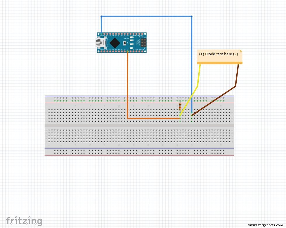
아날로그 핀은 10k Ohm 저항으로 최대 5V로 풀링됩니다. 따라서 아날로그 핀은 1023을 읽습니다. 아무것도 연결되어 있지 않을 때. D12 OUTPUT으로 설정됨 , 낮음 .
다이오드가 아날로그 핀 사이에 순방향 바이어스되는 경우 (5V ) 및 D12 (GND ), 아날로그 핀 100-400 읽기 .
역 바이어스되면 실제로 매우 작은 전류가 흐르고 아날로그 핀 900-1023을 읽습니다. .
이런 식으로 우리는 모든 다이오드의 p와 n 쪽을 간단히 찾을 수 있습니다. LED 및 다이오드를 빠르게 확인하는 데 사용할 수 있습니다.
코드
문자열 상태 ="null";int checkPin1 =12;int checkPin2 =6;void setup() { Serial.begin(9600);}void 루프() {pinMode(checkPin1, OUTPUT); digitalWrite(checkPin1, LOW); //핀 11은 로우로 설정됨 // 아날로그 읽기는 일반적으로 10k 저항에 의해 풀업되므로 널 읽기는 1023입니다. // 순방향 바이어스에서 아날로그 핀은 LOW인 checkPin1에 연결됩니다. 따라서 1023보다 작은 값을 읽는 경우//역방향 바이어스에서도 실제로 작은 전류가 흐르므로 700을 사용하여 구별합니다. if(analogRead(checkPin2)<700){ state="forward"; } 직렬.println(상태); Serial.println(analogRead(checkPin2)); 상태 ="널"; 지연(500);}
5단계:실시간 시계(RTC)
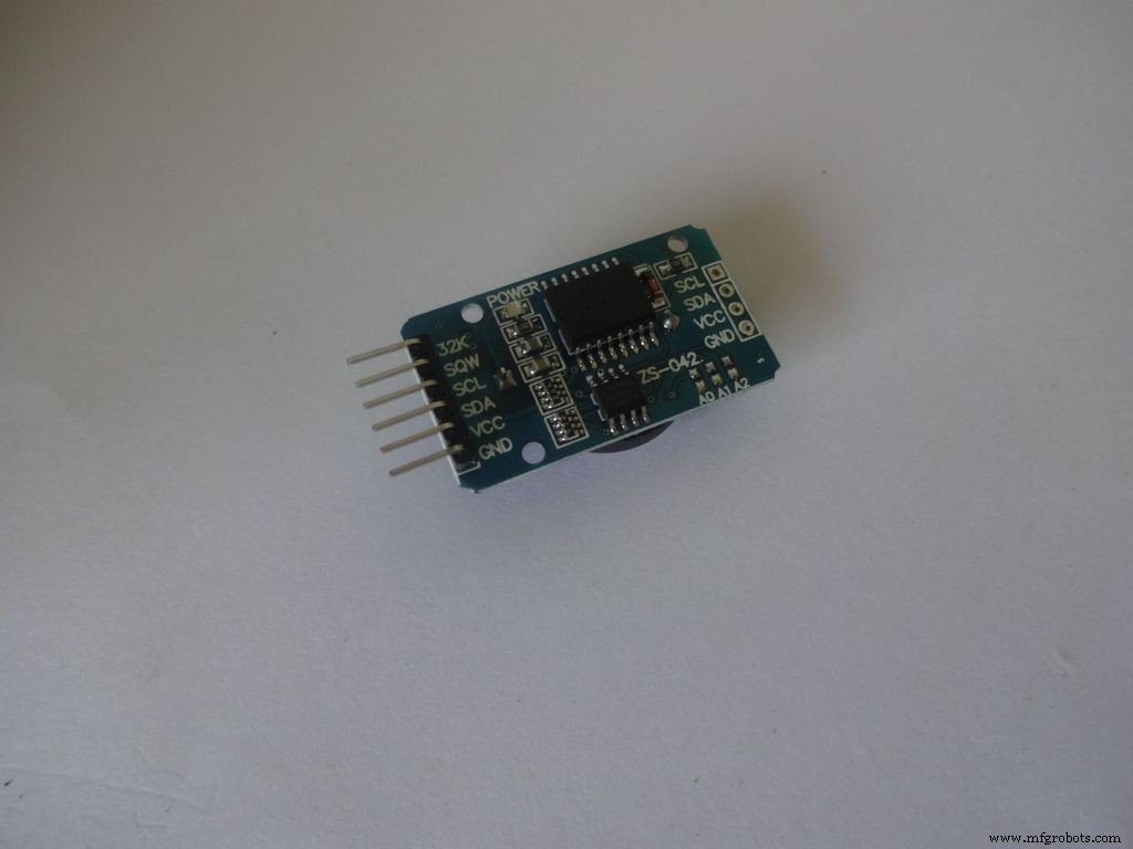
RTC는 초, 분, 시간, 일, 날짜, 월 및 연도 정보를 유지 관리합니다. 내부의 작은 코인 셀 덕분에 외부 전원이 제거되어도 계속 카운팅됩니다. 윤년 수정을 포함하여 31일 미만인 달은 말일을 자동으로 조정합니다.
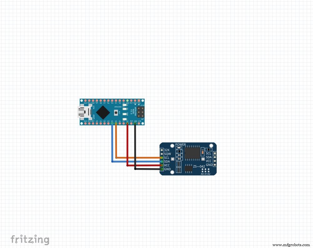
가지고 있는 모듈이 무엇이든 우리는 4개의 핀을 사용할 것입니다:Vcc , GND , SDA 및 SCL . SDA 및 SCL arduino nano 및 uno의 핀은 A4입니다. 및 A5 각기. 다른 arduino의 경우 Google에서 검색하세요!
우리는 시간 설정과 접근을 매우 쉽게 만들어주는 "RTClib" 라이브러리를 사용할 것입니다! 라이브러리는 여기에서 다운로드할 수 있습니다("Download ZIP"을 클릭하고 Arduino 라이브러리 폴더에서 "RTClib-master"를 추출합니다. 라이브러리 설치에 대한 추가 정보)
시간을 설정하려면 이 단계에 첨부된 "RTC_set_time.ino"를 다운로드하고 행의 주석 처리를 제거하십시오.
rtc.adjust(DateTime(F(__DATE__), F(__TIME__)));
컴파일하는 동안 컴퓨터에 설정된 시간을 사용하려는 경우. 또는
<코드>rtc.adjust(날짜시간(2014, 1, 21, 3, 0, 0)); //년, 월, 일, 시, 분, 초
사용자 지정 시간을 설정합니다.
그림과 같이 연결하고 업로드합니다. 일련번호 열기 9600 보드에서 모니터 현재 시간을 보려면. 몇 시간 후에 다시 확인하여 RTC가 어떻게 따라잡고 있는지 확인하십시오.
이 줄을 다시 주석 처리하고 시간을 한 번 설정한 후 다시 업로드하십시오. 그렇지 않으면 Arduino가 재설정될 때마다 계속 재설정됩니다!
코드
// I2C 및 Wire를 통해 연결된 DS1307 RTC를 사용하는 날짜 및 시간 함수 lib#include #include RTC_DS1307 rtc;//RTC_DS1307의 "rtc" 개체 생성, 개체 //객체 및 클래스에 대한 자세한 정보:https://www.youtube.com/watch?v=ABRP_5RYhqUchar daysOfTheWeek[7][12] ={"Sunday", "Monday", "Tuesday", " 수요일", "목요일", "금요일", "토요일"}; 무효 설정 () { Serial.begin(9600); rtc.begin(); // 다음 줄은 RTC를 이 스케치가 컴파일된 날짜 및 시간으로 설정합니다. // rtc.adjust(DateTime(F(__DATE__), F(__TIME__))); // 이 줄은 명시적인 날짜 및 시간으로 RTC를 설정합니다. 예를 들어 // 2014년 1월 21일 오전 3시에 설정하려면 다음을 호출합니다. // rtc.adjust(DateTime(2014, 1, 21, 3, 0, 0) );} 무효 루프 () { 현재 날짜 시간 =rtc.now(); Serial.print(now.year()); Serial.print('/'); Serial.print(now.month()); Serial.print('/'); Serial.print(now.day()); Serial.print("("); Serial.print(dayOfTheWeek[now.dayOfTheWeek()]); Serial.print(") "); Serial.print(now.hour()); Serial.print(':'); Serial.print(지금.분()); Serial.print(':'); Serial.print(now.second()); 직렬.println(); 직렬.println(); 지연(1000);}
6단계:최종 설정
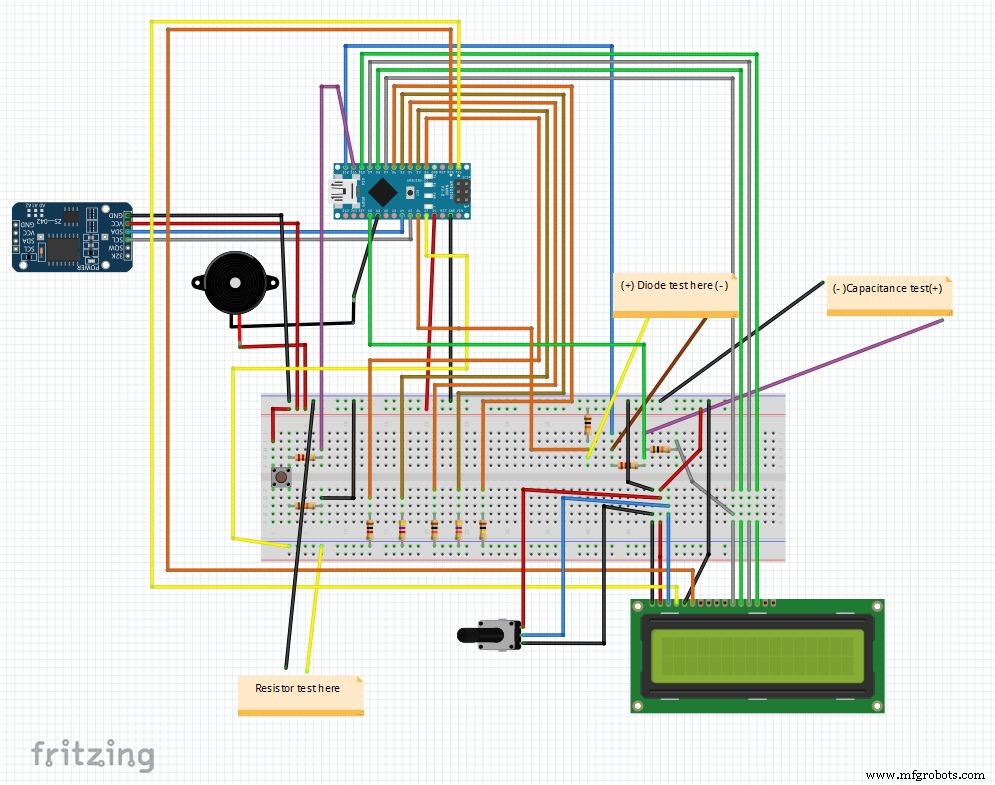
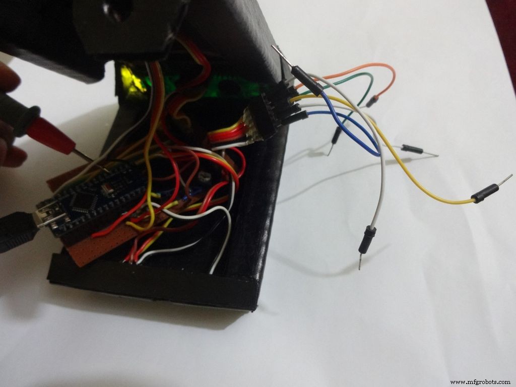
모든 요소를 결합한 후의 최종 회로입니다. 메인 코드와 프리징 파일은 마지막에 첨부합니다.
fritzing.org에서 아직 다운로드하지 않았다면 fritzing을 다운로드하십시오.
Main_code.rar 파일을 추출하고 Main_file_rtc.ino를 엽니다. 별도의 definations.h에 모든 변수 선언을 포함했습니다. 헤더 파일은 기본 코드를 열 때 자동으로 추가됩니다.
다른 부분은 함수로 만들어집니다: Clock() , findResistance() , findCapcitance() 및 다이오드 테스트() . 이들은 별도의 탭에 작성되어 읽기 쉽고 변경 사항을 구현하기 쉽습니다. 기본 파일은 "모드 버튼"의 상태를 확인하고 적절한 기능을 호출합니다.
기타 세부 사항은 코드 자체에 적절하게 설명되어 있습니다.
브레드보드에서 테스트를 실행한 후 IC 만들기를 시작할 준비가 되었습니다!
참고:부저는 아직 사용하지 않는 경우 연속성 기능과 같이 필요할 때 사용할 수 있습니다.
7단계:스위치 준비
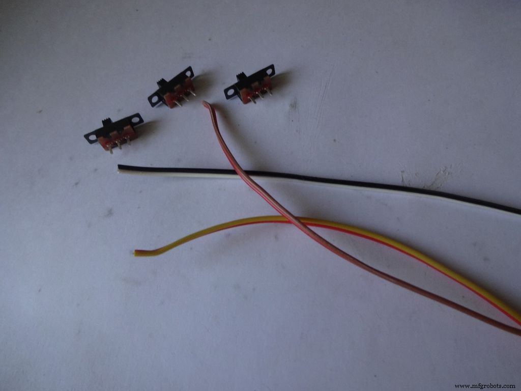
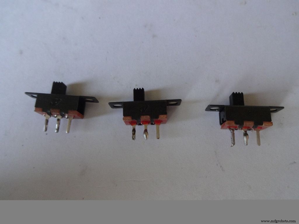


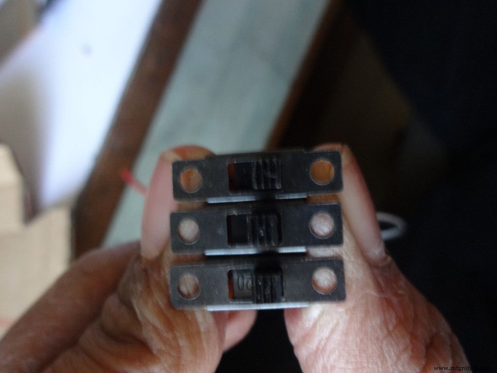
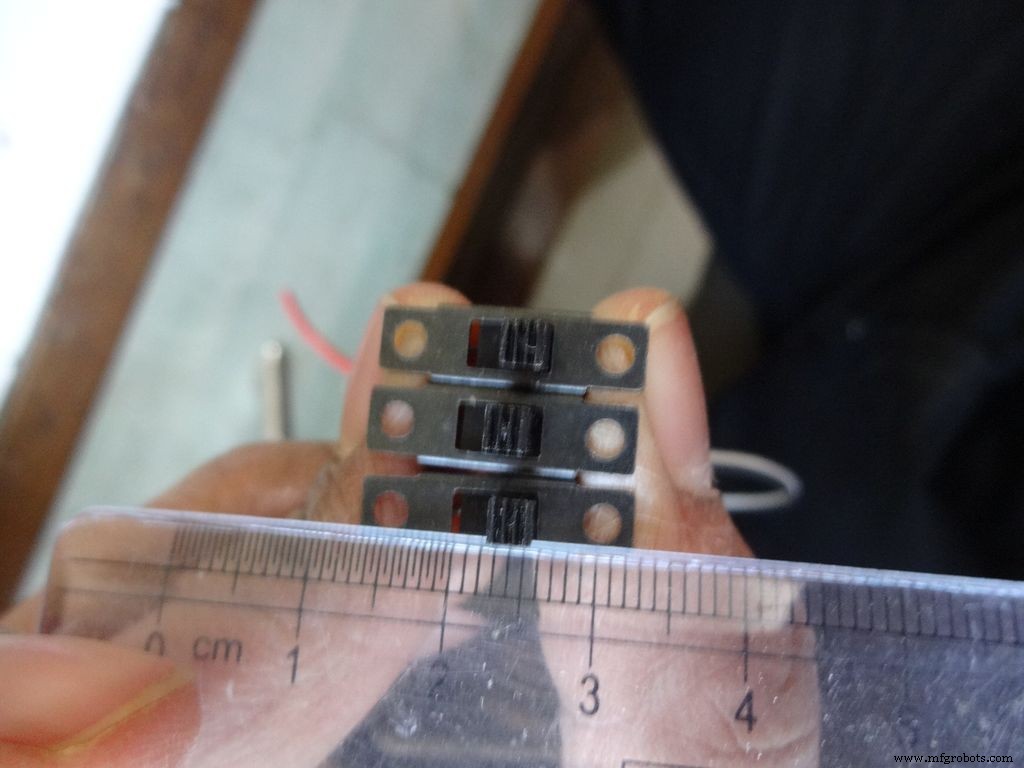
약 10cm 길이의 3 쌍의 와이어와 함께 3 개의 슬라이드 스위치를 가져옵니다. 이를 위해 리본 케이블을 나눕니다.
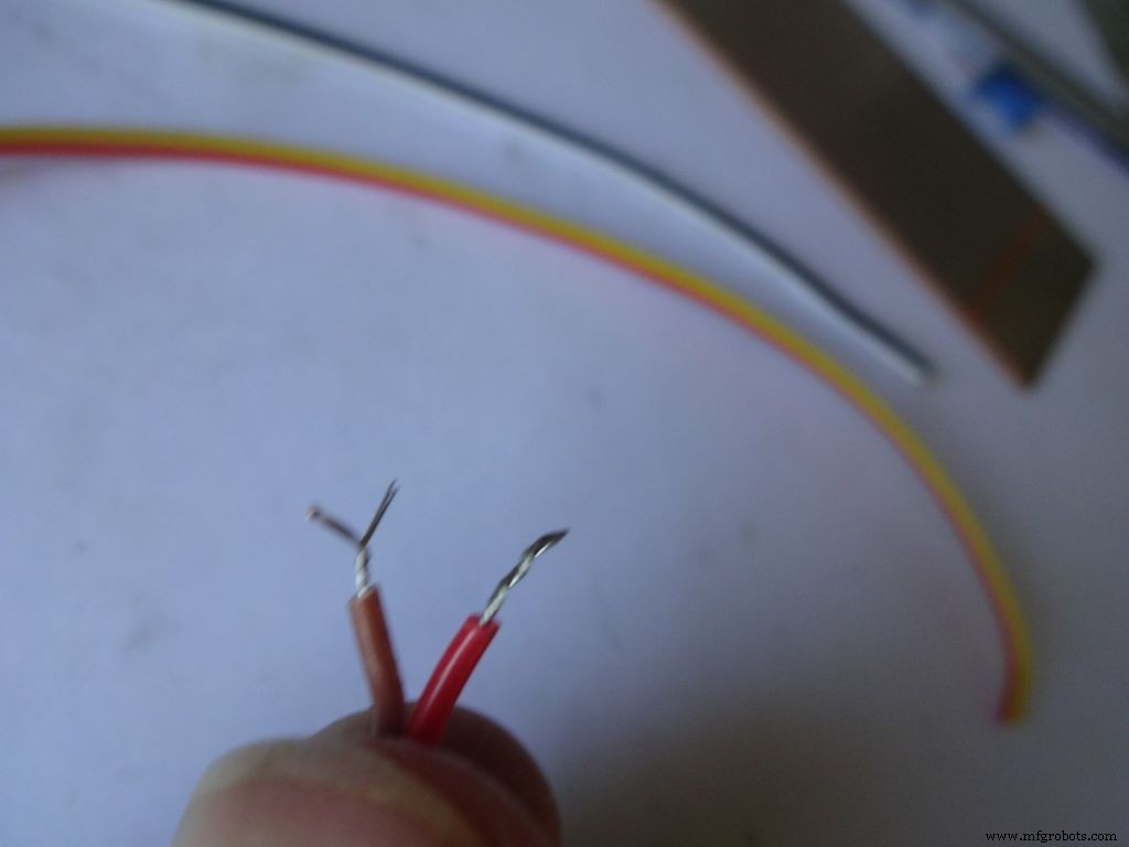
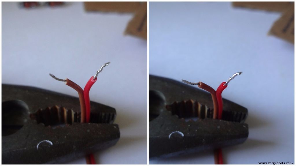
절연체의 작은 부분(5mm 이하)을 벗겨내고 가닥을 꼬아줍니다.
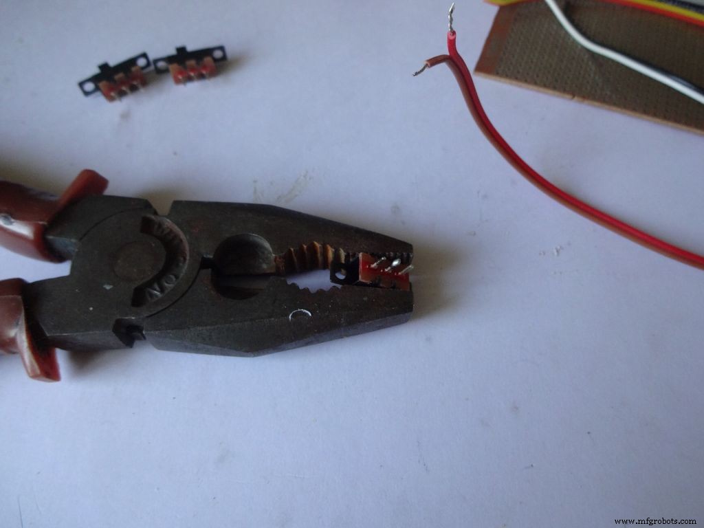
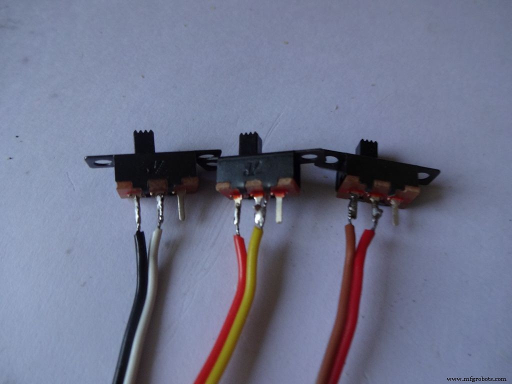
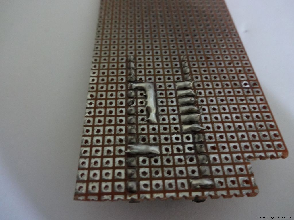
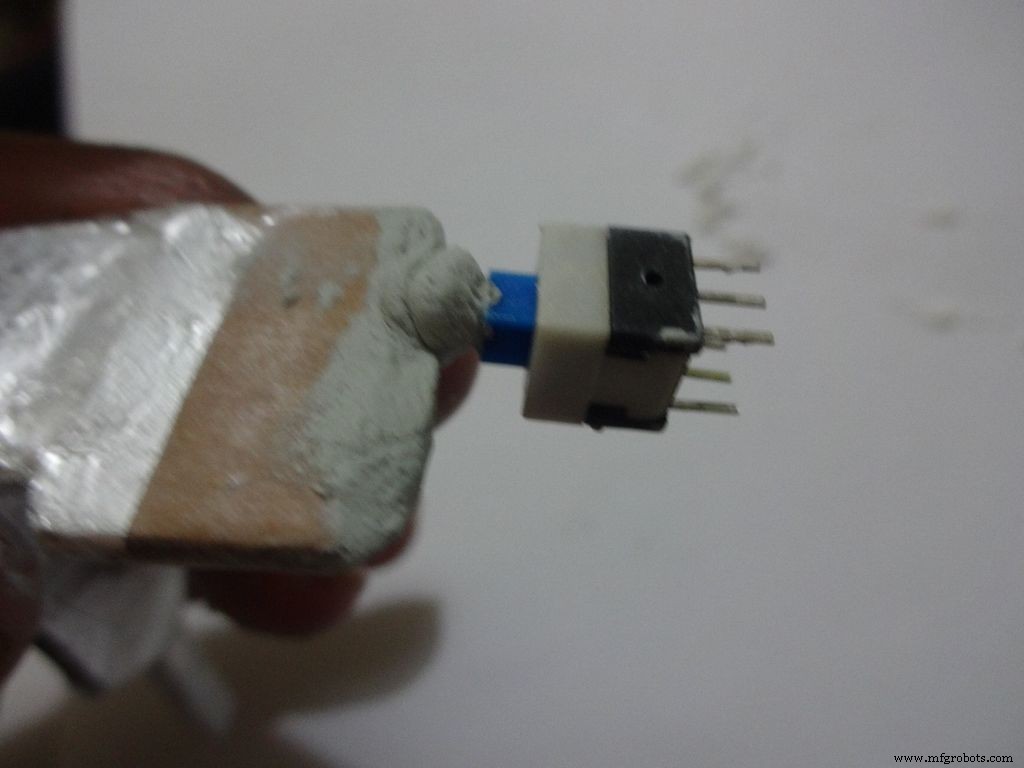
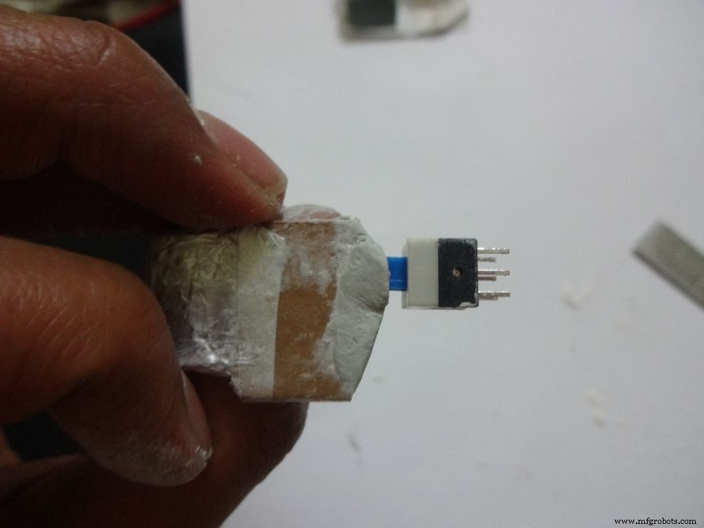
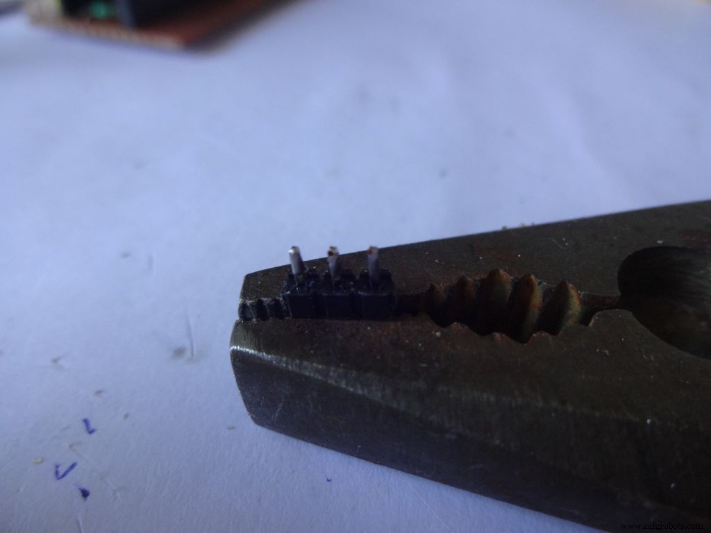
각 스위치의 인접한 2개의 핀에 약간의 땜납을 바르십시오. 그것을 고정하기 위해 무언가를 사용하십시오. 납땜하는 동안 제자리에 무거운 펜치를 사용했습니다.
이전에 납땜한 적이 없다면 지금이 시작하기에 좋은 시기입니다. Youtube에는 올바르게 납땜하는 방법을 설명하는 수많은 비디오가 있습니다. PACE의 수업은 매우 유익하므로 시청하십시오.
다음으로 우리는 전선을 '주석'해야 합니다. 주석 도금할 와이어에 납땜 인두의 끝 부분을 터치합니다. 팁과 와이어 사이에 약간의 땜납을 바르면 팁에서 와이어로 열을 전도하는 브리지가 생성됩니다. 그런 다음 납땜 인두 팁의 반대쪽에 있는 와이어에 직접 납땜을 적용합니다. . 땜납을 제거합니다. 팁을 제거합니다. 이에 대한 동영상입니다.
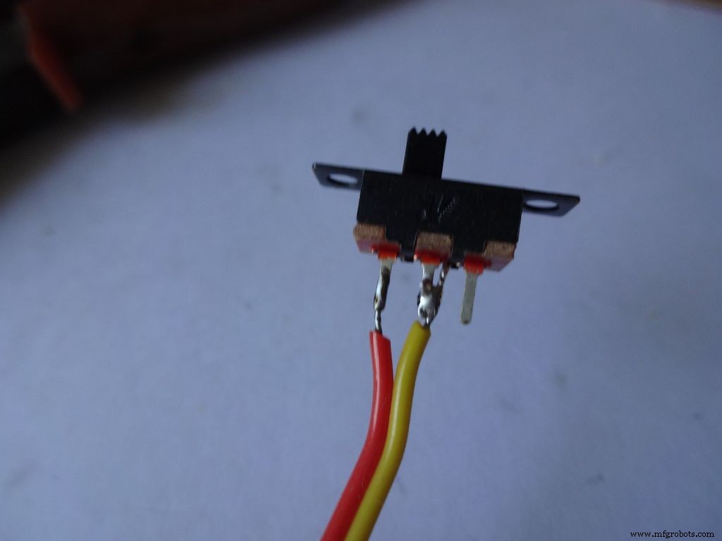
그런 다음 스위치를 제자리에 잡고 주석 도금된 와이어 중 하나를 핀으로 가져오고 납땜 인두를 만져서 납땜을 리플로합니다. 두 번째 와이어와 동일하게 수행하십시오. 스위치의 한쪽에 어두운 색의 전선을 배치한 것을 주목하십시오.
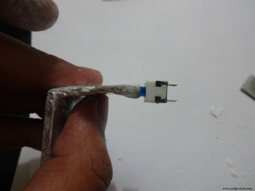
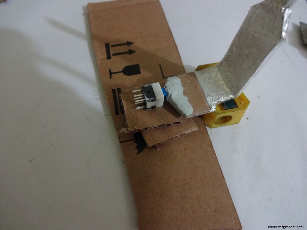
이제 절차를 반복하고 푸시 버튼에 두 개의 와이어를 연결하십시오(이것은 리셋 버튼이 됩니다). 일반적으로 연결된 버튼 끝에 전선을 연결하지 마세요.
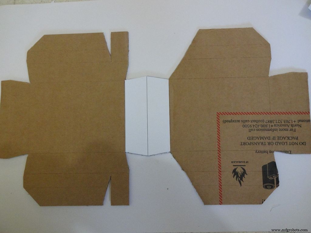
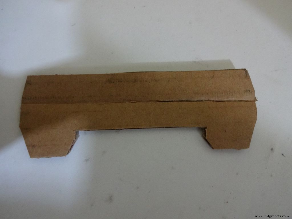
8단계:사례 만들기 - 레이아웃 자르기
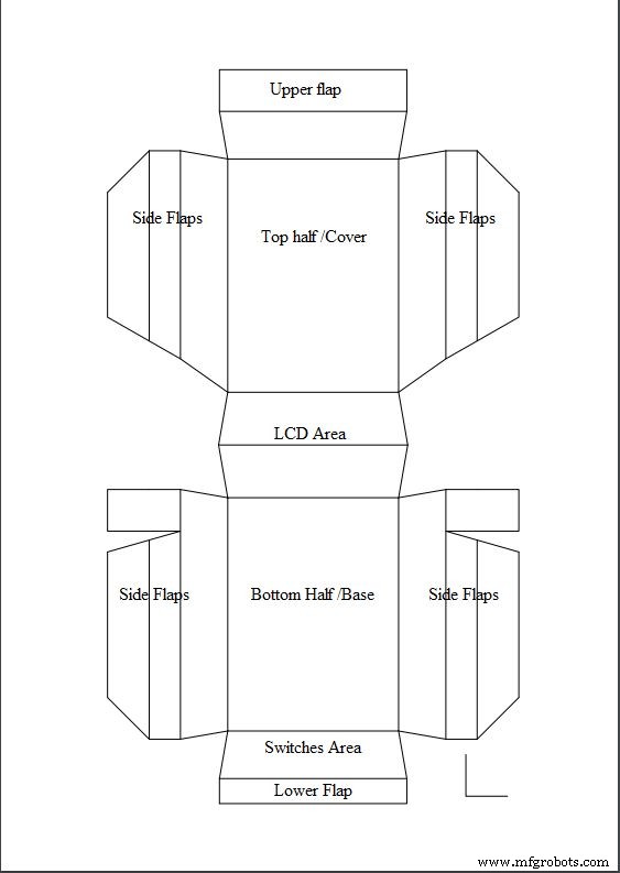
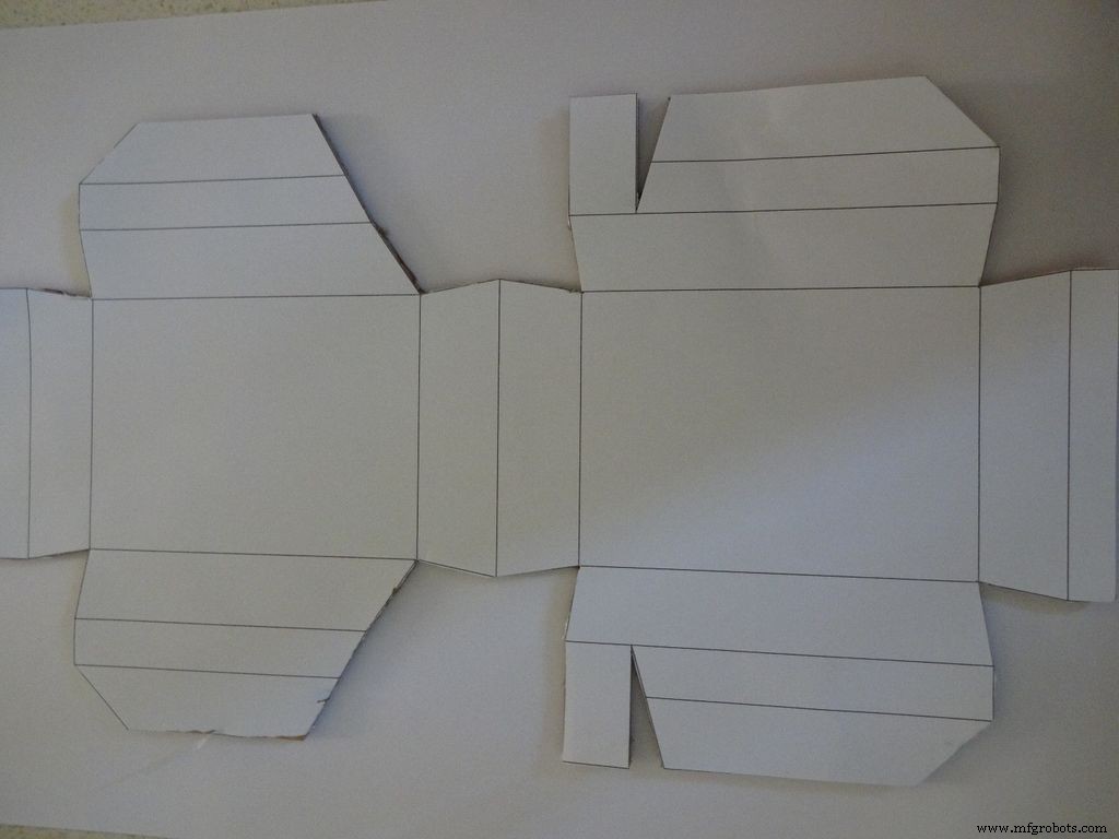
해당 지역에서 사용 가능한 용지 크기를 기준으로 "Layout_Final_A3.pdf" 또는 ""Layout_Final_ANSI_B.pdf"를 다운로드하십시오. 마지막에 첨부되어 있습니다.
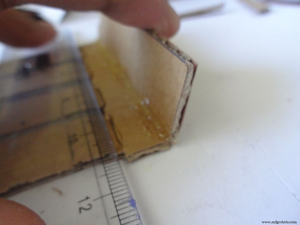
A3 크기 용지(29.7 x 42.0cm 또는 11.69 x 16.53인치) 또는 미국 대체 ANSI B(11 x 17인치 또는 279 x 432mm)에 인쇄합니다. 인쇄하는 동안 적절한 용지 크기, 방향을 선택하고 "실제 크기" 옵션을 선택했는지 확인하십시오. 오른쪽 하단 모서리의 작은 직각을 측정하여 인쇄가 정확한지 확인합니다. 2cm x 2cm이어야 합니다.
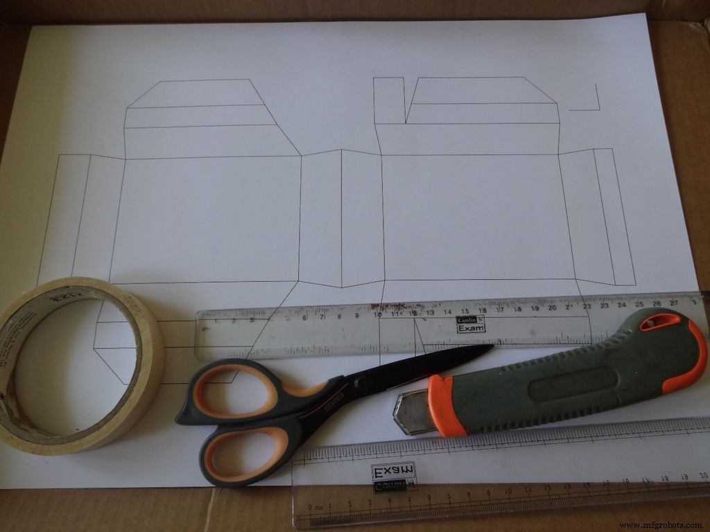
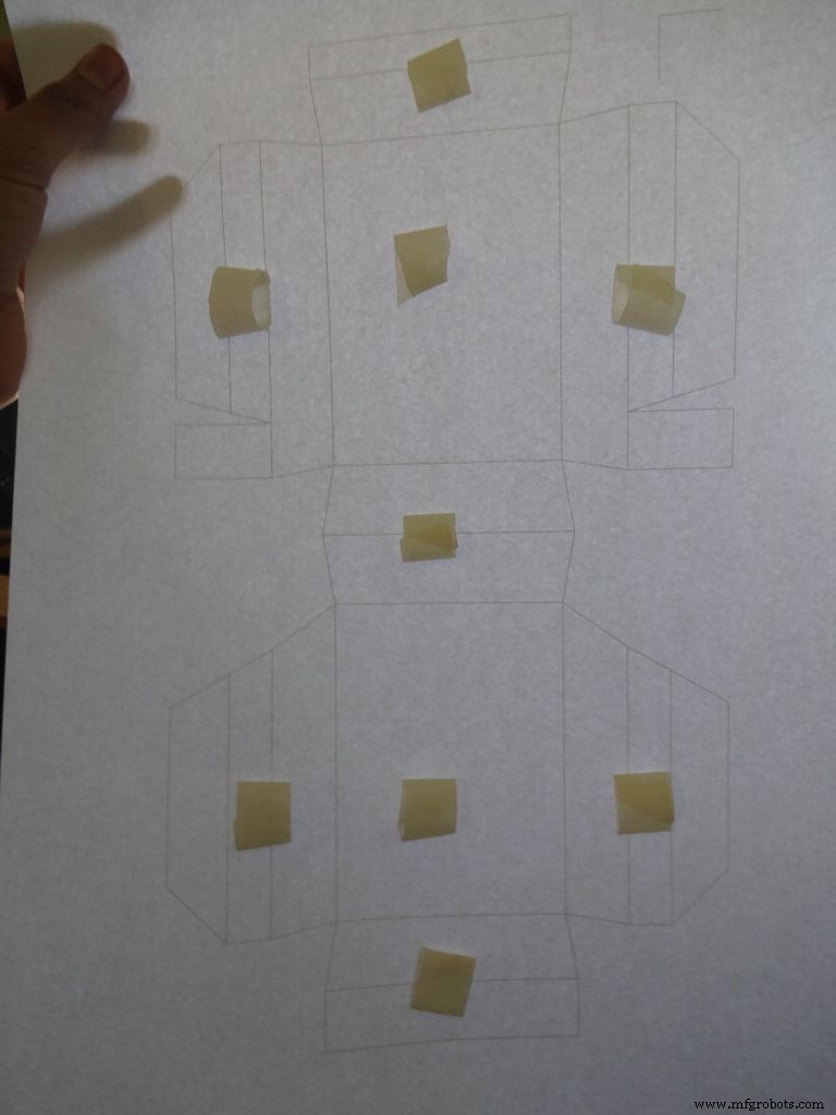
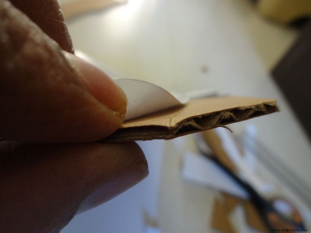
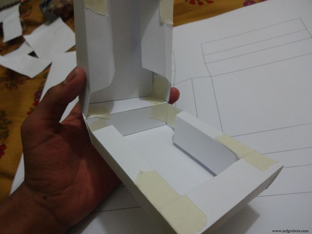
레이아웃보다 대략적으로 판지 조각을 자릅니다. 작은 테이프 조각을 찢고 '양면 점착' 롤을 만들어 표시된 위치에 부착합니다. 그런 다음 판지에 시트를 붙입니다.
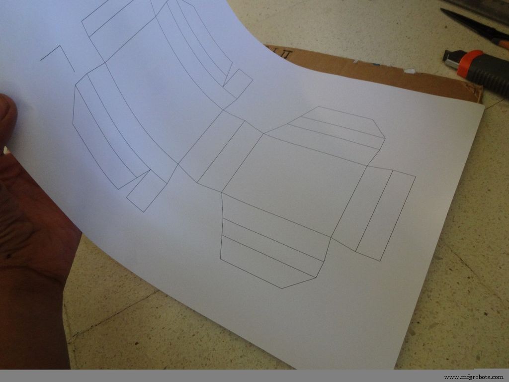
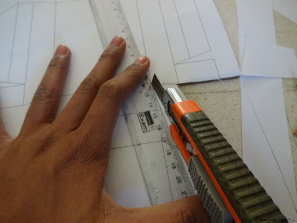
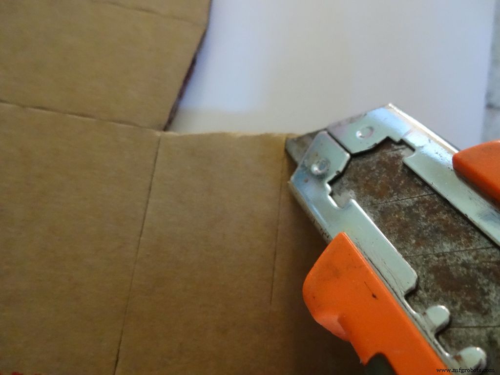
케이스 레이아웃의 바깥쪽 경계를 자르려면 날카로운 가위나 상자 절단기를 자를 사용하여 자릅니다. 가위보다 박스 커터가 훨씬 낫다는 것을 알았습니다. 대부분의 절단기에는 신선하고 날카로운 팁을 얻기 위해 단계적으로 부러질 수 있는 날이 있으므로 그렇게 하는 것이 좋습니다. 자르는 부분 아래에 판지나 나무 조각을 하나 더 두십시오. 이렇게 하면 더 깔끔하게 자르는 데 도움이 됩니다.
또한 자르는 동안 자를 선에 제대로 유지하지 않는 것도 일반적인 오류입니다. 서두르지 마십시오.
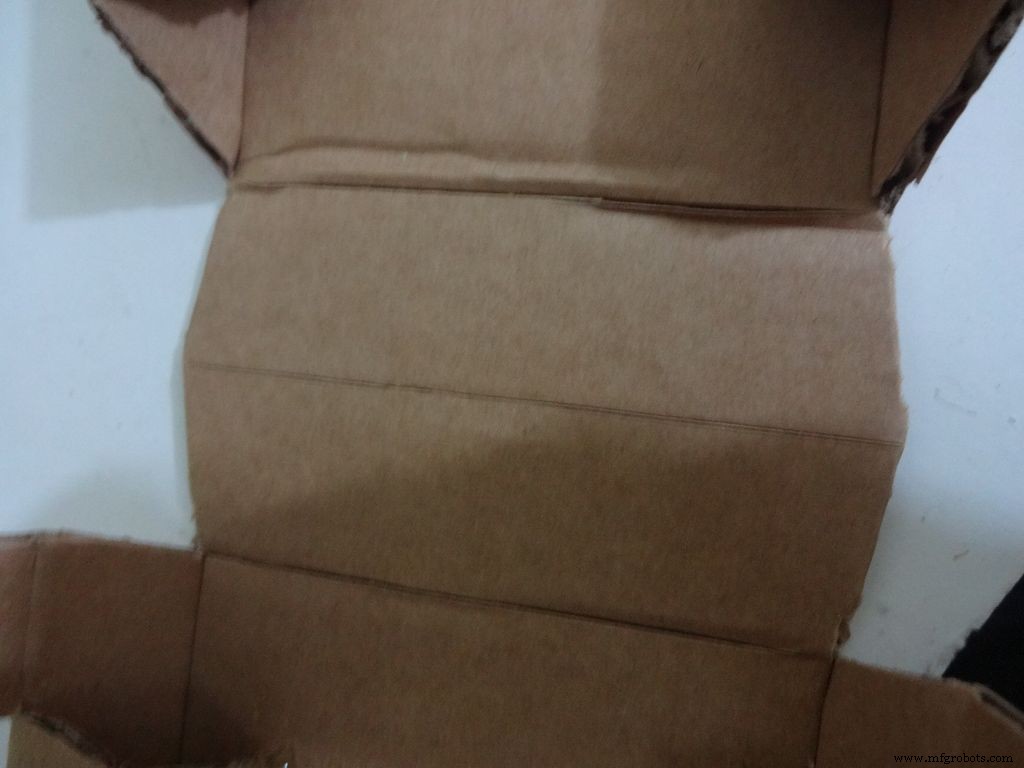
9단계:케이스 만들기 - 주름 및 접기
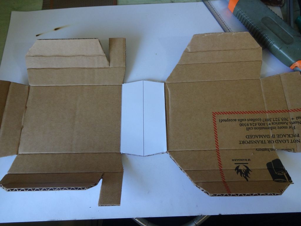
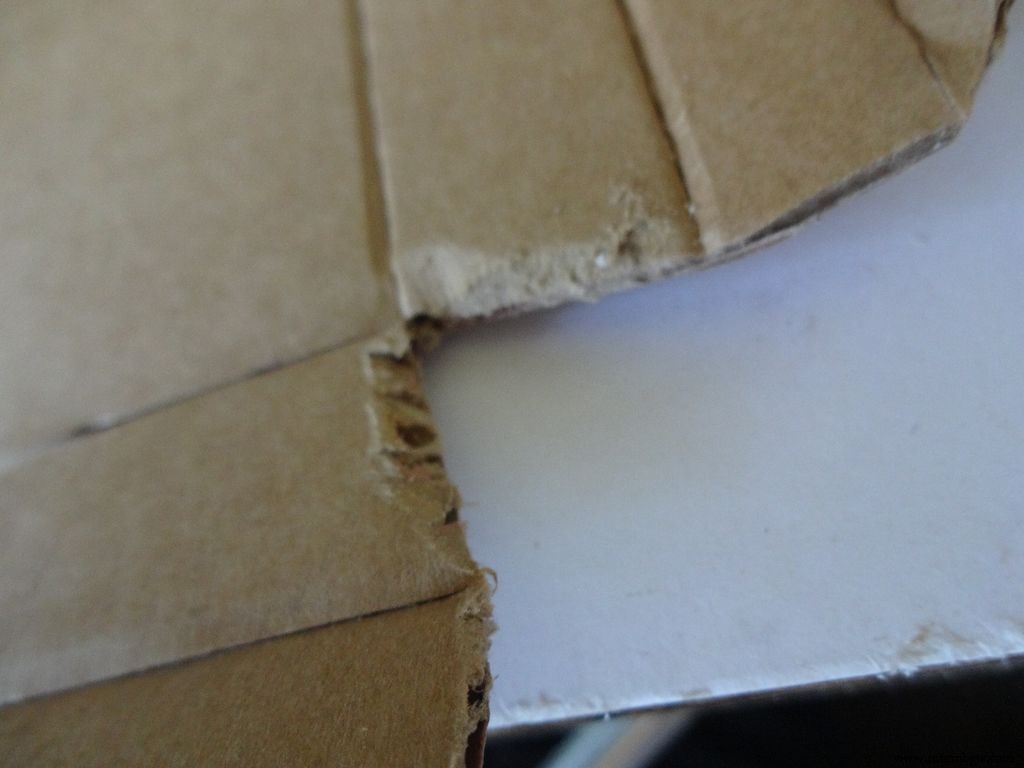


눈금이 있는 커터를 사용하여 LCD 영역의 중간 선을 제외한 모든 접는 선을 따라 조심스럽게 주름을 만듭니다. . 접을 수 있는 모든 부분을 구부리고 접고 불완전한 주름을 수정하십시오.
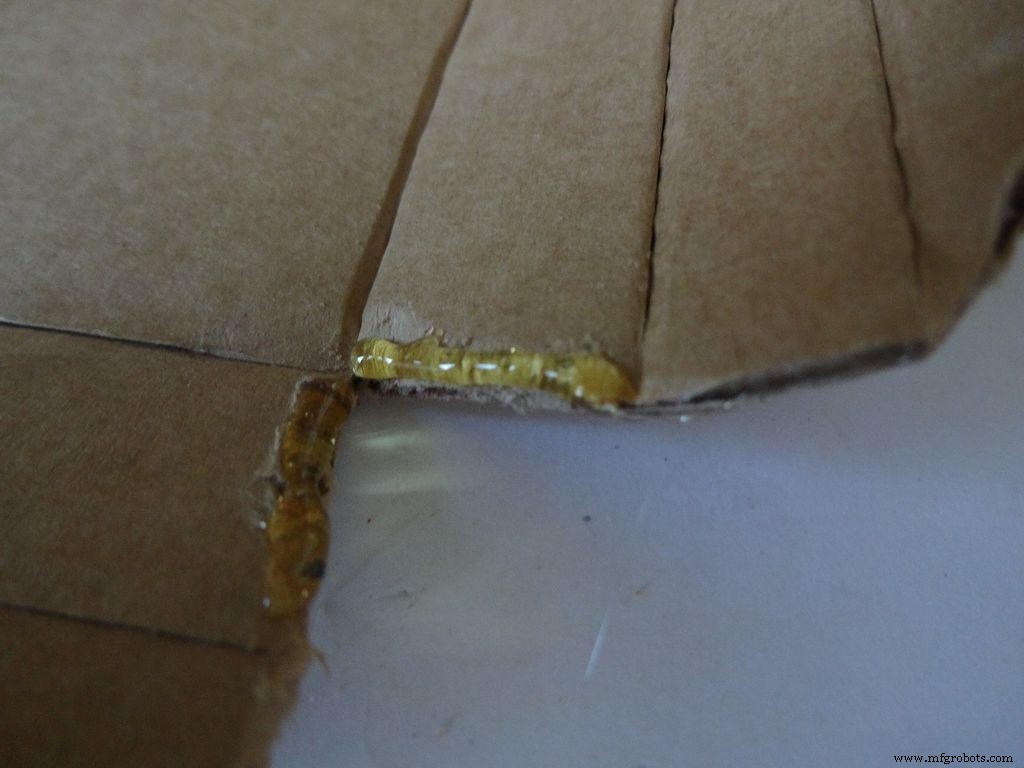
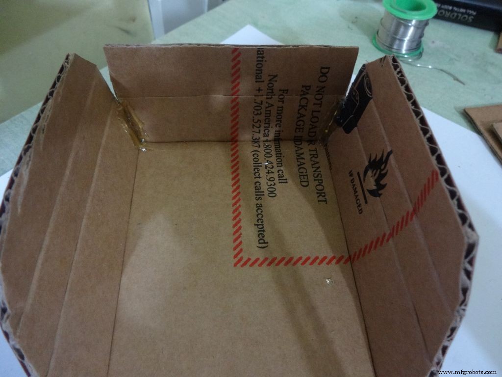
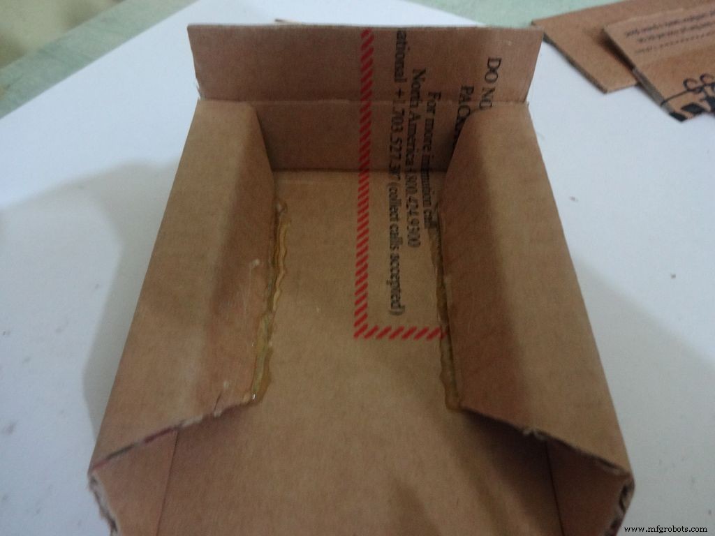
하반부 또는 베이스용:
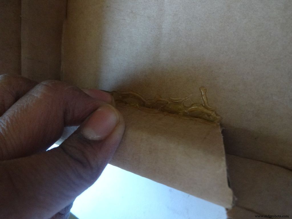
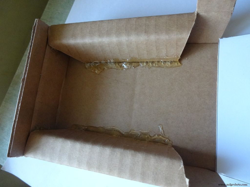
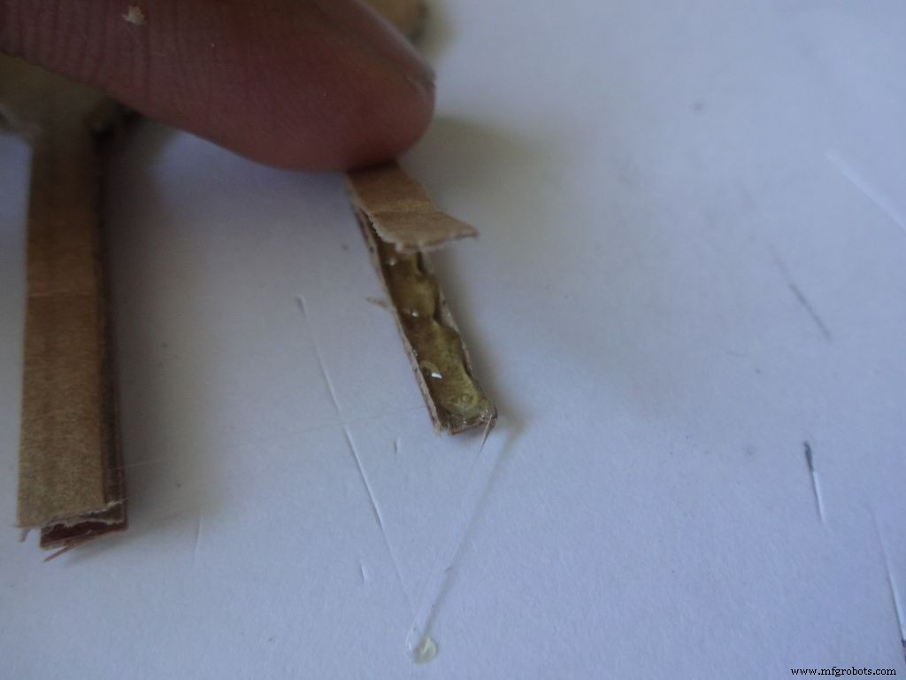
사포를 사용하여 경사면에서 처음 네 모서리를 사포하고, 글루건으로 뜨거운 접착제를 바르고(한 번에 한 면씩), 접착제가 식을 때 결합하고 30-60초 동안 유지합니다.
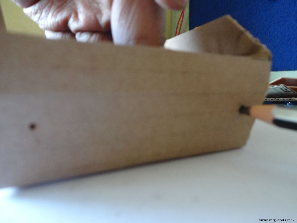
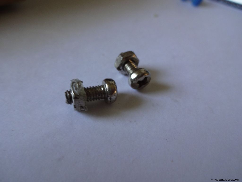
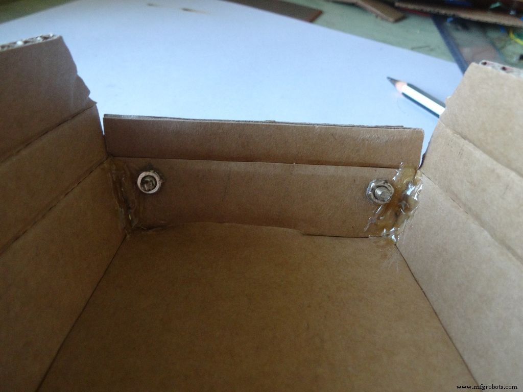
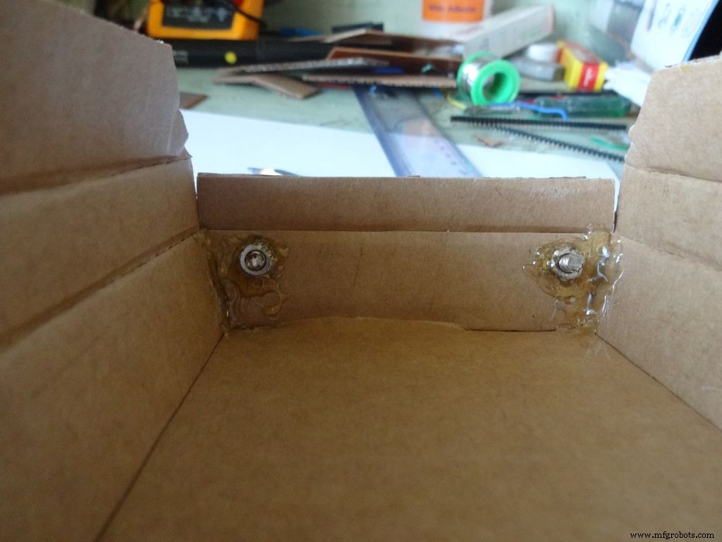
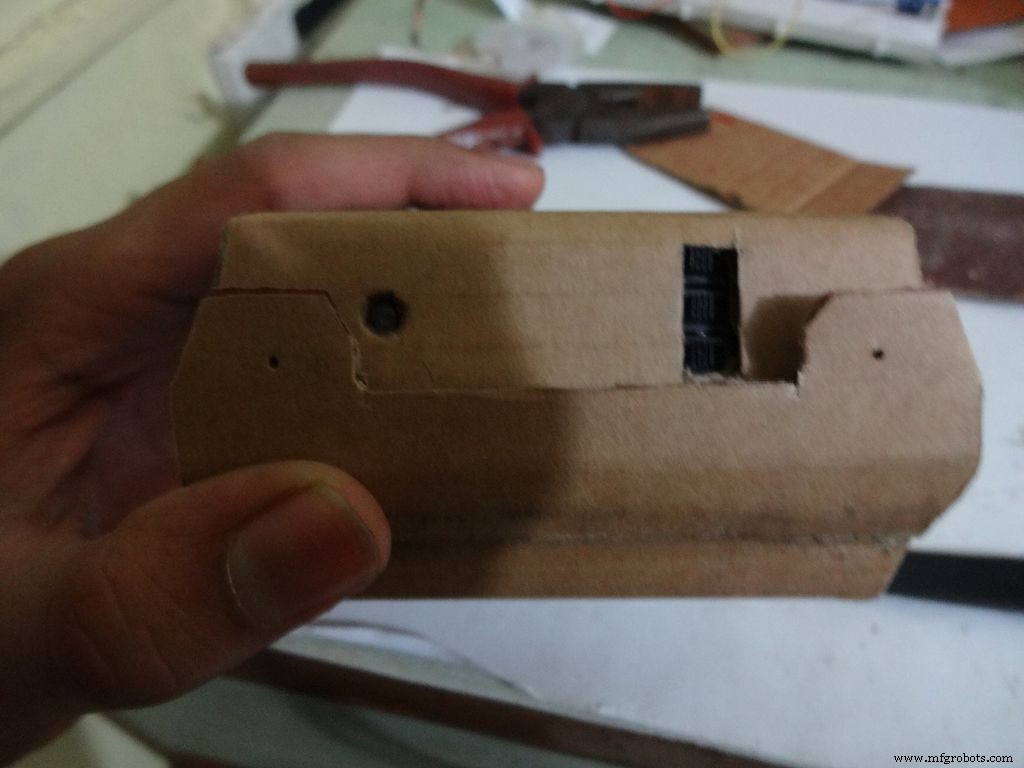
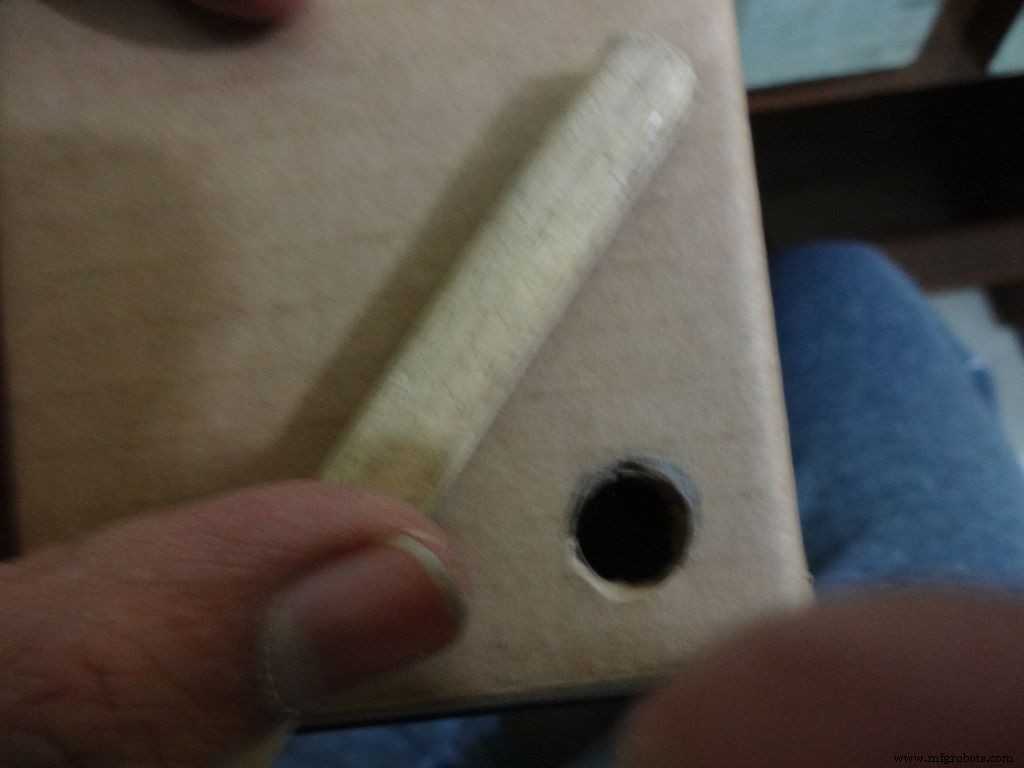
그림과 같이 집게로 두 개의 구멍을 만들고 볼트가 들어갈 만큼만 연필로 확대합니다. 내부의 너트를 조이고 뜨거운 접착제(너트에만!)를 바르고 식힙니다. 드라이버로 볼트를 제거합니다.
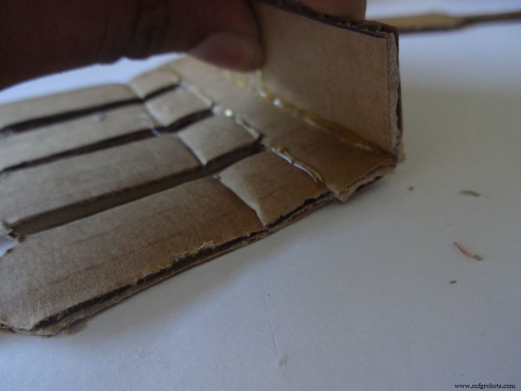
그런 다음 두 개의 측면 덮개를 안쪽으로 접고 붙입니다. 플랩의 바깥 부분은 약간 기울어지고 중간 부분은 평평해야 합니다.
10단계:사례 만들기 - 스위치 추가
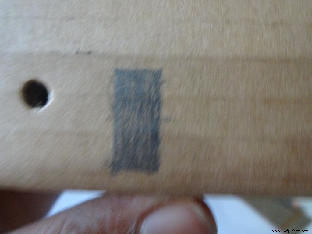
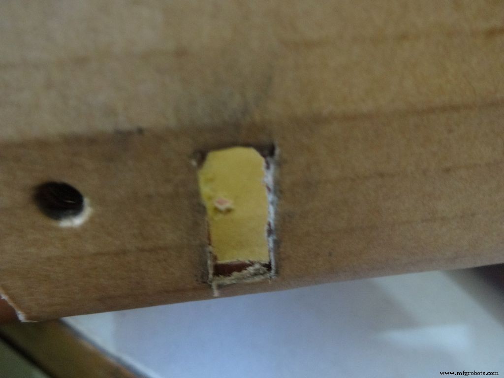
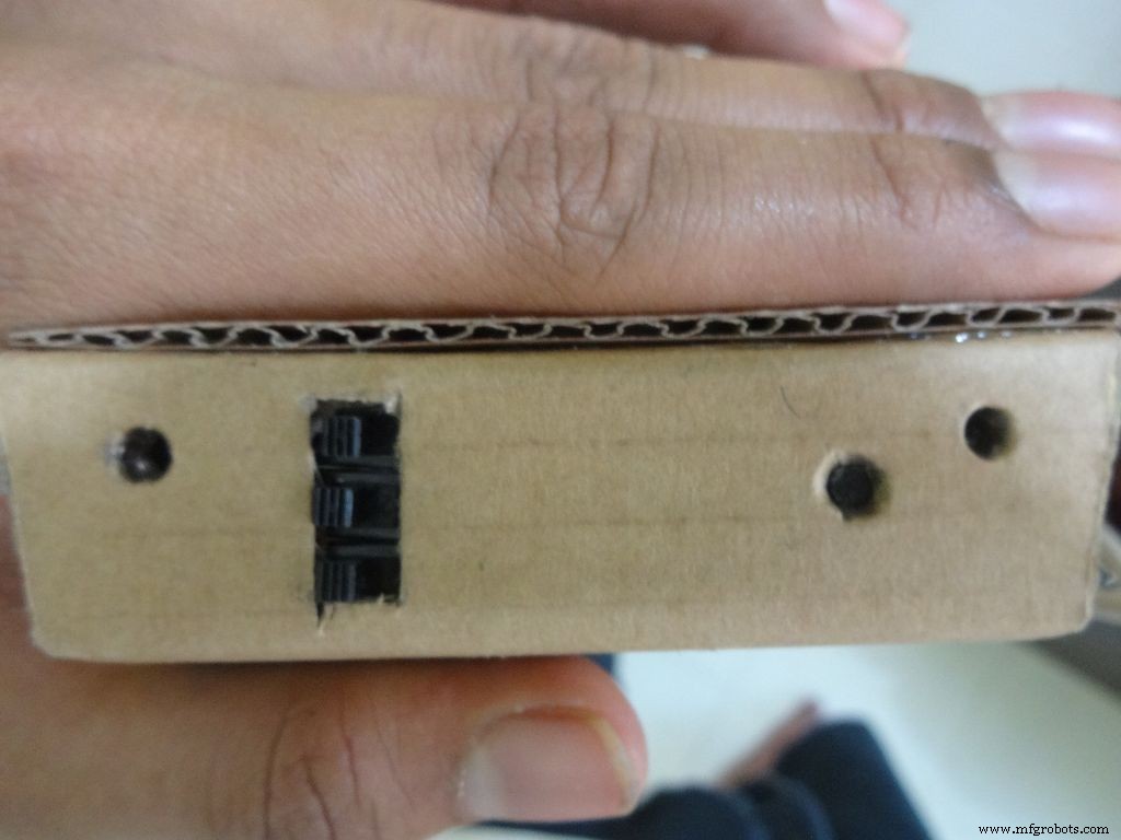

Take the 3 sliding switches with wires we soldered earlier, measure the approximate dimension of rectangle needed. Mark it on the left side of the box(left from the outside). Cut it with a cutter, sand it a bit on the inside to remove any material sticking out.
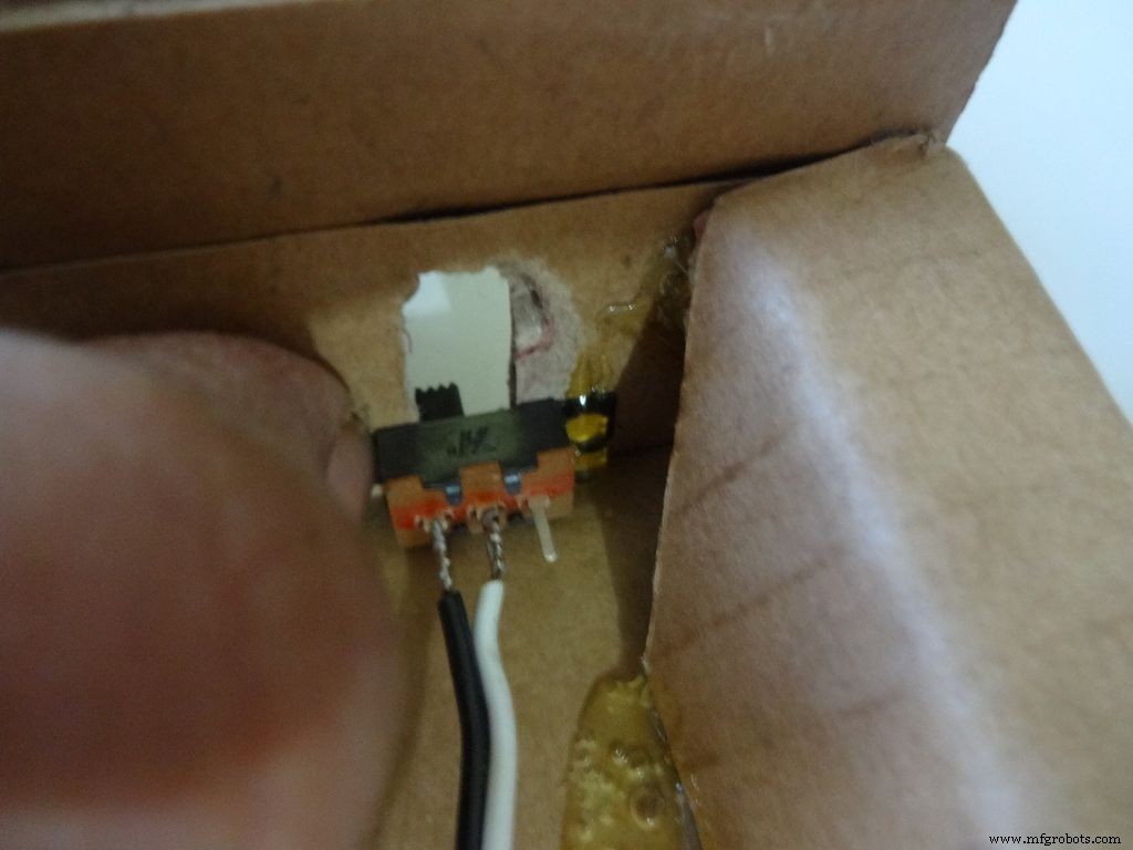
Keep the first switch in position and while holding it add glue on one side. Let it cool. Repeat with the other two as well, and then add glue on the remaining sides. Note:The wired pins of the switches should be on the same side.
Make another hole on the other side for the reset pushbutton. Hold the button in place and add glue. Fold the lower flap inwards and stick it.
Step 11:Making the case - Top half or cover
Sand the edges and stick the side flaps inwards(just like the base) for the top half
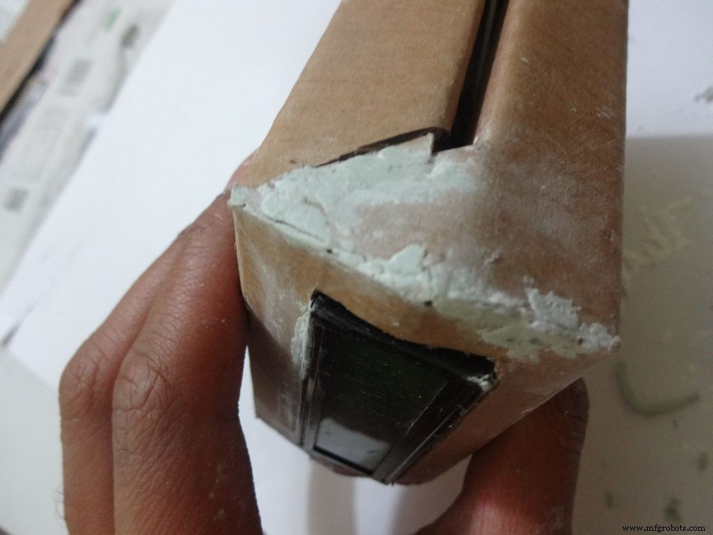
Step 12:Making the case - Adding the LCD
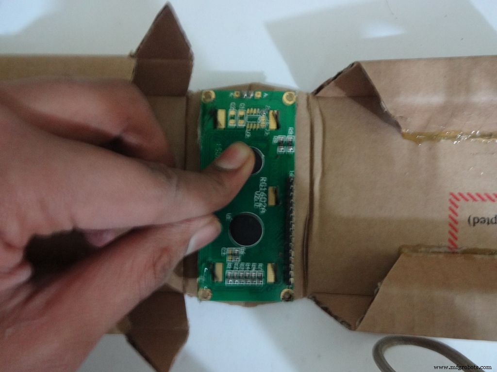
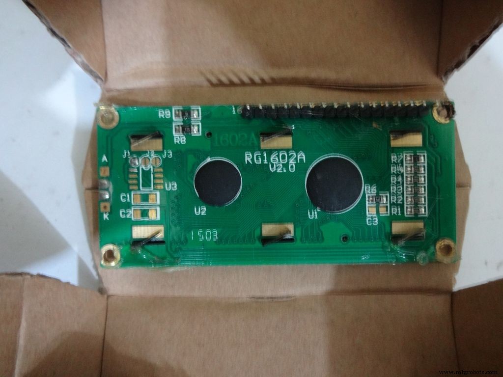
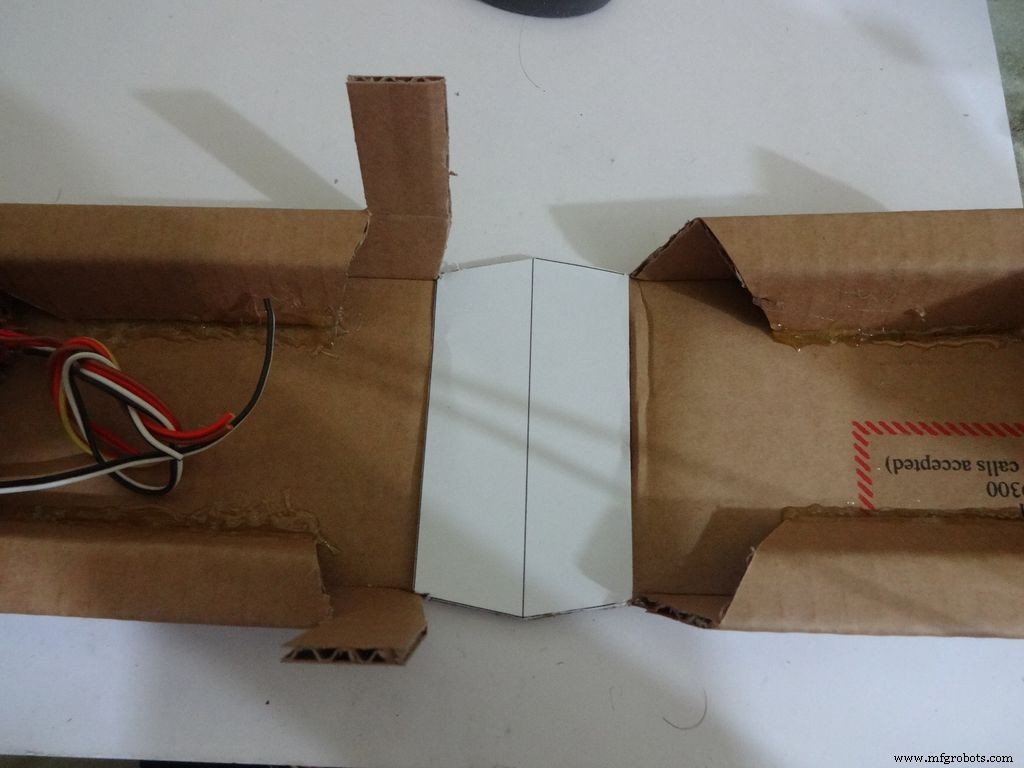
Crease the middle line. (Didn't do it earlier as it is delicate and gets loose soon).
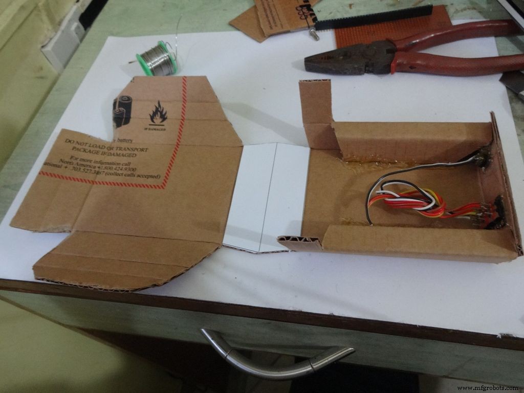
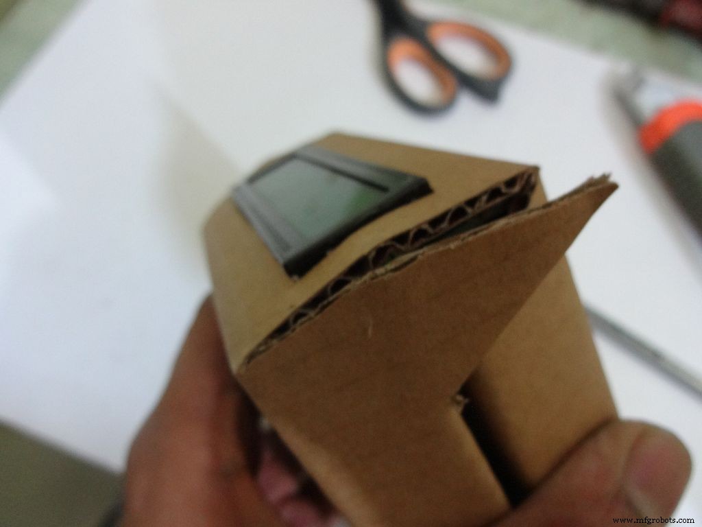
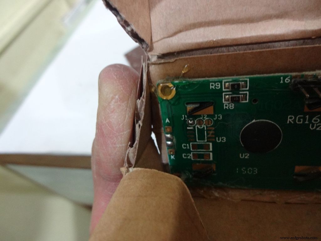
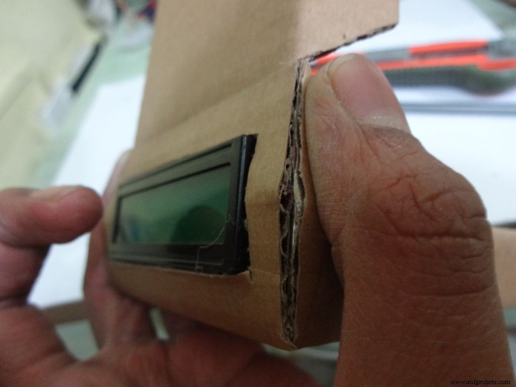
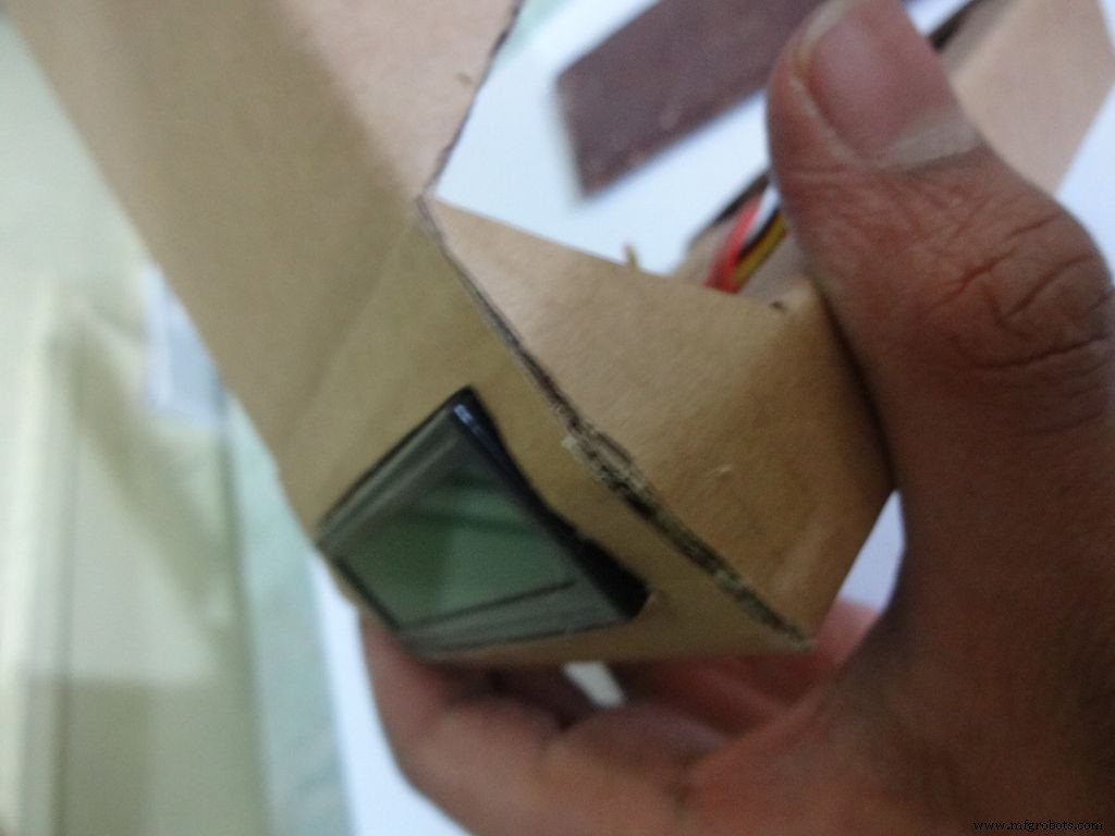
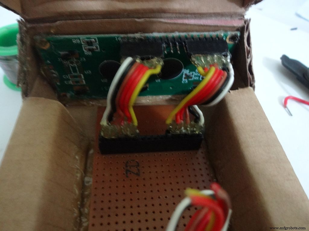
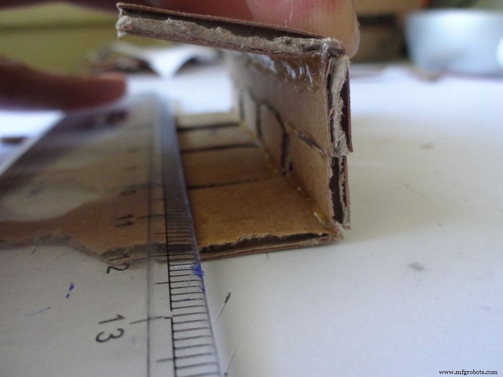
Fold the cover over to the base and check whether everything looks alright, sufficient spacing should be left for the IC pins. (See photo)
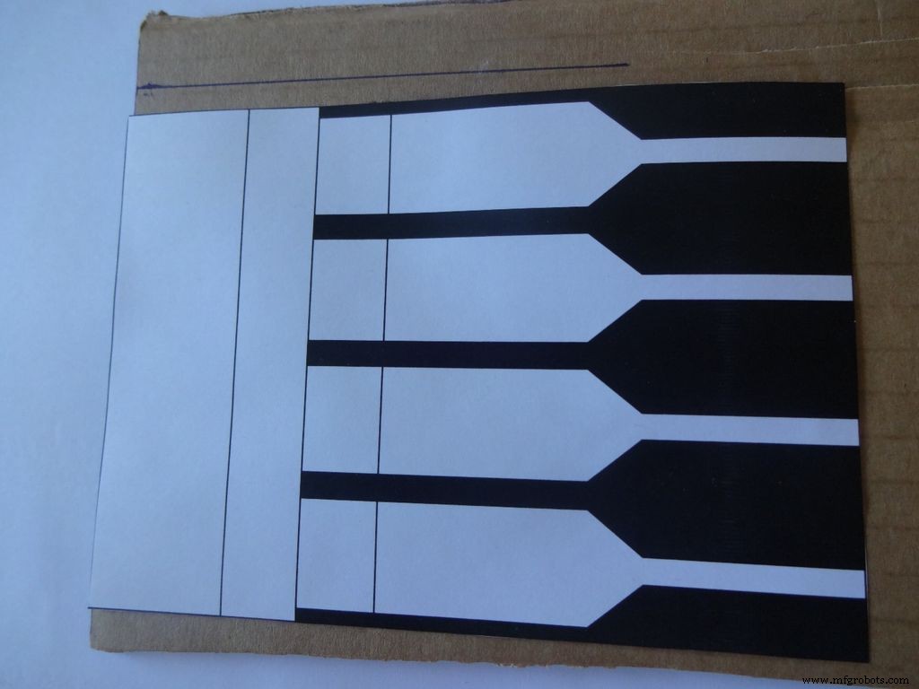
Cut the covering flaps as shown in the images.
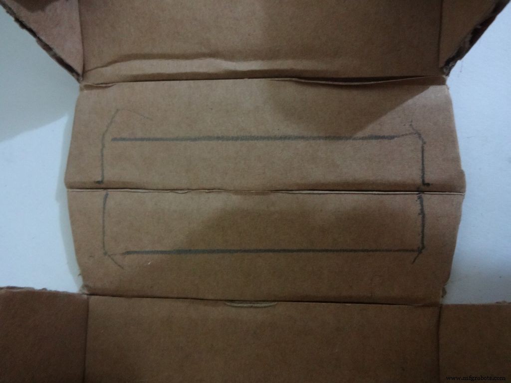
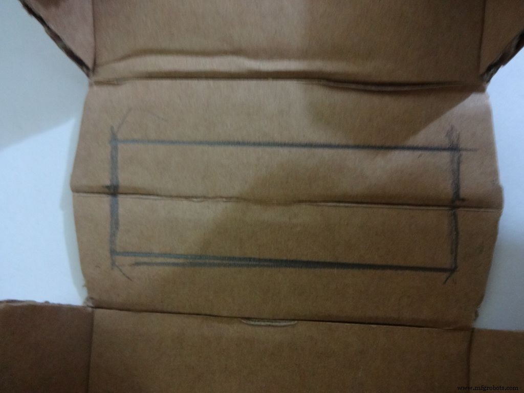
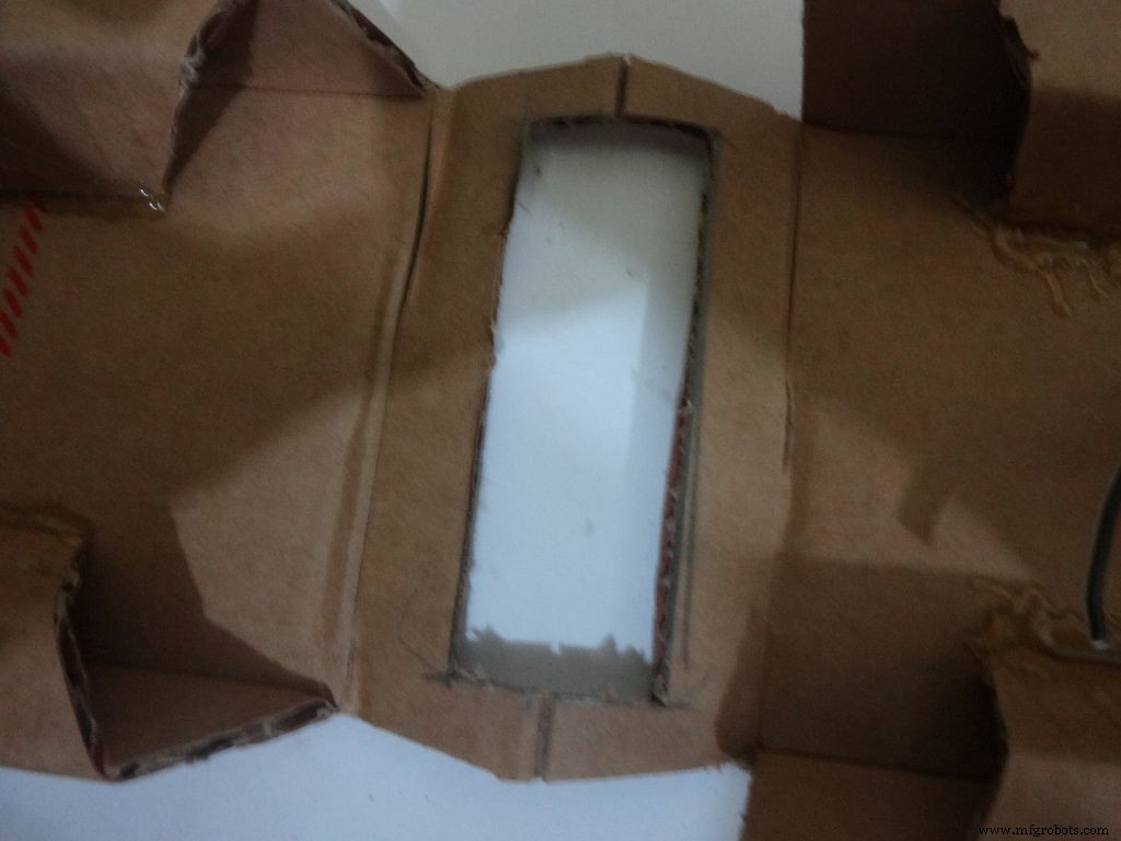
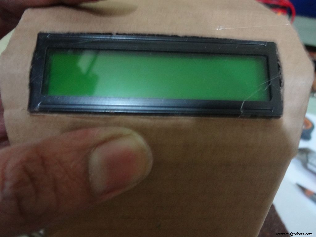
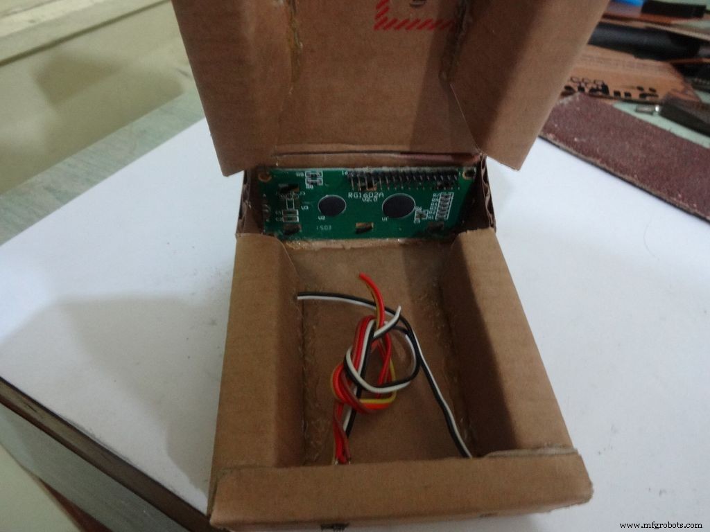
Keep the LCD at the center of the LCD Area, mark it with a pencil. Using a ruler, make the rectangle properly and cut it carefully using a cutter. Fold the LCD window and apply glue to the hinges to keep them at their correct position. Insert the LCD and make any modifications if required.
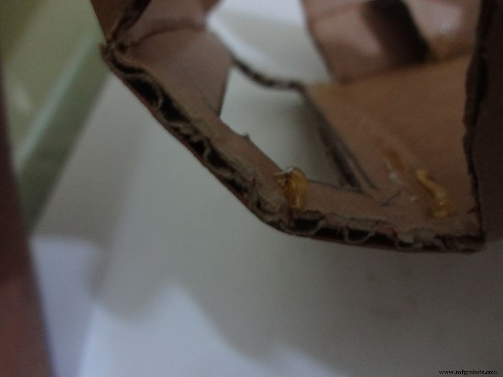
Finally, apply glue to the four corners(don't put excess) of the LCD and place it in position.
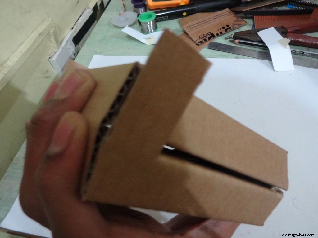
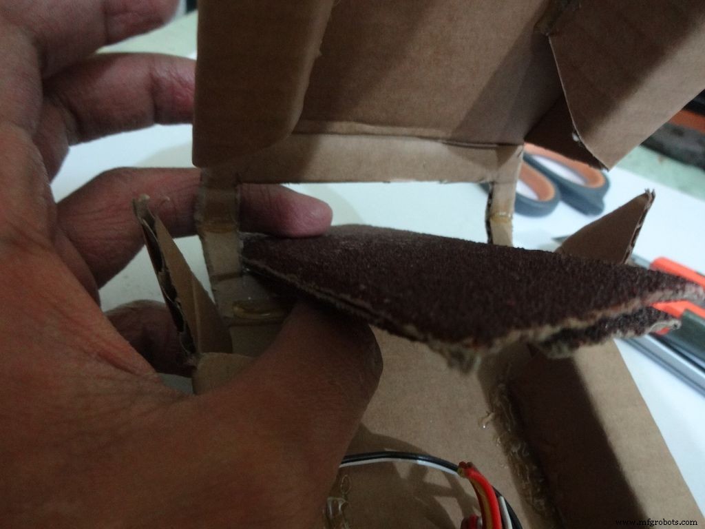
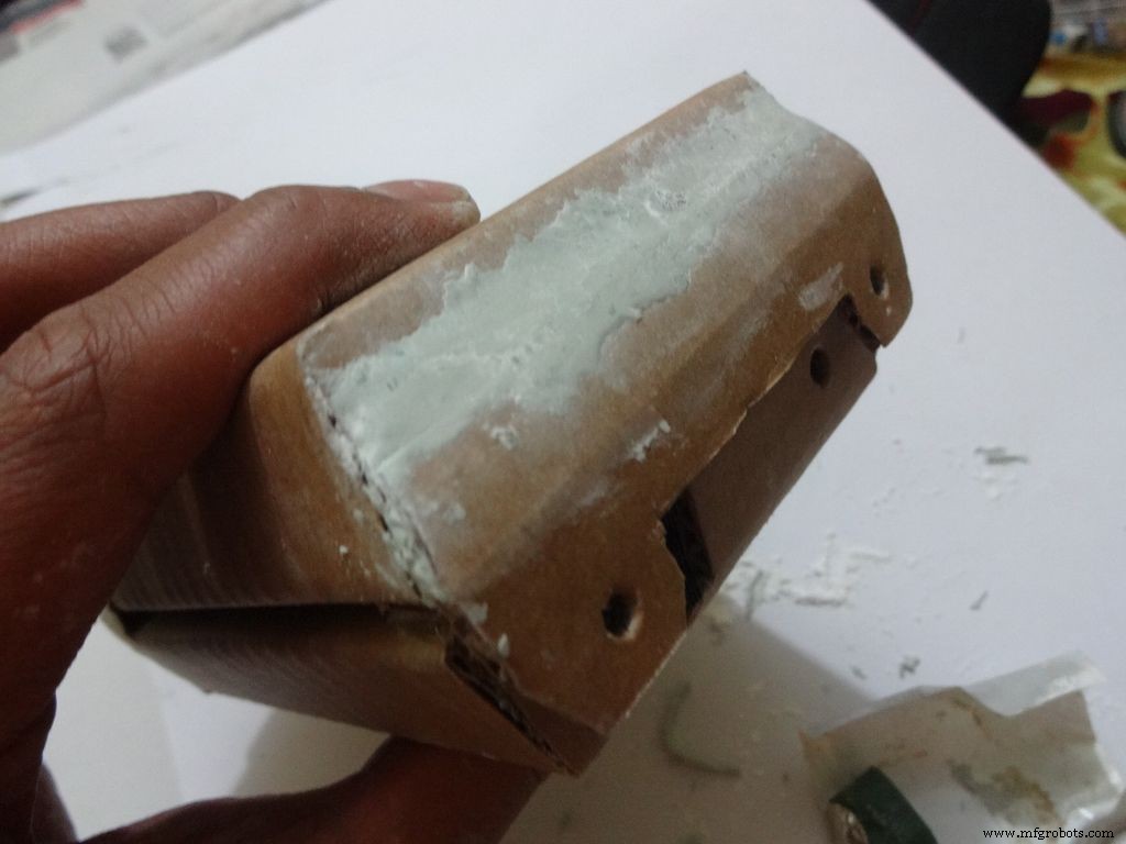
Step 13:Making the case - Final flaps
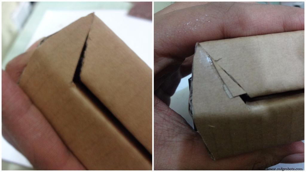
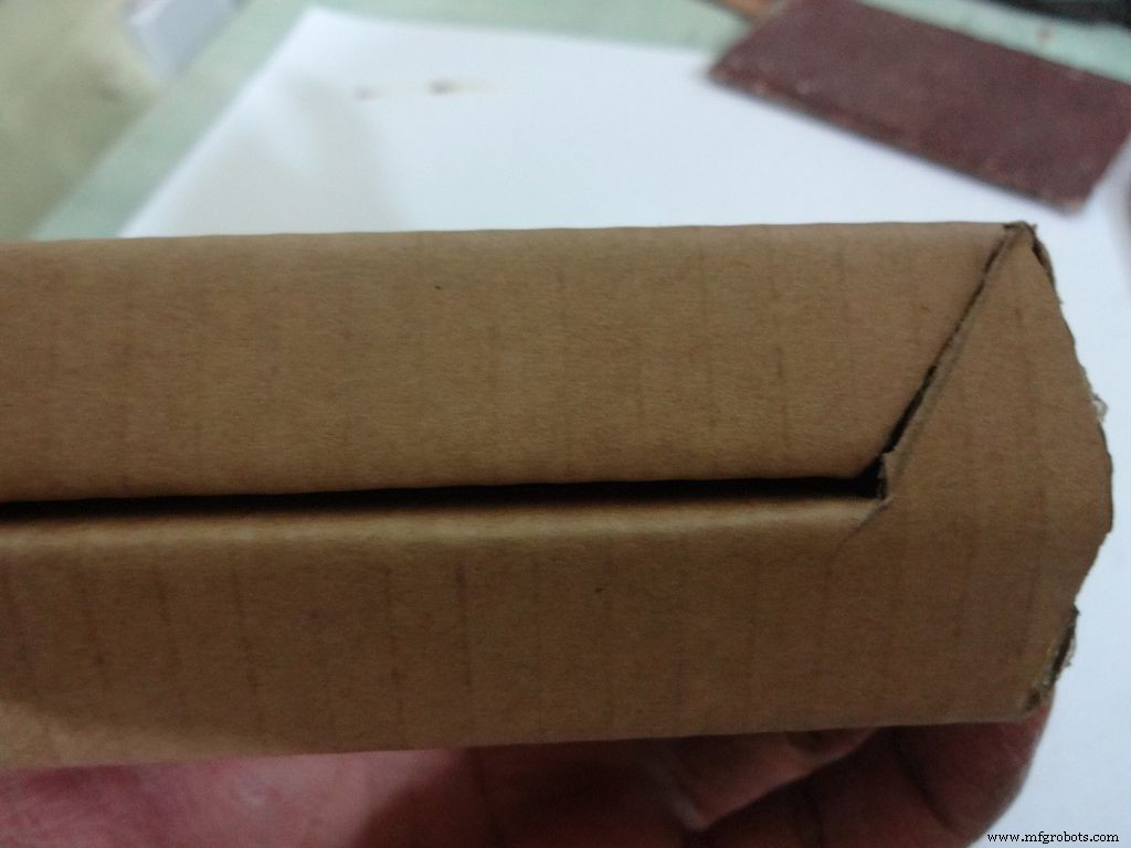
Sand, trim and close the tringular flap.
Make a small piece as shown and stick it to the cover. Make two holes, widen them with a pencil for inserting the bolt and locking the cover to the base.
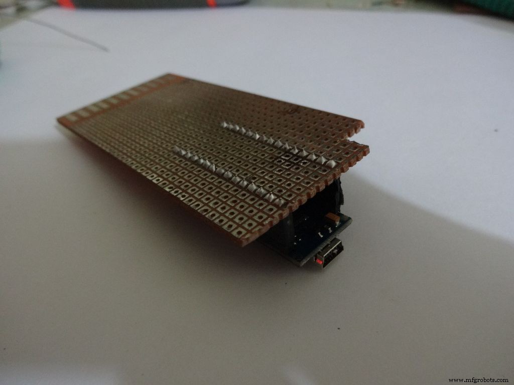
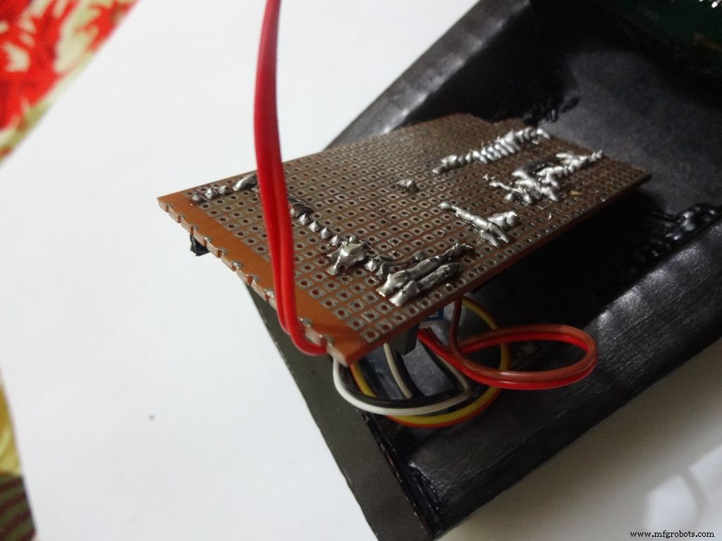
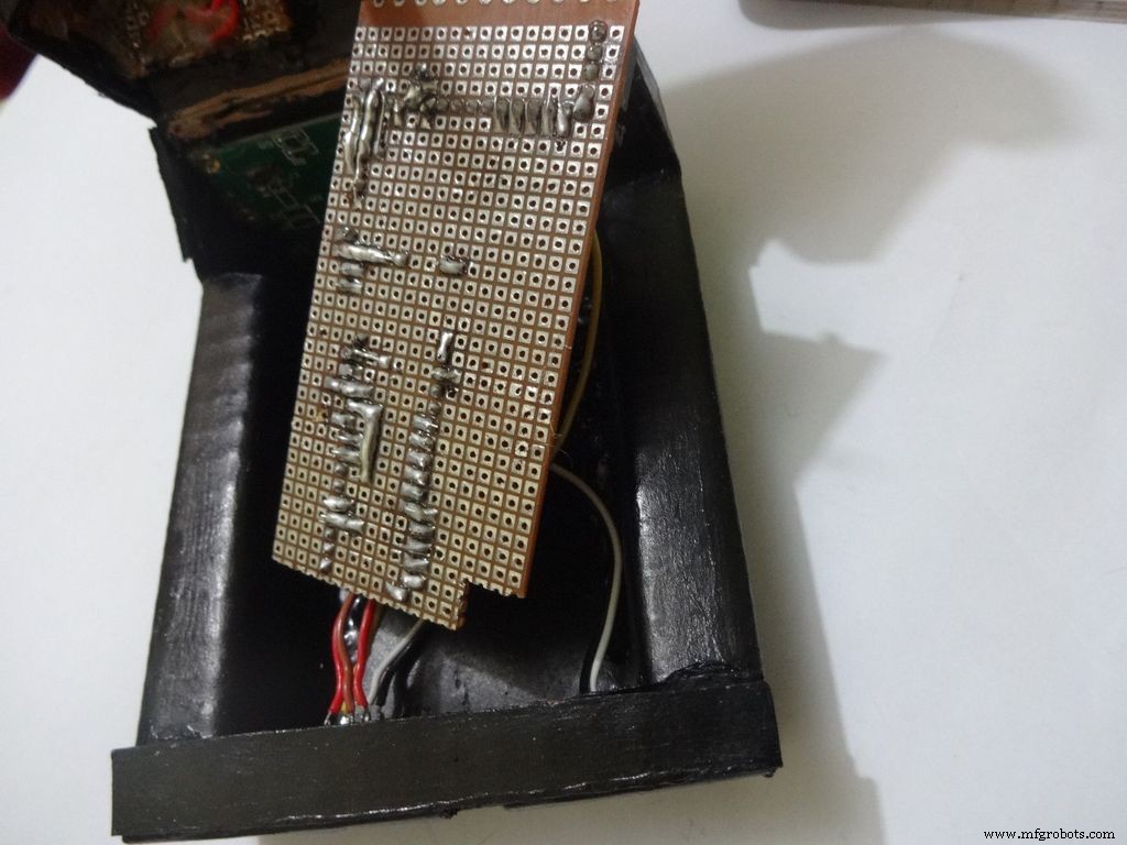
Step 14:The Circuit Board -- Making it fit

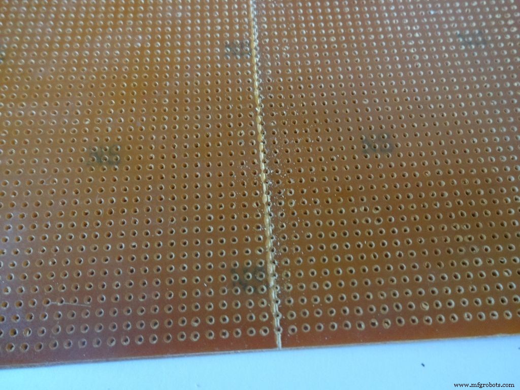
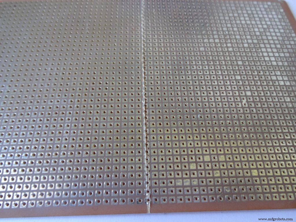
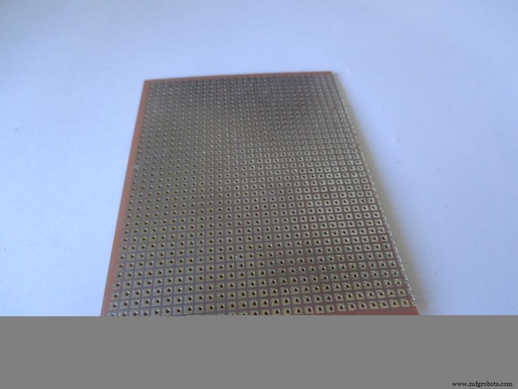
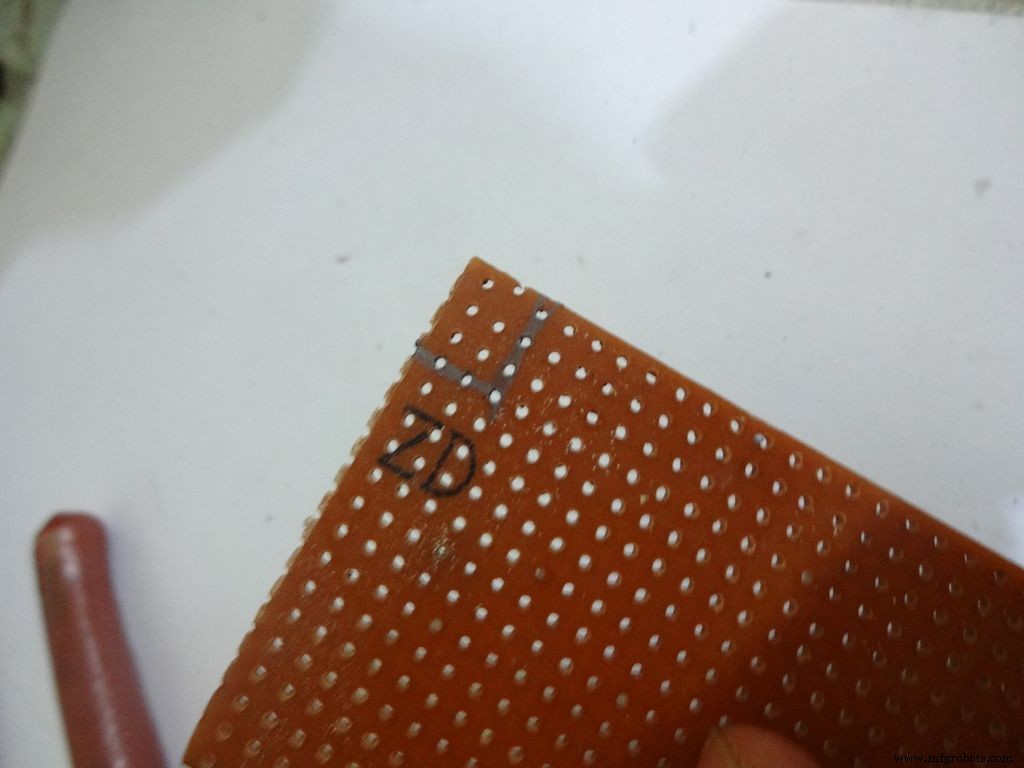
Cut the General purpose PCB to the right size such that it fits properly in the case. Mine is 2x4inches. To cut it, use the ruler and cutter and swipe it multiple times on both sides and it breaks off easily then.
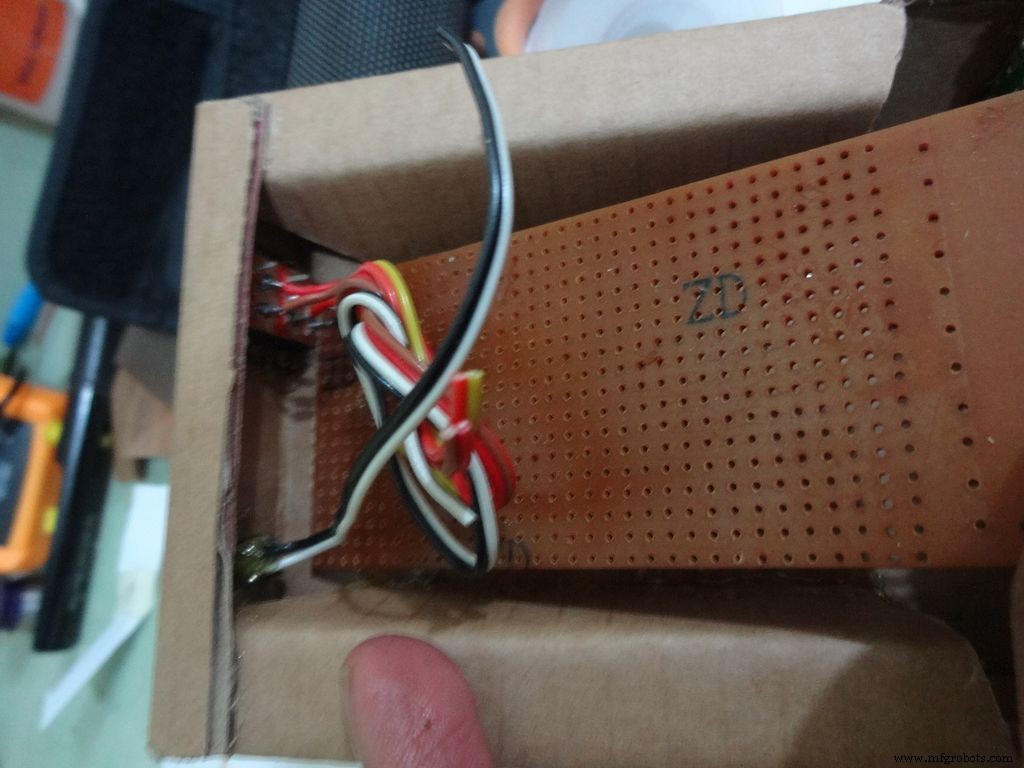
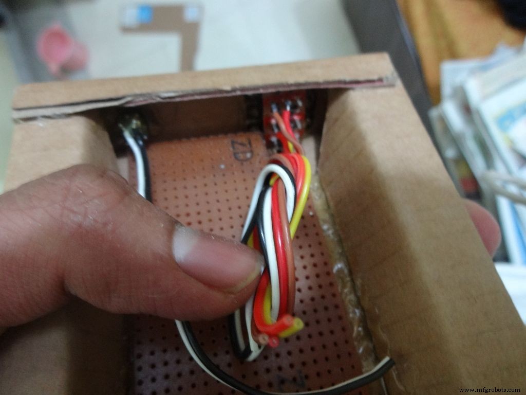
Place it inside. If the glue from the side flap lifts the PCB up, reheat the glue to flatten it or lessen the size of PCB a bit.
Cut a small part so that the 3 switches fit in and PCB goes entirely inside.
Step 15:The Circuit Board -- Arduino Nano

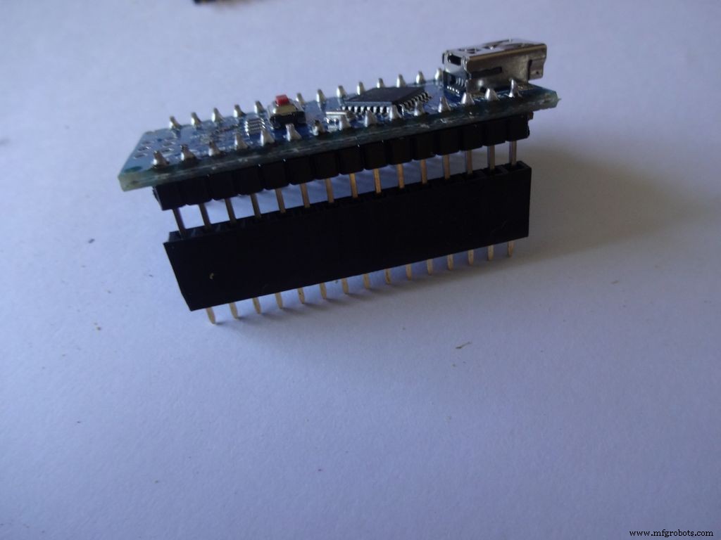
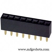
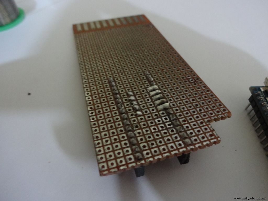
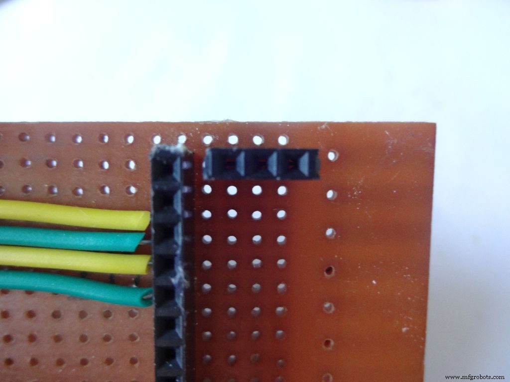
Cut female header pins of the right size for the Arduino.
Place it at the center edge of the PCB and solder all the pins.
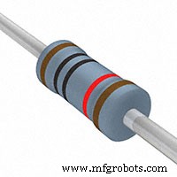
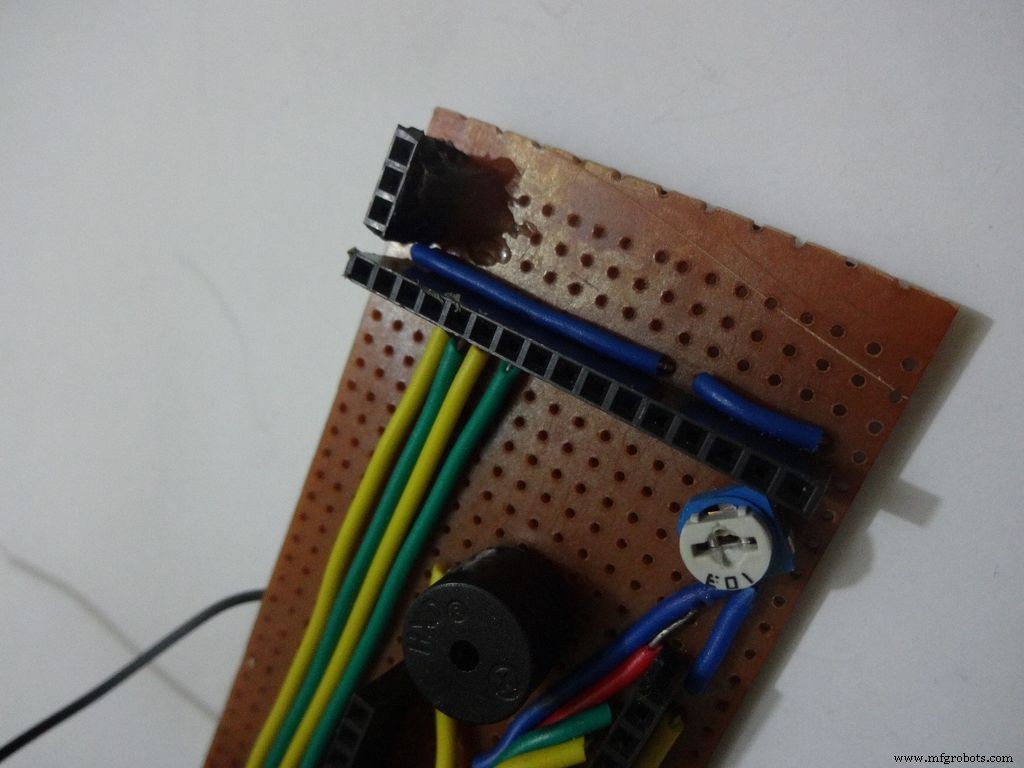
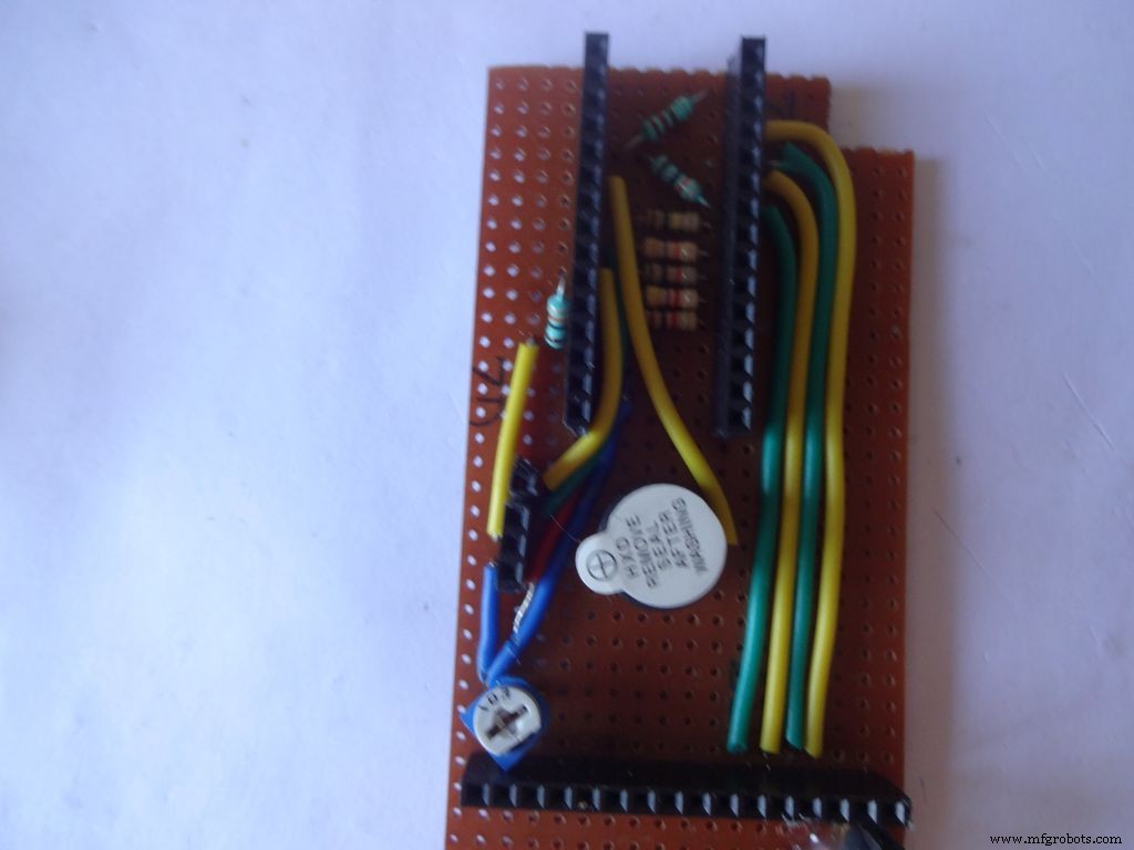
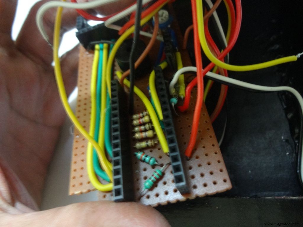
Step 16:The Circuit Board -- Ohmmeter
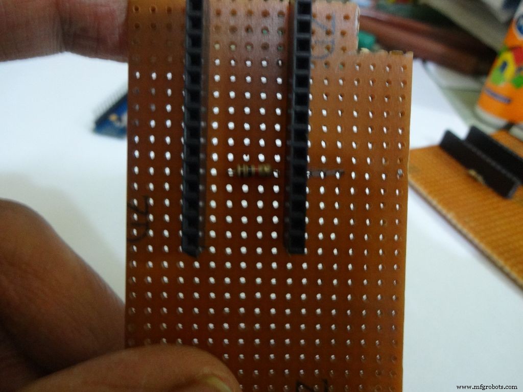
Before making any connections on the PCB please double check from the final Circuit Design.
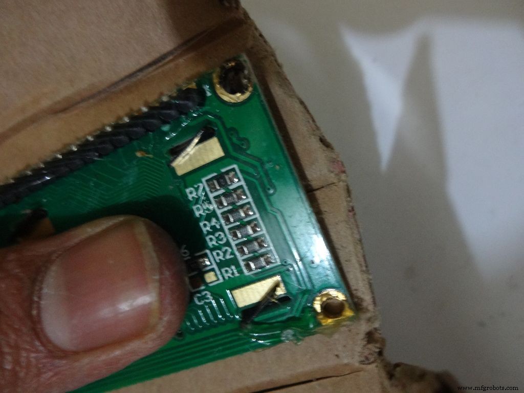
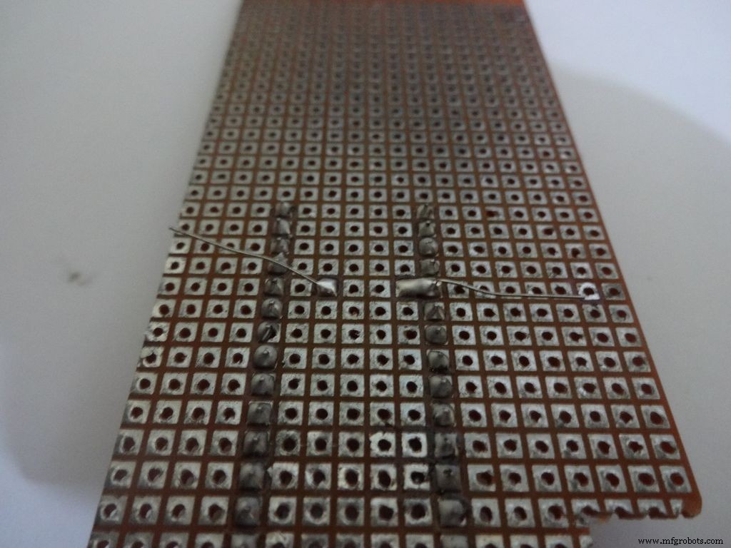
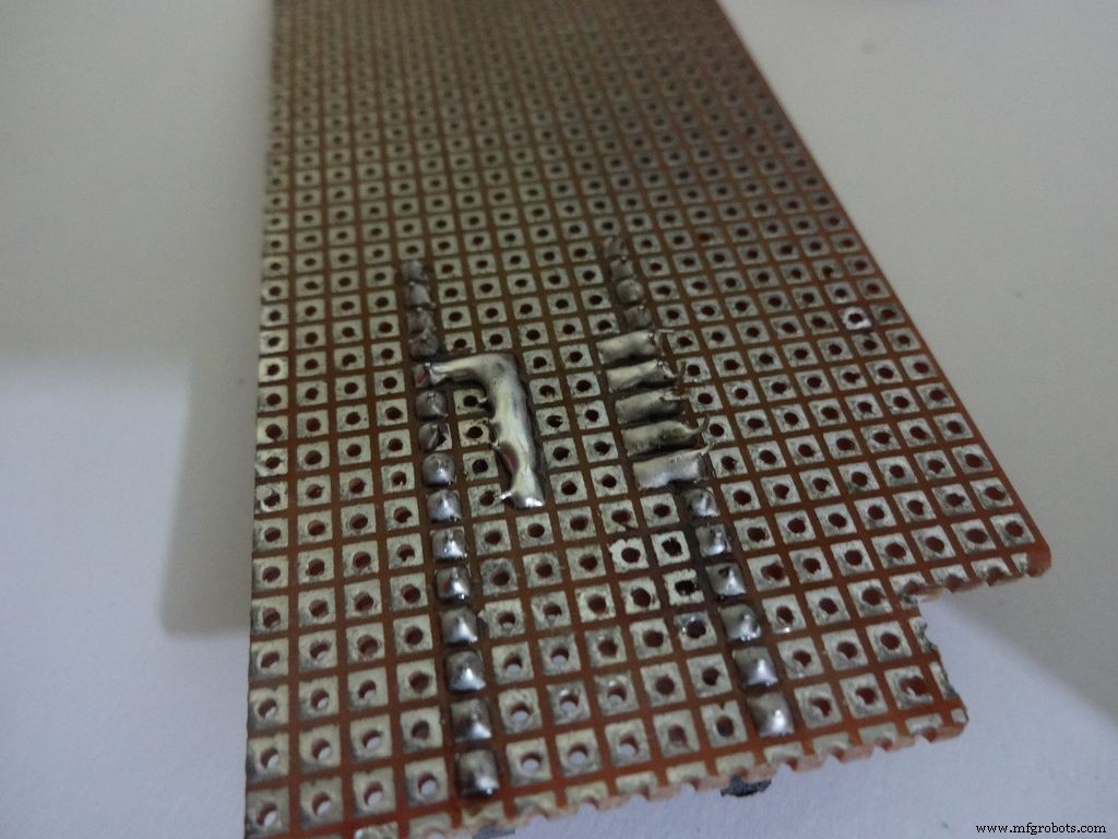
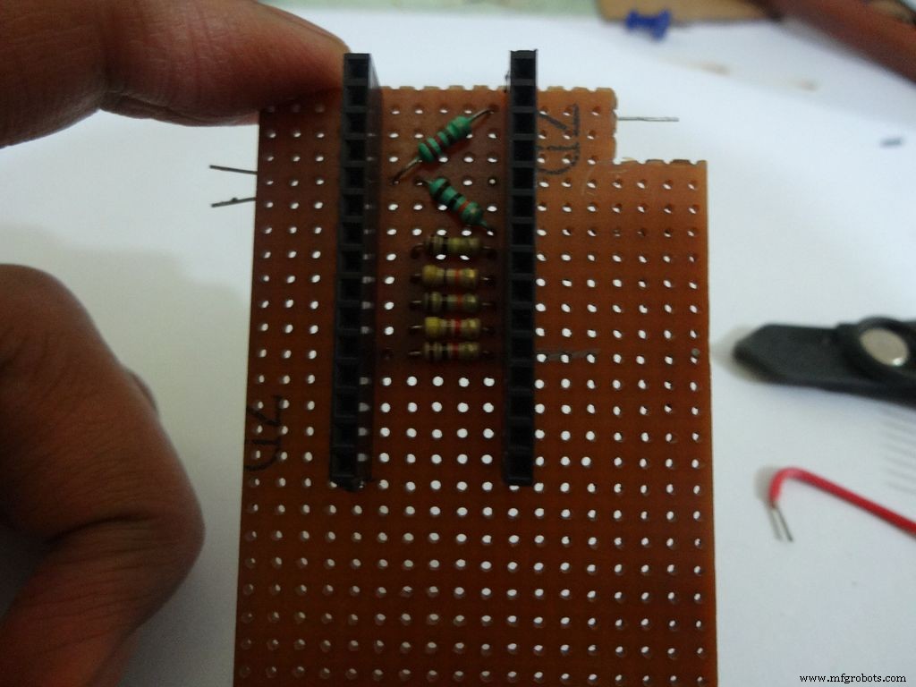
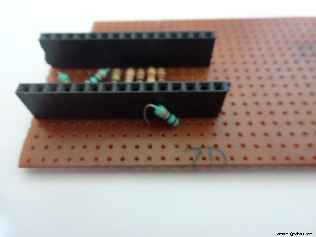
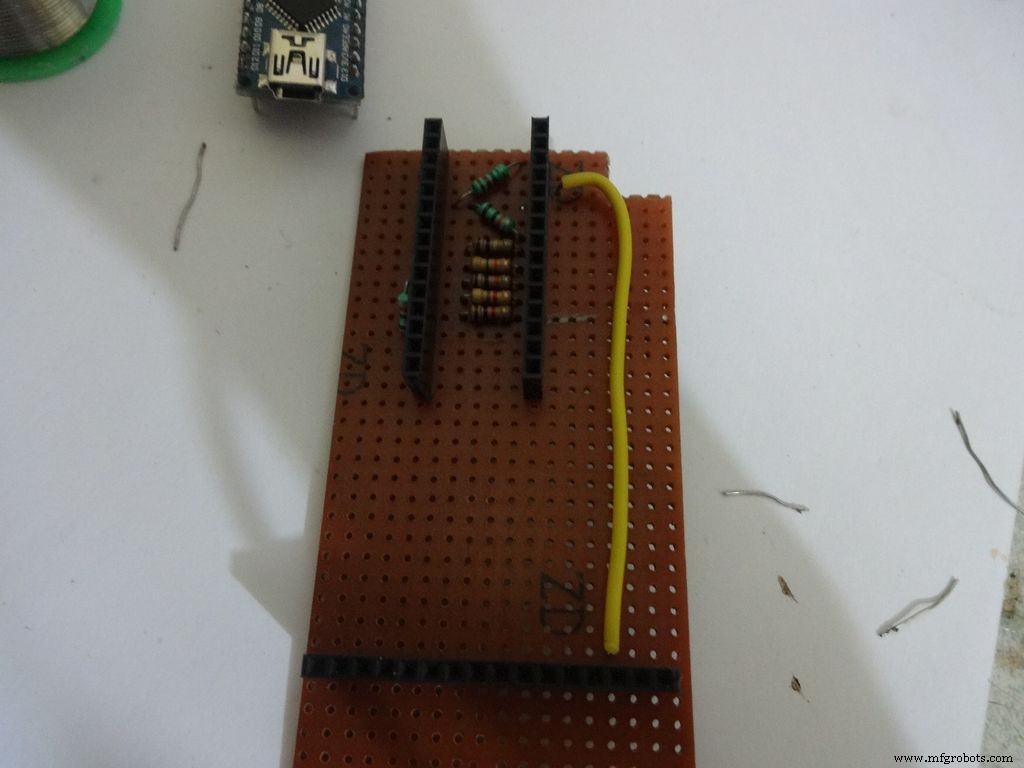
For the ohmmeter start by adding a 1k Ohm resistor to pin D2 of arduino. Place the arduino and carefully mark the pin. On the reverse side, bend as shown and solder it.
Do the same with the other 4 resistors, 4.7k, 10k, 47k and 100k Ohm.
Note:keeping all the tolerance bands(gold band) on one side is a good practice, eg UP and RIGHT.
Combine the second ends of resistors and solder it to A7 .
Step 17:The Circuit Board -- Capacitance Meter and Diode Test
Capacitance Meter:
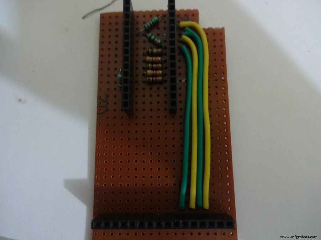
Solder a 220 Ohm resistor from D12 to A0 . And a 10k Ohm resistor from A0 to D7 .
Note: D7 (digital pin) is also used for LCD data pin D4 .
Diode Test:
Solder the 10k Ohm pullup resistor from A6 to +5V .
Step 18:Making connectors for LCD
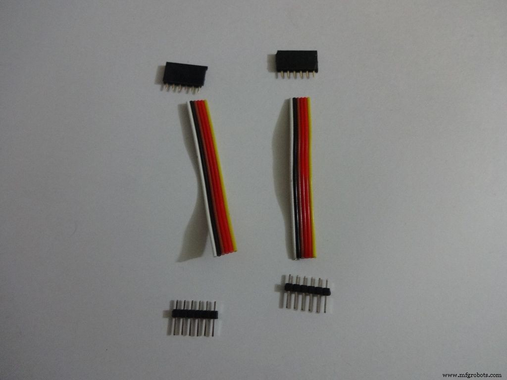
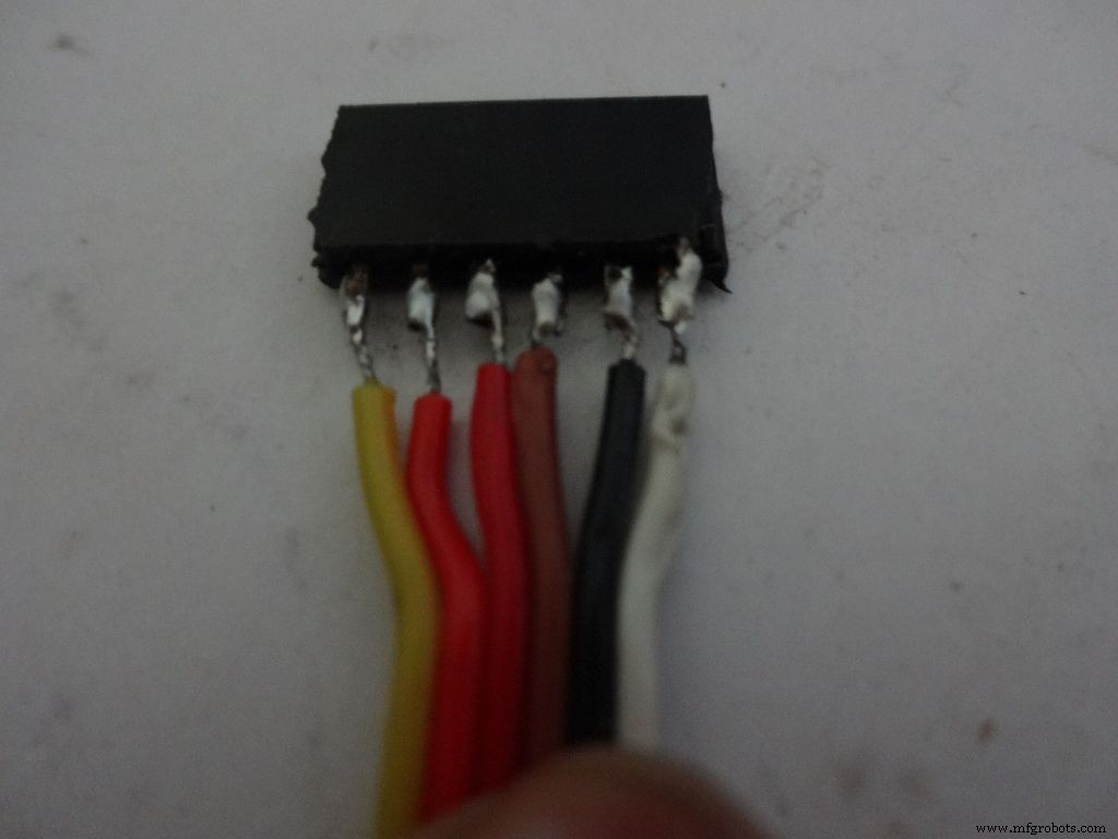
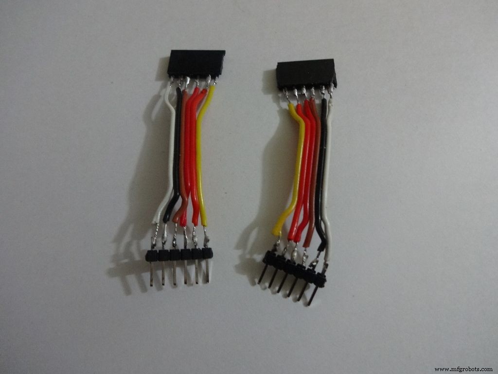
We just use the first 6 and last 6 pins on the LCD. Pins D0-D3 are unused. So we will be making connectors for only the used pins. It is recommended that you do the same because plugging/unplugging a 16pin connector becomes very tough once the build is complete.
Cut 2x 6pin female and male header pins. Also take 6 wire ribbon cable, around 2-2.5 inches long.
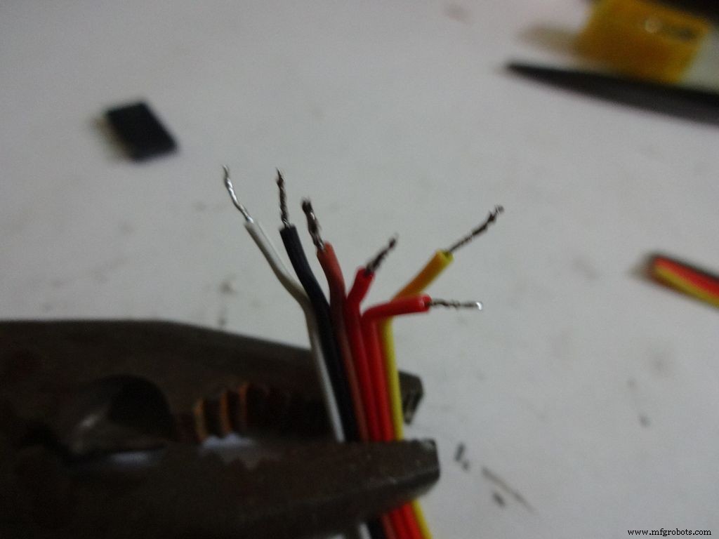
Strip the insulation and tin the leads. Also tin the header pins. Join them one by one just like the slide switches.
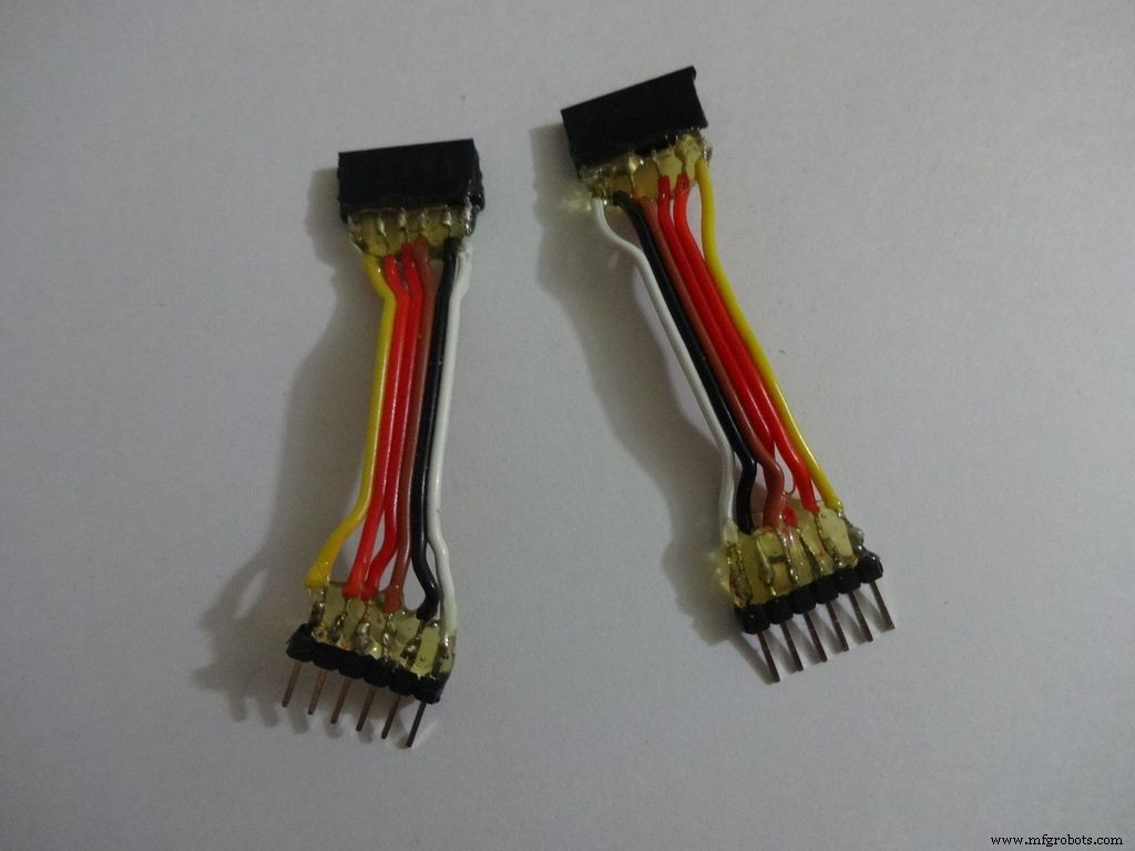
Apply hot glue to secure the wires.
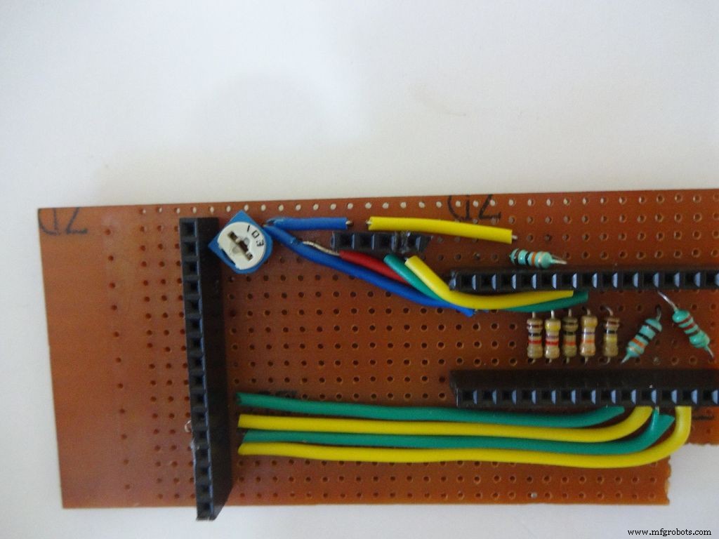
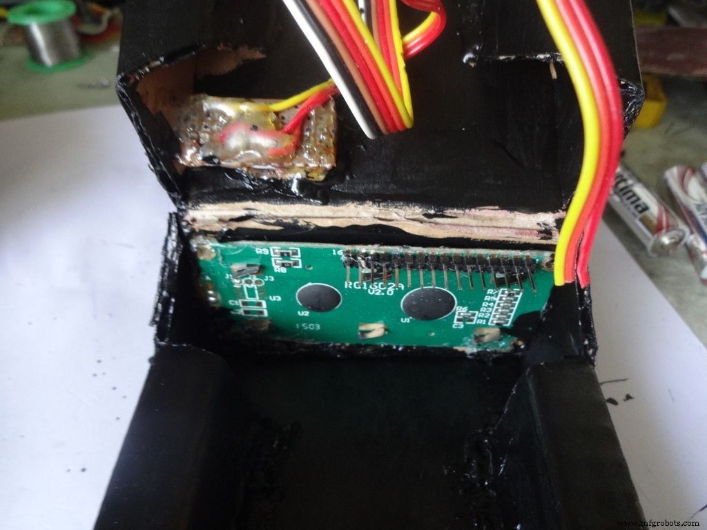
Step 19:The Circuit Board -- LCD connections
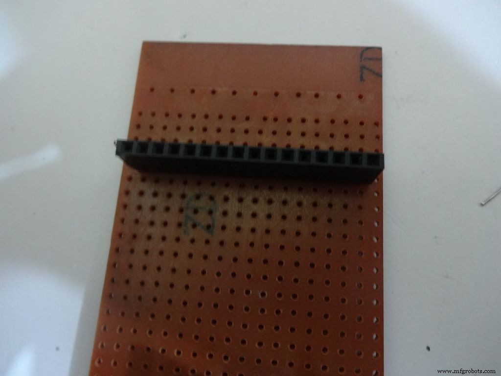

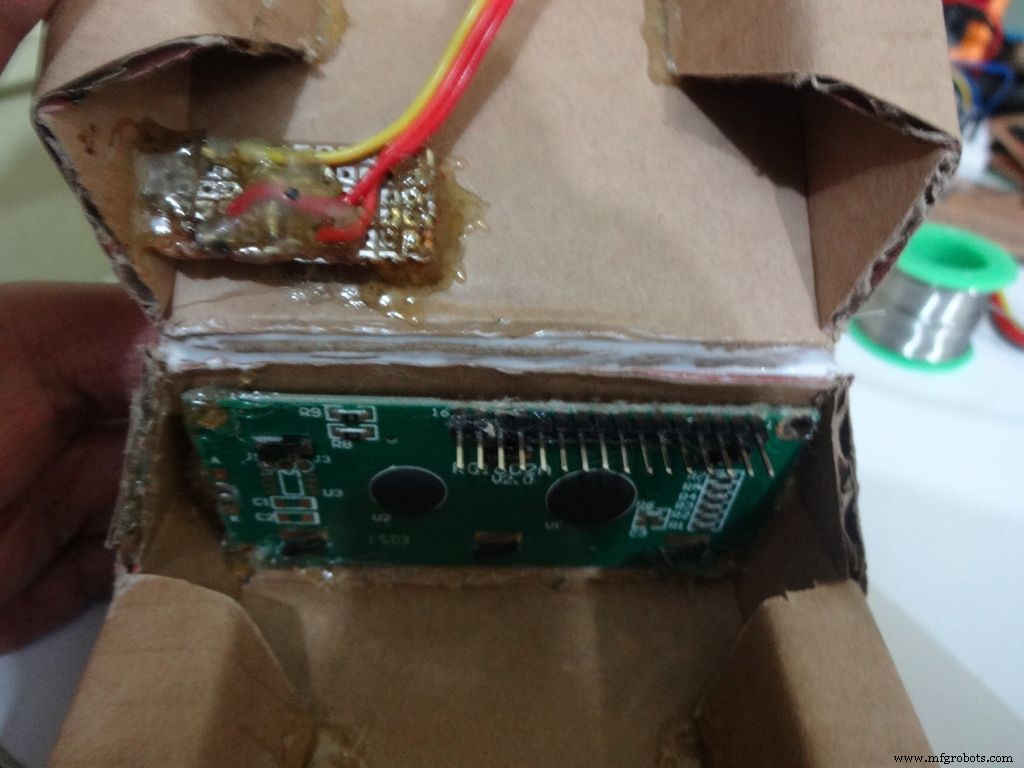
Place the PCB inside the case. Plug the connector to LCD and see where the female port should be on the PCB, solder it.
Make sure you leave 4-5 dot rows behind the LCD port. The Power switch will be added here later.
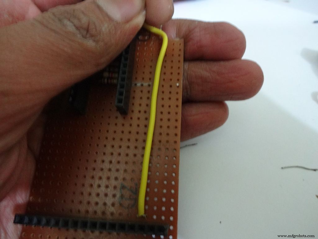
Measure the length of single stranded wire needed to connect data pins (D4 , D5 , D6 and D7 ) on the LCD to digital pins( D7 , D8 , D9 and D10 ) on the Arduino, respectively.
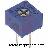
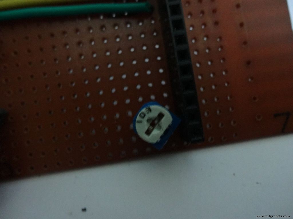
Add the 10k ohm potentiometer such that the side ends go to Vcc , GND and the middle pin to V0 .
Connect Vss(GND) on the LCD to GND , and Vdd to +5V . Also connect R/W to GND .
Arduino Pin
LCD
D7 D4 D8 D5 D9 D6 D10 D7 GND Vss(GND) +5V Vdd
Step 20:The Circuit Board -- RTC Module
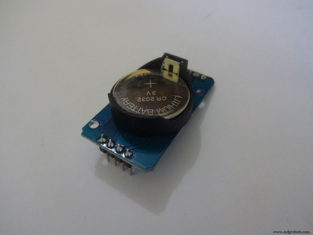
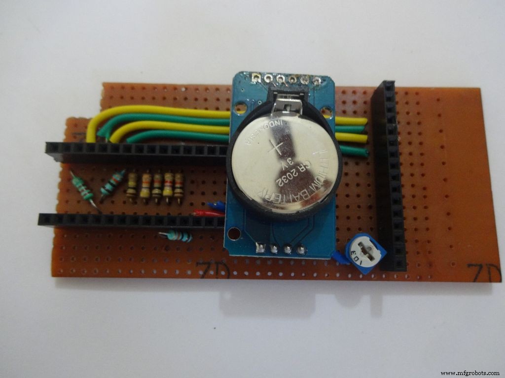
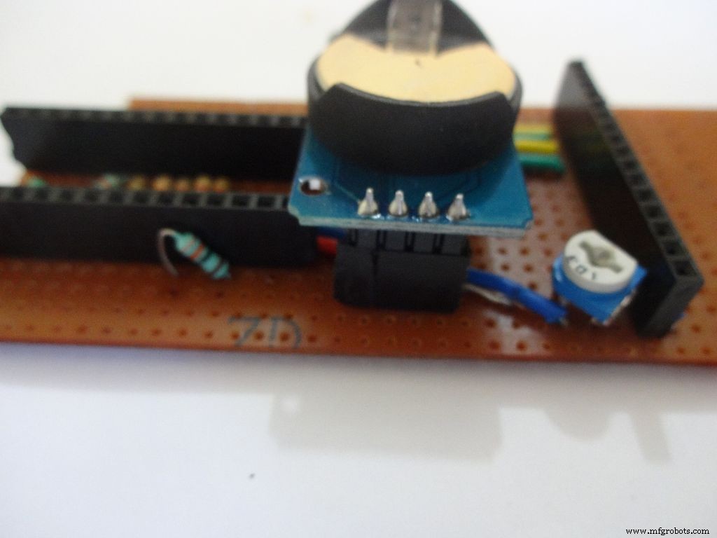
I desoldered the default 90 degree header pins on the module and added straight ones so that it fits flat on the PCB.
Solder 4pin female header pin and make connections to Vcc , GND , SDA to A4 and SCL to A5 .
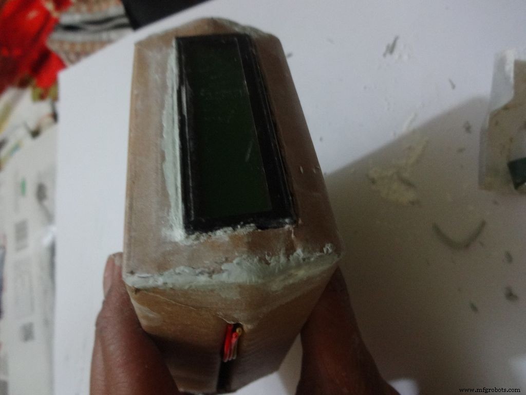
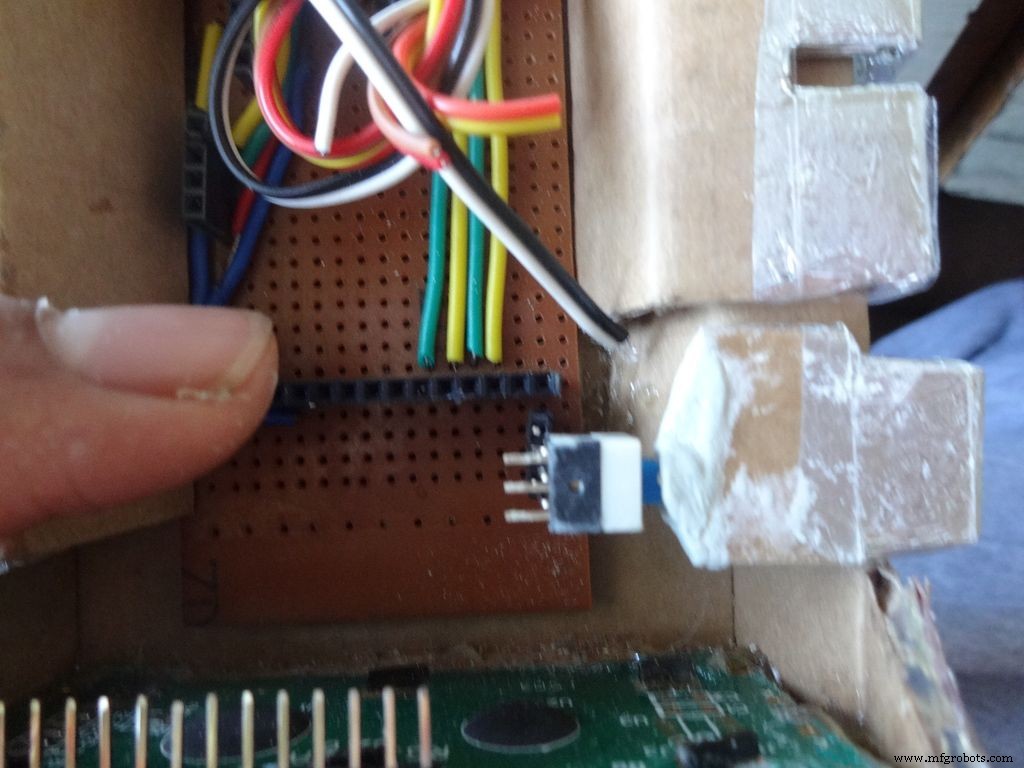
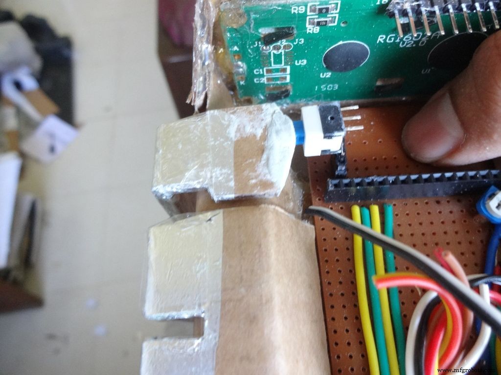
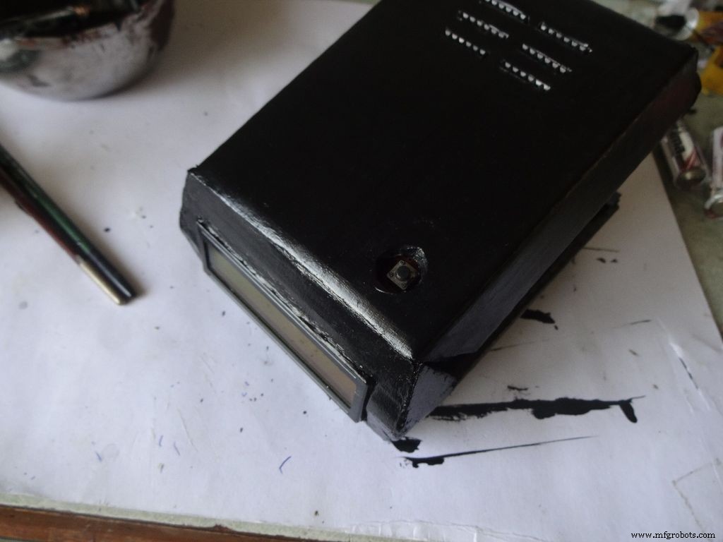
Step 21:Making the Case -- The mode button
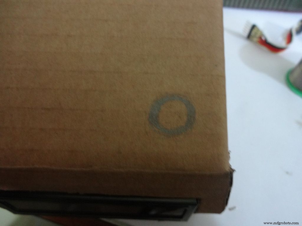
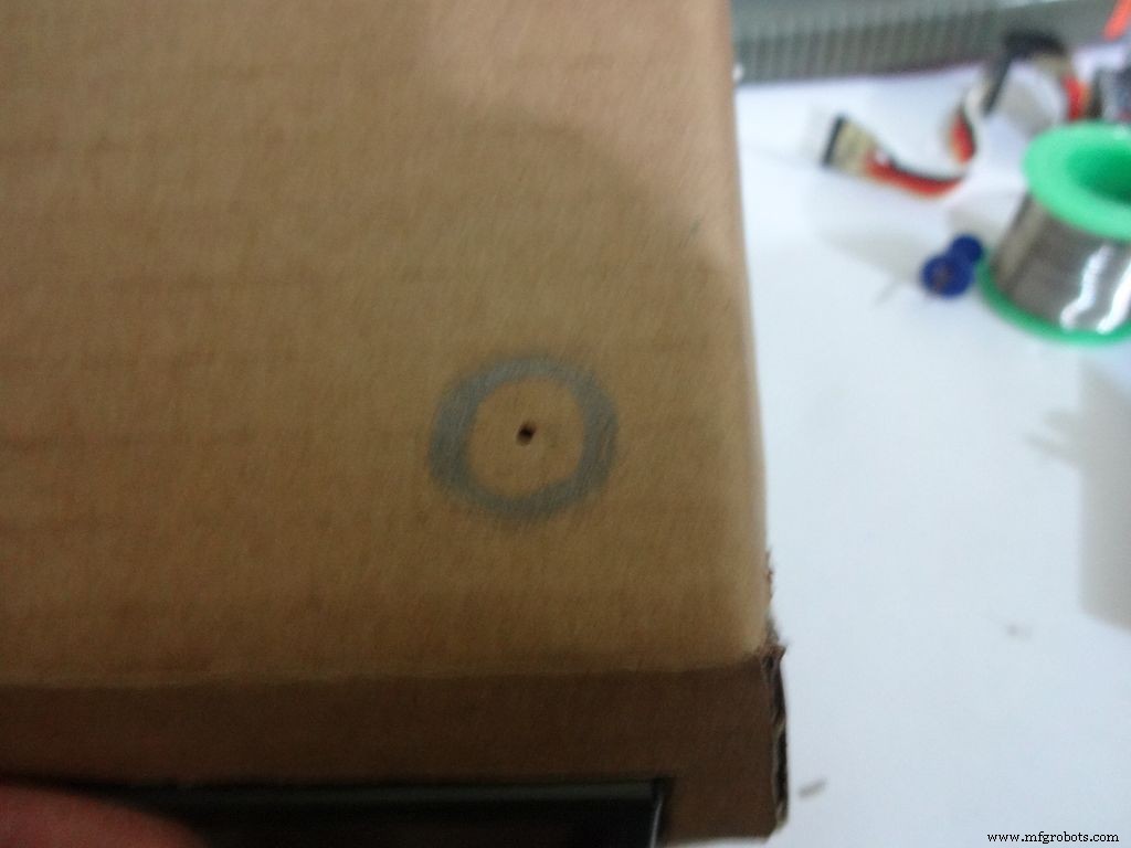
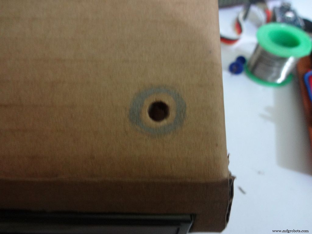
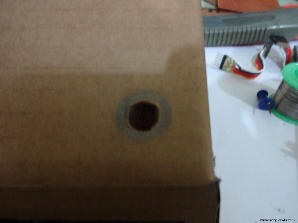
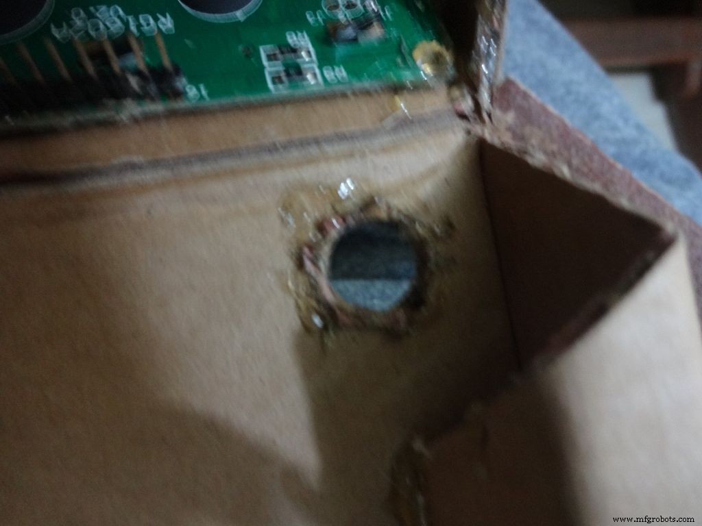

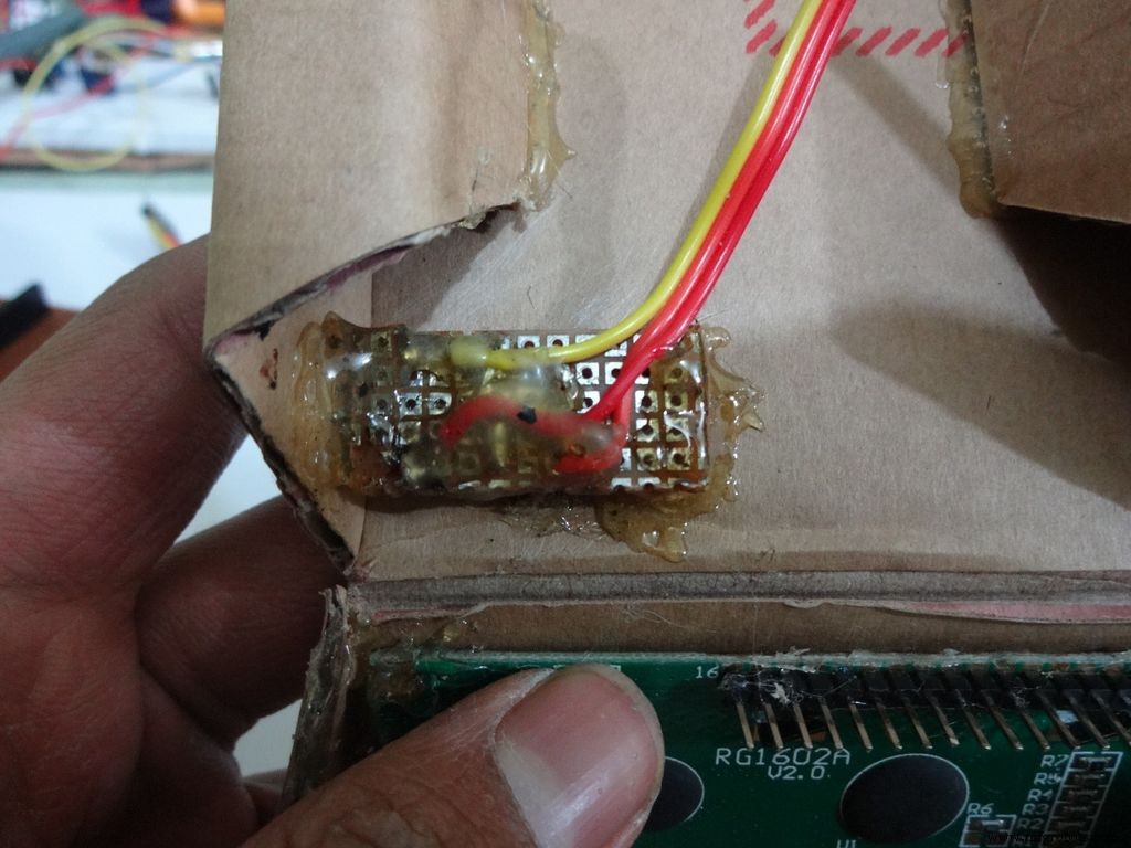

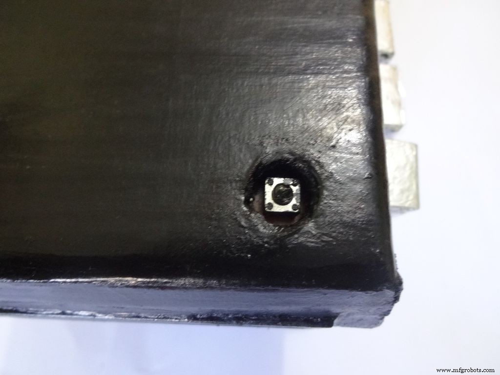
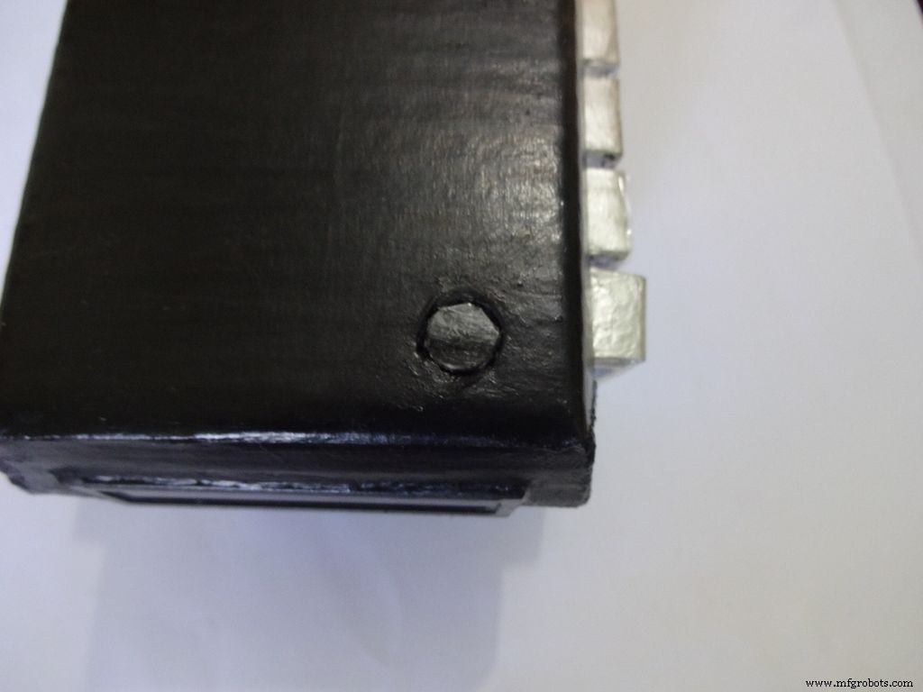
Mark a circle of about 1cm diameter at the pin1 corner of the IC case. mark the center with a pin, use a pencil to expand it. After that use some appropriate tool to increase the diameter to 1cm. Sand it on the inside and use hot glue to secure the hole.
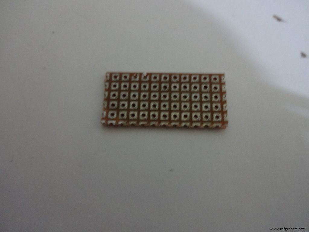
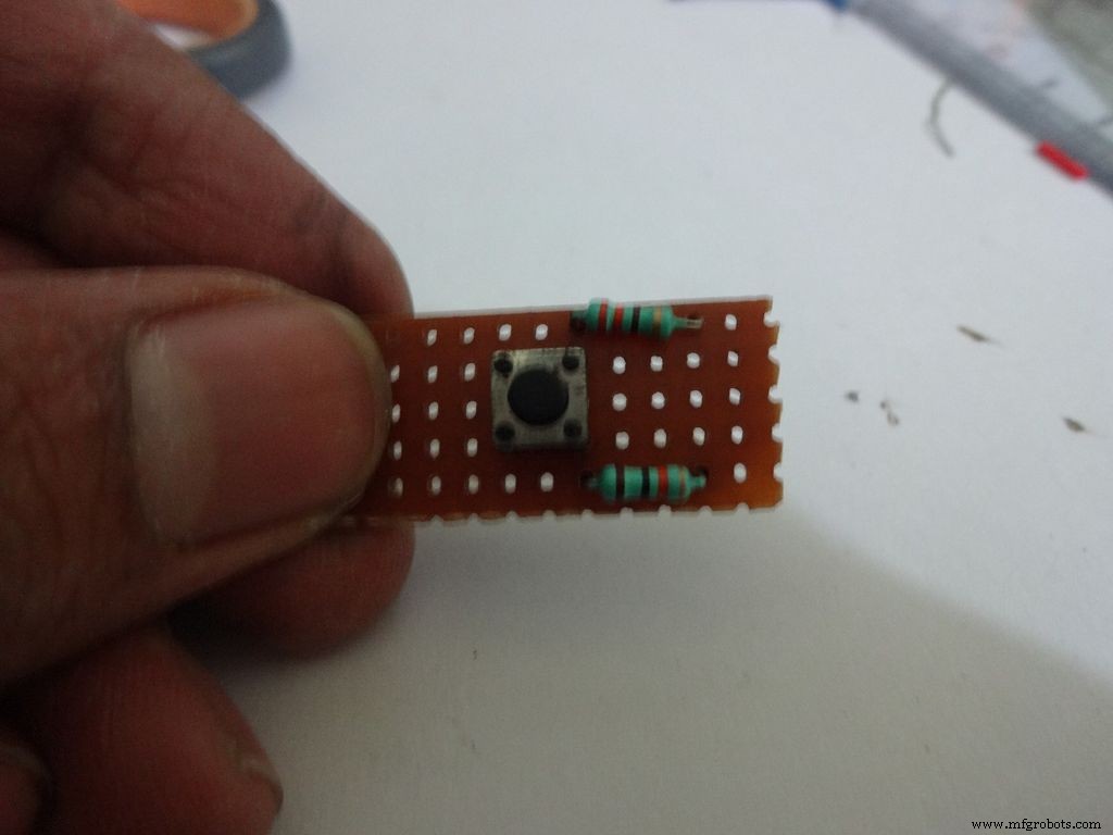
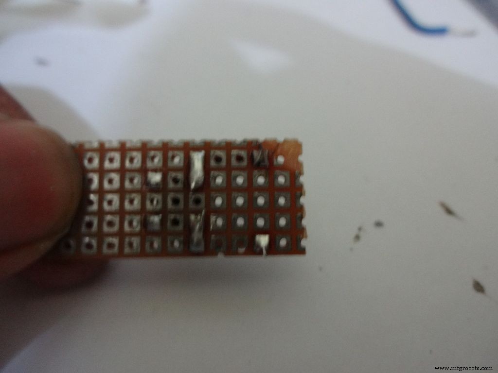
Cut a piece of General purpose PCB (10-11)dots x 5dots. Plug in and solder the pushbutton, 220 and 10k Ohm resistors as shown.
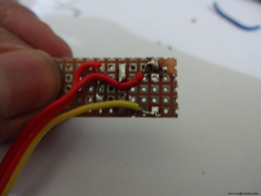
Take 3wire ribbon cable about 15cm long. Tin the ends and solder it as shown. Note down which colour wire goes to where, this will be helpful later on.
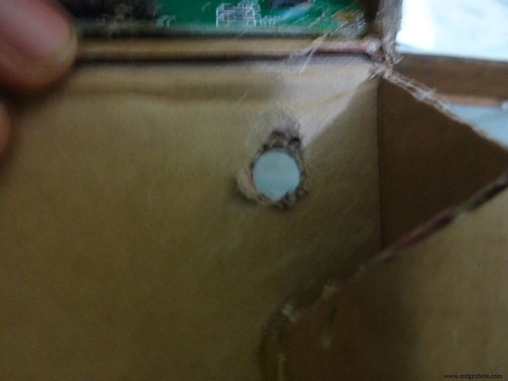
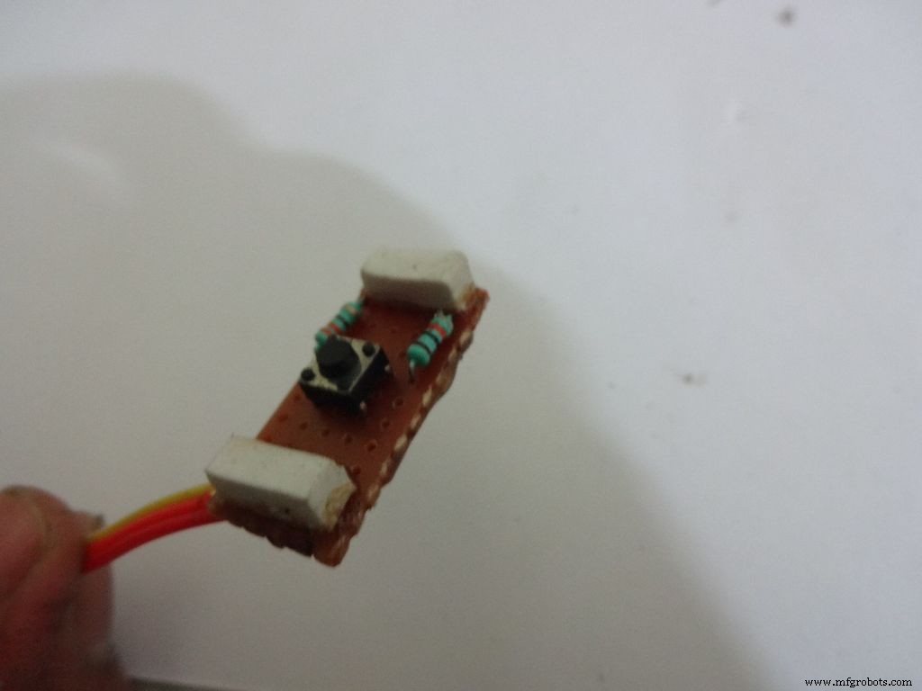
Cut 2 small pieces of eraser and place it on the ends on the board. The height of the eraser should be such that the button is below the cardboard inner level as viewed from outside. I used 4mm.
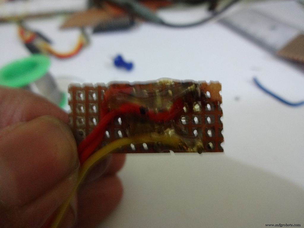
Secure it with hot glue as shown
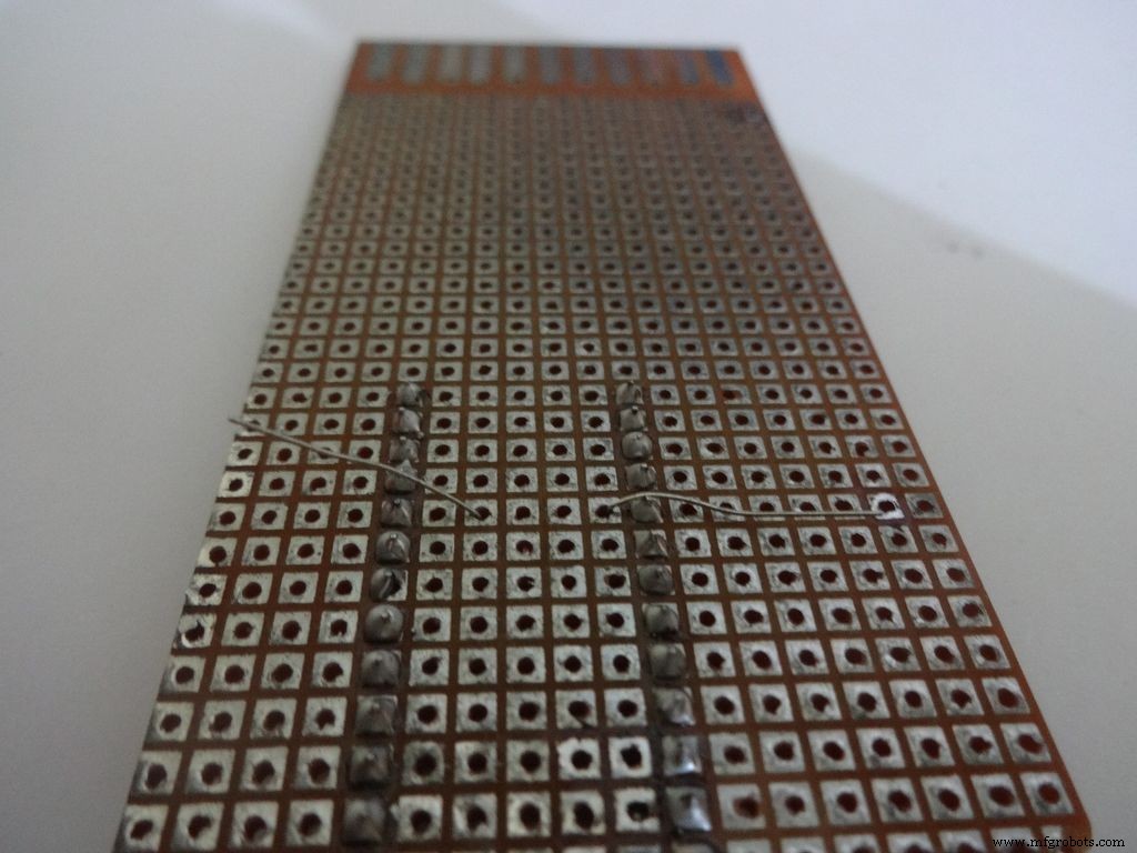
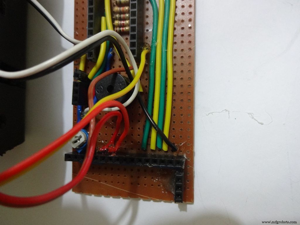
Step 22:Making the Case -- Testing points
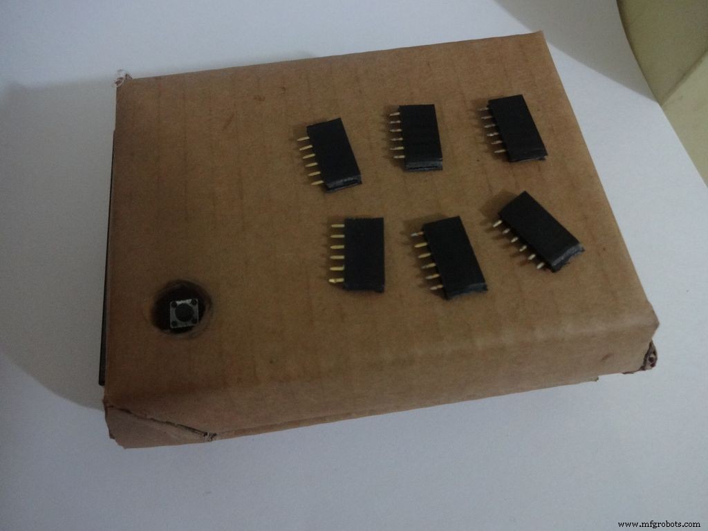
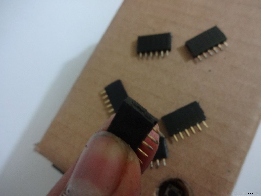
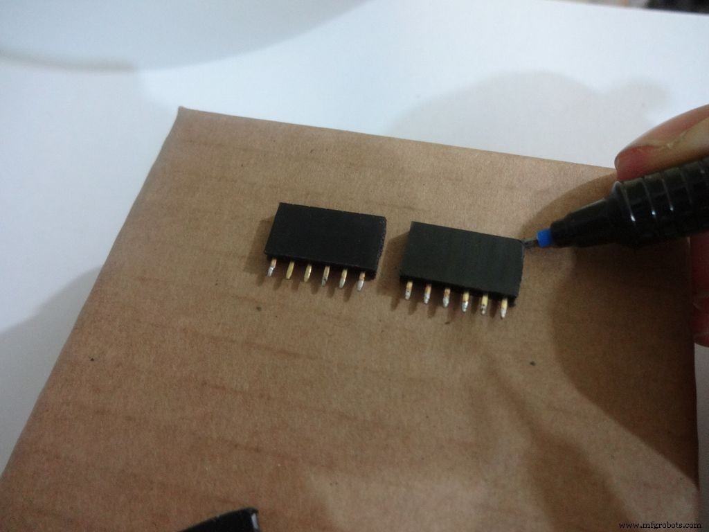
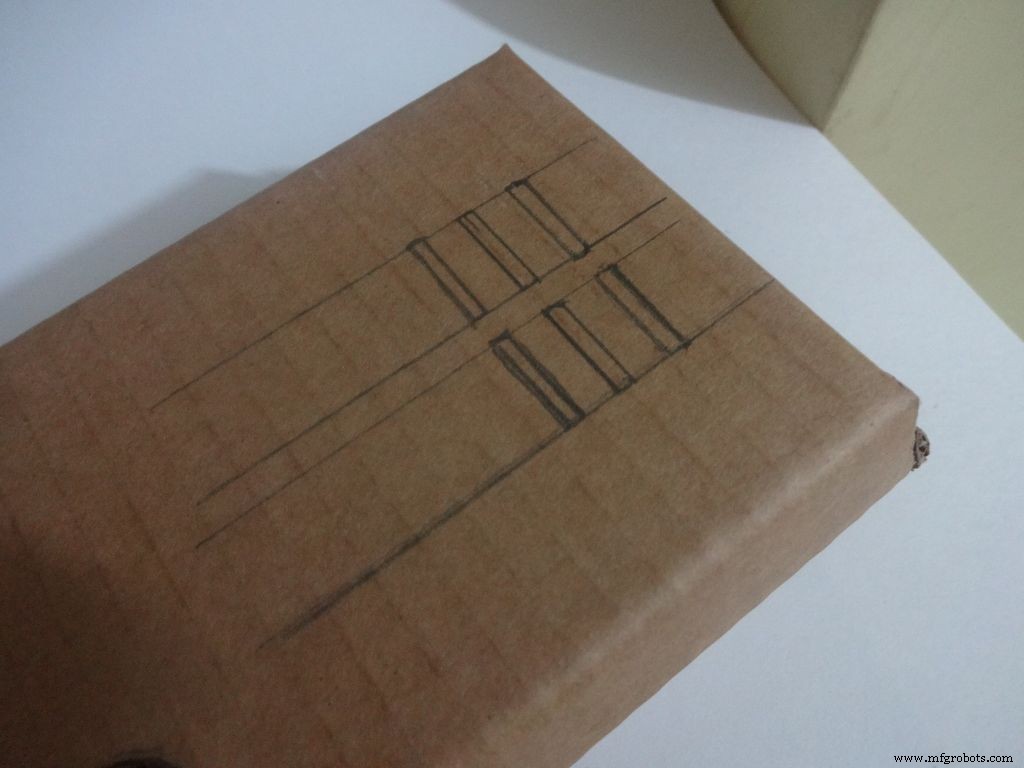
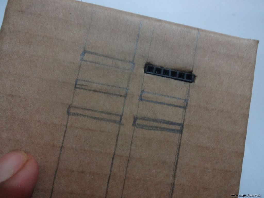
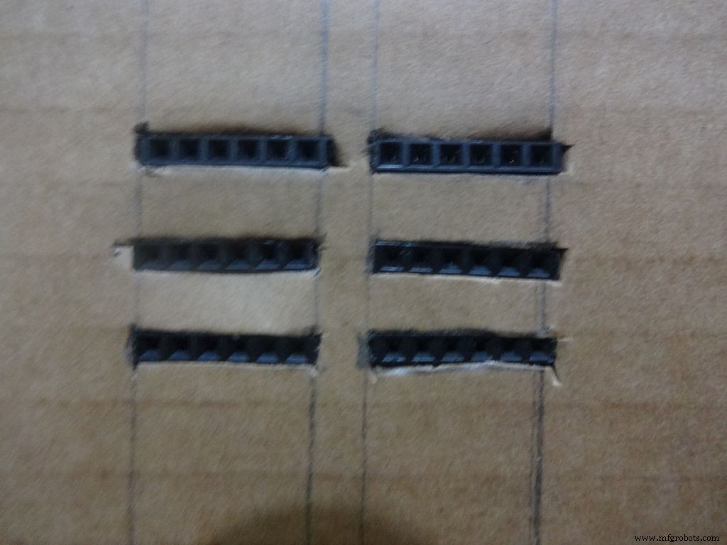
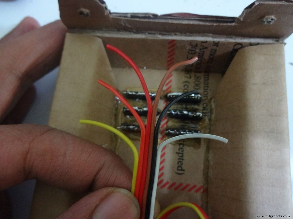
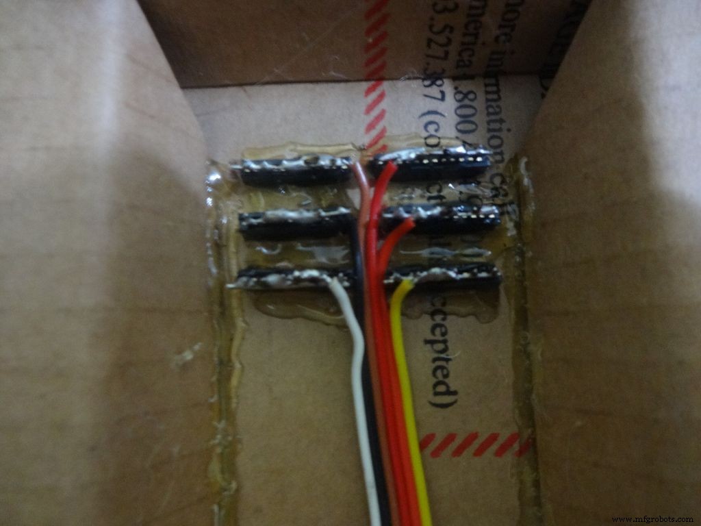
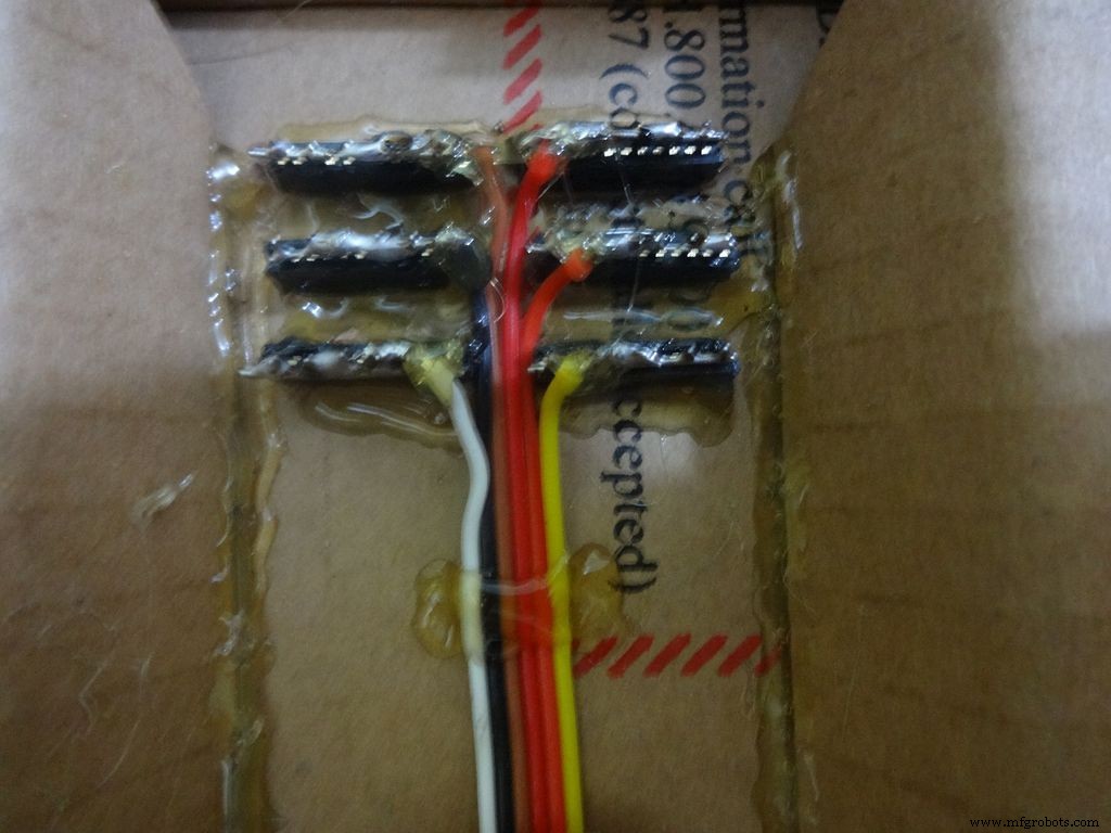
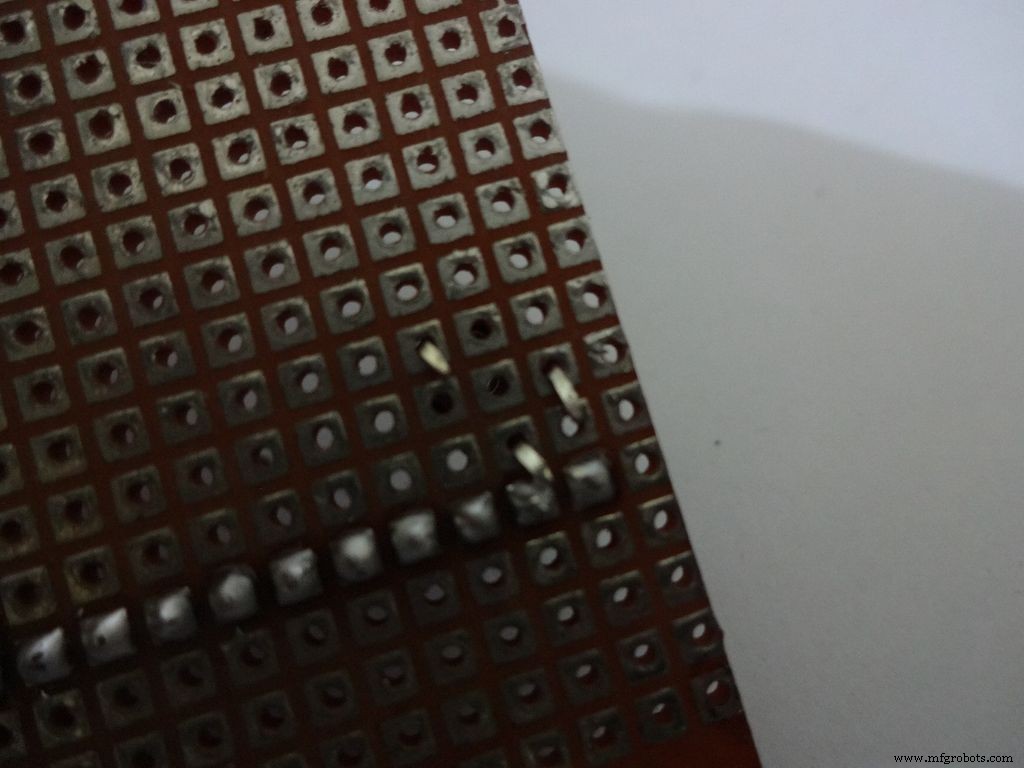
Cut 6x 6pin female header pins. Sand the sides to make it smooth.
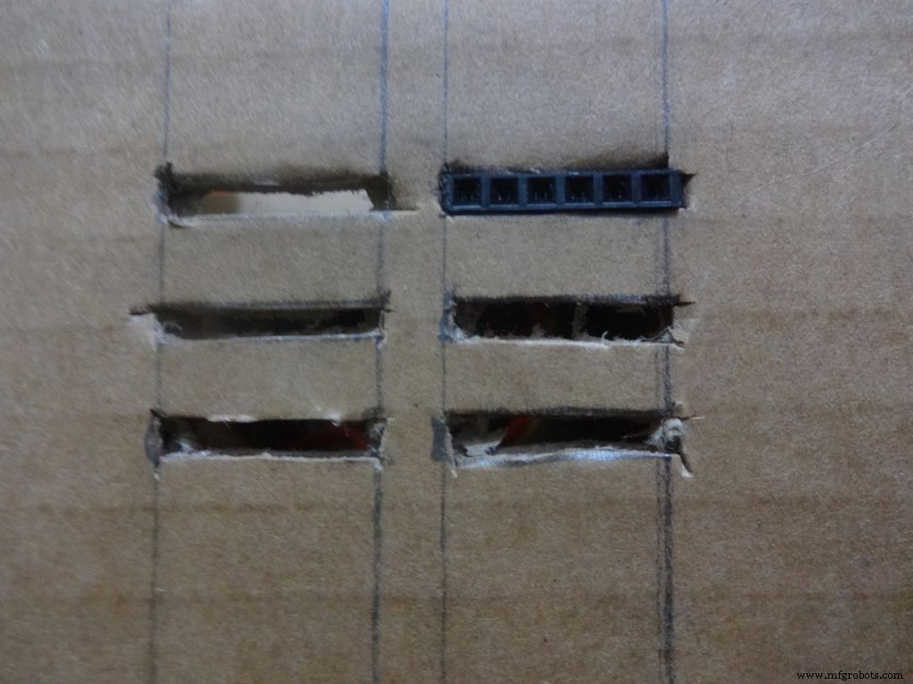
Mark the positions and cut slots for the header pins. Insert it in place and glue it from the inside.
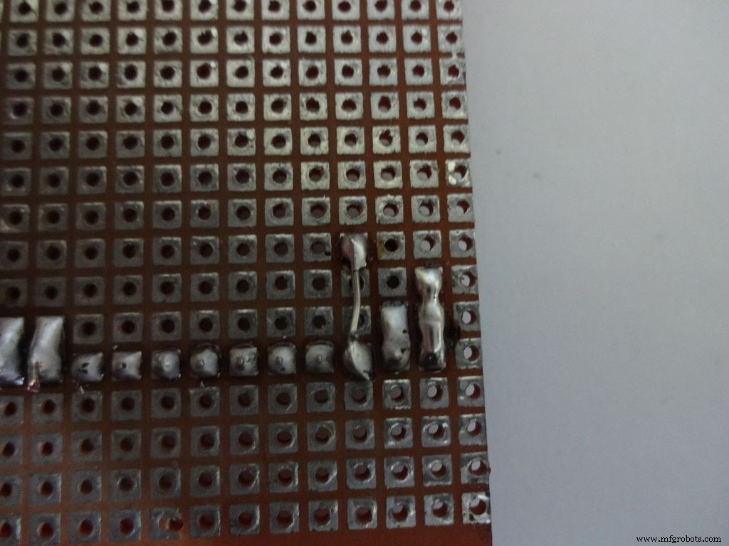
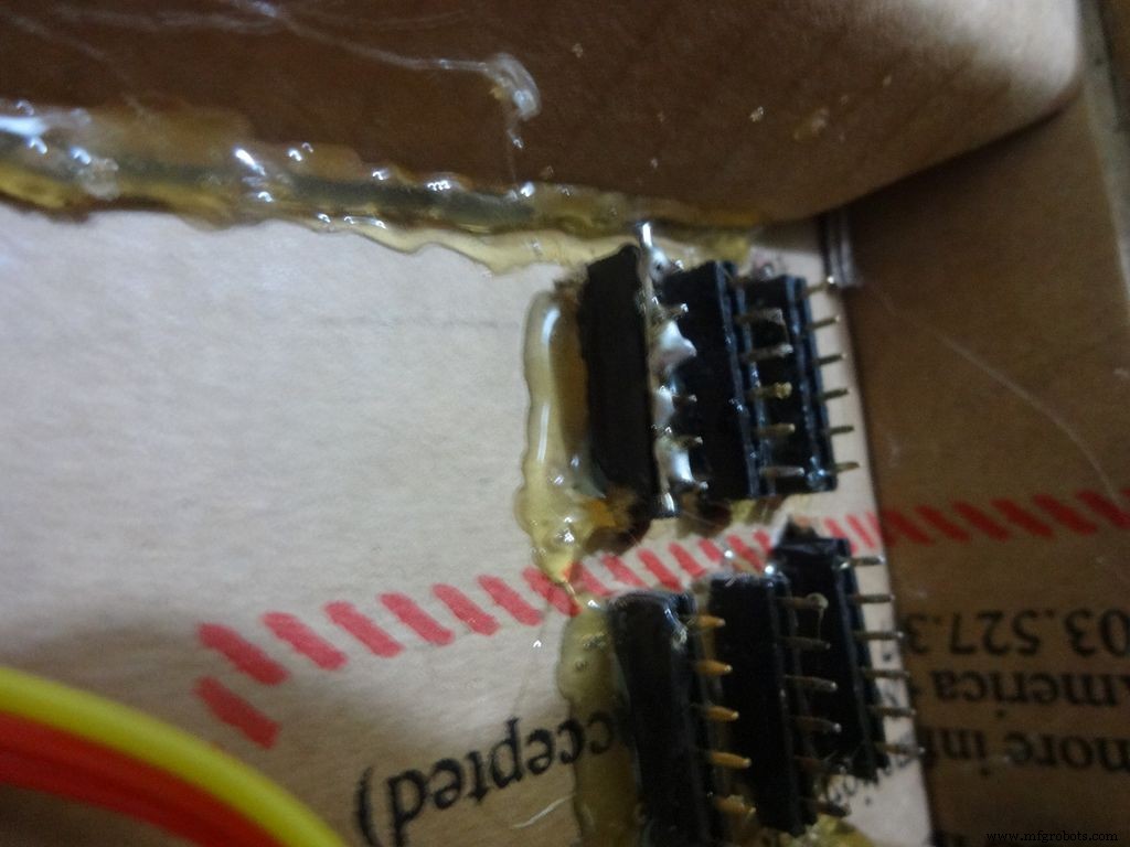
Apply small amounts of solder to all the pins and use a stripped jumper to get it all together. Make sure all of them are connected. Dont keep on heating it to make it perfect. Heating a pin also heats the neighbouring ones.
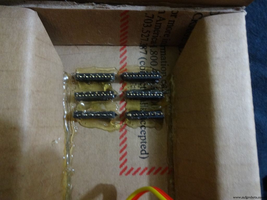
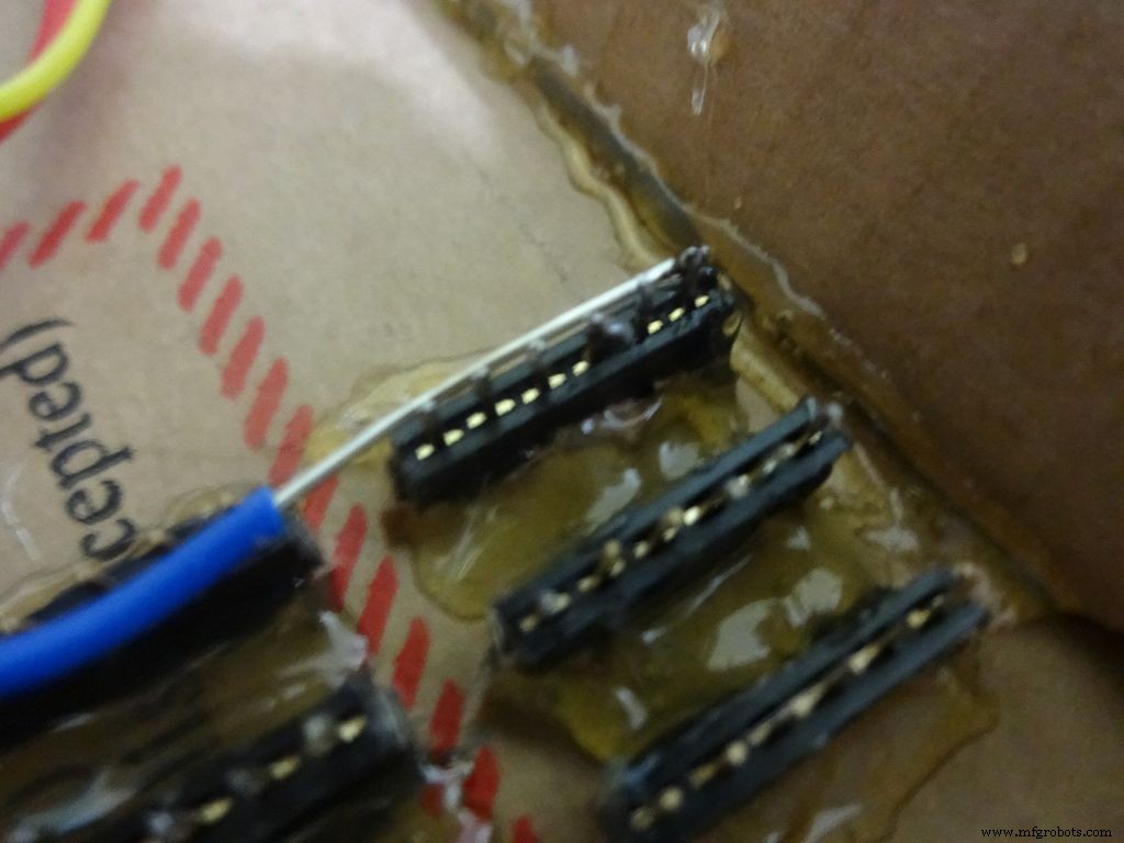
Take 6 stranded ribbon cable, tin it and attach it to each slot. Note that I put dark colours to the negative side. Apply hot glue to fix them in place.
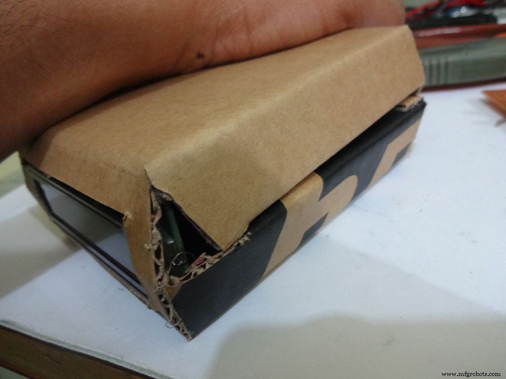
Step 23:The Legs


Download "Legs_A4.pdf" or ""Legs_ANSI_A.pdf", based of paper size available in your region. attached at the end.
Print it on an A4 size paper (21 x 29.7cm or 8.27 x 11.69 inches) or the US-alternative ANSI A(8.5 x 11inches or 21.6 × 27.9cm). Make sure that while printing you select the proper paper size, orientation, and select the "Actual Size" option. Confirm that the print is accurate by measuring the rectangle. It should be 8.4 x 11.8cm
Cut crease and glue it just like the main case, see the images.
Step 24:Making it shiny!
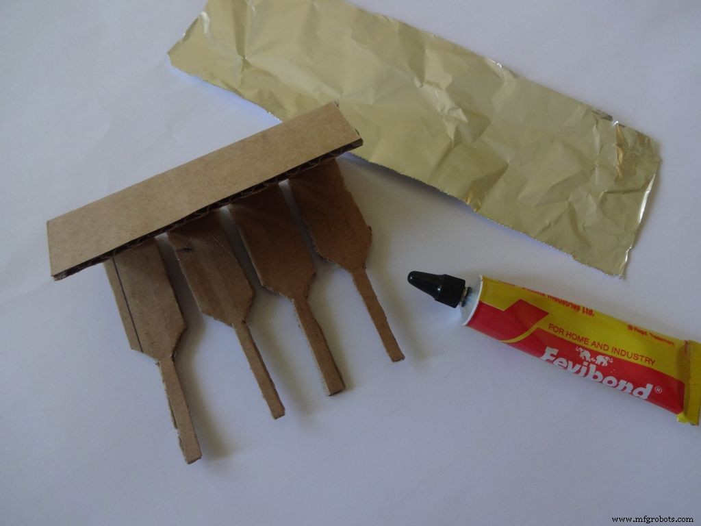
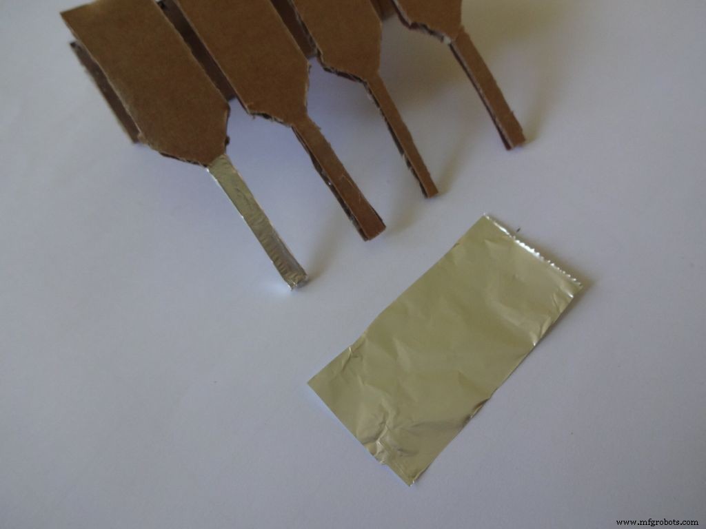
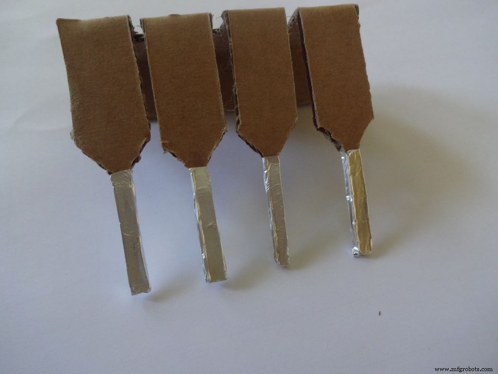
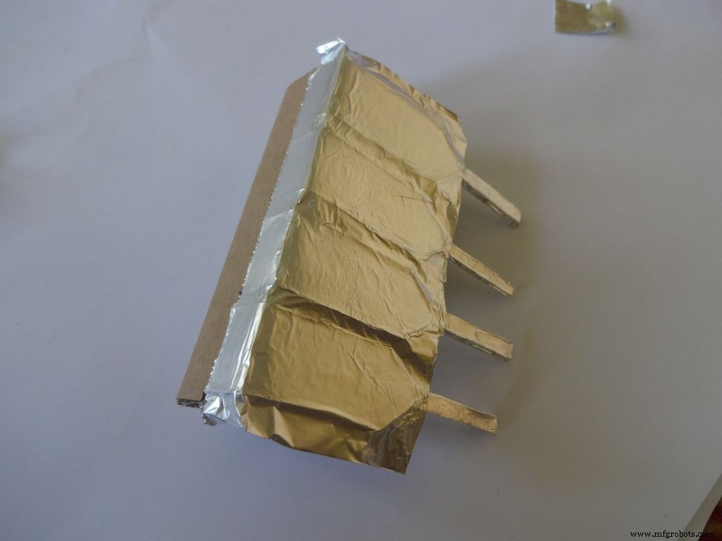
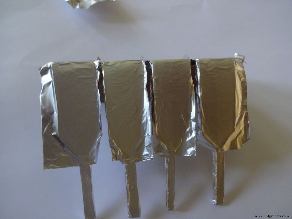
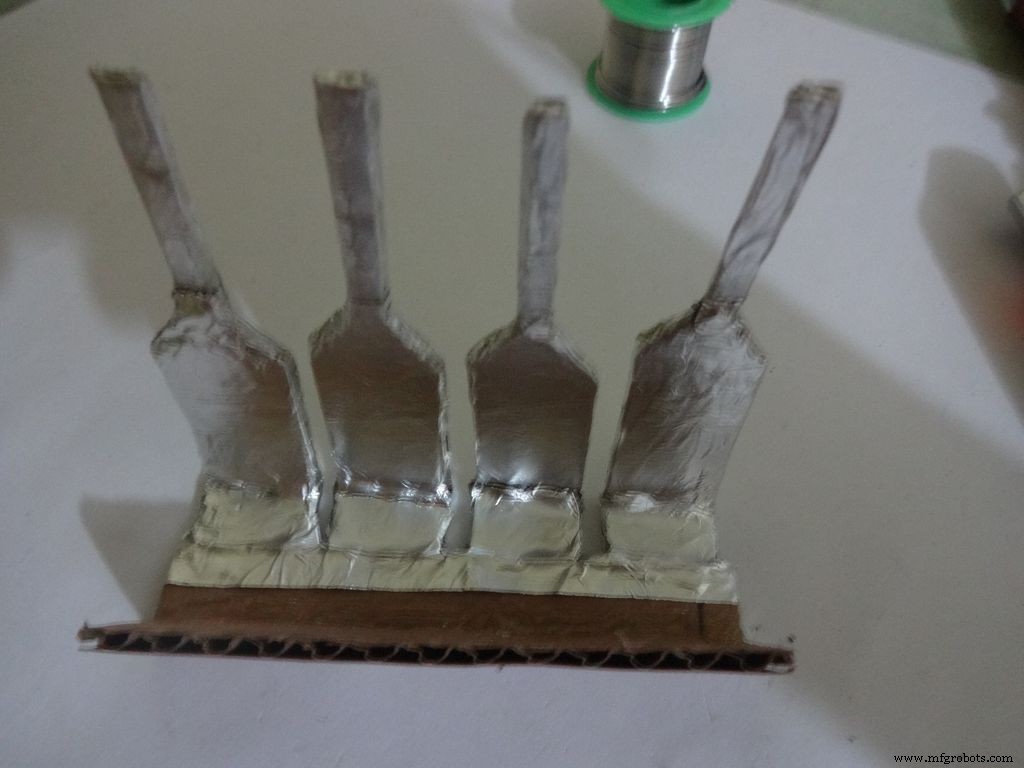
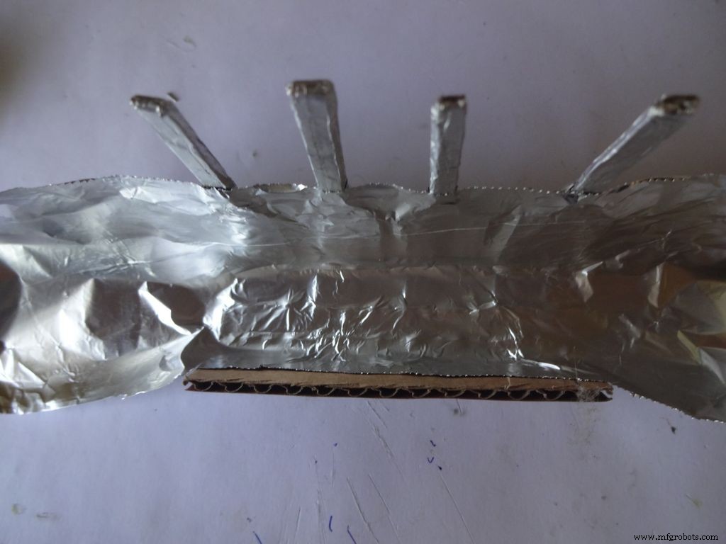
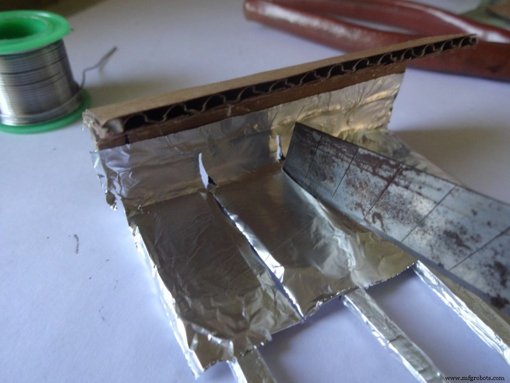
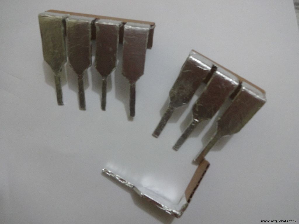

Cut a piece of foil 1x2inches and stick it carefully, fold by fold to the leg ends with some metal-cardboard sticking glue. I used Fevibond.
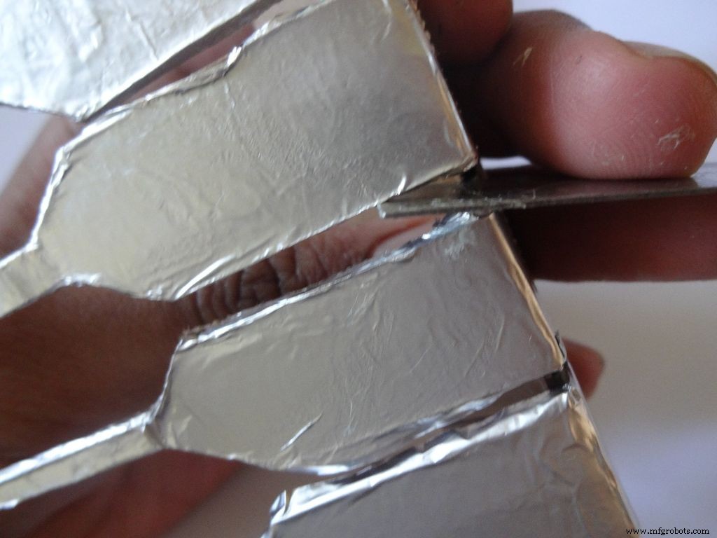
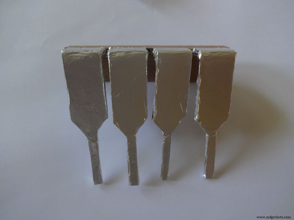
Next stick a patch that covers all the leg tops(as shown), make cuts slowly with a cutter. Do this carefully. The foil tends to tear to the sides. Use something flat to stick the foil in between the legs and give it a good finish.
Now cover it with transparent cello tape, just like you applied the foil, to protect it from sharp objects.
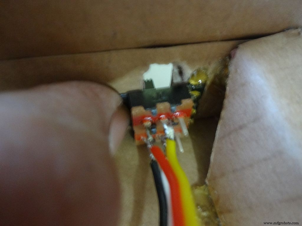
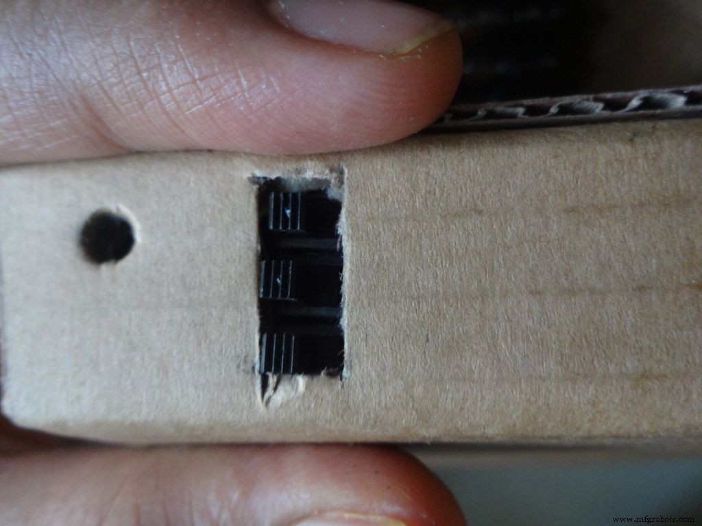
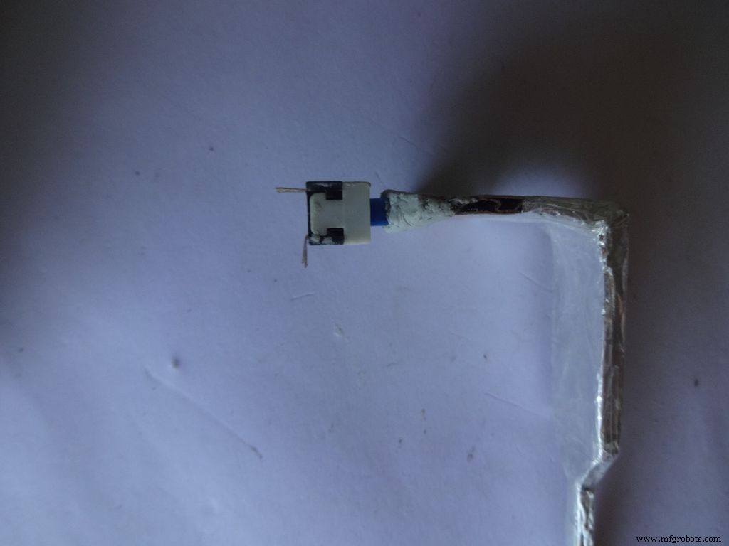
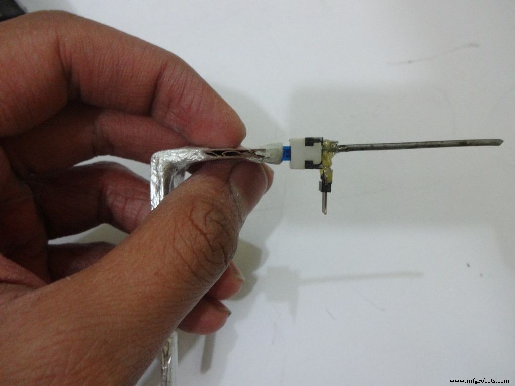
Step 25:The Power Switch
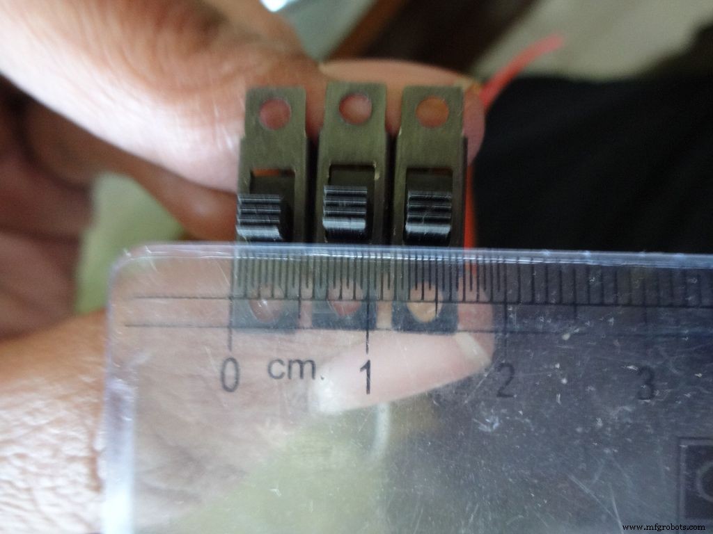
Measure and cut the power switch leg by properly keeping it in place. Temporarily stick the other pins with tape to get the pin1 position right.
Mix the m-seal(epoxy putty sealant, gets very hard when it dries) well. Put it as shown in the images and use powder+flat surface to shape it. Let it dry.
Also fill any gaps left in your case.
Note:We cant use hot glue here as it is rubbery and the switch needs to be stuck with some strong brittle material.
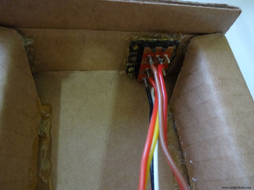
Step 26:Power switch to PCB

After The m-seal dries, place it in to check if everythings alright.
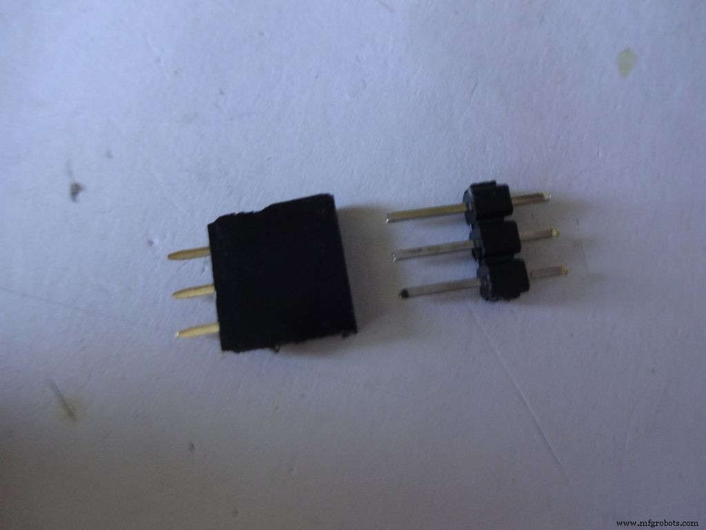
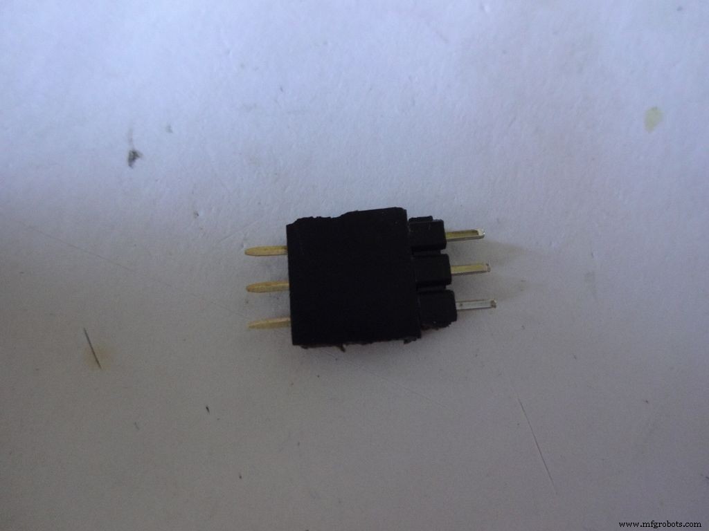
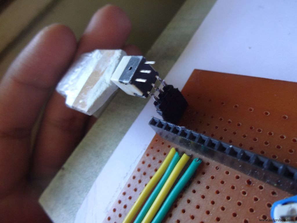
Cut 3pins of female and male headers place it on the PCB such that it aligns with the switch pins. Solder the female part.
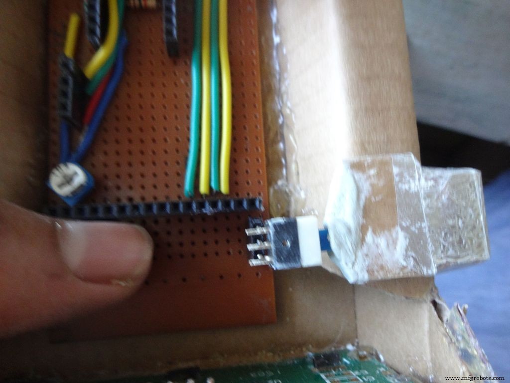
Tin the switch leads and the male header pins, join them. See if it fits at the right place.
Try pushing the switch on and off after placing a finger behind the switch for support. We will add a support rod later on.
Connect a side pin of female header(power switch) to Vin. I realised this late and had to undergo lots of trouble.
Secure the header Pin with hot glue.
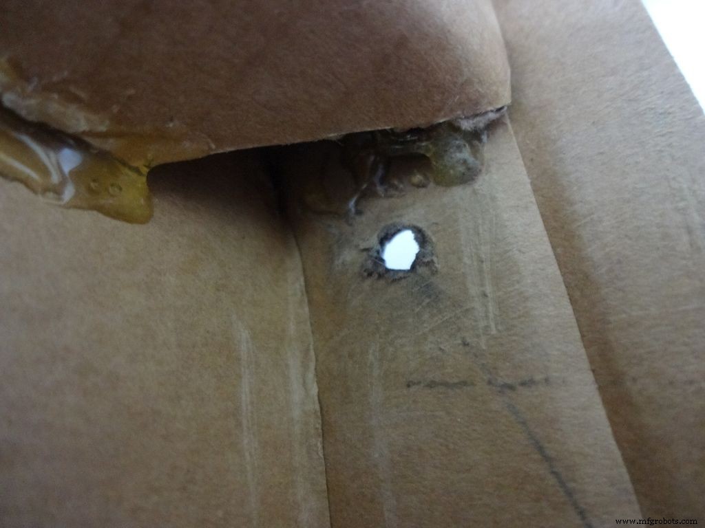
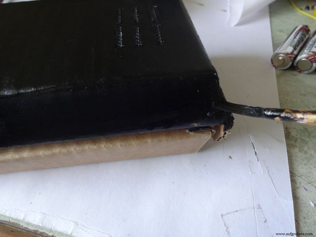
Step 27:Making the USB Port

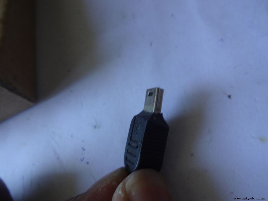
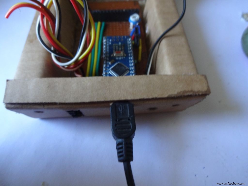
Put the PCB properly in (with Arduino) and cut a rectangle for the mini USB port.
Remove some plastic from the USB cable so that it fits the Arduino properly. Test whether connection is proper.
Step 28:Some other things...

I removed all the LEDs from the Arduino Nano and also the power LED on my RTC module. These consume unnecessary power, which matters if you are operating on a battery.
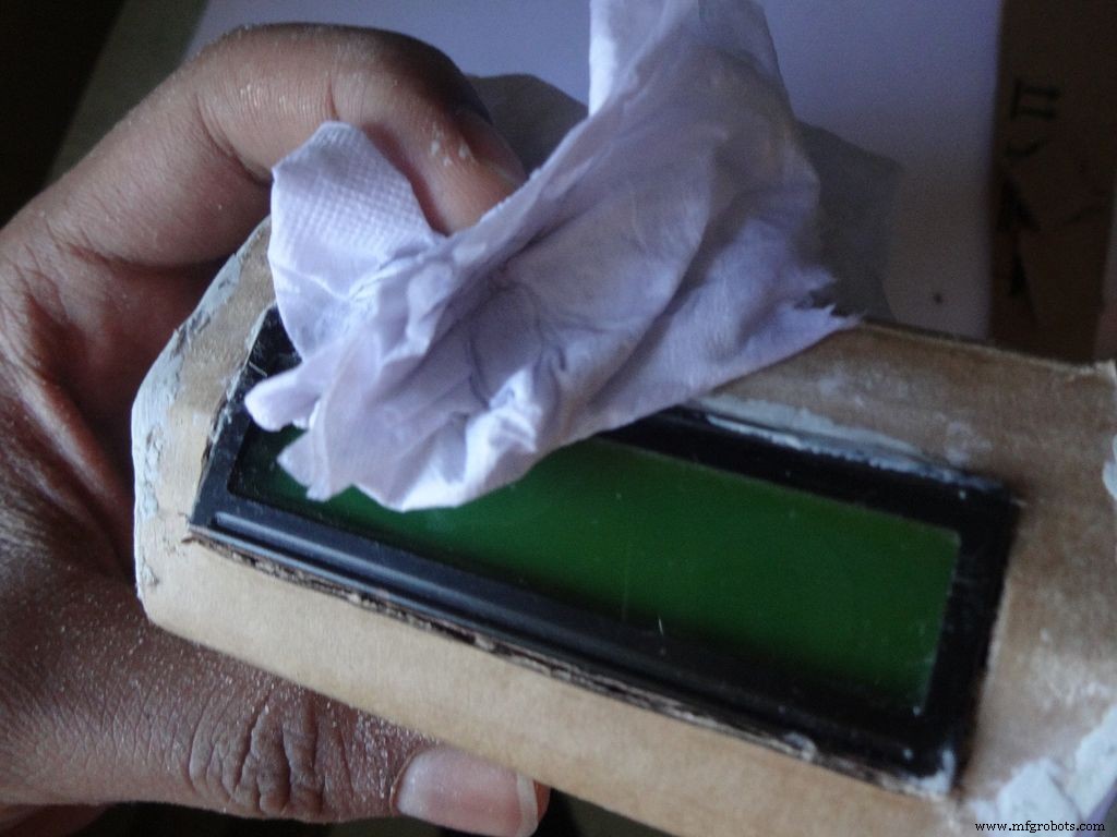
Sand the dried m-seal so that it mixes smoothly with the cardboard. Clean the powder with a wet paper napkin before painting.
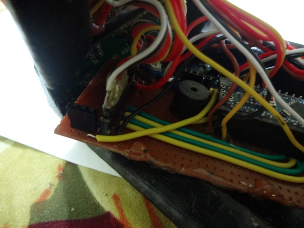
I also added a buzzer which may be used for some functions. Buzzers are sensitive, don't use too much heat while soldering!
Step 29:Time to paint!
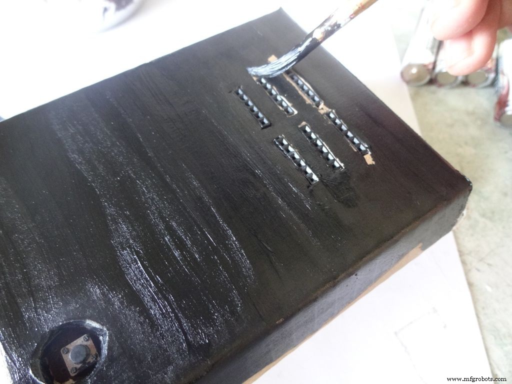
Dont use direct thick paint while painting, this cases brush patterns to appear. Use sufficient water.
Make sure no tiny bubbles are formed. These form when you dab the brush too much.
Dont paint the cover hinge, the paint will restrict it.
This is just a base coat. Another layer of paint will be added while finishing up.
Step 30:Soldering all the wires
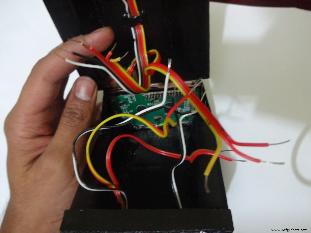
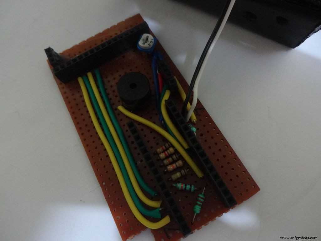
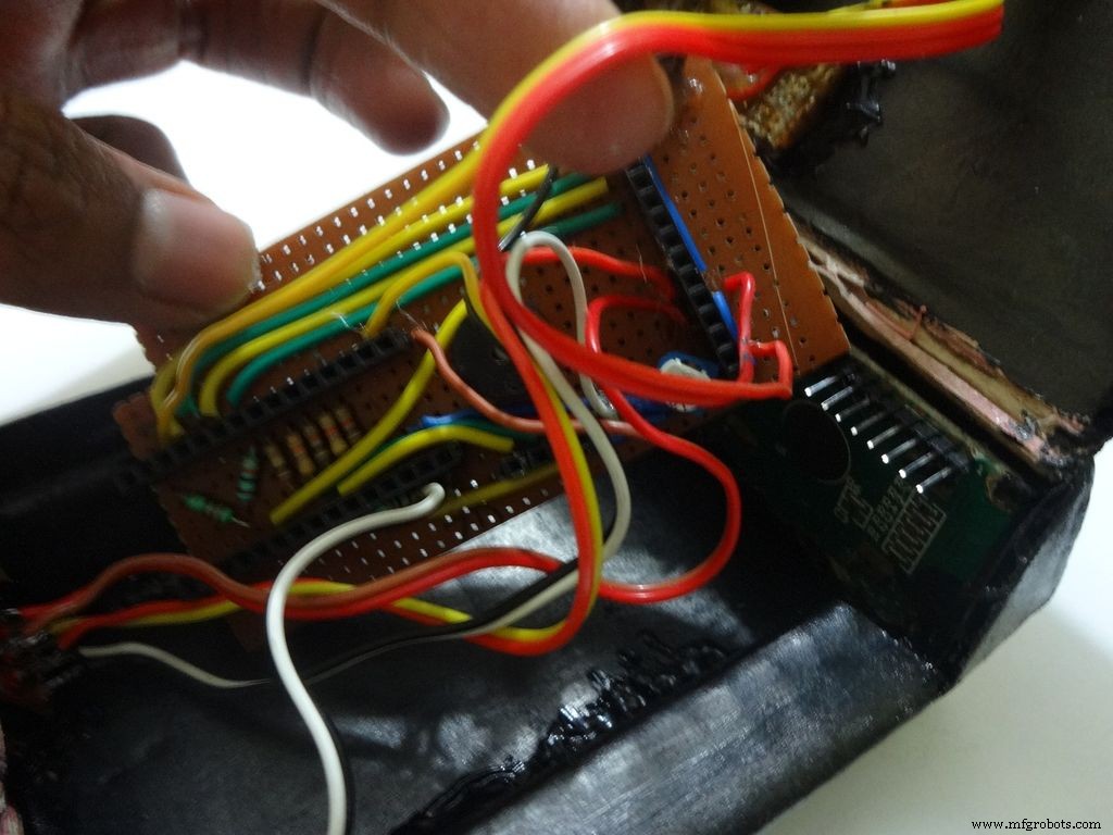
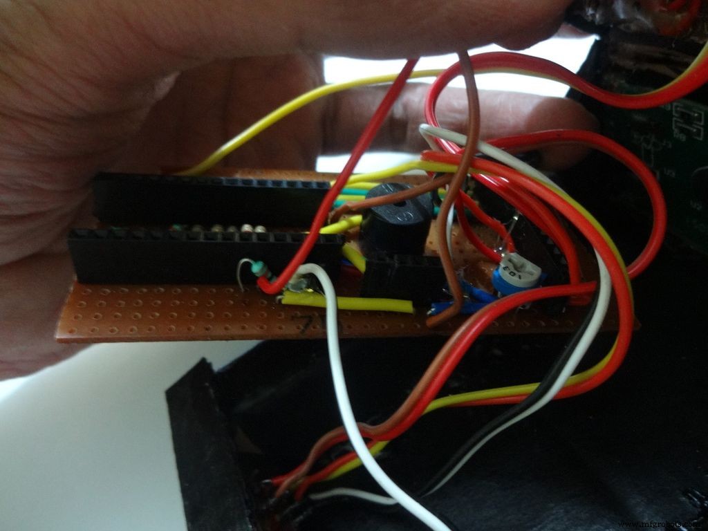
Make sure you refer the circuit design before making any connections.
First connect the reset switch, one end to RST and one end to GND.
Then, the backlight switch. One end to +5V and other end to 'A' or Anode of the backlight LED. Also connect 'K', Cathode to GND.
Next is the RS switch, connect one end to RS and other to pin D1(TX).
And finally the Enable switch. Connect one end to 'E' or Enable and other end to pin D0(RX).
Switches
Where to?
Reset - pushbutton RST and GND Backlight - slide +5V and A RS - slide D1 (TX) and RS Enable - slide D0 (RX) and E
Note:Pins D0 and D1 are connected through switches as keeping them connected sometimes causes problems while using Serial(for debugging).
This completes the base wiring. Apply hot glue after double checking the connections.
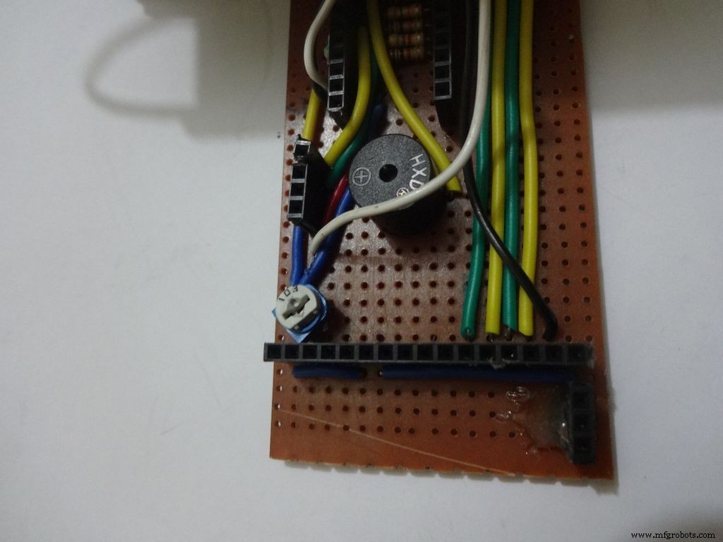
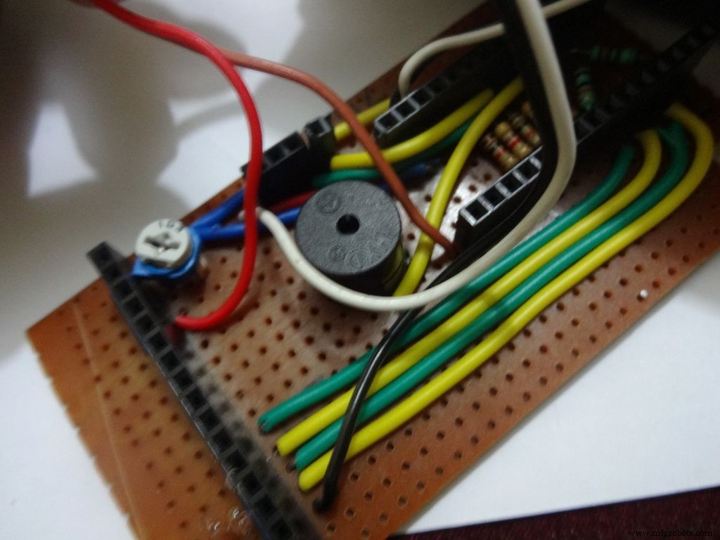
Then connect the 3 wires of mode change button:The 10k pulldown resistor to GND. 220 Ohm resistor to pin D11 and input pin to +5V or VCC
Finally connect the 6 wires from the test slots to their appropriate places(shown in images).
Positive
Negative
Resistance Test A7 GND Capacitance Test A0 GND Diode Test A6 D12
Note:All the +5Vs and GNDs are same and hence connect to most convinient spot.
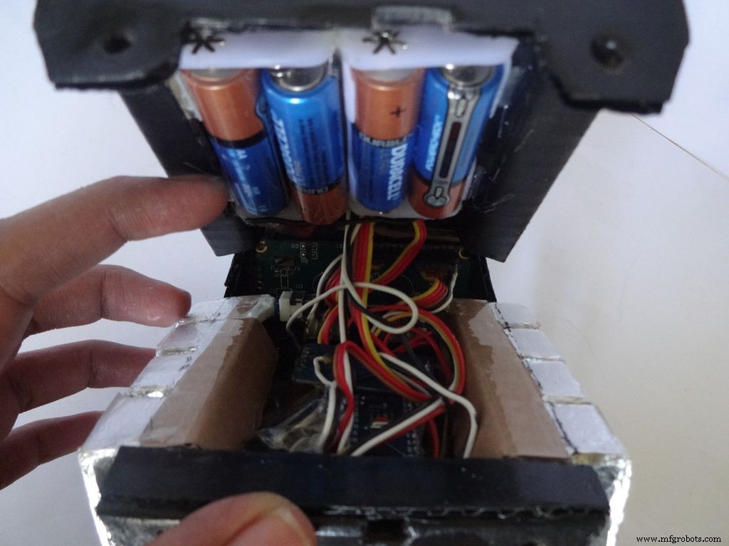
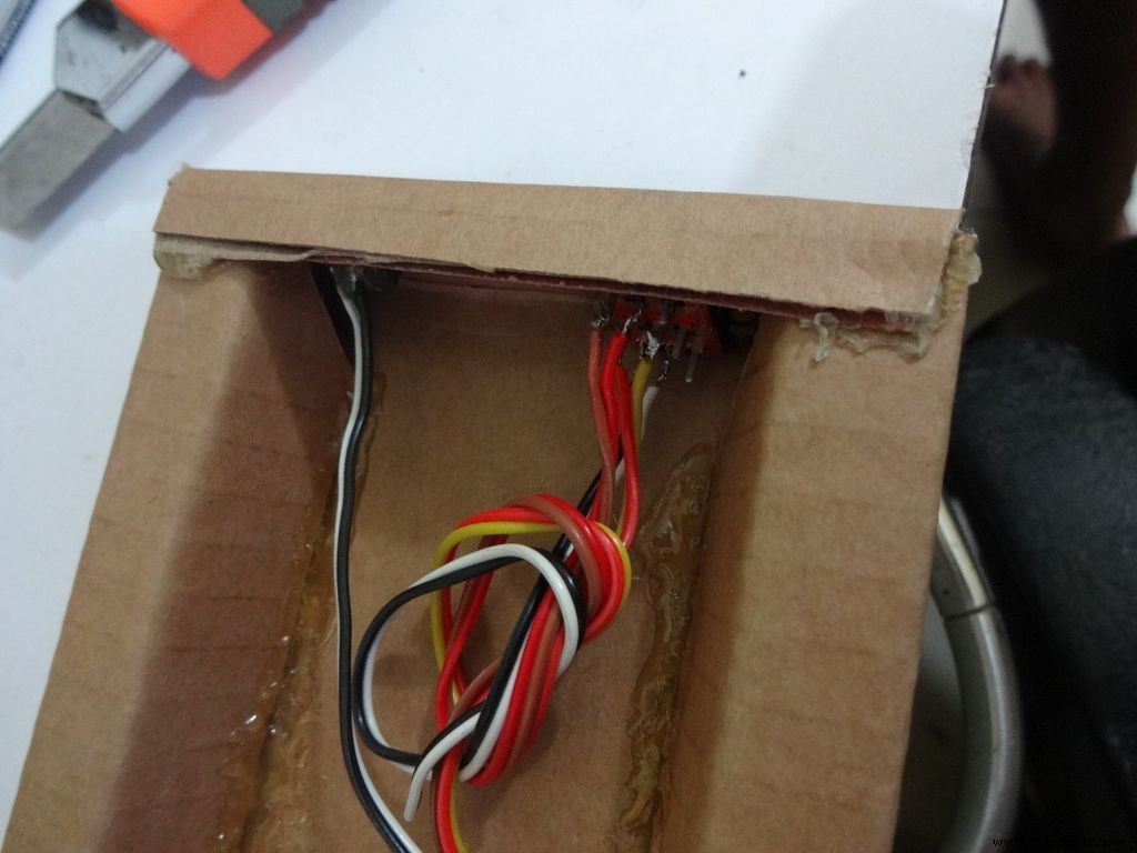
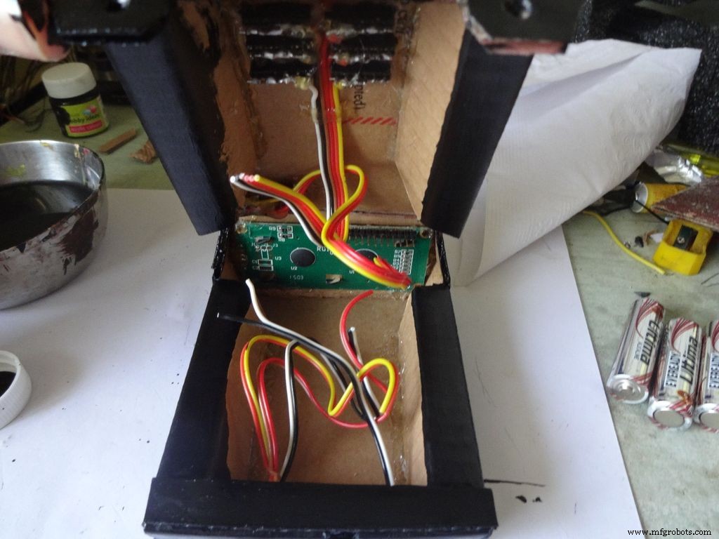
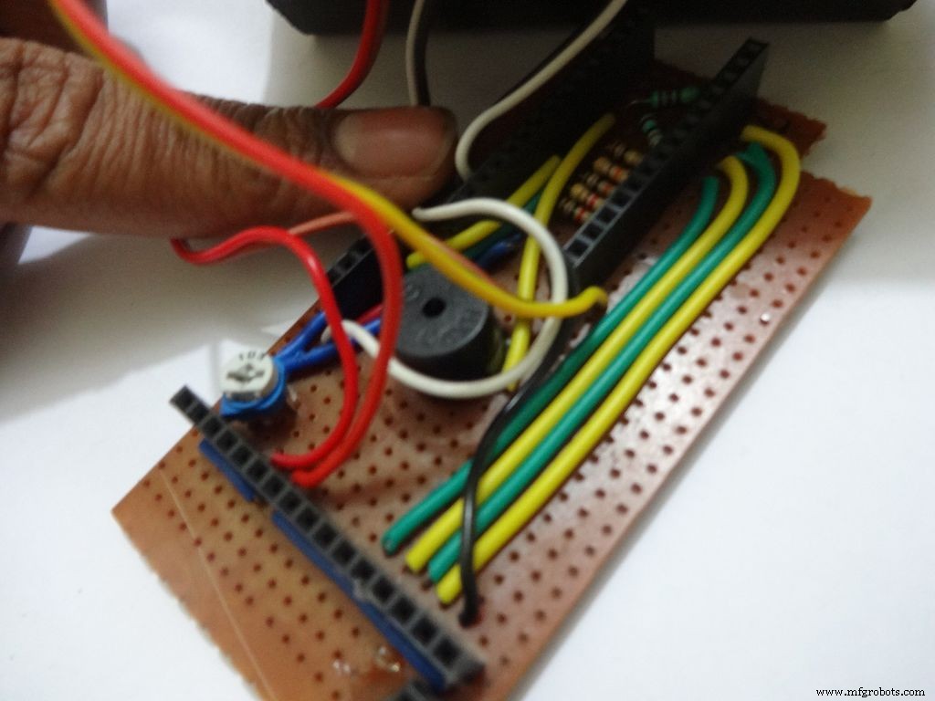
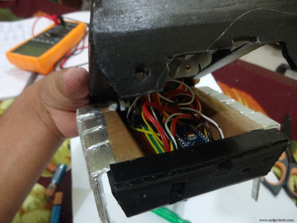
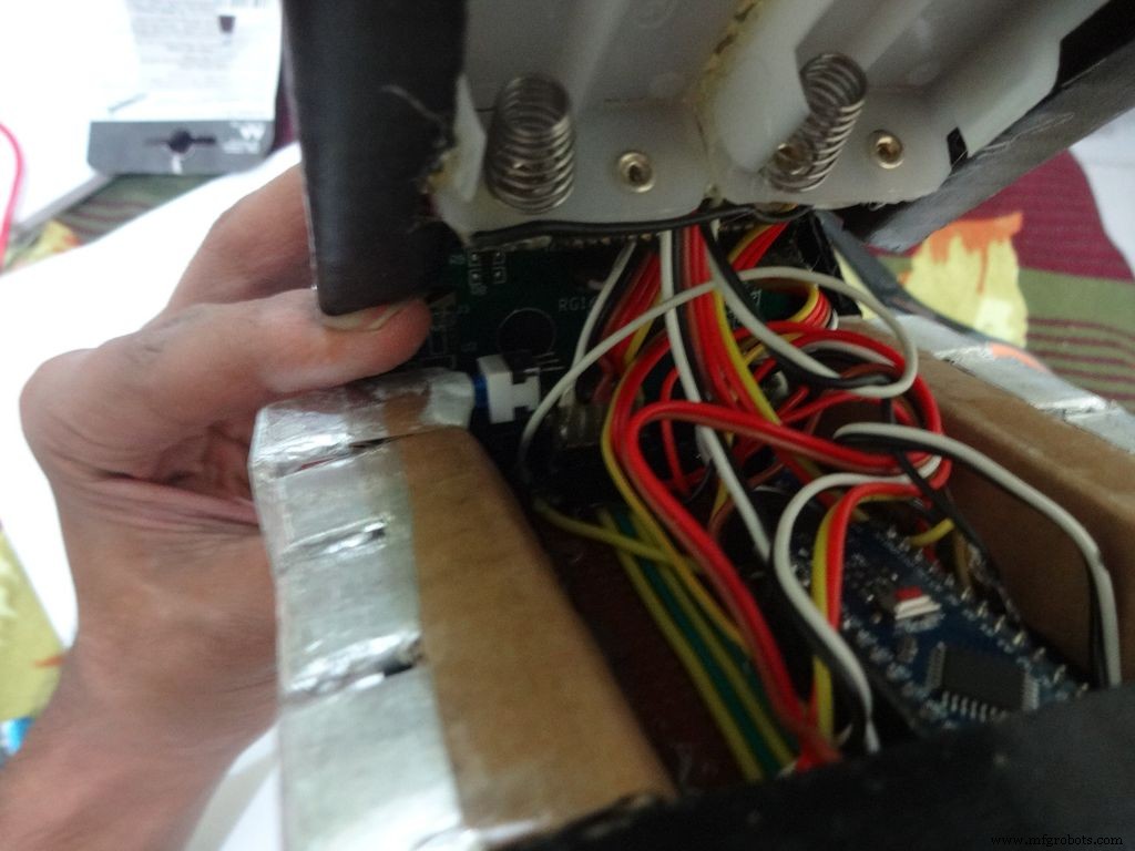
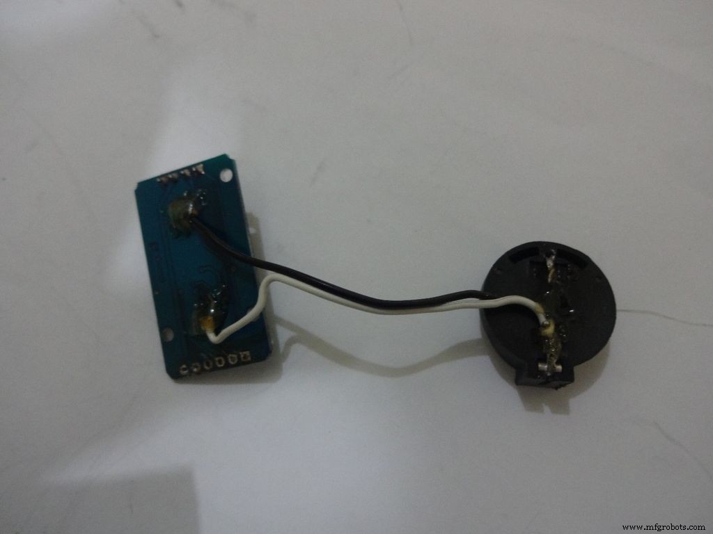
Step 31:Adding the battery case
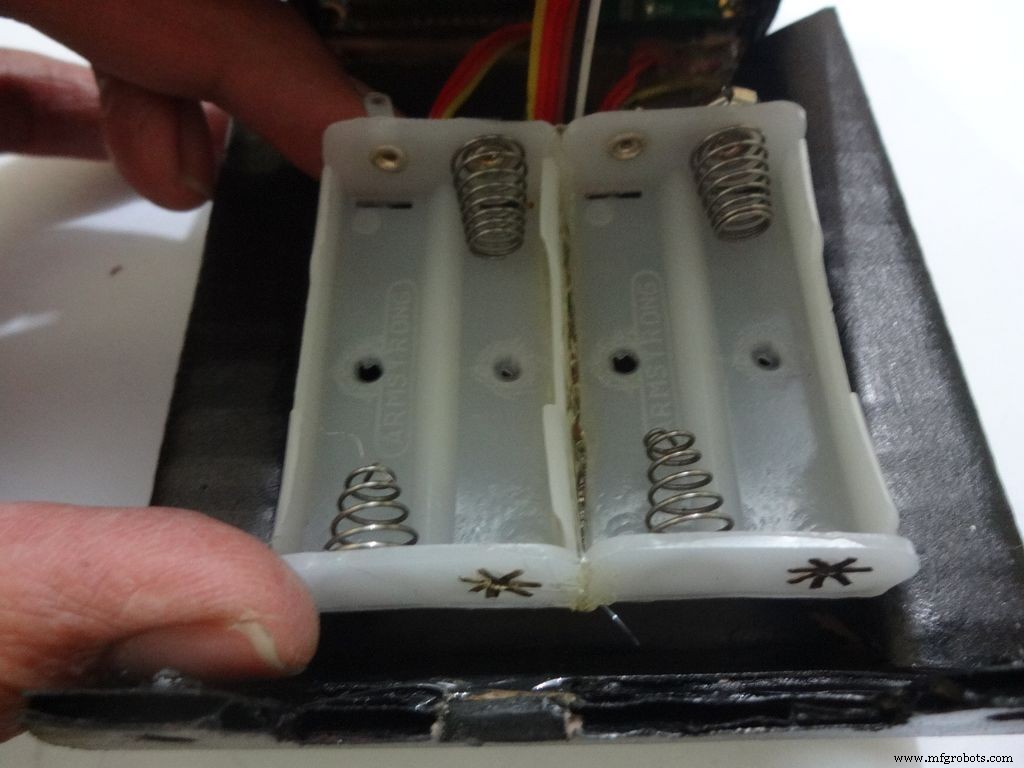
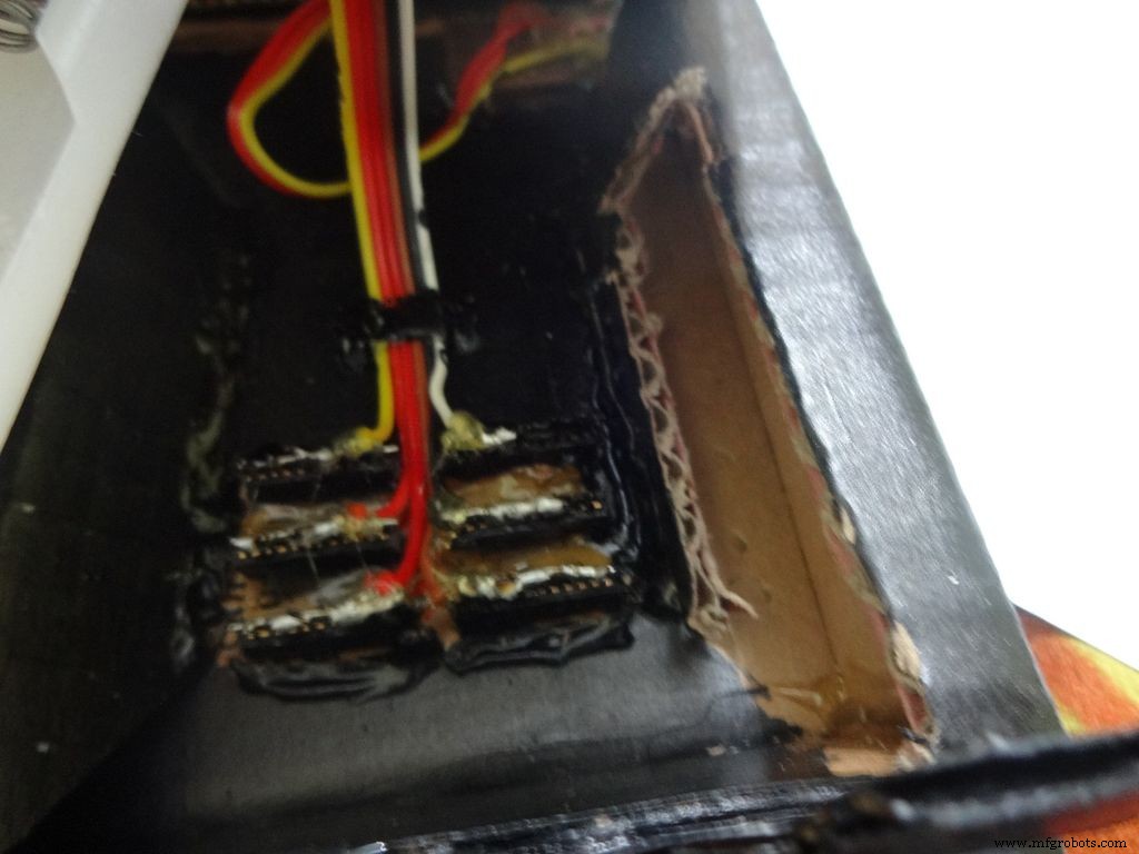
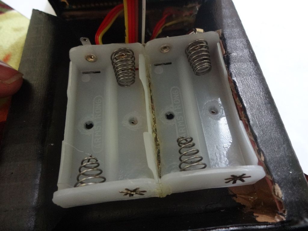

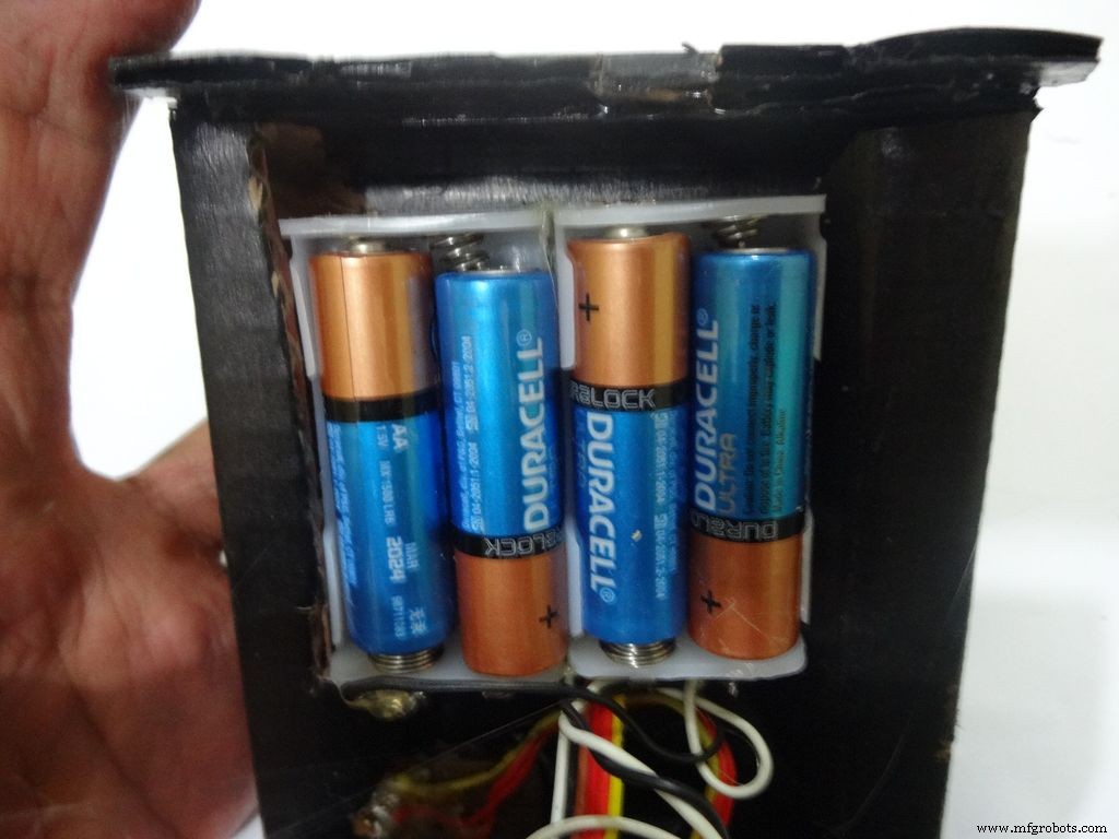
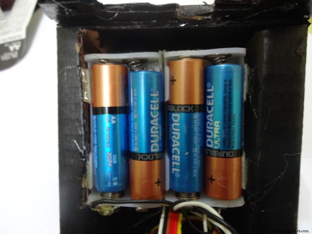
Place the battery case at the top cover, make cuts to place it inside such that the cover can be closed properly.
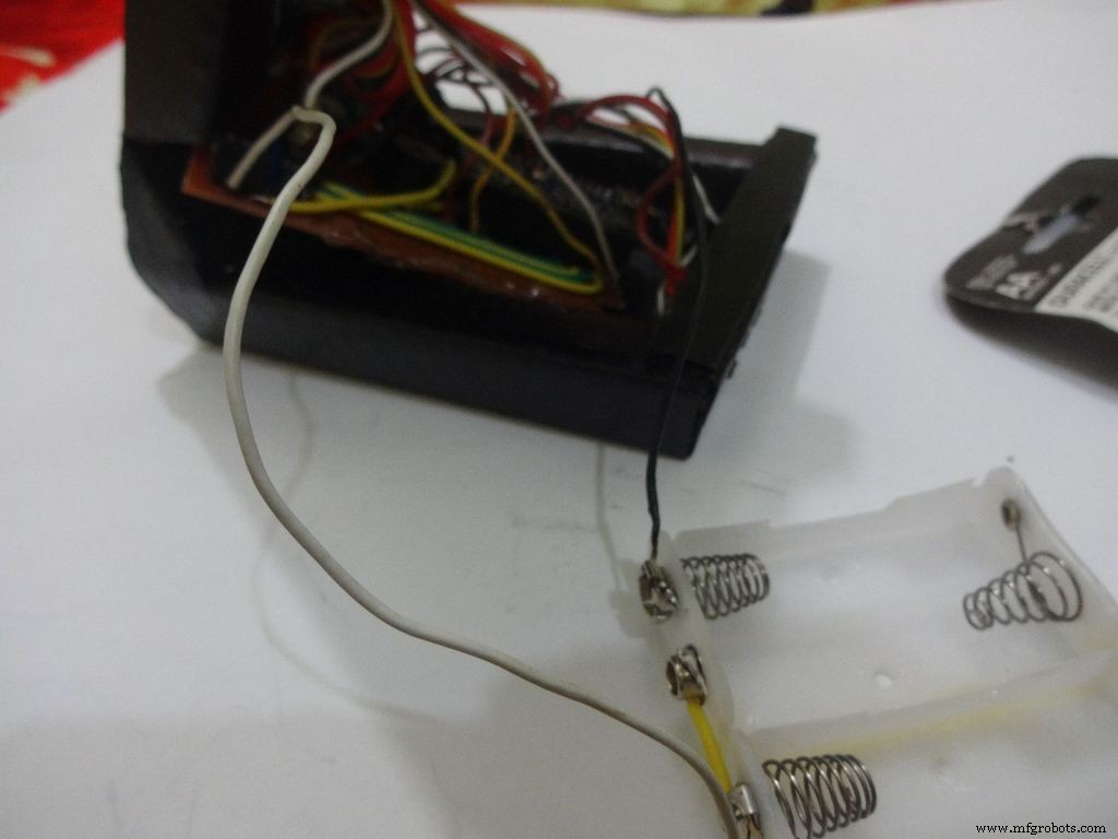
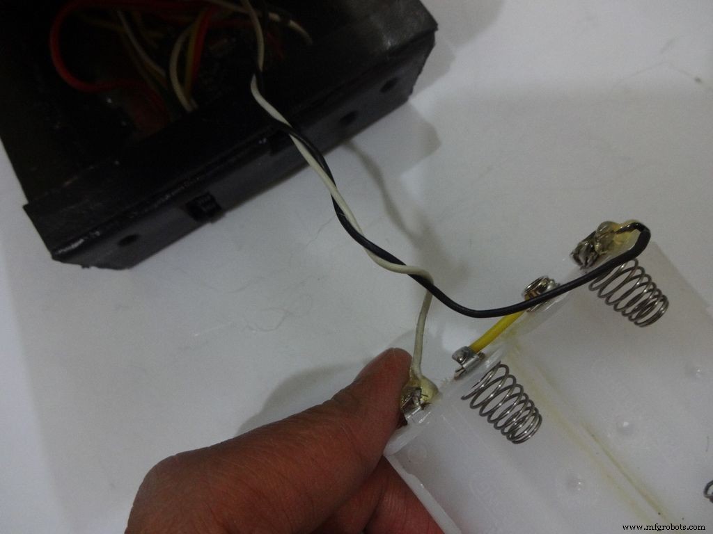
Solder Wires to the case, strip and tin them. Solder the positive end to the middle pin of power switch and negative end to ground.
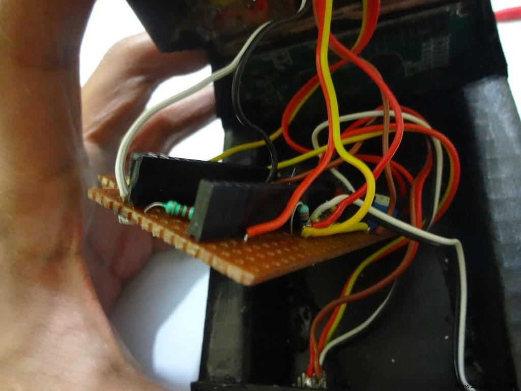
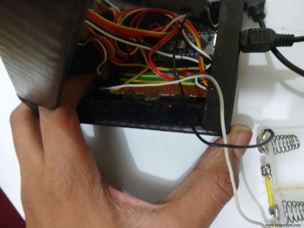
Glue the PCB to the base after making all the connections.
Twist the wires and place them in position. Insert batteries(the case expands a bit on inserting batteries) and glue the case to the cover.
Step 32:Adding the Legs
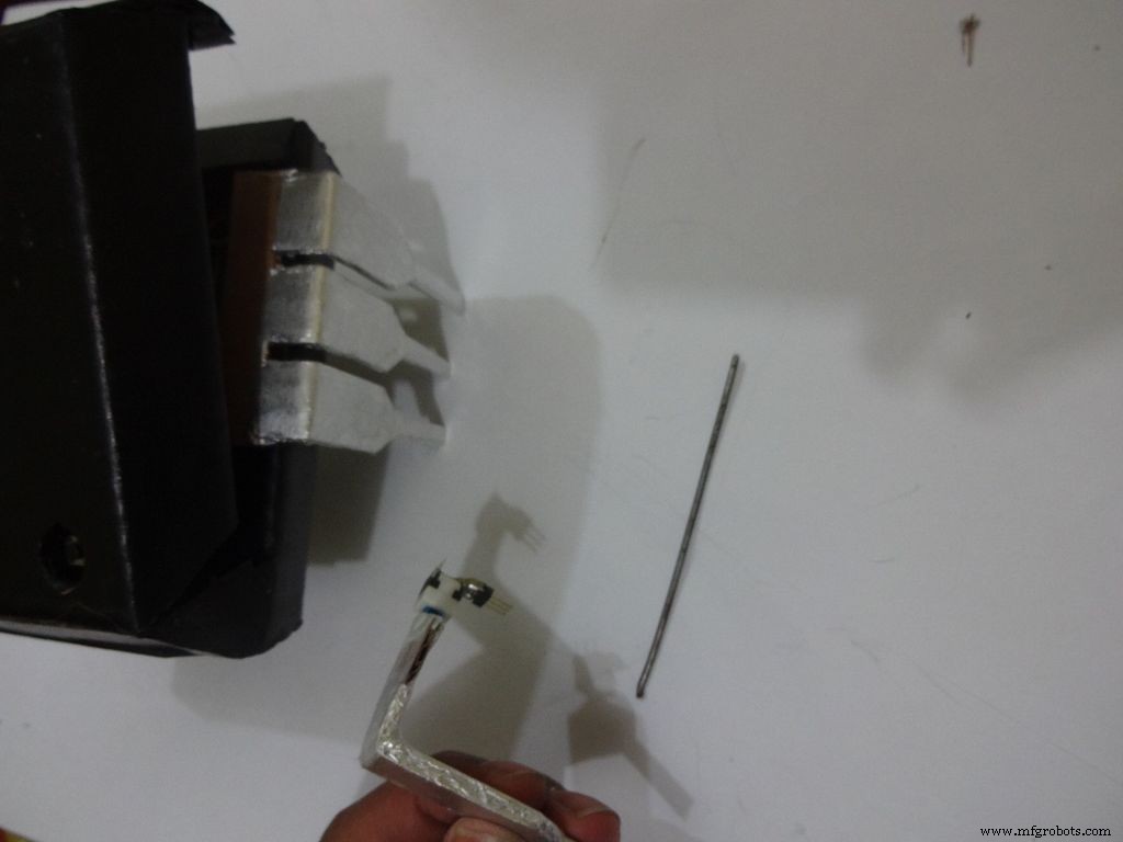
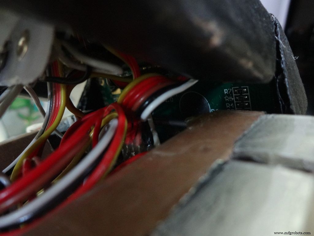
Cut the inner part of legs so that it fits in properly. Stick it it place.
Put the power switch pin in to check if it fits in perfectly. Remove it, add a metal rod, piece of wood or anything strong of proper length that will prevent the switch from moving back. Glue it in place.
Check the switch, it should be turning on/off smoothly.
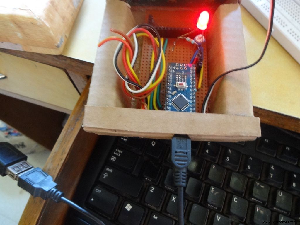
Switch on the IC and test all the functions. If its not working skip to the troubleshooting section.
Step 33:Finishing up!
Use M-seal (or equivalent) to fill any small gaps around the testing area and the mode change button. After drying, sand it well and apply a second layer of paint.
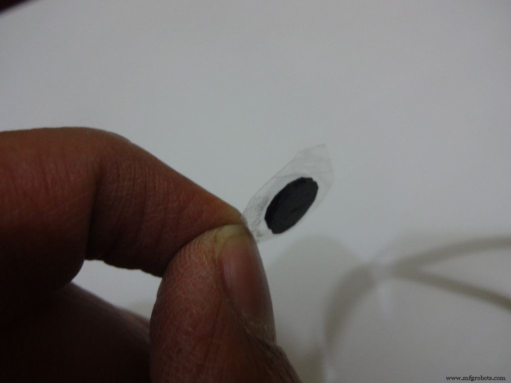
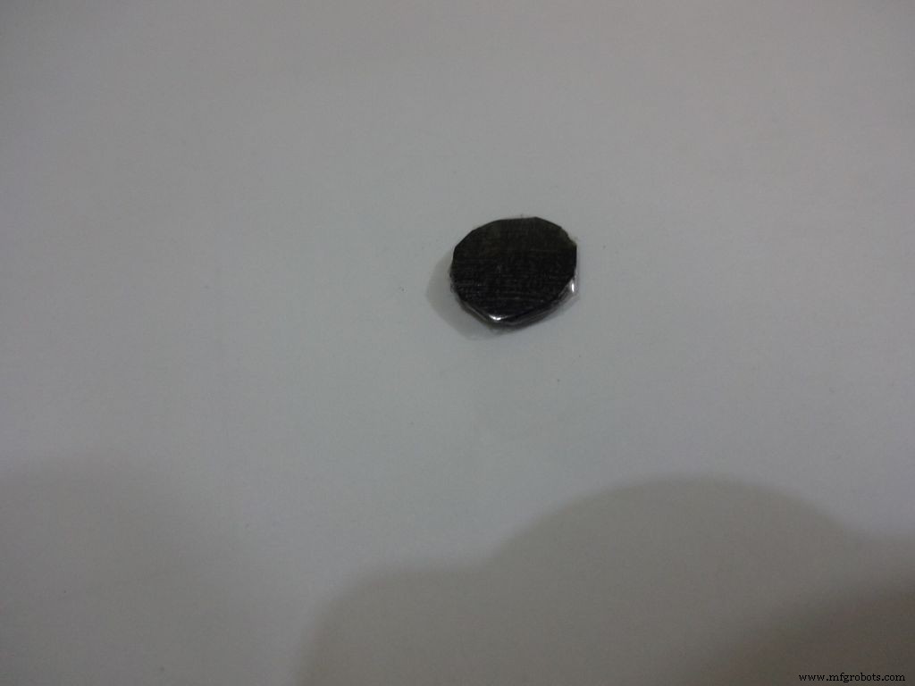
Make the button with a small piece of cardboard, paint it black and cover it with tape(gives a shiny finish). Apply a tiny drop of glue and stick the button in place.
Step 34:Problems and Troubleshooting

Do everything correctly. This is the most boring most of any project and you dont wanna get here just because you soldered the wrong pins!
<울>
Step 35:Things I did, some mistakes I made
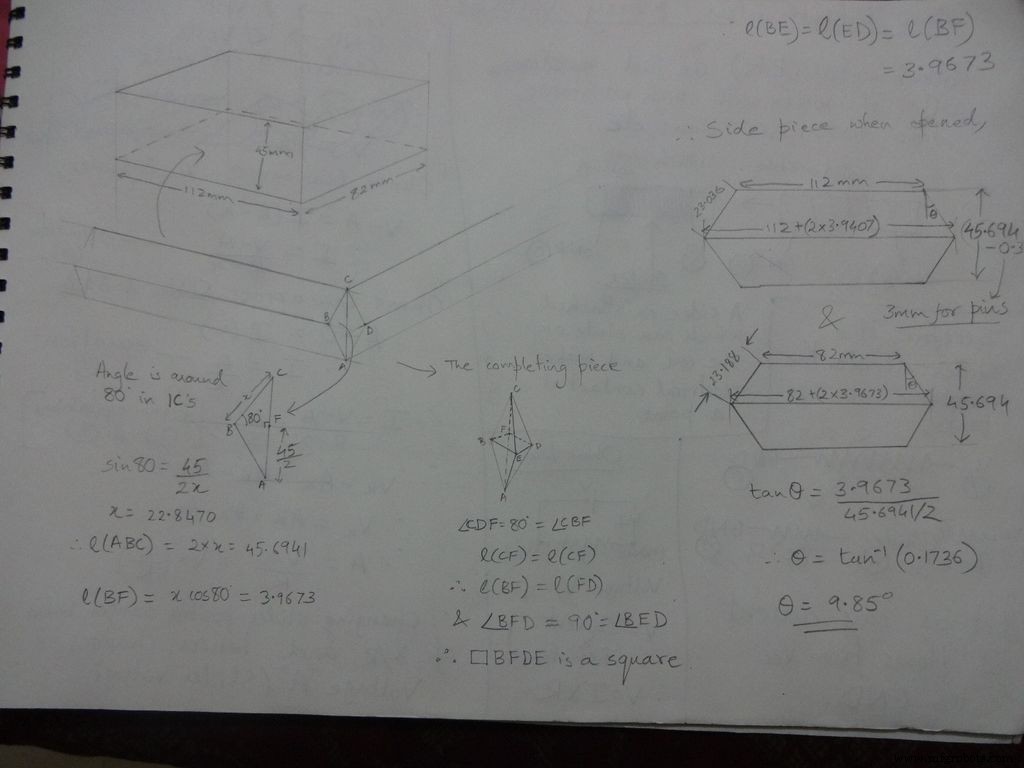

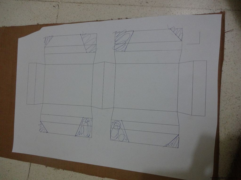
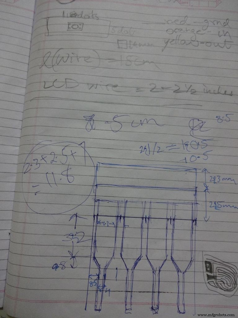
While testing the various circuits and when I had the rough idea of what I want to make, I decided to go with the IC design. I measured actual ICs, took ratios of their lengths, got the angle with some trignometry to be around 80 degrees. Then I decided the inner box length and breadth and built upon it(shown in image). Once the layout was planned, I initially started to draw it accurately on a large size paper. After a bit of a struggle of drawing accurate lines, I realised that this kind of work should be done on a computer! So I learnt CAD basics and succesfully made the layout on it. :) But this layout didnt work out and I had to redo the entire cutting and making of the case.(See images)
While removing the LEDs on the Arduino Nano I used excess pressure to remove a stubborn LED, and ended up removing a PCB pad. Always desolder without forcing/applying pressure on the joints, the pads are delicate and easily come off if you dont stay calm.
When all the solder joints were made and project was about to get finished, in excitement and eagerness, I glued the PCB inside the case before adding the battery case. Had to re-melt the hot glue with a soldering iron (carefully not to melt any wire insulation) and remove the PCB out to solder the battery case wires in. The soldering iron can be cleaned afterwards.
The RTC module battery was coming in way of the batteries while closing and so I separated the battery holder(Warning:desolder only with the battery removed) and added extension wires so that the battery can be placed at the sides where there is space.
All the Layout PDFs, CAD Files and the Main code can be downloaded here:Google Drive
<섹션 클래스="섹션 컨테이너 섹션 축소 가능" id="코드">//Analog pin used to find resistanceint Apin=7;//values of r1 to r5float r1=1000;float r2=4700;float r3=10000;float r4=47000;float r5=100000;//pins of r1 to r5int r1_pin=2;int r2_pin=3;int r3_pin=4;int r4_pin=5;int r5_pin=6;float reading=0; //read from analog pin and store herefloat R=0; //calculate unknown and store hereString finalR; //final value to be displayed along with unitsint caseno; //for debugging, stores the case number // we divide the entire range into cases and assign each a number, // total 5 cases // case1 :less than 2850 // case2 :2850 to 7350 // case3 :7350 to 28500 // case4 :28500 to 73500 // case5 :more than 73500#include// needed for converting float to string, //has the String(float,n) function. Explained below.void setup() { Serial.begin(9600);}void loop() { //first we find unknown resistance using 1kOhm resistor //Therefore, disable R2, R3, R4 and R5 digitalWrite(r2_pin, LOW); //turn each pin to LOW before setting it as INPUT pinMode(r2_pin, INPUT); // turning it to INPUT when its HIGH enables the // internal pullup resistor digitalWrite(r3_pin, LOW); pinMode(r3_pin, INPUT); digitalWrite(r4_pin, LOW); pinMode(r4_pin, INPUT); digitalWrite(r5_pin, LOW); pinMode(r5_pin, INPUT); pinMode(r1_pin, OUTPUT); digitalWrite(r1_pin, HIGH); //read and calculate resistance reading=analogRead(Apin); R=(reading*r1)/(1023-reading); // if value <2850, finalR =value(using 1kOhm) if(R<2850){ caseno=1; if(R<1000){ //if value less than 1000 use "Ohm" not "kOhm" finalR =String(R,2) + "Ohm"; //String(float,n) Converting float to string //with n digits after decimal // attach "Ohm" after value to the string, //'+' joins two strings here } else{ //use "kOhm R=R/1000; finalR =String(R,2) + "kOhm"; } } //if value between 2850 and 7350 , use value obtained by 4.7kOhm else if(R>=2850 &&R<7350){ caseno=2; digitalWrite(r1_pin, LOW); //Enable only 4.7kOhm pinMode(r1_pin, INPUT); digitalWrite(r3_pin, LOW); pinMode(r3_pin, INPUT); digitalWrite(r4_pin, LOW); pinMode(r4_pin, INPUT); digitalWrite(r5_pin, LOW); pinMode(r5_pin, INPUT); pinMode(r2_pin, OUTPUT); digitalWrite(r2_pin, HIGH); reading=analogRead(Apin); R=(reading*r2)/(1023-reading)/1000; finalR =String(R,2) + "kOhm"; } //if value between 7350 and 28500, use value obtained by 10kOhm else if(R>=7350 &&R<28500){ caseno=3; digitalWrite(r1_pin, LOW); pinMode(r1_pin, INPUT); digitalWrite(r2_pin, LOW); pinMode(r2_pin, INPUT); digitalWrite(r4_pin, LOW); pinMode(r4_pin, INPUT); digitalWrite(r5_pin, LOW); pinMode(r5 _pin, INPUT); pinMode(r3_pin, OUTPUT); digitalWrite(r3_pin, HIGH); reading=analogRead(Apin); R=(reading*r3)/(1023-reading)/1000; finalR=String(R,2) + "kOhm"; } //if value between 28500 and 73500, use value obtained by 47kOhm else if(R>=28500 &&R<73500){ caseno=4; digitalWrite(r1_pin, LOW); pinMode(r1_pin, INPUT); digitalWrite(r2_pin, LOW); pinMode(r2_pin, INPUT); digitalWrite(r3_pin, LOW); pinMode(r3_pin, INPUT); digitalWrite(r5_pin, LOW); pinMode(r5_pin, INPUT); pinMode(r4_pin, OUTPUT); digitalWrite(r4_pin, HIGH); reading=analogRead(Apin); R=(reading*r4)/(1023-reading)/1000; finalR =String(R,2) + "kOhm"; } //if value more than 73500, use value obtained by 100kOhm else if(R>=73500){ caseno=5; digitalWrite(r1_pin, LOW); pinMode(r1_pin, INPUT); digitalWrite(r2_pin, LOW); pinMode(r2_pin, INPUT); digitalWrite(r3_pin, LOW); pinMode(r3_pin, INPUT); digitalWrite(r4_pin, LOW); pinMode(r4_pin, INPUT); pinMode(r5_pin, OUTPUT); digitalWrite(r5_pin, HIGH); reading=analogRead(Apin); R=(reading*r5)/(1023-reading)/1000; finalR =String(R,2) + "kOhm"; } Serial.println(finalR); //printing the final string with units Serial.println(" "); 지연(1000); }
/* RCTiming_capacitance_meter * code concept taken from Paul Badger 2008 * * The capacitor's voltage at one time constant is defined as * 63.2% of the charging voltage. * i.e, A Capacitor is filled to 63.2% of its total capacity in * 1 Time Constant */ int analogPin=0; // analog pin for measuring capacitor voltage int chargePin=7; // pin to charge the capacitor - connected to // one end of the charging resistor int dischargePin=12; // pin to discharge the capacitor, // same used for diode test(checkPin1) float resistorValue=10000.0; // We use 10kOhm resistor unsigned long startTime; unsigned long elapsedTime; float microFarads; // floating point variable to preserve precision float nanoFarads;void setup(){ pinMode(chargePin, OUTPUT); // set chargePin to output digitalWrite(chargePin, LOW); Serial.begin(9600); // initialize serial transmission for debugging}void loop(){ digitalWrite(chargePin, HIGH); // set chargePin HIGH and capacitor charging startTime =millis(); while(analogRead(analogPin) <648){ // just wait and do nothing till 648 // 647 is 63.2% of 1023, // which corresponds to full-scale voltage } elapsedTime=millis() - startTime; // convert milliseconds to seconds ( 10^-3 ) // and Farads to microFarads ( 10^6 ), net 10^3 (1000) microFarads =((float)elapsedTime / resistorValue) * 1000; // (float) converts "unsigned long" elapsed time to float Serial.print(elapsedTime); // print the value to serial port Serial.print(" mS "); // print units if (microFarads> 1){ Serial.print((long)microFarads); // print the value to serial port Serial.println(" microFarads"); // print units } else { // if value is smaller than one microFarad, convert to nanoFarads (10^-9 Farad). nanoFarads =microFarads * 1000.0; // multiply by 1000 to convert to nanoFarads (10^-9 Farads) Serial.print((long)nanoFarads); // print the value to serial port Serial.println(" nanoFarads"); // print units } /* dicharge the capacitor */ digitalWrite(chargePin, LOW); // set charge pin to LOW pinMode(dischargePin, OUTPUT); // set discharge pin to output digitalWrite(dischargePin, LOW); // set discharge pin LOW while(analogRead(analogPin)> 0){ // wait until capacitor is completely discharged } pinMode(dischargePin, INPUT); // set discharge pin back to input} String state ="null"; //prints "null" for reverse bias or nothing connectedint checkPin1 =12;int checkPin2 =6;void setup() { Serial.begin(9600);}void loop() {pinMode(checkPin1, OUTPUT); digitalWrite(checkPin1, LOW); //pin 11 is set to low//analog read is normally pulled up by the 10k resistor, so null reading is 1023//In forward bias, the analog pin gets connected to checkPin1, which is LOW. So reading less than 1023//Practically a small current flows in reverse bias as well, so we take 700 to differentiate if(analogRead(checkPin2)<700){ state="forward"; } Serial.println(state); Serial.println(analogRead(checkPin2)); state ="null"; 지연(500);} // Date and time functions using a DS1307 RTC connected via I2C and Wire lib#include #include RTC_DS1307 rtc;//creating "rtc" object of RTC_DS1307, objects are used to access functions //more on objects and classes:https://www.youtube.com/watch?v=ABRP_5RYhqUchar daysOfTheWeek[7][12] ={"Sunday", "Monday", "Tuesday", "Wednesday", "Thursday", "Friday", "Saturday"};void setup () { Serial.begin(9600); rtc.begin(); // following line sets the RTC to the date &time this sketch was compiled // rtc.adjust(DateTime(F(__DATE__), F(__TIME__))); // This line sets the RTC with an explicit date &time, for example to set // January 21, 2014 at 3am you would call:// rtc.adjust(DateTime(2014, 1, 21, 3, 0, 0));}void loop () { DateTime now =rtc.now(); Serial.print(now.year()); Serial.print('/'); Serial.print(now.month()); Serial.print('/'); Serial.print(now.day()); Serial.print(" ("); Serial.print(daysOfTheWeek[now.dayOfTheWeek()]); Serial.print(") "); Serial.print(now.hour()); Serial.print(':'); Serial.print(now.minute()); Serial.print(':'); Serial.print(now.second()); 직렬.println(); 직렬.println(); 지연(1000);} 제조공정
구성품 및 소모품 Arduino UNO × 1 Adafruit Standard LCD - 파란색 바탕에 16x2 흰색 × 1 SparkFun 푸시버튼 스위치 12mm × 1 Perma-Proto 브레드보드 절반 크기 × 1 점퍼 와이어(일반) × 1 저항 1k 옴 × 1 저항 10k 옴 × 1 저항 470k ohm 1% × 3 저항 680옴 1% × 3
용어 또는 전문 용어를 혼동하는 것은 전자 제품, 특히 트랜지스터와 저항에 대해 이야기할 때 일반적입니다. 그러나 문제는 이름을 어떻게 선택했는지에만 있는 것이 아닙니다. 초보자를 혼란스럽게 할 수 있는 기능입니다. 당사 웹 사이트에는 모든 PCB 구성 요소에 대한 포괄적인 목록이 있습니다. 그러나 혼란을 없애기 위해 이러한 트랜지스터와 저항의 차이점에 대해 자세히 설명해야 할 때라고 생각했습니다. 이 가이드를 마치면 다음 전자 프로젝트에서 이러한 구성 요소를 사용하는 방법과 함께 이러한 구성 요소의 기능을 완전히 이해하게 될