

제조공정

산업 제조
폐열 회수 기술
폐열은 공정을 떠나 대기로 들어가는 공기, 배기 가스 및/또는 공정 제품의 폐수와 관련된 에너지입니다. 다양한 과정에서 발생되어 실용화되지 않고 대기 중으로 손실되거나 낭비되는 에너지입니다. 경제적인 방식으로 유용한 목적을 위해 에너지의 일부를 회수할 수 있을 만큼 충분히 높은 온도에서 공정에서 거부되는 에너지입니다.
폐열의 정의에서 열을 운반하는 폐수 흐름은 결국 대기 또는 지하수와 혼합되고 이러한 흐름에 포함된 에너지는 유용한 에너지로 사용할 수 없게 됩니다. 환경에 의한 폐기물 에너지의 흡수는 흔히 열 오염이라고 합니다.
폐열 회수는 다양한 WHR(폐열 회수) 기술을 통해 수행되어 귀중한 에너지원을 제공하고 전체 에너지 소비를 줄일 수 있습니다. 폐열을 포착하고 회수하는 데 사용할 수 있는 몇 가지 WHR 기술이 있습니다.
산업 공정에서 사용되는 상당한 양의 에너지는 배기 가스, 기류 및 공정을 떠나는 액체/고체 형태의 열로 낭비됩니다. 모든 폐열을 회수하는 것은 기술적으로나 경제적으로 불가능합니다. WHR 기술의 사용 증가는 온실 가스(GHG) 배출을 완화하는 역할도 합니다.
WHR 기술은 가스, 액체 또는 고체를 사용하는 프로세스에서 폐열을 포착하여 추가 에너지원으로 시스템으로 다시 전달하는 것으로 구성됩니다. 에너지원은 추가 열을 생성하거나 전기 및 기계적 전력을 생성하는 데 사용할 수 있습니다. 폐열은 어떤 온도에서도 거부될 수 있습니다. 일반적으로 폐열의 온도가 높을수록 폐열의 품질이 높아지고 WHR 프로세스의 최적화가 더 쉽습니다. 따라서 프로세스에서 가장 높은 잠재력의 최대 회수 가능한 열량을 발견하고 WHR 시스템에서 최대 효율 달성을 보장하는 것이 중요합니다.
폐열의 원인은 일반적으로 제품, 장비 및 공정에서 전도, 대류 및 복사를 통해 전달되는 열 손실과 연소 공정에서 방출되는 열을 포함합니다. 열 손실은 (i) 고온 열, (ii) 중온 열 및 (iii) 저온 열로 분류할 수 있습니다. WHR 기술은 폐열의 종류에 따라 최적의 WHR 효율을 달성할 수 있습니다.
고온 WHR은 400 ° C 이상의 온도에서 폐열을 회수하는 것으로 구성되며 중간 온도 폐열 범위는 100 ° C ~ 400 ° C, 저온 폐열 범위는 100 ° C 미만의 온도에 대한 것입니다. 일반적으로 대부분의 고온 범위의 폐열은 직접 연소 공정에서, 중온 범위는 연소 장치의 배기에서, 저온 범위는 공정 장치의 부품, 제품 및 장비에서 발생합니다.
폐열의 종류와 발생원에 따라 그리고 어떤 폐열 회수 시스템을 사용할 수 있는지를 정당화하기 위해서는 공정에서 회수할 수 있는 열의 양과 등급을 검토하는 것이 필수적입니다. 폐열의 정량화에 사용되는 세 가지 중요한 매개변수가 있습니다. 이러한 매개변수는 (i) 수량, (ii) 품질 및 (iii) 시간적 가용성입니다.
사용 가능한 폐열의 양 또는 양은 방정식 Q =V x d x Cp x (T1-T2)를 사용하여 계산할 수 있습니다. 여기서 Q는 열량, V는 열을 운반하는 물질의 유속, d는 물질의 밀도, Cp는 물질의 비열, (T1-T2)는 출구(T2)의 최종 최고 온도와 시스템 입구(T1)의 초기 온도. 사용 가능한 폐열의 양은 또한 폐기물 흐름의 엔탈피 흐름의 관점에서 표현될 수 있으며 방정식 H =m x h로 주어집니다. 여기서 H는 폐기물 흐름의 총 엔탈피 비율이고, m은 폐기물 흐름의 질량 유량이며 h는 폐기물 스트림의 특정 엔탈피입니다.
품질은 대략적으로 폐기물 흐름의 온도로 표현될 수 있습니다. 온도가 높을수록 회수에 더 많은 폐열을 사용할 수 있습니다. 기계 및 응축기의 냉각수와 같은 더 낮은 온도 소스의 WHR은 일반적으로 다소 더 어려우며 일반적으로 열 펌프를 사용하여 온도를 회수에 적합한 온도로 증가시켜야 합니다.
시간적 가용성은 필요할 때 폐열의 가용성을 측정한 것입니다. 최종 부하에 대한 폐열의 가용성을 일치시키는 것은 WHR의 효율성에서 중요한 고려 사항입니다. 따라서 폐열의 유용성은 사용 가능한 양뿐만 아니라 품질이 잠재적 부하의 요구 사항에 맞는지 여부와 필요할 때 사용할 수 있는지 여부(시간적 가용성)에 따라 달라집니다.
비용 효율적인 WHR 및 재사용에는 충분한 품질, 양 및 시간적 가용성의 폐열원과 회수된 폐열을 재사용할 수 있는 난방 부하의 식별이 포함됩니다. 폐열을 재사용할 수 있는 저온에서 중온 범위의 여러 공정이 있습니다. 이러한 프로세스는 다양한 산업 분야에서 사용됩니다. 예를 들어, 특정 증류 작업은 '오버헤드' 증류 증기를 기계적으로 재압축한 다음 증류탑의 '바닥' 제품을 기화시키는 리보일러에서 응축되도록 하는 개방 루프 열 펌프 시스템에 이상적입니다. 이러한 응용 분야에는 일반적으로 작은 온도 차이가 포함되며, 연료 연소를 사용하여 리보일러를 가열하고 냉각탑을 사용하여 증류물의 열을 차단하는 것보다 종종 비용 효율적입니다.
WHR의 타당성을 평가하려면 폐열원과 열이 전달되는 흐름의 특성을 파악해야 합니다. 결정해야 하는 중요한 폐열 흐름 매개변수에는 (i) 열량, (ii) 열 온도/품질, (iii) 구성, (iv) 최소 허용 온도, (v) 운영 일정, 가용성 및 기타 물류가 포함됩니다. . 이러한 매개변수를 통해 스트림의 품질 및 수량을 분석할 수 있으며 가능한 재료/설계 제한 사항에 대한 통찰력도 제공합니다. 예를 들어, 열 전달 매체의 부식은 스트림의 품질과 양이 허용되는 경우에도 WHR에서 상당한 문제입니다.
WHR 옵션 및 기술
WHR에 대한 접근 방식에는 (i) 가스 및/또는 액체 간의 열 전달, (ii) 가열로에 들어가는 부하로의 열 전달, (iii) 기계적 및/또는 전력 생성, 또는 (iv) 난방 또는 냉방 시설용 히트 펌프. WHR 기술에 대한 용어는 종종 산업마다 다릅니다. 주요 WHR 기술은 아래에 설명되어 있습니다.
열 교환기
열교환기는 일반적으로 연소 배기 가스에서 퍼니스로 들어가는 연소 공기로 열을 전달하는 데 사용됩니다. 예열된 연소 공기가 퍼니스에 들어가기 때문에 온도가 더 높기 때문에 연료에서 더 적은 에너지를 공급해야 합니다. 공기 예열에 사용되는 일반적인 기술에는 복열기, 용광로 재생기, 버너 재생기, 회전식 재생기 및 수동 공기 예열기가 포함됩니다.
회복자 – 복열기는 중온에서 고온 애플리케이션에서 배기 가스의 폐열을 회수합니다. 복열기는 복사, 대류 또는 이 둘의 조합을 기반으로 할 수 있습니다.
단순 방사선 복열기는 두 개의 동심 길이의 덕트로 구성됩니다. 뜨거운 폐가스는 내부 덕트를 통과하고 열 전달은 주로 벽과 외부 쉘의 차가운 유입 공기로 복사됩니다. 예열된 쉘 공기는 퍼니스 버너로 이동합니다. 대류 또는 관형 복열기(열 교환기)는 더 큰 쉘에 포함된 상대적으로 작은 직경의 관을 통해 뜨거운 가스를 전달합니다. 유입되는 연소 공기는 쉘로 들어가고 튜브 주변에서 방해를 받아 폐가스에서 열을 흡수합니다. 또 다른 대안은 결합된 복사/대류 복열기입니다. 이 시스템에는 열 전달 효율성을 극대화하기 위해 복사 섹션과 대류 섹션이 뒤따릅니다.
복열기는 금속 또는 세라믹 재료로 구성됩니다. 금속 복열기는 1100℃ 미만의 온도에서 사용되는 반면 고온에서의 열회수는 세라믹 튜브 복열기에 더 적합합니다. 이들은 최고 1550°C의 고온 측 온도와 약 1000°C의 저온 측 온도에서 작동할 수 있습니다.
재생기 – 축열기는 (i) 용광로 축열기와 (ii) 회전 축열기 또는 열 휠의 두 가지 유형이 있습니다. 로 축열기의 경우 축열로는 2개의 브릭 체커 작업실로 구성되며, 이를 통해 온풍과 냉기가 교대로 흐릅니다. 연소 배기가 하나의 챔버를 통과함에 따라 벽돌은 연소 가스의 열을 흡수하여 온도가 상승합니다. 그런 다음 유입되는 연소 공기가 가열로에 유입되는 연소 공기로 열을 전달하는 핫 체커 작업을 통과하도록 공기의 흐름이 조정됩니다. 두 개의 챔버가 사용되어 하나는 배기 가스에서 열을 흡수하고 다른 하나는 열을 연소 공기로 전달합니다. 일정 시간이 지나면 기류의 방향이 변경됩니다. 재생기는 코크스 오븐과 함께 가장 자주 사용되며 역사적으로 이전에 제강에 사용되었던 개방형 노상로와 함께 사용되었습니다. 재생기는 또한 제철에 사용되는 스토브에 제공되는 열풍을 예열하는 데 사용됩니다. 그러나 돌풍 스토브의 재생기는 열 회수 응용 프로그램이 아니라 단순히 가스 연소에서 방출된 열이 열풍 공기로 전달되는 수단입니다. 재생기 시스템은 특히 배기 가스가 더러운 고온 응용 분야에 적합합니다. 용광로 재생기의 주요 단점 중 하나는 크기가 크고 자본 비용이 높다는 것입니다.
회전식 축열기의 경우 열전달이 다공성 매체에 열을 저장하고 축열기를 통한 고온 및 저온 가스의 흐름을 교대로 함으로써 열전달이 촉진된다는 점에서 고정식 축열기와 유사하게 작동합니다. 회전식 재생기는 때때로 공기 예열기 및 열 휠이라고도 합니다. 그들은 두 개의 평행한 파이프에 걸쳐 배치된 회전하는 다공성 디스크를 사용합니다. 하나는 뜨거운 폐가스를 포함하고 다른 하나는 차가운 가스를 포함합니다. 열용량이 높은 재료로 구성된 디스크는 두 파이프 사이를 회전하며 뜨거운 가스 파이프에서 차가운 가스 파이프로 열을 전달합니다. 히트 휠은 일반적으로 고온으로 인한 열 응력으로 인해 저온 및 중온 응용 분야로 제한됩니다. 두 파이프 사이의 큰 온도 차이는 차등 팽창과 큰 변형을 일으켜 파이프 휠 에어 씰의 무결성을 손상시킬 수 있습니다. 어떤 경우에는 세라믹 휠을 고온 응용 분야에 사용할 수 있습니다. 히트 휠의 또 다른 문제는 휠의 다공성 재료로 오염 물질이 이동할 수 있으므로 두 가스 흐름 간의 교차 오염을 방지하는 것입니다.
히트 휠의 한 가지 장점은 깨끗한 가스 흐름에서 수분과 열을 회수하도록 설계할 수 있다는 것입니다. 흡습성 재료로 설계하면 수분이 한 파이프에서 다른 파이프로 이동할 수 있습니다. 이로 인해 히트 휠은 들어오는 뜨거운 습한 공기가 열과 습기를 차가운 나가는 공기로 전달하는 에어컨 응용 분야에서 특히 유용합니다. 열 바퀴는 공간 난방 및 공조 시스템의 주요 응용 분야 외에도 중간 온도 응용 분야에서 제한된 범위로 사용됩니다.
수동 공기 예열기 – 패시브 공기 예열기는 두 가스 흐름 사이의 교차 오염을 방지해야 하는 중저온 사용을 위한 가스 대 가스 열 회수 장비입니다. 패시브 예열기는 (i) 판형과 (ii) 히트 파이프의 두 가지 유형이 있습니다.
판형 교환기는 고온 및 저온 가스 스트림을 위한 별도의 채널을 생성하는 여러 개의 평행 판으로 구성됩니다. 뜨거운 흐름과 차가운 흐름이 판 사이에서 번갈아 가며 열 전달을 위한 상당한 영역을 허용합니다. 이러한 시스템은 히트 휠에 비해 오염에 덜 취약하지만 종종 더 크고 비용이 많이 들며 오염 문제에 더 취약합니다.
히트 파이프 열교환기는 끝이 밀봉된 여러 파이프로 구성됩니다. 각 파이프는 파이프의 뜨거운 끝과 차가운 끝 사이에서 작동 유체의 이동을 용이하게 하는 모세관 심지 구조를 포함합니다. 이 열교환기에서 뜨거운 가스는 히트 파이프의 한쪽 끝을 통과하여 파이프 내부의 작동 유체가 증발합니다. 파이프를 따라 있는 압력 구배는 뜨거운 증기가 파이프의 다른 쪽 끝으로 이동하도록 하며, 여기서 증기가 응축되고 열을 차가운 가스로 전달합니다. 그런 다음 응축수는 모세관 현상을 통해 파이프의 뜨거운 쪽으로 순환합니다.
재생/복구 버너 – 이 버너는 재생 또는 회복 시스템을 통합합니다. 이들은 독립형 축열로 또는 복열로보다 설계 및 구성이 더 간단하고 컴팩트합니다. 이러한 시스템은 주변 공기로 작동하는 버너에 비해 에너지 효율이 높습니다. 자가 회복식 버너는 본체를 다시 통과하는 배출 가스로부터 에너지를 포착하기 위해 버너 본체 설계의 일부로 열교환 표면을 통합합니다. 자가 재생 버너는 배기 가스를 버너 본체를 통해 내화 매체 케이스로 통과시키고 재생로와 유사한 방식으로 쌍으로 작동합니다. 일반적으로 축열식 버너 시스템은 열 교환 면적이 적고 축열식 버너 시스템은 독립형 장치보다 질량이 낮습니다. 따라서 에너지 회수율은 낮지만 비용이 낮고 개조가 쉽기 때문에 에너지 회수를 위한 매력적인 옵션입니다.
핀 튜브 열교환기/이코노마이저 – 핀 튜브 열교환기는 액체 가열을 위해 저온에서 중온의 배기 가스에서 열을 회수하는 데 사용됩니다. 핀 튜브는 표면적과 열 전달 속도를 최대화하는 핀이 부착된 원형 파이프로 구성됩니다. 액체는 튜브를 통해 흐르고 튜브를 가로질러 흐르는 뜨거운 가스로부터 열을 받습니다. 보일러 배기 가스가 급수 예열에 사용되는 핀 튜브 교환기는 일반적으로 보일러 '이코노마이저'라고 합니다.
폐열 보일러 – 폐열보일러(WHB)는 중온에서 고온의 배기가스를 사용하여 증기를 발생시키는 수관식 보일러입니다. WHB는 1500 cum/시간에서 150 만 cum/시간의 가스 흡입을 허용하는 다양한 용량으로 제공됩니다. 폐열이 원하는 수준의 증기를 생성하기에 충분하지 않은 경우 일반적으로 보조 버너 또는 애프터버너를 추가하여 더 높은 증기 출력을 얻습니다. 증기는 공정 가열 또는 발전에 사용할 수 있습니다. 과열 증기를 생성하려면 일반적으로 시스템에 외부 과열기를 추가해야 합니다.
부하 예열
부하 예열은 시스템에 들어가는 부하를 예열하기 위해 시스템에서 나가는 폐열을 사용하려는 모든 노력을 나타냅니다. 가장 일반적인 예는 이코노마이저가 뜨거운 연소 배기 가스에서 보일러로 들어가는 물로 열을 전달하는 보일러 급수 예열입니다. 다른 응용 분야에서는 연소 배기 가스와 용광로에 들어가는 고체 물질 간의 직접적인 열 전달을 활용합니다.
보일러 급수 예열은 표준 관행이지만 직접 연소 시스템에서 용융 전에 재료를 예열하는 것은 널리 사용되지 않습니다. 이는 제품 품질 관리의 어려움, 환경 배출과 관련된 문제, 고급 용광로 로딩/열회수 시스템 구축의 복잡성 및 비용 증가 등 다양한 이유 때문입니다. 그럼에도 불구하고 부하 예열을 통한 열 회수는 최근 몇 년 동안 증가된 관심을 받았습니다. 다양한 부하 예열로에 사용할 수 있는 기술과 장벽은 문제의 가열로 및 부하 유형에 따라 크게 다릅니다.
저온 에너지 회수 옵션 및 기술
경제성이 종종 저온 WHR의 실행 가능성을 제한하지만, 저등급 폐열이 사용을 위해 비용 효율적으로 회수된 여러 응용 분야가 있습니다. 대량의 폐열은 40°C ~ 200°C 범위에서 사용 가능하며 회수 및 사용에 고유한 문제가 있어 저온 WHR에 대한 심층 조사가 별도로 필요합니다.
산업 폐열의 대부분은 저온 범위에 있습니다. 예를 들어, 보일러와 같은 연소 시스템은 약 150°C ~ 180°C에서 가스를 배출하는 회수 기술을 자주 사용합니다. 또한 산업용 냉각수 및 냉각 공기에서 다량의 폐열이 발견될 수 있습니다. 예를 들어, 공기 압축기의 냉각만으로도 연간 상당한 양의 폐열이 발생합니다. 일본의 한 일관제철소(ISP)는 섭씨 98도의 냉각수를 사용하여 3.5MW 용량의 발전소를 성공적으로 설치했습니다.
연소 배기 가스의 경우 가스에 포함된 수증기가 더 낮은 온도로 냉각되면 상당한 열을 회수할 수 있습니다. 배기 가스의 물이 응축되어 열교환기 표면에 부식성 물질이 침착되는 것을 방지하기 위해 약 120°C ~ 150°C의 최소 온도 제한이 종종 사용됩니다. 그러나 연도 가스를 추가로 냉각하면 기화 잠열을 회수함으로써 열 회수를 상당히 증가시킬 수 있습니다. 잠열은 배기 가스에 포함된 에너지의 상당 부분을 차지합니다. 응축점 아래로 배기 가스를 냉각시키면서 화학적 공격을 최소화할 수 있는 기술은 증발 잠열을 회수하여 에너지 효율을 크게 높일 수 있습니다. 그림 1은 다양한 스택 출구 온도에 따른 에너지 회수를 보여줍니다. 가스가 150°C에서 60°C로 냉각되면 효율이 3% 증가합니다. 38°C까지의 냉각 가스는 잠열의 일부를 포착하고 11% 효율 증가를 제공할 수 있습니다.
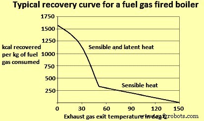
그림 1 스택 출구 온도가 다른 에너지 회수
저온 열 회수가 직면한 세 가지 과제가 있습니다. 이러한 과제는 다음과 같습니다.
저온 열교환 기술
낮은 온도의 폐열을 회수하기 위해 이슬점 온도 이하로 가스를 냉각할 수 있는 저온 열교환 기술을 사용할 수 있습니다. 기술 옵션에는 심층 이코노마이저, 간접 접촉 응축 회수, 직접 접촉 응축 회수 및 최근 개발된 수송 막 응축기가 포함됩니다. 이러한 기술의 상업화는 높은 비용과 시설이 회수된 열에 대한 최종 용도가 부족하기 때문에 제한적입니다. 시설에 폐열의 최종 용도가 부족한 경우 히트 펌프 및 저온 발전을 포함한 다른 회수 수단이 사용됩니다. 또한 이러한 기술은 경제적 제약으로 인해 제한을 받는 경우가 많습니다.
딥 이코노마이저 – 딥 이코노마이저는 배기 가스를 약 70°C로 냉각하고 표면에 침착된 산성 응축수를 견디도록 설계되었습니다. 이코노마이저의 설계는 다른 대안을 가질 수 있습니다. 이코노마이저의 콜드 엔드에 '쓰레기' 섹션을 설치할 수 있습니다. 콜드 엔드의 파이프는 시간이 지남에 따라 성능이 저하되며 매우 자주 교체해야 합니다. 교체 빈도는 연도 가스 구성과 건축 자재에 따라 다릅니다. 대안 중 하나는 스테인리스 스틸 파이프로 이코노마이저를 설계하는 것입니다. 스테인레스 스틸은 일반적으로 건설에 사용되는 연강보다 산성 가스를 더 잘 견딜 수 있습니다. 또 다른 설계에서는 대부분의 열교환기에 C 강을 사용하지만 산성 침전물이 발생하는 차가운 쪽에는 스테인리스 강 파이프를 사용합니다. 유리 파이프 열교환기(주로 공기 예열기와 같은 가스 가스 응용 분야) 또는 테플론과 같은 고급 재료를 사용하는 것이 다른 대안이 될 수 있습니다.
간접 접촉 결로 회복 – 간접 접촉 응축 회수 장치는 가스를 약 40℃로 냉각시킵니다. 이 범위에서 가스의 수증기는 거의 완전히 응축됩니다. 간접 접촉 교환기는 쉘 및 튜브 열 교환기로 구성됩니다. 스테인리스 스틸, 유리, 테플론 또는 기타 고급 재료로 디자인할 수 있습니다.
직접 접촉 결로 복구 – 직접 접촉 응축 회수에는 공정 흐름과 냉각 유체의 직접 혼합이 포함됩니다. 이러한 유형의 회수는 열이 전달되는 분리 벽을 포함하지 않기 때문에 간접 접촉 회수 장치에 필요한 큰 열 전달 표면의 몇 가지 문제를 피할 수 있습니다. 이러한 유형의 회수에서는 연도 가스가 열교환기에 들어갈 때 장치 상단에 도입된 냉수에 의해 냉각됩니다. 가열된 물 흐름은 교환기의 바닥을 통해 떠나 외부 시스템에 열을 제공합니다. 직접 접촉 응축의 문제는 물이 연도 가스의 물질에 의해 오염될 수 있다는 것입니다.
수송 멤브레인 콘덴서 – TMC(Transport Membrane Condenser)는 가스 배출 스트림의 수증기에서 물(물의 잠열과 함께)을 포착하는 개발 기술입니다. 물은 모세관 응축을 사용하여 이슬점 이상의 온도에서 연도 가스에서 추출되고 보일러 공급수로 재활용됩니다. 직접 접촉 열 회수에서와 같이 TMC는 연도 가스에서 직접 뜨거운 물을 추출합니다. 그러나 TMC는 멤브레인을 통한 수송을 통해 물을 회수하므로 직접 접촉 회수와 같이 회수된 물이 오염되지 않습니다. 이 기술은 천연 가스 연소 보일러의 깨끗한 배기 흐름에 대해 입증되었습니다. 그러나 TMC는 더 더러운 폐기물 흐름에 대한 광범위한 구현이 가능하기 전에 고급 재료에 대한 추가 개발을 요구합니다.
히트 펌프 또는 저온 폐열 업그레이드 – 위에서 언급한 열교환 기술은 고온에서 저온 최종 용도로 '내리막' 에너지의 흐름을 포함합니다. 이는 폐열 온도가 주어진 난방 부하에 필요한 온도보다 낮을 때 열 회수 기회에 제한을 둘 수 있습니다. 예를 들어, 폐열은 약 35°C의 온수 형태로 제공될 수 있지만 약 85°C의 온수가 필요합니다. 이러한 경우 열 펌프는 열을 원하는 최종 사용 온도로 '업그레이드'할 수 있는 기회를 제공할 수 있습니다. 열 펌프는 외부 에너지 입력을 사용하여 저온 소스에서 에너지를 흡수하고 더 높은 온도에서 이를 거부하는 사이클을 구동합니다. 디자인에 따라 히트 펌프는 두 가지 기능을 수행할 수 있습니다. 그들은 폐열을 더 높은 온도로 업그레이드하거나 흡수 냉각 시스템을 구동하기 위한 에너지 입력으로 폐열을 사용할 수 있습니다. 히트 펌프는 공정 산업에서 발견되는 저온 제품 스트림에 가장 적합합니다.
필요한 온도 차이와 연료 및 전기의 상대적 비용에 따라 열 업그레이드가 경제적일 수 있습니다. 시설에 폐열원보다 약간 높은 온도에서 열 부하가 있는 경우 추가 연료를 태워서 얻는 것보다 열 펌프가 열을 더 효율적으로 제공할 수 있습니다. 성능 계수(COP)는 열 출력 및 작업 입력에서 결정되고 방정식 COP =Q/W로 지정되는 열 펌프 성능의 측정값입니다. 여기서 Q는 열 펌프의 유용한 열 출력이고 W는 작업 입력입니다.
히트 펌프의 가능성을 결정할 때 중요한 고려 사항은 폐열 온도와 원하는 온도 상승입니다. 사용된 사이클 유형과 선택한 작동 유체 유형은 히트 펌프가 열을 받거나 거부할 수 있는 온도에 영향을 미칠 뿐만 아니라 도달 가능한 최대 온도 상승을 결정합니다. 원하는 온도 상승이 증가함에 따라 히트 펌프의 효율이 감소합니다.
폐쇄 압축 주기 – 폐쇄 압축 사이클에서 히트 펌프는 냉각수의 온도를 낮추는 데 사용되는 반면 추출된 열은 플랜트의 다른 곳에서 사용되는 공정수의 온도를 높이는 데 사용됩니다. 히트 펌프는 증발기, 압축기, 응축기 및 팽창 밸브로 구성됩니다. 증발기에서 에너지는 폐열원에서 냉매로 전달됩니다. 그런 다음 냉매는 압축기로 들어가 온도가 상승합니다. 과열된 냉매는 응축기로 들어가 열을 방열판으로 전달합니다. 마지막으로 냉매는 증발기로 돌아가기 전에 팽창 밸브에서 조절됩니다.
개방형 증기 재압축 – 개방 사이클 증기 재압축은 압축을 사용하여 폐증기의 압력(결과적으로 온도)을 높입니다. 기계적 증기 재압축은 기계식 압축기를 사용하는 반면 열 증기 재압축은 증기 이젝터를 사용하므로 기계적으로 구동되는 것이 아니라 열에 의해 구동됩니다.
흡수 열 펌프 – 흡수 열 펌프는 압축기가 더 복잡한 열 구동 흡수 메커니즘으로 대체된다는 점을 제외하고는 폐쇄 압축 사이클과 매우 유사합니다. 플랜트 요구 사항에 따라 시스템을 여러 가지 방법으로 구성할 수 있습니다. 한 가지 유형에서 히트 펌프는 더 낮은 온도와 더 높은 온도의 열 입력을 사용하여 중간 수준에서 열을 거부할 수 있습니다(예:낮은 온도 열 업그레이드). 다른 유형에서 히트 펌프는 중간 온도 입력을 사용하여 하나의 낮은 온도 스트림과 하나의 높은 온도 스트림에서 열을 거부할 수 있습니다. 이 두 번째 응용 프로그램은 에어컨 및/또는 냉장에 사용할 수 있습니다.
발전
폐열에서 전력을 생성하는 것은 일반적으로 보일러의 폐열을 사용하여 기계적 에너지를 생성한 다음 발전기를 구동하는 것과 관련됩니다. 이러한 전원 주기는 잘 발달되어 있습니다. 그러나 열전발전과 압전발전과 같이 열로부터 직접 전기를 생산할 수 있는 새로운 기술이 개발되고 있다. WHR을 위한 발전 기술을 고려할 때 염두에 두어야 할 중요한 요소는 다양한 온도에서 발전에 대한 열역학적 한계입니다. 발전 효율은 폐열원의 온도에 크게 의존합니다. 일반적으로 폐열에 의한 발전은 중온 내지 고온의 폐열원에만 국한되어 왔다. 그러나 대체 전원 사이클의 발전은 저온에서 발전 가능성을 높일 수 있습니다. 이러한 온도에서 최대 효율은 더 낮지만 이러한 방식은 폐열에서 많은 양의 에너지를 회수하는 데 여전히 경제적일 수 있습니다.
기계적 에너지를 사용하여 발전하는 세 가지 방법은 다음과 같습니다.
스팀 랭킨 주기 – 폐열 발전에 가장 많이 사용되는 시스템은 열을 사용하여 증기를 생성한 다음 증기 터빈을 구동하는 방식입니다. 전통적인 스팀 랭킨 사이클은 340℃ 이상의 온도를 가진 배기 스트림에서 폐열 회수를 위한 가장 효율적인 옵션입니다. 낮은 폐열 온도에서는 저압 스팀이 더 큰 장비를 필요로 하기 때문에 스팀 사이클이 비용 효율성이 떨어집니다. 더욱이, 저온 폐열은 증기를 과열시키기에 충분한 에너지를 제공할 수 없으며, 이는 증기 응축 및 터빈 블레이드의 침식을 방지하기 위한 요구 사항입니다. 따라서 저온 열회수 응용 분야는 증기에 비해 끓는점이 낮은 유체를 사용하는 유기 랭킨 사이클 또는 칼리나 사이클에 더 적합합니다.
유기적 랭킨 주기 – 유기 랭킨 사이클(ORC)은 증기 랭킨 사이클과 유사하게 작동하지만 증기 대신 유기 작동 유체를 사용합니다. 대안으로는 물보다 끓는점이 낮고 증기압이 높은 실리콘 오일, 프로판, 할로-알칸(예:프레온), 이소펜탄, 이소부탄, p-자일렌 및 톨루엔이 있습니다. 이를 통해 ORC는 훨씬 더 낮은 폐열 온도로 작동할 수 있습니다. 유체의 열역학적 특성은 다양한 온도에서 사이클의 효율성에 영향을 미치므로 가장 적절한 온도 범위는 사용되는 유체에 따라 다릅니다. 수증기와 비교하여 유체는 분자 질량이 더 높아 소형 설계, 더 높은 질량 흐름 및 더 높은 터빈 효율을 가능하게 합니다. 그러나 ORC는 낮은 온도에서 기능하기 때문에 전체 효율이 낮고 응축기 및 증발기의 온도에 따라 달라집니다. 효율은 고온 증기 발전소보다 낮지만 저온 사이클은 본질적으로 고온 사이클보다 효율이 낮다는 점을 기억하는 것이 중요합니다. 효율의 한계는 두 온도 사이에서 작동하는 열기관의 가능한 최대 효율인 Carnot 효율에 따라 표현할 수 있습니다. A Carnot engine operating with a heat source at 150 deg C and rejecting it at 25 deg C is only about 30 % efficient. In this light, a low efficiency in the range of 10 % to 20 % in case of ORC is a substantial percentage of theoretical efficiency, especially in comparison to other low temperature alternatives, such as piezoelectric generation, which are only 1 % efficient.
Although the economics of ORC, heat recovery need to be carefully analyzed for any given application, it is a useful alternative in those industries which do not have in-house use for additional process heat or no neighbouring plants which can make economic use of the heat.
Kalina cycle – The Kalina cycle is a variation of the Rankine cycle, using a mixture of ammonia and water as the working fluid. A key difference between single fluid cycles and cycles which use binary fluids is the temperature profile during boiling and condensation. For single fluid cycles, the temperature remains constant during boiling. As heat is transferred to the working medium (water), the water temperature slowly increases to boiling temperature, at which point the temperature remains constant until all the water has evaporated. In contrast, a binary mixture of water and ammonia (each of which has a different boiling point) increases its temperature during evaporation. This allows better thermal matching with the waste heat source and with the cooling medium in the condenser. Consequently, these systems achieve considerable greater energy efficiency. The cycle was invented in the 1980s.
Direct electrical conversion technologies
Whereas traditional power cycles involve using heat to create mechanical energy and ultimately electrical energy, new technologies are being developed which can generate electricity directly from heat. These include thermoelectric, thermionic, and piezoelectric technologies. However, these technologies are in development stage. A few have undergone some prototype testing in applications such as heat recovery in automotive vehicles.
Thermoelectric generation – Thermoelectric (TE) materials are semiconductor solids which allow direct generation of electricity when subject to a temperature differential. This technology is based on a phenomenon known as the Seebeck effect which states that when two different semiconductor materials are subject to a heat source and heat sink, a voltage is created between the two semi-conductors. Conversely, TE materials can also be used for cooling or heating by applying electricity to dissimilar semiconductors. Thermoelectric technology has existed for a long time (the thermoelectric effect was first discovered in 1821), but has seen limited use due to low efficiencies and high cost. Most TE generation systems in use have efficiencies in the range of 2 % to 5 %. These have mainly been used to power instruments on spacecraft or in very remote locations. However, recent advances in the nano-technology have enabled advanced TE materials which can achieve conversion efficiencies 15 % or higher.
In a recent study, it has been concluded that advanced TE packages are appropriate in medium to high temperature, high flow rate exhaust streams where facilities have little use for recovered waste heat. However, more development work is needed in this area. Low cost, high volume production methods for TE materials need to be developed in order to achieve this goal. Also, maintaining a high temperature differential across thin TE devices present a significant engineering challenge. Obtaining high heat transfer rates require advances in heat transfer materials and heat exchange systems with high heat transfer coefficients.
Piezo-electric power generation Piezo-electric power generation (PEPG) is an option for converting low temperature waste heat in the range of 100 deg C to 150 deg C to electrical energy. Piezo-electric technology converts mechanical energy in the form of ambient vibrations to electrical energy. A piezo-electric thin film membrane can take advantage of oscillatory gas expansion to create a voltage output. However, there are several technical challenges associated with PEPG technologies. These include (i) low efficiency (only around 1 % efficient), (ii) difficulties remain in obtaining high enough oscillatory frequencies (current devices operate at around 100 Hz, and frequencies needed are close to 1,000 Hz), (iii) high internal impedance, (iv) complex oscillatory fluid dynamics within the liquid/vapour chamber, (v) need for long term reliability and durability, and (vi) high costs.
While the conversion efficiency of PEPG technology is currently very low (1 %), there can be prospects to use PEPG cascading, in which case efficiencies can reach about 10 %. Other key issues are the costs of manufacturing piezoelectric devices, as well as the design of heat exchangers to facilitate sufficient heat transfer rates across a relatively low temperature difference.
Thermionic generation – Thermionic devices operate similar to thermo-electric devices. However, whereas thermoelectric devices operate according to the Seebeck effect, thermionic devices operate via thermionic emission. In these systems, a temperature difference drives the flow of electrons through a vacuum from a metal to a metal oxide surface. One key disadvantage of this technology is that it is limited to applications with high plying electricity to dissimilar semiconductors. Thermo-electric technology has existed for temperatures above 1,000 deg C. However, some development has enabled their use at around 100 deg C to 300 deg C range.
Thermo photo voltaic generator Thermo photo voltaic generators can be used to convert radiant energy into electricity. This technology involves a heat source, an emitter, a radiation filter, and a photo voltaic (PV) cell (like those used in solar panels). As the emitter is heated, it emits electro-magnetic radiation. The PV cell converts this radiation to electrical energy. The filter is used to pass radiation at wave-lengths which match the PV cell, while reflecting remaining energy back to the emitter. This technology can potentially enable new methods for WHR. A small number of prototype systems have been built for small burner applications and in a helicopter gas turbine.
WHR and iron and steel industry
The iron and steel industry employs several high temperature furnaces for coke, sinter, hot metal, and steel production and accounts for high energy consumption. While recovery from clean gaseous streams in the industry is common, heavily contaminated exhaust gases from coke oven, blast furnace (BF), basic oxygen furnace (BOF), and electric arc furnace (EAF) continues to present a challenge for economic WHR. Heat recovery techniques from these dirty gaseous streams are available, yet implementation has been limited due to high capital investment costs.
The steel industry has made the biggest progress in reducing its energy intensity. Such progress has been achieved by continuous casting and optimization of BF operation, and also through steel recycling and replacement of fossil fuels with recycled by-product gases (coke oven gas, blast furnace gas, and converter gas). In-situ waste heat recovery has been implemented wherever possible, for example, by recirculating hot flue gases inside the furnace where they were created to lower external energy demand, or by using hot flue gases to preheat combustion air or fuel gas. Such energy efficiency improvements still leave residual waste heat recovery opportunities, e.g. to produce steam for other parts of the process or to produce electricity.
WHR in case of steel plants is described below.
Coke production
Production of coke is an essential burden material for BF operation. Coke is produced in coke ovens, where coal is heated in an oxygen limited atmosphere. There are two methods for producing coke namely (i) the byproduct process, and (ii) the non-recovery process. In the byproduct process, chemical byproducts (crude tar, ammonia, and light oils) in the coke oven gas are recovered, while the remaining coke oven gas (COG) is cleaned and recycled within the steel plant. In the non-recovery process, the entire COG is burned in the process. The most common type of process is still the byproduct process and this is discussed below.
Byproduct cokemaking process has two areas of sensible heat loss namely (i) COG which is cooled in the gas cleaning process, and (ii) waste gas leaving the coke oven. The coke making process employs several coke oven chambers separated by heating flues. Recycled COG, and sometimes other gases such as BF gas, are used as the fuel source in the heating flue and supply heat to the oven chamber where coal carbonization takes place. As coal is carbonized in the oven chamber, gas and moisture (accounting for around 8 % to 11 % of charged coal) are driven off and leave through the pipes. The COG has a high heat content ranging from around 4000 kcal/cum to 4400 kcal/cum and hence it can be recycled for use as a fuel after undergoing a cleaning process.
The temperature of the crude COG at the oven outlet ranges from 650 deg C to 1000 deg C. At this point, the COG gas is a source of sensible heat. However, the heat is universally wasted due to the high amount of tar and other materials which can cause build up on heat exchanger surfaces. Upon leaving the oven, the COG is cooled by ammonia liquor spray followed by primary coolers. Different technologies are then used for removing tar, sulphur compounds, ammonia, and light oils. After cleaning, the COG is used as a fuel throughout the steel plant. In this arrangement, only the chemical energy of the COG is recovered when recycled, while the sensible heat is wasted.
While most of the steel plants do not employ heat recovery from COG, a limited level of heat recovery from COG is possible, as shown by the success of this practice in Japan. Coke oven facilities in Japan have successfully applied heat recovery through use of a low pressure heat transfer medium. In general, the minimum allowable temperature for the COG in the heat exchanger is around 450 deg C. At lower temperatures, tar condenses and leads to soot formation on the heat exchanger surface. Cooling to 450 deg C enables only about one third of the sensible heat to be recovered. However, it is unlikely that ISPs in other countries are going to pursue new technologies for heat recovery from crude coke oven gas. This is since ISPs are facing cost barriers with heat recovery from dirty exhaust streams. Also, the byproduct coke making process can become irrelevant in future years. It is likely that the ISPs are going to move away from the byproduct process to the non-recovery process due to environmental considerations. In the non-recovery process, the COG gas is burned within the process, and a WHB used to recover the sensible heat in the off gases.
Another source of sensible heat loss in coke ovens is the waste gases from the combustion of recycled fuel gases. The recycled fuel gases are used in the heating flue, which is adjacent to the oven chamber. Combustion of the fuel gases generates hot exhaust gases which leave the oven flue and pass through a regenerator to transfer heat to incoming combustion air and/or fuel. Waste gases leave the regenerator at temperatures averaging around 200 deg C. In some plants, the heat content of the waste gases are further recovered by use of a heat pipe or for preheating coal charge and reducing its moisture content. In this case, the temperature of the exhaust gases drops to around 60 deg C.
Production of sinter
Sintering plant consists of two major sections, sintering section and sinter cooling section. Heat recovery from both parts has been developed namely (i) from sintering section exhaust gas, and (ii) from cooling section cooling gas. There is large temperature difference depending on the position of the section. Average gas temperature in both sections is in the level of 100 deg C to 150 deg C, too low for effective heat recovery. Heat recovery is to be limited to high gas temperature zone, the final part of sintering section and primary part of cooling section, where gas temperatures of 300 deg C or higher are available. Although heat recovery zone is limited, the gas volume of sintering process is large enough for practical heat recovery.
The waste gas energy recovery system consists of hood, dust catcher, heat recovery boiler, circulation fan and de-aerator. Sintering machine exhaust gas is corrosive containing some dusts. Heat recovery is generally limited to high gas temperature zone as aggregated average temperature is low for heat recovery. At the same time, due to its corrosiveness, the gas temperature after heat recovery is to be kept above acid due point of the gas. Cooling gas is basically atmosphere air containing some dust. In case of sinter cooler, it is same as sintering machine heat recovery. Due to gas temperature distribution along with the cooler, heat recovery is limited to high gas temperature zone.
Sintering machine exhaust gas heat recovery can be categorized to circulation type and non-circulation type. In circulation type, gas after heat recovery are circulated to sintering machine as cooling gas replacement, whereas in non-circulation type, the gas after heat recovery is lead to gas treatment facility directly. Circulation type is adopted to improve heat recover efficiency.
In case of cooler heat recovery, the cooler gas is air. The cooler heat recovery system can be categorized as circulation type and non-circulation type. In case of non-circulation type, after heat recovery from hot gas zone, cooling gas is released to the atmosphere. In case of circulation type, after heat recovery from hot gas zone, cooling gas is led to cooler and reused for sinter cooling. Cooler gas temperature rises through recirculation and consequently results to higher heat recovery. On the other hand, cooling gas temperature rises up to the level of 180 deg C, cooling capability can decrease. Sinter temperature at outlet of the cooler is higher around 30 deg C in circulation type. Temperature difference is small enough and does not affect sinter plant operation. Recovered energy increases by 50 % in circulation type compared to non-circulation type. Fan power consumption is larger in case of circulation type. However, recovered power is far larger.
Hot metal production in BF
BF is one of the main units in ISPs. It converts iron ore into hot metal. Raw materials are charged from the top, including iron containing materials (lump iron ore, sinter, or pellets), additives (flux), and coke, while hot air and supplemental fuels are injected through tuyeres at the bottom of the furnace. The burden moves down through the BF and meets a rising current of hot gases. The hot air entering the BF is provided by several auxiliary hot blast stoves. In the hot blast stove, mixed gas consisting of BF gas (BFG) and COG are combusted. The heat from the combustion exhausts is transferred to a checker work regenerator. When the regenerator reaches an appropriate temperature, the flow of air is reversed and cold air is forced through the regenerator, which transfers heat to the cold air. The heated air is then injected into the furnace. The system operates according to the same principles as a regenerator used for heat recovery. However in this case, the regenerator is not a waste heat recovery unit, but rather the mechanism for transferring heat from the stove to the hot blast. Sources of off gas waste heat in BF include both the exhaust gases from the hot blast stove and the BFG leaving the BF.
There is sensible heat loss from BFG. New BFs are designed for efficient heat transfer, resulting into hot gases at the BF top in the low temperature range. The BFG is recovered for use as a fuel in blast air heating, rolling mill reheating furnaces, coke oven heating, power production, and steam generation. Since BFG has low calorific value, it is often mixed with COG or converter gas. BFG is required to be cleaned before it can be used as a fuel, and the sensible heat contained in the gas is rarely recovered. In some cases, BF operates at a sufficiently high pressure (2.5 atm or higher) to economically use a top pressure recovery turbine (TRT) for recovering of the pressure energy of the BFG. The gas is to be cleaned before entering the TRT, which is generally accomplished via wet cleaning, with the result that sensible heat of the off gas is lost. An alternative to wet cleaning technology is dry cleaning, in which the temperature of the gas entering the TRT can be raised to around 120 deg C. Dry type TRT technology is already working in several places. However, it is more expensive.
Another opportunity for WHR is from the combustion exhaust gases leaving hot blast stoves. The gases are at temperatures of around 250 deg C. The blast stove exhaust gas is relatively clean and is more compatible with heat recovery devices, making heat recovery from blast stoves a more common practice. The heat can be used to preheat combustion air and/or fuel gas. Heat exchangers used include rotary regenerators, fixed plate heat exchangers, and circulating thermal medium systems.
Production of liquid steel in BOF
BOF uses oxygen to oxidize impurities in the hot metal. Operation is semi-continuous:hot metal and scrap are charged to the furnace, oxygen is injected, fluxes are added to control erosion, and then the metal is sampled and tapped. The temperature required to melt the metal is supplied by the exothermic oxidation reaction and hence, no external heat source is needed.
The off gases from the BOF are at a high temperature. It has a high concentration of CO (carbon monoxide). Like COG and BFG, BOF gases offer opportunities for recovery of chemical energy and sensible heat. Challenges to WHR include high capital costs and the substantial maintenance problems resulting from hot dirty gases. Contaminants include iron oxides, heavy metals, SOx, NOx, and fluorides.
Various commercial methods for WHR are available. The two main methods for heat recovery are open combustion and suppressed combustion. In open combustion systems, air is introduced to the BOF gas duct to combust the CO. The heat generated is recovered with a waste heat boiler. In the suppressed combustion method, a skirt is added to the converter mouth to reduce air infiltration and combustion of the CO. The gas is then cleaned, collected, and used as a fuel. It is also possible to recover both the gas and the sensible heat via a combined boiler/suppressed combustion gas recovery system.
Liquid steel production by EAF
The steel industry has experienced significant growth in manufacture from recycled scrap via electric smelting. EAF and induction furnace are the two types of furnaces used to melt ferrous scrap for electric smelting. Out of these two, EAF is the prominent furnace. The furnace is refractory lined and typically covered by a retractable roof, through which C electrodes are lowered. Charge materials are lowered through the roof. Fluxes and alloying agents are also added to help control the quality of the material. The electrodes are then lowered to about an inch above the metal, and the current provides heat for melting the scrap. During furnace operation, several gases and particulate emissions are released, including CO, SOx, NOx, metal oxides, volatile organic compounds (VOCs), and other pollutants. Off gas temperatures at peak loads can equal anywhere from 1,350 deg C to 1,950 deg C. Exhaust gases are responsible for losses of around 20 % of the power input. Half of these losses are due to the chemical energy in the gases, while the other half is sensible heat. Additionally, around 8 % to 10 % of energy input is also lost to EAF cooling water jacket.
The most common method for heat recovery is scrap preheating, which has been widely used. The use of off gases to preheat scrap can save from 5 % to 10 % of total EAF energy consumption. Initial designs for scrap preheat required piping off gases to the charging bucket. Some of the challenges with these systems include the need to transport preheated scrap containing semi-burned non scrap materials (e.g., plastics), as well the evaporation of volatiles which create odour and environmental control problems. Alternatives to the bucket preheating system include the Consteel process, the Fuchs shaft furnace, and the Twin shell furnace. These processes have been installed at various places.
The Consteel process involves continuous charging of scrap and uses a scrap conveyer, a feeding system, and a preheater. The preheater is a refractory lined tunnel where off gases flow opposite the flow of scrap charge. Air is introduced into the preheater to burn the CO and CO2 and thus both the chemical and sensible heat in the off gas is used. An afterburner is sometimes installed to burn remaining CO and other compounds.The Fuchs shaft furnace involves a shaft immediately above the arc furnace roof. The charge is loaded via baskets in three stages. The baskets are refractory lined and designed with a seal which prevents the escape of fumes. Scrap heating is further assisted by auxiliary oxy-fuel burners. Additionally, afterburners are installed to completely combust all the CO. One additional benefit of the system is that charge acts as a dust filter, capturing around 40 % of the dust and returning it to the furnace, thus enabling slight increases in yield.
The benefits and drawbacks of scrap preheating systems depend on the specific operation. In some cases, it enables reduced electricity consumption and increased productivity. In other cases, scrap preheating systems are difficult to maintain. As EAFs become increasingly efficient and tap to tap times are reduced, scrap handling can reduce productivity and possibly create burdensome maintenance demands. In one case, the energy savings enabled by scrap preheating are reduced by about one half when tap to tap times are reduced by a third.
Power plant boilers
Boilers in ISPs normally use BFG and COG as fuel. The exhaust gas temperature for the boilers varies with the boiler’s age and the controls used. Temperatures can be fairly high (340 deg C to 450 deg C), with O2 content varying from 3 %7.5 %. The waste heat is in the form of clean, contamination-free gases and does not require further conditioning. The areas of waste heat and recovery from boilers and steam systems include (i) use of exhaust gases to preheat BFG and COG, (ii) use of low-temperature power generation if economically justifiable, (iii) preheating service water or river water for use in the plant, if possible and required, and low-pressure steam can be condensed and reused for the boiler water system instead of venting.
Reheating furnace
Reheating furnace is a key equipment of the hot rolling mills. Its function is to continuously heat billets, slabs or blooms of different sizes and grades upto 1,250 deg C. Most of the new reheat furnaces are walking beams furnaces (WBF). On the WBF, the heating is done over and under the products which are handled from charging side to discharging side by means of insulated and cooled beams (skids). A key performance criterion for reheating furnaces is heating homogeneity. 20 % to 30 % of the energy input is typically wasted divided between several thermal losses namely (i) the temperature of the exhaust gas between the combustion air recuperator and the stack is at 250 deg C to 300 deg C with natural gas fuel and higher with lower calorific value fuel, (ii) the product handling systems inside the furnace with skids and post cooling system, and (iii) wall and doors losses, hardly recoverable.
Water is used to constantly cool the skid system which is in contact with a very hot atmosphere in the furnace. This water loop typically enters at 40 deg C and is heated by 15 deg C before being directed to a dedicated cooling system.
At several places, WHR is carried out on the skid cooling system by producing steam when it is needed in the plant for other purposes. On its own, this installation reduces losses through the skid system because of the use of water cool pipes used at higher temperature. If steam is not needed by the plant then an ORC (adapted for such temperatures around 200 deg C) can be installed on the steam circuit to produce electricity. This installation has the benefit of being easily and safely operable especially with high variability of the losses because of the constant temperature brought by the water phase change. Most of the time, this technology is not installed because of long payback, and the energy contained in exhaust gases is wasted.
An electricity production system is possible to recover energy from exhaust gases. Depending on the heat source temperature, either a water-steam cycle (with low efficiency furnace) or an ORC (with better efficiency) are available. However, most of the time those technologies are not installed because of their long payback. This situation can have another solution. This solution combines heat from the skid cooling loop operated at higher pressure and temperature so as to produce a mixture of steam and water at around 215 deg C in a closed loop and heat from exhaust gases. The two heat sources are recovered separately thanks to organic heat fluid loops and then combined to form a common heat source.
The heat fluctuation from the exhaust gases (temperature and volume are modified) in case of furnace power variations (production or product variations) are balanced because of the constant temperature of the heat coming from the skid cooling system. Thus operation of the system is easy and makes the global heat source more stable especially with high fluctuations.
It is possible that the reheat furnace production can fluctuate in few minutes, which affects the heat content of exhaust gases entering the WHR system. The ORC is a rather flexible system which can accommodate such variations upto a certain point. An ORC can typically operate down to 30 % of its nominal capacity, and automatically shuts down when the heat input goes below that threshold. However, the economic aspect is affected as electricity production also decreases as well.
Heat storage solutions can be adapted to daily variations are becoming available for industrial applications and can be used in combination with an ORC to flatten its production. Oil is, for instance, is appropriate heat storage medium at that temperature level. Economic benefits need to be assessed on a case by case basis.
Waste heat from solid streams
In addition to waste heat losses from off gases, solid streams and cooling water are sources of additional sensible heat losses. Solid products and byproducts with significant waste heat losses include hot coke, hot sinter, BF slag, BOF slag, cast steel, and hot rolled steel. Though the heat from solid streams are often more difficult to recover, the heat losses are high. The sensible heat loss from coke is recovered in some plants coke dry quenching (CDQ) as an alternative to wet quenching. CDQ involves catching incandescent coke in a specially designed bucket, which is discharged into the CDQ vessel. An inert gas such as nitrogen passes over the coke and recovers its sensible heat. The hot gas is then passed through a waste heat boiler. Energy saving is in the range of 0.2 million to 0.25 million kcal per ton of coke. There have also been attempts to recover heat from other solid flows via radiant heat boilers. This was unsuccessful for BF and BOF slag, but has been commercialized for recovering heat from cast steel in a few locations in Japan and Germany.
Another option for reducing heat losses from cast steel is hot charging, in which cast products are charged to the reheating furnace while still hot. Hot charging can save about 0.12 million kcal per ton. Sensible heat loss from hot rolled steel can also be partially recovered by using water cooling. Since the final temperature of the cooling water is generally low (around 80 deg C), it can be upgraded for other heating applications with a heat pump.
제조공정
열처리는 재료의 물리적 및 기계적 특성을 변경하기 위해 금속을 가열 및 냉각하는 결합된 공정으로 정의됩니다. 열처리는 주조 금속 합금을 균질화하여 매우 높은 온도에서 작업 능력을 향상시키고 원하는 기계적 특성을 달성하는 방식으로 미세 구조를 변경하는 데 사용됩니다. 열처리 공정을 진행하기 위해서는 처리하는 사람의 안전이 최우선입니다. 이 과정에서 많은 양의 열이 방출되면 문제가 발생할 경우 매우 심각한 문제가 발생할 수 있기 때문입니다. 열처리 공정은 요구 사항에 따라 온도가 변하는 용광로 및 오븐에서 수행되고 공정에 금속이 수행되
혁신 일상 생활에서 점점 더 중요해지고 필요하게 되면서 우리 사회와 경제 모델의 기본 기둥 중 하나가 되었습니다. 혁신은 일반적으로 더 나은 성능의 신제품 개발과 관련이 있습니다. 그러나 혁신은 예를 들어 자원의 더 나은 사용과 같은 다른 목표와 함께 적용될 수도 있습니다. , 쉽게 재사용할 수 있는 제조 제품 또는 쓰레기 감소를 생산하는 새로운 공정 설계 . 이러한 유형의 혁신을 에코 혁신이라고 합니다. . 오늘 블로그에서는 에코이노베이션이 무엇을 구성하는지, 그 목표, 어떻게 수행할 수 있는지, 에코이노베이션을 적용하는 기업과