

제조공정

산업 제조
 |
| × | 1 | |||
| × | 1 | ||||
 |
| × | 1 | |||
 |
| × | 1 | |||
| × | 1 | ||||
| × | 1 | ||||
| × | 1 | ||||
| × | 1 | ||||
| × | 1 | ||||
 |
| × | 1 | |||
| × | 1 | ||||
 |
| × | 2 | |||
| |
| × | 1 | |||
| × | 2 | ||||
| × | 1 | ||||
| × | 1 | ||||
| × | 1 | ||||
| × | 1 | ||||
 |
| × | 1 | |||
| × | 4 | ||||
| × | 8 | ||||
 |
| × | 4 | |||
| × | 1 | ||||
| × | 1 | ||||
| × | 1 | ||||
| × | 1 | ||||
| × | 1 | ||||
| × | 1 | ||||
| × | 1 | ||||
| |
| × | 12 | |||
| × | 1 | ||||
| × | 1 | ||||
| × | 1 | ||||
| × | 1 | ||||
| |
| × | 7 |
 |
| |||
 |
| |||
 |
| |||
|
| ||||
 |
| |||
|
업데이트:MagPi Magazine, Issue No. 105
영감
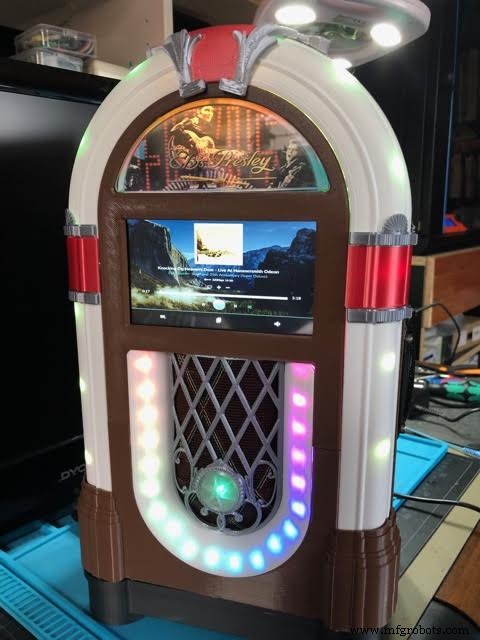
저는 수년간 클래식 주크박스와 사랑에 빠져 있습니다. 2014년까지만 해도 하나 만들려고 했는데 잘 생긴 빌드가 없어서 못 만들었어요. 3D 프린팅 및 디자인 기술을 배운 오늘로 빨리 가십시오.
열정, 호기심, 열망이 이러한 노력을 이끌었습니다. 이와 같은 미니 주크박스를 갖고 싶다고 생각한다면 많은 대중 시장 제품이 있습니다. 저렴, $65 USD에 이 탁상용 Victola 모델처럼. Hackster 메이커 플라잉엔젤은 훌륭한 주크박스 빌드를 가지고 있습니다. 반면에 더 큰(105cm/41.3 in H) 기성품 현대 주크박스가 있지만 훨씬 더 비싼 $795 USD입니다. 비용 확인 및 노력 이 프로젝트에 얼마나 참여했는지 보려면 아래 섹션을 참조하십시오.
속성
이 프로젝트는 Grabcad에서 Marco Gregorio의 뛰어난 3D 주크박스 디자인 없이는 불가능했을 것입니다. Marco에게는 모델링할 실제 주크박스가 없었기 때문에 더욱 놀랍도록 디테일한 작품입니다. 인터넷에서 찾을 수 있었던 것뿐입니다! Marco의 작업을 확인하는 것은 스스로에게 빚이 있습니다...
또한 주크박스에 필수적인 것은 LED 조명을 음악에 맞게 만드는 데 사용되는 Arduino 코드입니다(Learn.sparkfun.com의 Michael Bartlett).
개요
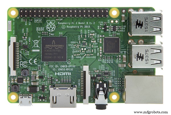
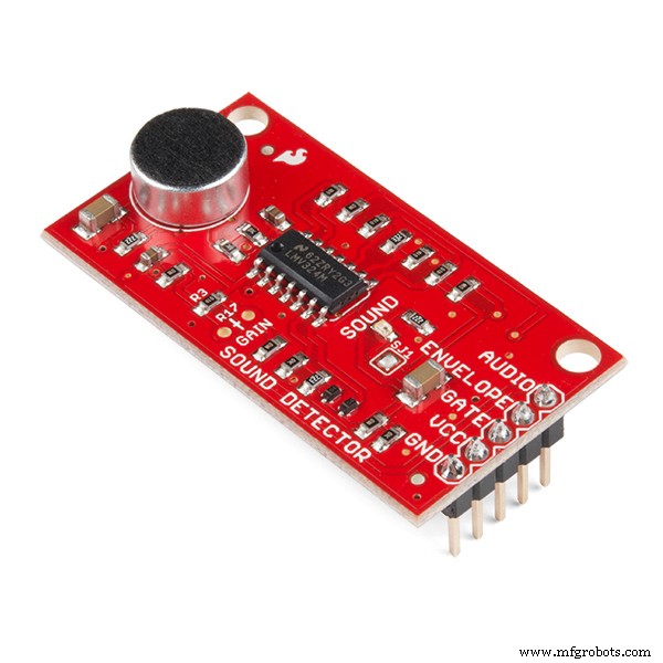
이것은 무료 Volumio 소프트웨어로 구동되는 음악 플레이어입니다. Volumio는 AirPlay, Spotify, Pandora, 웹 라디오 및 컴퓨터, 태블릿 또는 휴대폰에서 제어하는 자신만의 음악을 제공합니다. 다운로드하여 설치하기만 하면 됩니다. 내가 무엇을 추가 했습니까? 3D 케이스, 터치 패널 LCD, 음악에 맞춰 켜지는 LED. LCD는 Raspberry Pi 3 또는 4에서 전원이 공급됩니다. LED는 Raspberry Pi 및 IQAudio Pi Digi Amp와 같은 하드웨어 스택 상단에 부착된 Adafruit Perma-Proto 보드의 Arduino Micro에 의해 제어됩니다.
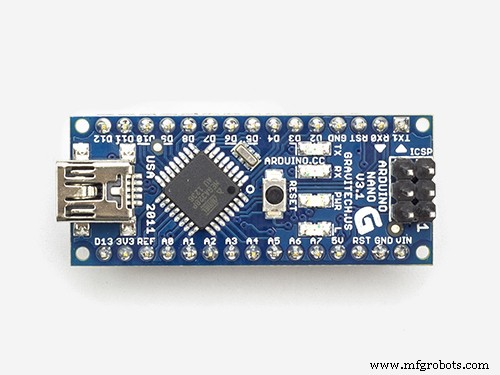
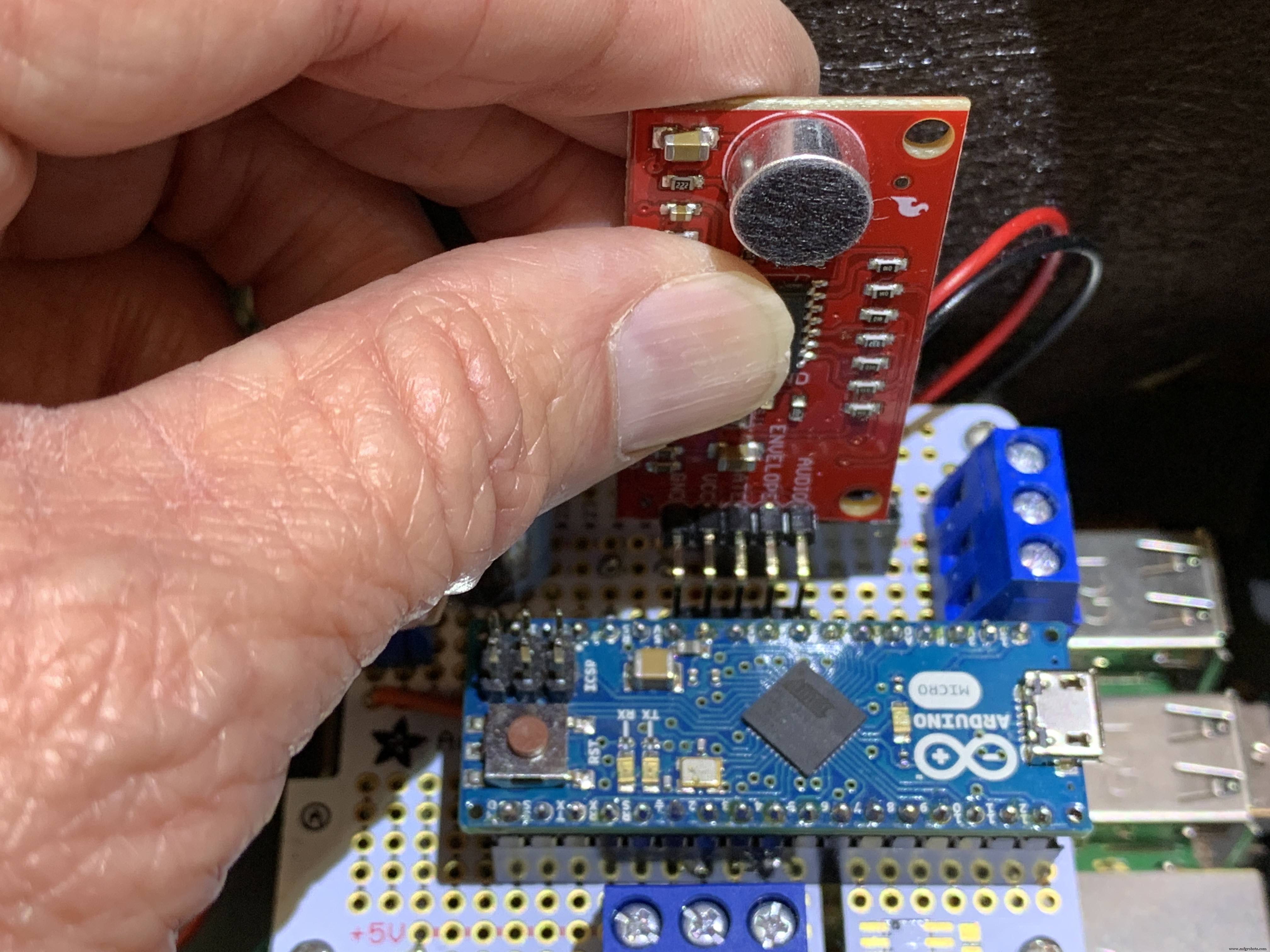
인벤토리에 있던 오래된 하드웨어, IQAudio 앰프 보드 및 Arduino Micro를 사용하고 있습니다. 이 글을 쓰는 시점에서 IQAudio는 이제 Raspberry Pi의 일부이며 Pi Digi Amp Plus는 여전히 사용할 수 있으며 내가 지불한 것보다 저렴합니다. Arduino Micro는 더 이상 사용되지 않지만 Arduino Nano 또는 Adafruit Itsy-Bitsy를 사용할 수 있습니다. 아날로그 및 디지털 핀 사용을 조정하고 Digi Amp에서 도터 보드(Arduino)로 5V 전원을 공급해야 합니다. 마지막으로 Sparkfun Sound Detector는 마술처럼 소리를 디지털 비트로 변환합니다.
Marco는 내가 Fusion 360 3D 설계 응용 프로그램으로 가져올 수 있는 주크박스의 모든 구성 요소에 대한 STEP 파일을 제공했습니다. 내가 한 일은:
<울>
디자인 목표 <울>
기술 수준:고급 <울>
비용:비싸다
(모든 비용은 USD)
최소한:
<울>또는
<울>HDMI 케이블/커넥터, 스위치, 마운팅 하드웨어, 점퍼 와이어, 암 헤더 등에 대해 40달러 이상을 추가로 계산하십시오. 재고가 많이 있었습니다. 제 경우, 현재 현금 지출 비용은 약 $150이었고, 수개월에 걸쳐 너무 많은 물품을 보유하고 있었기 때문입니다. 당신이 나가서 그 모든 용품을 사야 한다면... 글쎄, 당신이 계산을 해야 합니다.
저에게는 그만한 가치가 있었습니다.
노력
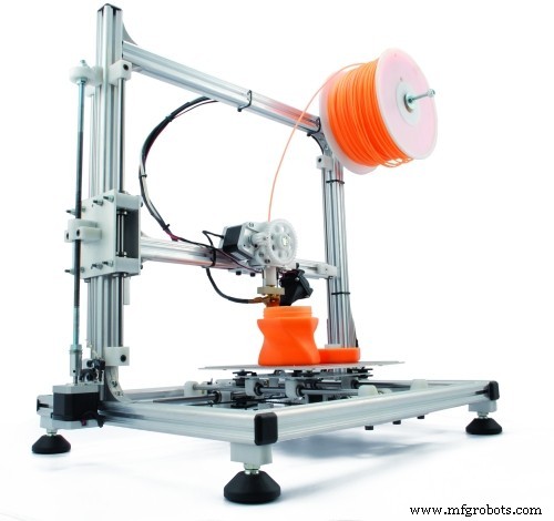
3D 프린트는 프린터에 따라 75시간 이상이 소요됩니다. 인쇄하는 데 몇 시간이 걸리는 약 12개의 다른 부품이 21개 있습니다. 나머지 부분은 각각 1-2시간 정도 소요됩니다. 그리고 그것은 다시 할 인쇄가 없다고 가정합니다.
저는 핫 글루를 사용하여 4단계로 케이스의 섹션을 함께 준비하고 접착했습니다. 3-4시간을 가정합니다. 그에 대한. LED 스트링을 붙이려면 설정 및 실행에 약 1시간이 걸립니다. 또한 주크박스를 완성하기 위해 작은 장식 부품(CA 접착제 사용)을 정밀하게 접착합니다.
전자 제품의 경우 다음을 위해 최소 5시간을 계산하십시오.
<울>최종 접착에는 1-2시간이 소요될 수 있습니다.
요약하면 모든 부품을 인쇄하는 시간 외에 조립에 약 12시간 이상이 소요될 수 있습니다.
다운로드
문서, 코드 및 3D 인쇄 파일은 github에서 사용할 수 있습니다.
3D 프린트 파일은 thingiverse에서도 사용할 수 있습니다.
3D 프린팅
총 21개의 개별 STL 부품 파일이 있습니다. 일부 부품은 2부/인쇄물이 필요합니다.
시작하기
"사물" 섹션의 주석을 주의 깊게 읽으십시오. 그들은 사용할 정확한 구성 요소에 대한 필요한 정보를 제공합니다. 부품을 교체하는 경우 변경해야 할 사항을 파악해야 합니다.
모든 것이 제대로 작동하는지 확인하려면 케이스를 조립하기 전에 모든 전자 장치가 함께 작동하는지 테스트하십시오.
<울>
Volumio 설치
Volumio 시작하기 페이지로 이동하여 Raspberry Pi에 대한 설정 가이드를 따르십시오. 테스트를 시작하려면 아래 사진과 같이 IQAudio Pi Digi Amp를 Raspberry Pi에 장착하고 Amp를 Pi의 암 헤더에 연결한 다음 Pi에서 IQAudio Amp까지의 스탠드오프를 사용하세요. 나중에 이 가이드를 참조하여 3D 프린팅된 주크박스 바닥에 장착하세요.
_9H4kWWGtUT.jpeg?auto=compress%2Cformat&w=680&h=510&fit=max)
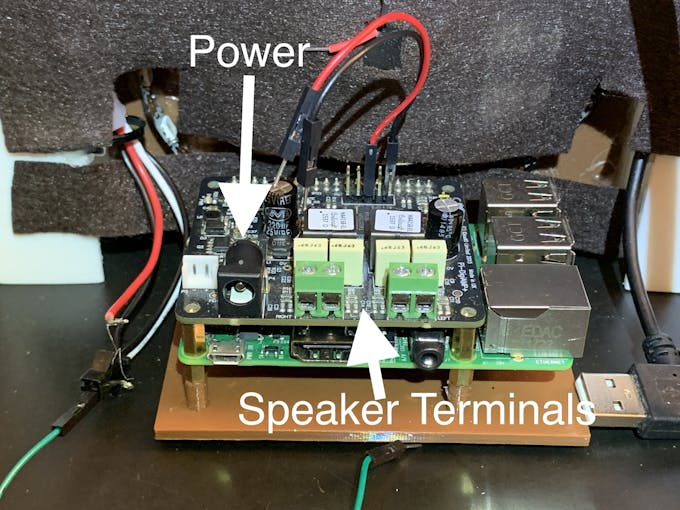
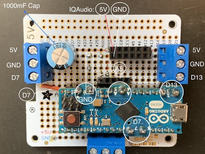
아래 사진과 같이 2개의 암-수 점퍼 와이어를 Digi Amp Plus의 +5V 및 GND 단자에 연결합니다. 이들은 Perma-Proto 보드에 연결되어 Pi Digi Amp Plus에서 직접 NeoPixels에 전원을 공급합니다.
최신 모델 Digi Amp에는 Pi의 모든 헤더 핀이 노출되어 있으므로 5V 및 GND 핀이 표준 Pi 헤더 핀 위치에 있습니다.
_4dxCv32yCp.jpeg?auto=compress%2Cformat&w=680&h=510&fit=max)
스피커를 설정하려면 두 쌍의 스피커 와이어(14-26 AWG)를 약 7in/18cm 길이로 잘라 스피커 터미널과 IQAudio 나사 터미널에 연결합니다. Pi는 IQAudio에서 전원을 공급받습니다. 하지 마십시오. Pi 전원 잭에 전원을 연결합니다. IQaudio에 전원 브릭을 연결하고 volumio에서 웹 라디오를 재생해 보세요.
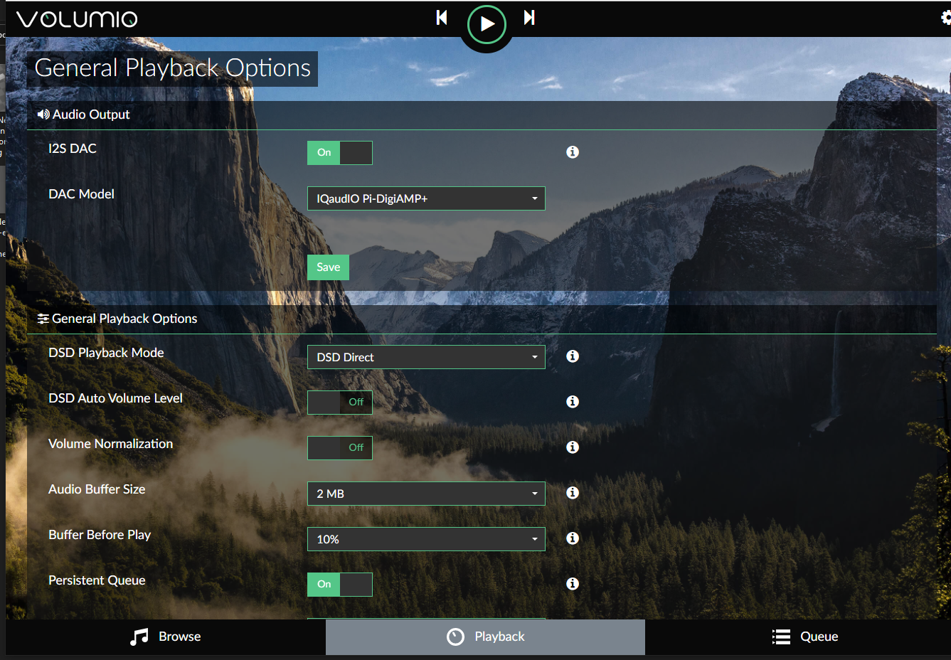
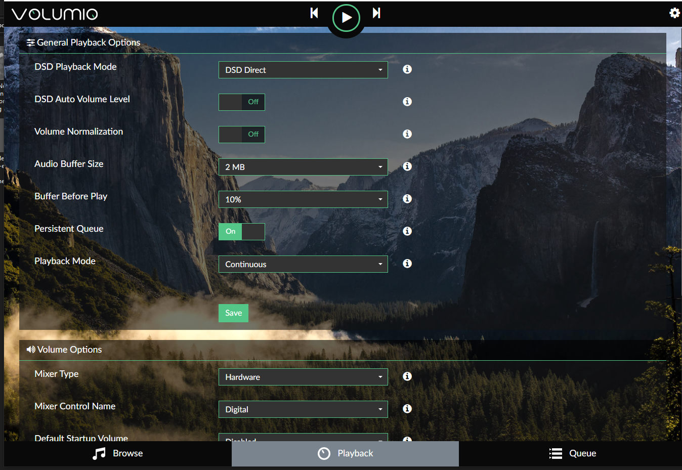
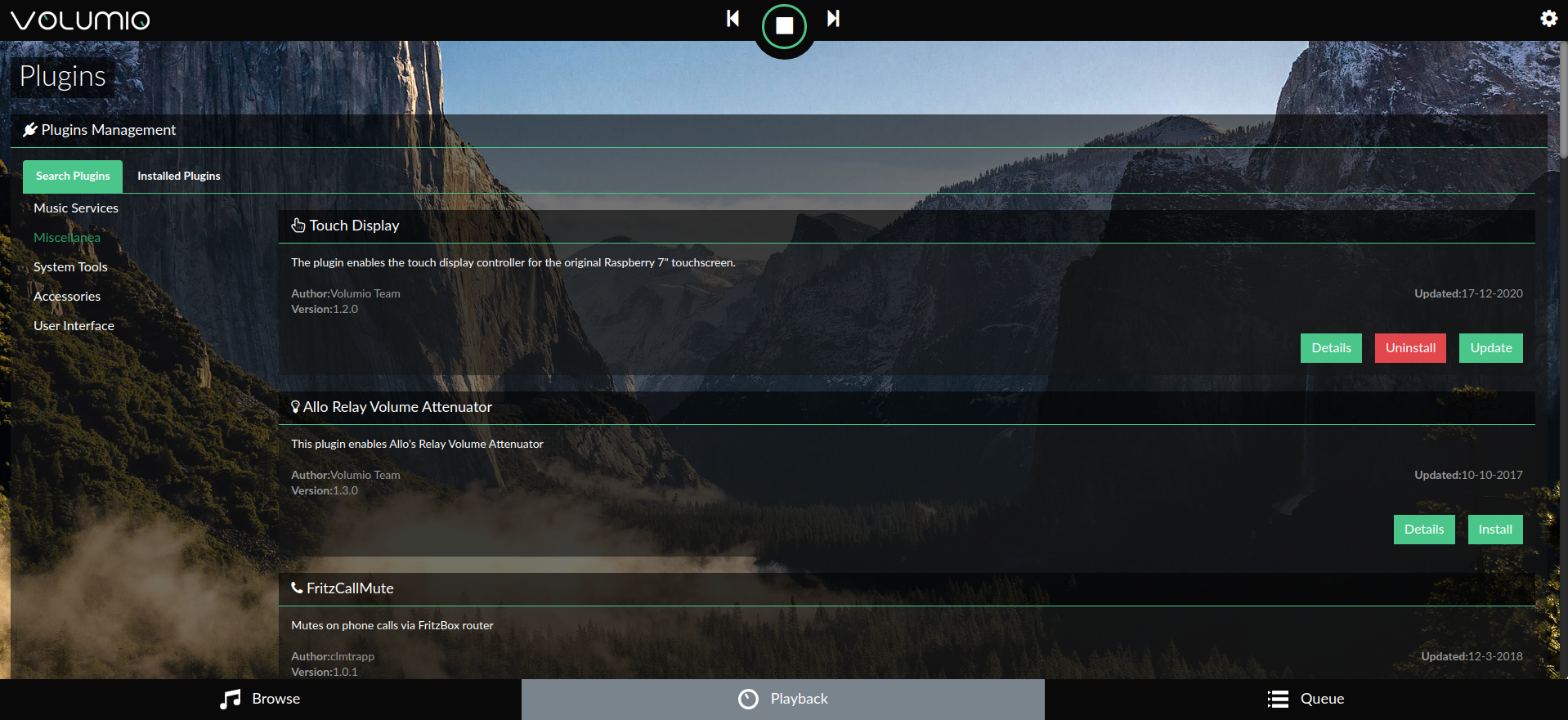
아래 갤러리는 IQAudio Pi Digi Amp Plus 및 터치 스크린 플러그인(설정/플러그인/기타)에 대한 Volumio 설정을 보여줍니다.
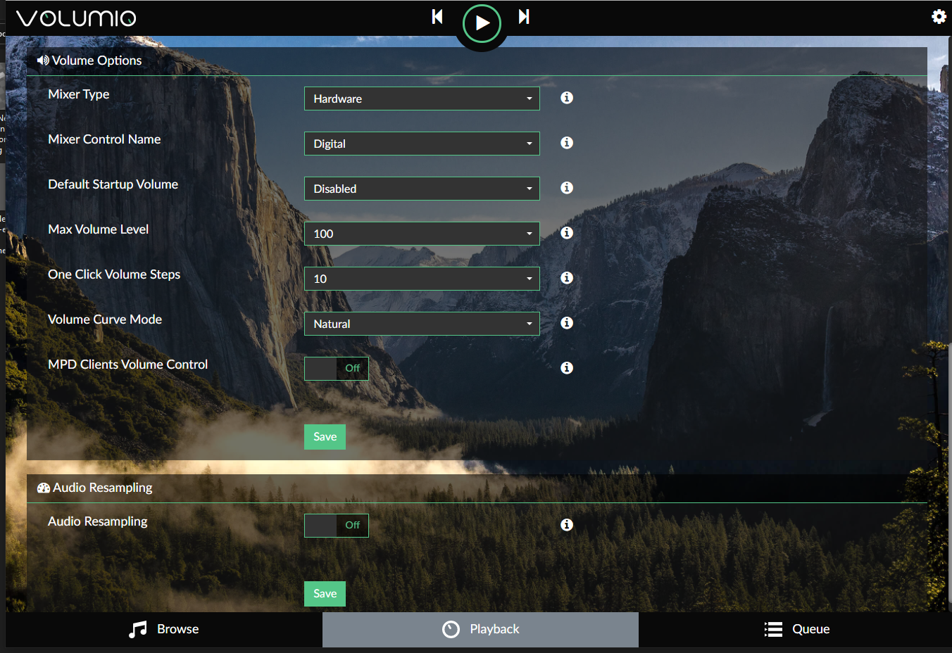
Volumio 사용을 시작하려면 빠른 시작 가이드와 Volumio의 첫 단계를 확인하십시오.
회로 기판 준비
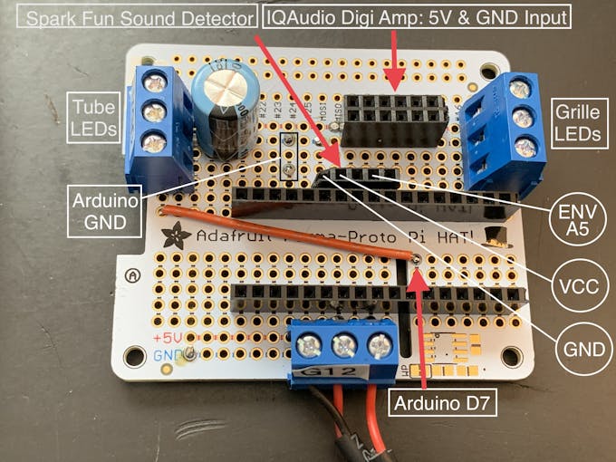
Adafruit Perma-proto 보드의 폼 팩터는 Pi 및 IQAudio 앰프 위에 쌓였을 때 잘 맞고 Arduino를 위한 좋은 캐리어/도터 보드가 되었습니다.
보드는 전원을 위해 IQAudio 5V 및 GND에만 연결됩니다. 따라서 Pi에 연결하는 일반적인 암 헤더는 사용되지 않았습니다.
프로토 보드에서 사용 가능한 공간을 최대한 활용하려면 "3.3V"라고 표시된 레일이 상단에 오도록 보드의 방향을 지정합니다.
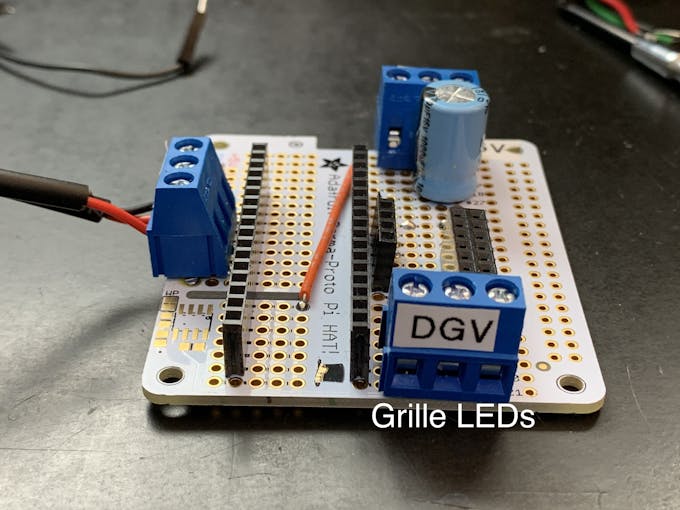
저는 점대점으로 배선하는 것보다 조금 덜 일반적인 방식으로 프로토보드를 수정하고 있습니다.
<울>이러한 것들은 채워졌을 때 잘 구성된 보드에 기여했습니다.
배선 연결 및 수정에 대해서는 이 사진 갤러리를 참조하십시오.
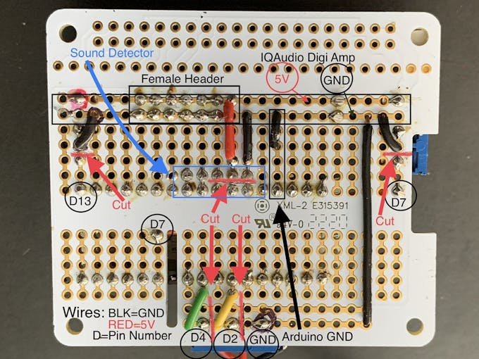
참고: 3핀 단자의 핀 간 피치는 5.08mm입니다. 이는 proto 보드의 표준 2.54mm 비아 피치의 정확히 2배입니다. 따라서 나사 단자/핀은 각각 2개의 보드 비아로 떨어져 있습니다. 보드 레이아웃 및 트레이스 절단은 해당 간격에 따라 다릅니다. 보드 레이아웃을 변경하지 않고는 3핀/2.54mm 피치 단자를 대체할 수 없습니다.
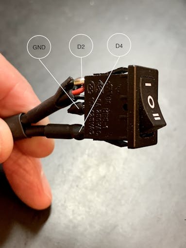
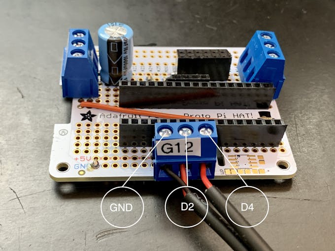
애니메이션 선택 스위치
또한 사진과 같이 3위치 로커 스위치를 배선해야 합니다. 이 스위치용으로 약 7in/18cm의 연결 와이어 3개를 자릅니다. 가급적이면 검정색(GND) 2개와 빨간색(+V) 1개를 사용하는 것이 좋습니다.
이 스위치에 대한 자세한 내용은 아래를 참조하세요.
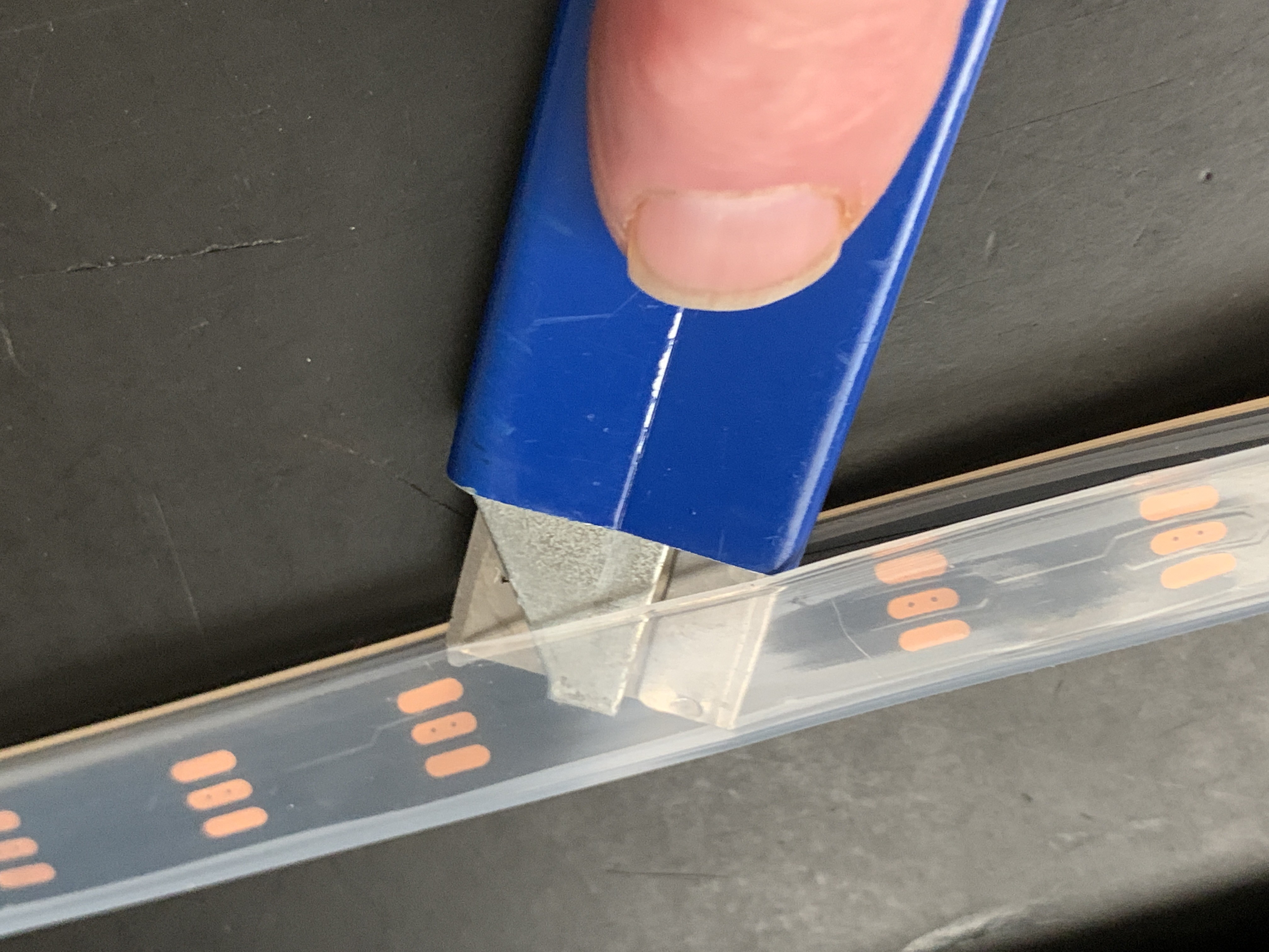
네오픽셀
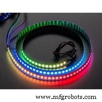
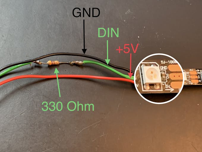
1미터 네오픽셀 스트링에서 실리콘 덮개를 제거합니다. Neopixel 스트립을 36개 LED와 22개 LED의 두 부분으로 자릅니다. 짧은 스트립이 전면 그릴을 둘러쌀 것입니다. 36개의 LED 길이 스트립은 외부 튜브(네온 튜브)에 있습니다. 각 끈에 대해 약 7인치/18cm의 연결 와이어 3개를 자릅니다(나중에 줄일 수 있음). 각 섹션을 GND, +V 및 DIN용 와이어로 배선하고 스트링의 DIN 방향과 일치하도록 합니다. DIN 연결(330옴 작동)과 인라인 저항을 추가합니다.
별빛
전면 그릴에는 6각 별(Star Light) 모양의 3D 프린팅 인서트가 있습니다. 이 Star Light 뒤에 +V 및 GND 마운트를 사용하는 RGB 슬로우 페이드 LED는 빛 번짐을 방지하기 위해 3D 인쇄 배플에 삽입됩니다. +V 점퍼 와이어에 인라인으로 120옴 저항을 패치합니다. 이것은 LED에 대한 전류를 5V에서 약 3.4V로 떨어뜨릴 것입니다. 이것은 아래의 조립/그릴 천 섹션에서 사용됩니다.
아두이노
Arduino IDE를 아직 설치하지 않았다면 다음 지침에 따라 다운로드하여 설치하세요.
LED가 작동하려면 네오픽셀 라이브러리가 필요합니다.
소리에 반응하는 Neopixels는 Sparkfun의 Michael Bartlett이 그린 Interactive LED Music Visualizer 스케치를 기반으로 합니다. 버튼 없이 "Full Visualizer"를 사용하고 세 가지 기능이 있는 로커 스위치를 추가했습니다.
<울>스위치가 연결되어 있지 않으면 LED가 작동하지 않습니다.
github에서 Jukebox LED 스케치를 다운로드하세요.
연결
<울>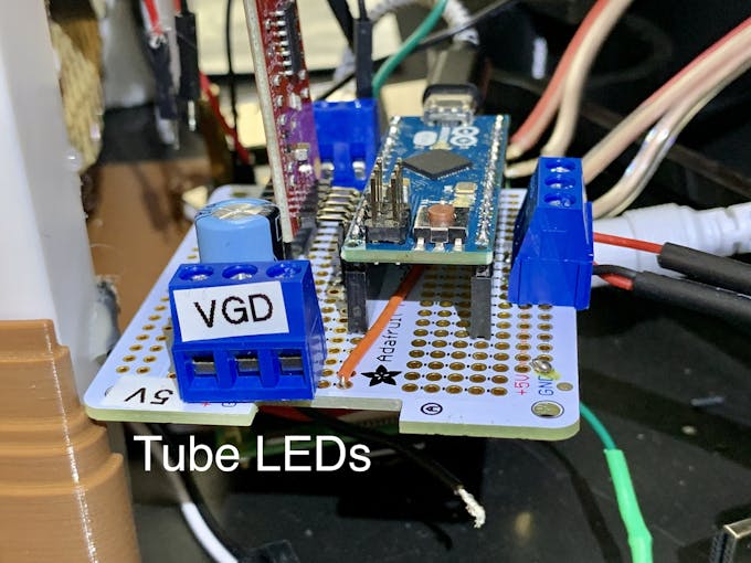

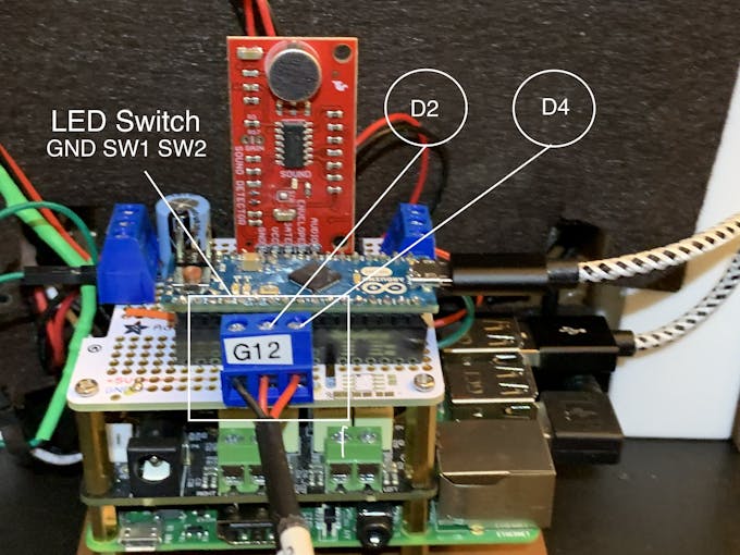
주크박스 LED 스케치를 Arduino 보드에 업로드합니다. 그릴 LED는 스케치 설정 기능에서 RainbowCycle 루틴을 실행하는데 약간의 시간이 걸립니다. 따라서 사운드 반응성 LED는 즉시 작동하지 않습니다. 설정 기능이 실행된 후 그릴 LED는 로커 스위치의 위치에 영향을 받지 않고 항상 켜져 있습니다. With music playing from Volumio, the Neon tubes should react to music with the 3-position rocker switch set to position one. Switch position two passes a color-wheel/chaser pattern through the Neon tubes. Center position on this switch turns the Neon LEDs off.
3D 프린팅
Check the docs folder of the github download for part identification (Parts List) and Print Times for each part. There are also screenshots of the Prusa Slicer parameters and orientation to guide how to print each part. Find those in the 3D-Prints folder.
참고: All images are of the prototype jukebox I built. These will look different from the published Fusion 360 design archive and STL files. The final release STL files include improvements for the following:
<울>
어셈블리
Tools
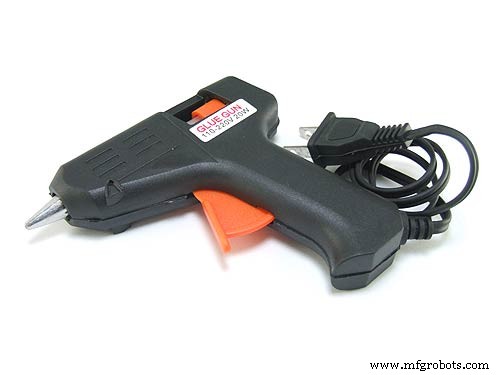
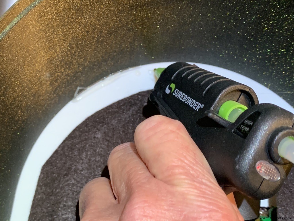
I used a fine-tipped hot glue gun so I could get into smaller spaces. These use smaller diameter glue sticks, and lots of them.
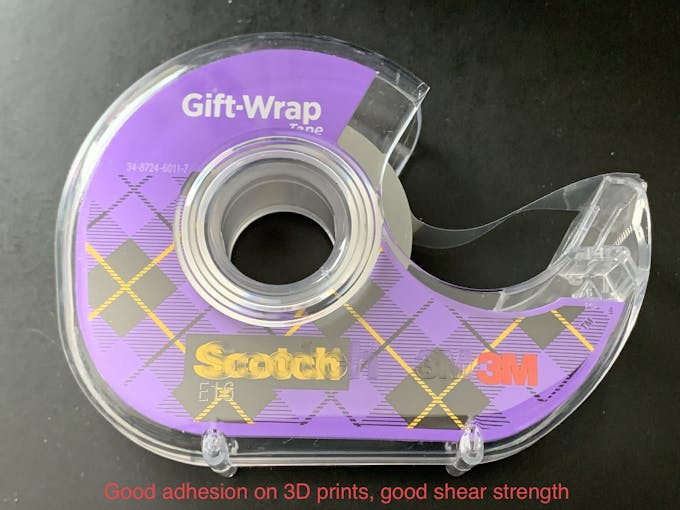
I used some tape I had on hand to temporarily hold the parts together for gluing. I found Scotch Gift-Wrap tape was actually pretty good for this. It has good adhesion and strong shear strength.
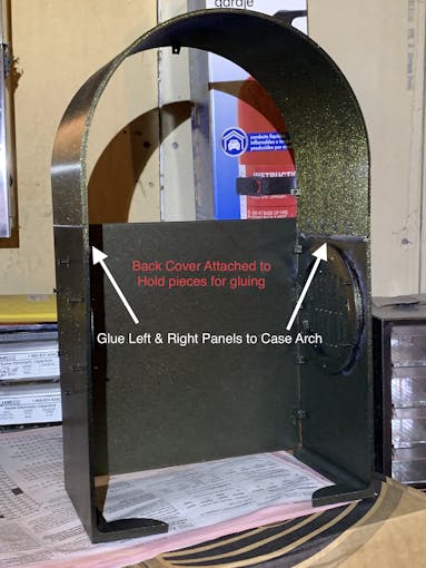
인클로저
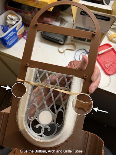
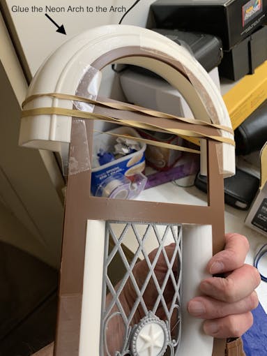
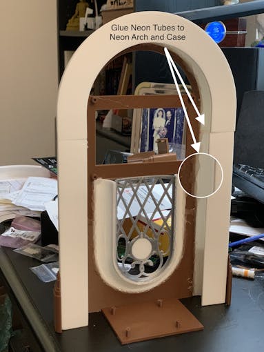
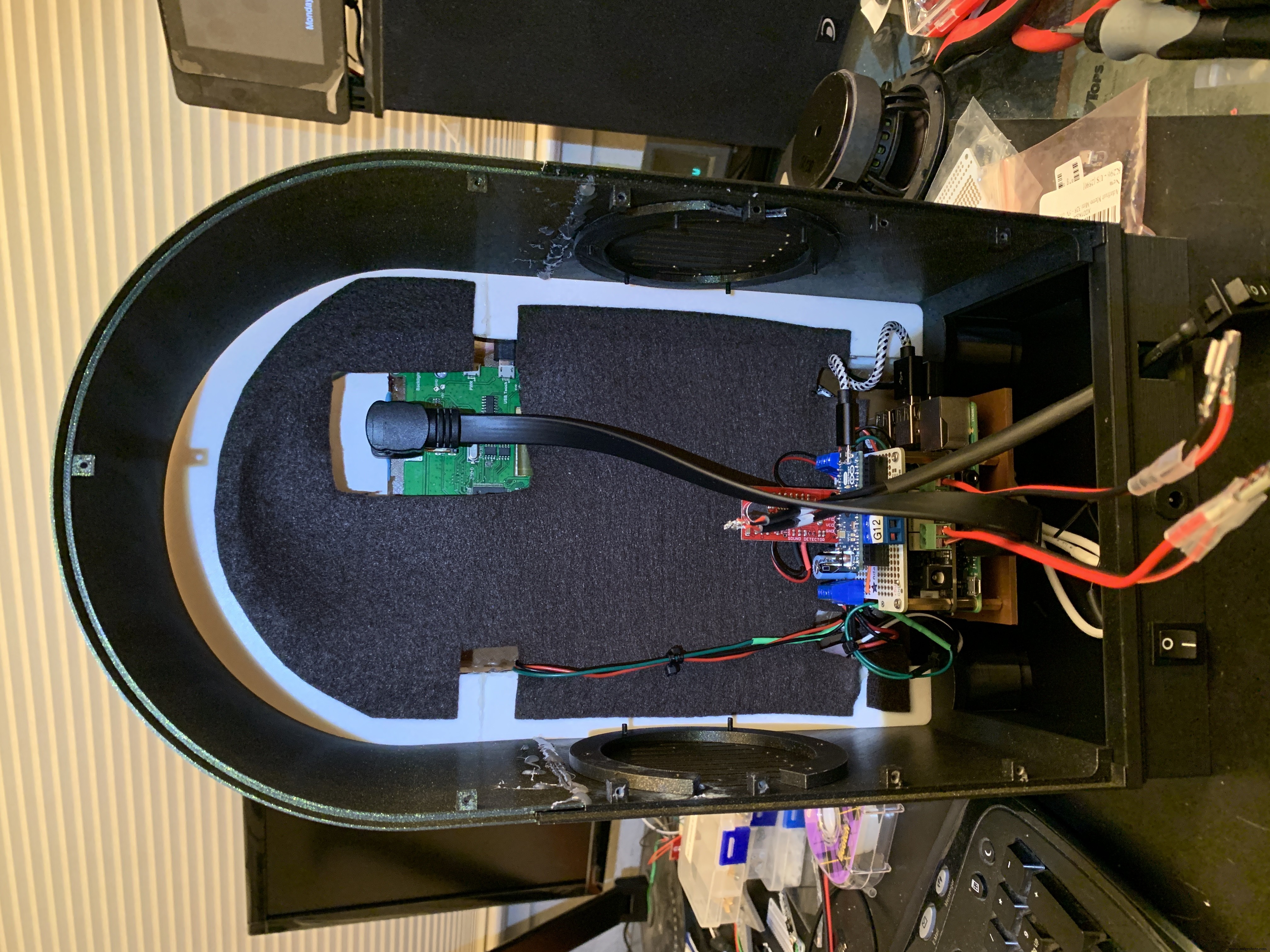
The parts are glued in starting from the inside, the Grille, and moving to the outside, the Neon Tubes, as shown in the video below.
Pause after gluing the Neon Tubes and mount the following hardware. This will give you more space to work in, before you glue in the back case. Refer to the Assembly Gallery photos below for details.
<울>Then continue gluing the Case and Base to the other assembled parts.
After the case is fully assembled and glued together, mount the Speakers and add Decorations.
There is an optional two-piece 3D printed case cover that screws into the back of the case.
_k2oC39lKQk.jpeg?auto=compress%2Cformat&w=680&h=510&fit=max)
Mounting the Hardware
In the following, all the hardware mentioned is found in the "Things" section.
“Right” and “Left“ are your right and left as you face the front of the jukebox.
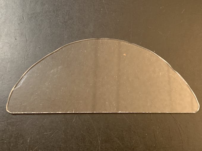
Acrylic Window and Photo
Use a rotary tool (eg., Dremel) at slow speed to cut a piece of clear acrylic. There is a template for this in the github download. Tape the template down on the acrylic and cut around the outside. Sand the edges and use CA to glue into the top of the Arch. Print a photo of your choice that will fill up the visible area and glue that in back of the acrylic.
NeoPixels
Glue the long LED strip edge-on to the Neon Tubes, so that the LEDs are facing inward to the Tubes. There is a small space between the LED and the edge of the strip that can help fit the string against the Neon Tubes. Align that to glue down.
The Grille Tube NeoPixels will be glued onto the Left and Right Bottom, with a "U" shape near the board mounting plate. Hold the strip down with pieces of tape and tack spots with hot glue. When those are solid, remove the tape and fill in the spots where the tape was with more glue.
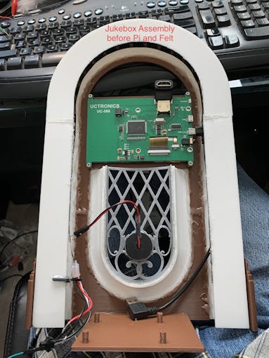
LCD Touch Screen
Screw the Touch Screen into the mounting posts at the top of the Arch, below the Acrylic window. The HDMI Touch Screen input is on the top of the screen. You need to insert a 90 degree to 270 degree HDMI adapter there, Plug the HDMI 1 ft. Male-to-Male flat cable into the adapter. The other end plugs into a Raspberry Pi 3. (If you're using a Raspberry Pi 4, you need a different cable that has a Micro HDMI in one end). Insert the Left-angle Micro USB to the Touch port on the LCD, and the USB-A end to a Raspberry Pi port. Thread this cable through the left Neon Tube.
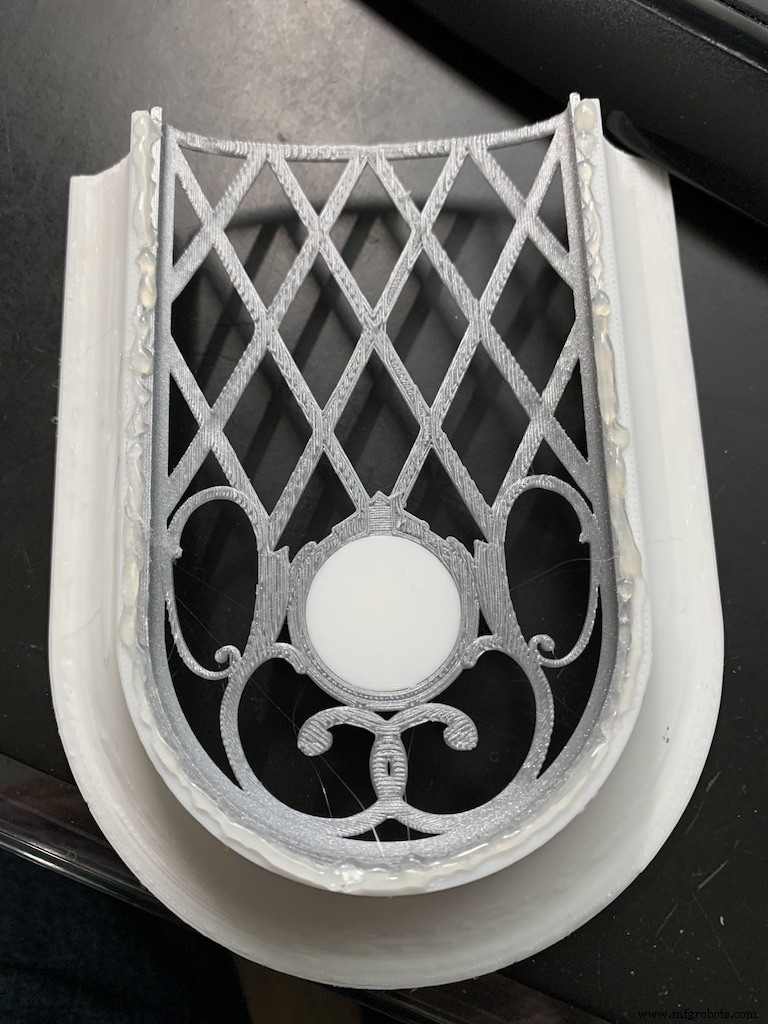
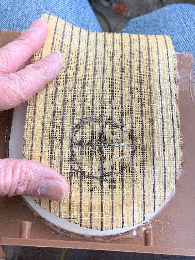
Grille Cloth and Star Light Holder
The Grille will be backed with "speaker cloth" to hide the inside of the jukebox. There will be an LED holder behind the Star Light to prevent light bleed, and a hole needs to be cut into the cloth for that.
Cut a piece of speaker cloth large enough to cover the Grille and the edges of the Grille tubes. Use the Star Light LED 3D printed holder as a guide and mark the speaker cloth in a circle for the outside of the holder. Mark a cross in the center of the circle Cut the two lines of the cross to make 4 sections. Cut the rounded part of each section to make a hole for the LED holder.
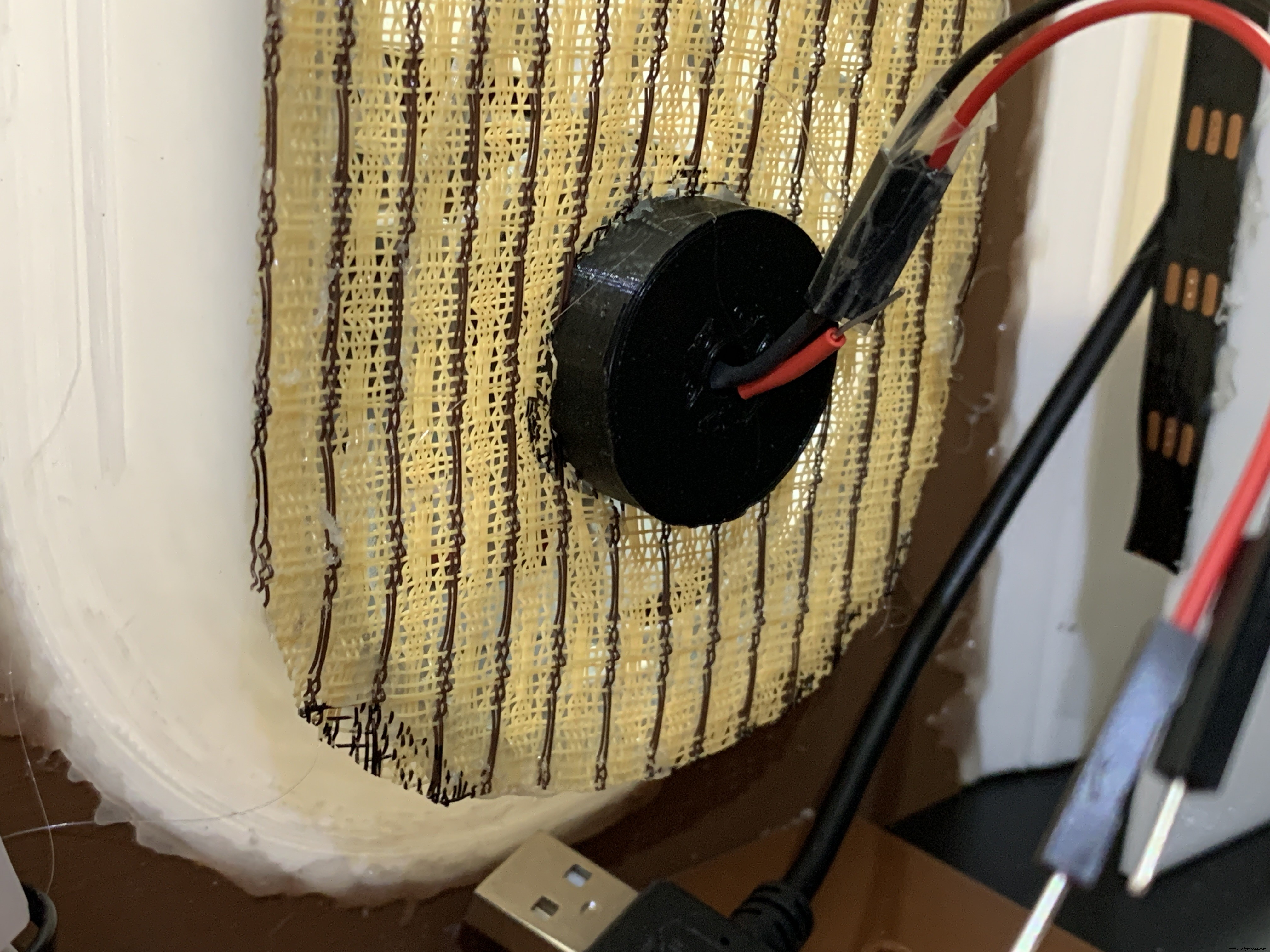
Mount the color-changing LED mentioned in the section Prepare the Circuit Board/Star Light, above. Insert the LED into the holder and glue it to the Star Light. CA will work well here.
With the LED holder glued in place, fit the speaker cloth over the holder and the Grille. Stretch and glue the edges of the cloth to the Grille Tubes.
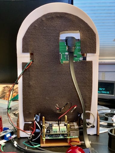
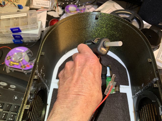
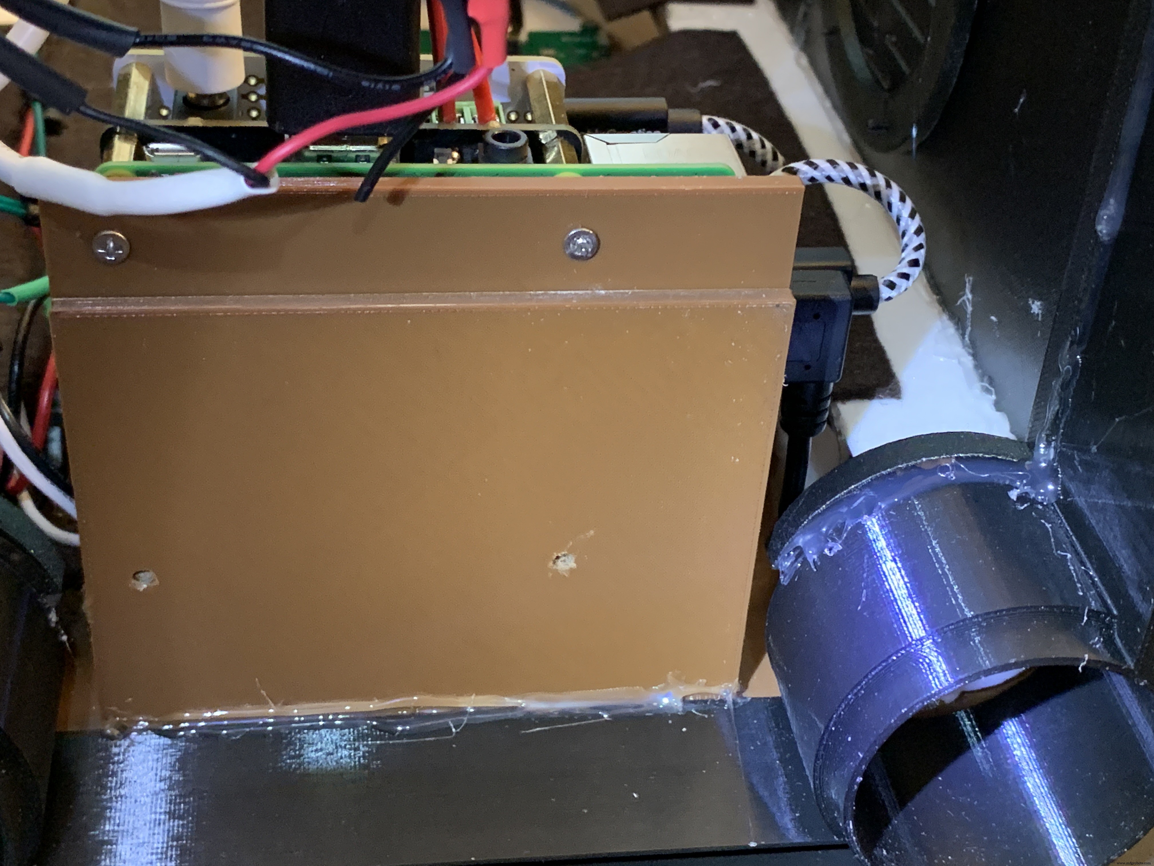
Raspberry Pi/IQAudio Pi Digi Amp/Arduino
Mount the Pi and other boards (you assembled and tested it in Getting Started, Right ?) onto the mounting plate with screws into the Pi's 5mm bottom standoffs. Plug the LCD HDMI and USB cables into the mounted Pi. There's an additional 6 inch Micro USB to Micro A cable. Plug the Micro end into the Arduino and the other end into the Pi to power the Arduino.
The Star Light +5V and GND plug into the power from the Digi Amp Plus +5V/GND rails.
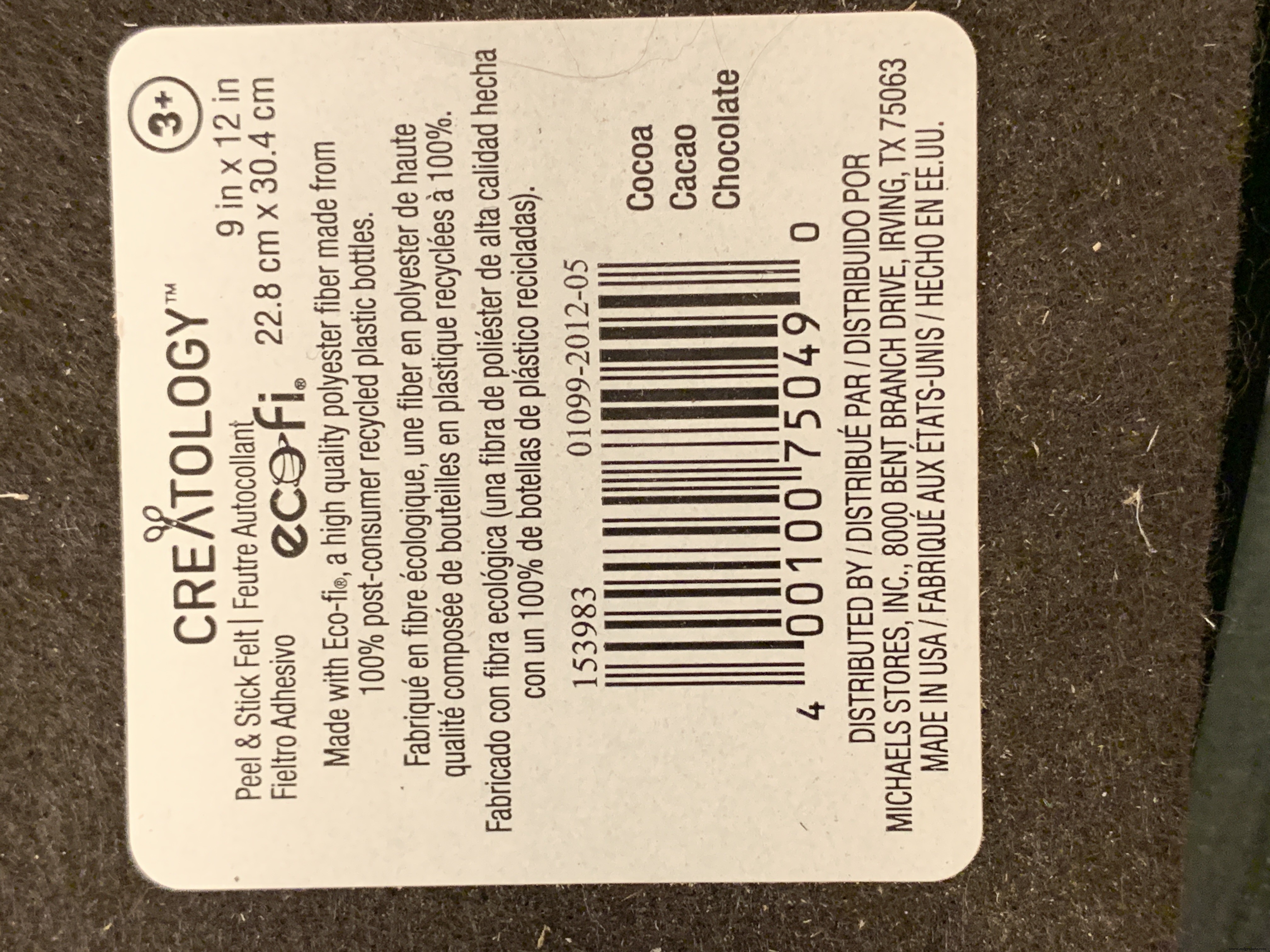
Adhesive Felt
To prevent light bleed, cover the inside with craft felt, which has its own adhesive backing Test fit the felt and cut holes to allow for cables and wires to pass through.
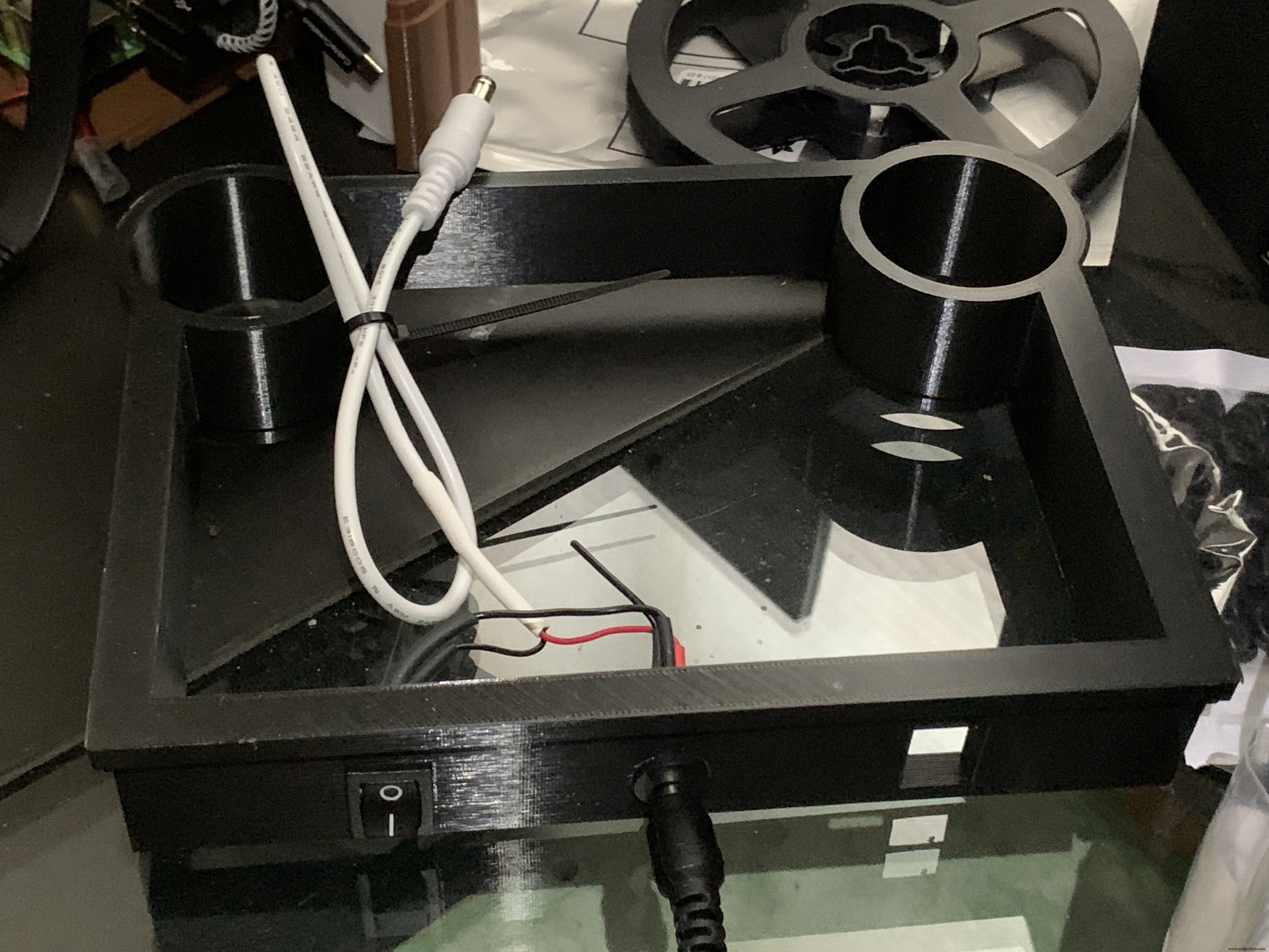
Base with Switches
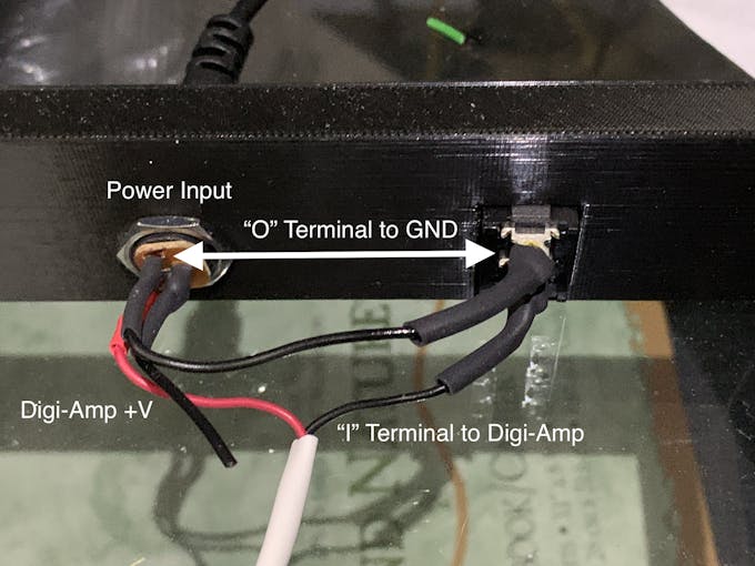
In addition to the Animation Selector Switch, there is an on-off rocker switch that is connected to a panel-mount jack.
Cut one GND (black) wire at least 80 mm long for this switch. Strip the insulating jacket off the power extension cable (white) in pictures about 80 mm long to expose a red and a black wire. Insert the barrel power connector and the on-off rocker switch into the base.
Solder the cut black wire to the terminal marked "O" on one end, the other end to the active GND pin on the barrel power connector. The other terminal "I" is soldered to the GND (black) of the power extension cable for the Digi Amp Plus Finally, the +V (red) of the power extension cable is soldered to the +V terminal of the barrel connector.
Plug the extension connector into the Pi Digi Amp Plus. Glue the Base onto the Bottom and Case.
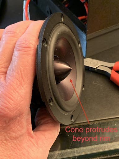
Speakers
The Dayton Audio RS100-8 speakers have a cone in the middle that prevents them from being mounted flush to a solid grille, as on this jukebox. If you're using these speakers (or some where the center protrudes), you'll have to use a mounting ring (3D file supplied) so the speakers can mount properly.
For the last step of assembly, screw the speakers in with 15 mm M2.5 metal screws and nuts.
Tip: To make assembly easier, mount the speaker rings to the case with the screws pushed in for alignment in the holes. Tack down with hot glue or CA glue. When solid, mount the speakers to the rings.
I had pretty good luck holding the tiny nuts down with my index finger and turning the screw to get the nuts started.
However, there is one screw hole straight back on each side that has very little clearance. It is hard to get the nut started on that screw. Putting blu-tack or tape on the nut may help position it to get it started.
Eventually, I did get all the nuts fastened.
Decorations
There are decorations on top and the two sides of the jukebox, with details in the github 3D Parts List document:
<울>Repeat for Left &Right:
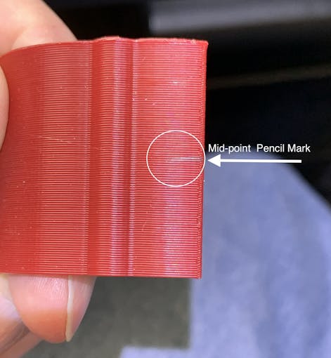
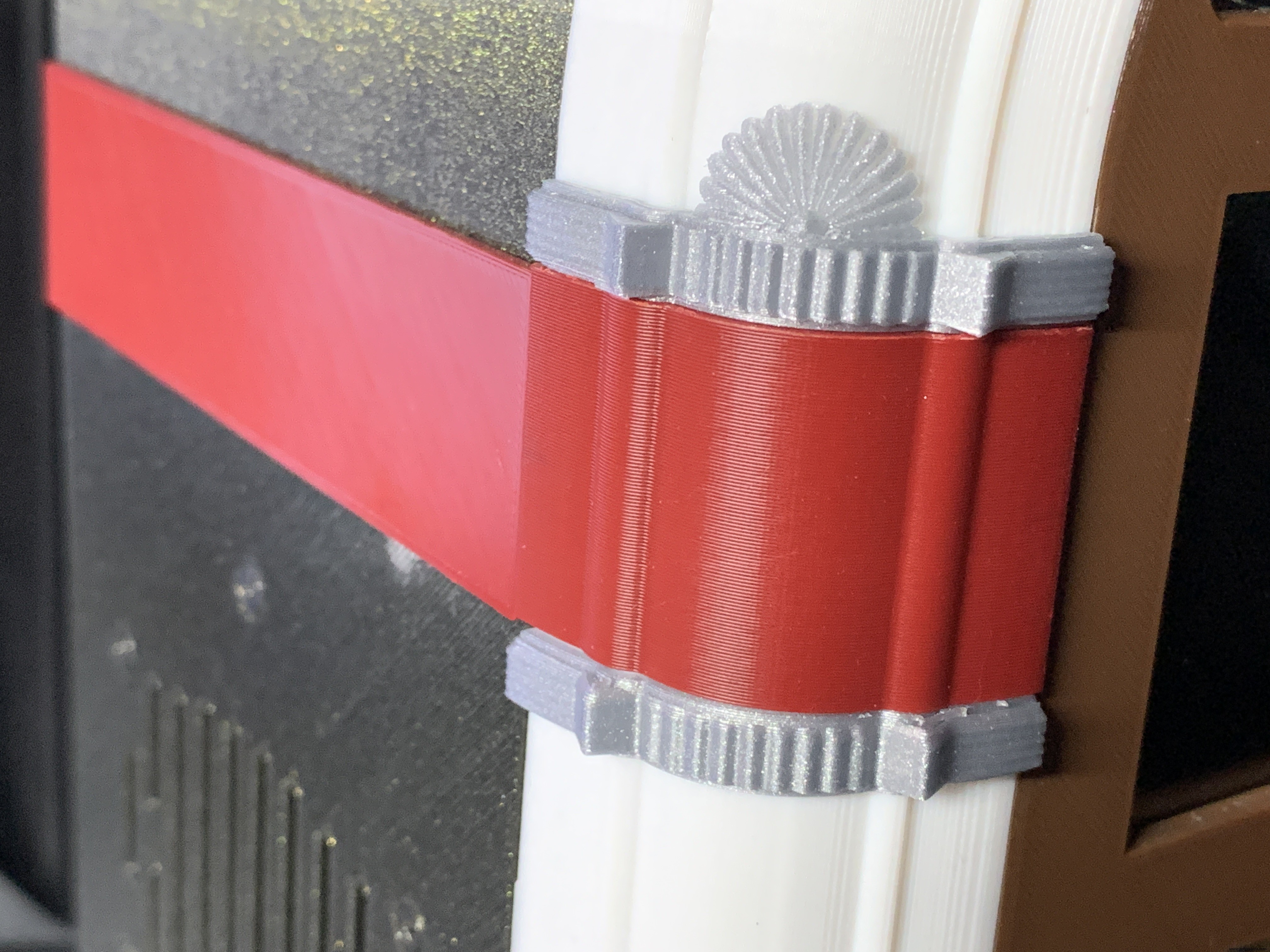
For the Neon Tubes, use a small ruler to mark the halfway point on the side of the Red Cover with a pencil. Then, match that to the Neon Tube joints and glue with CA.
The long Case Joint Cover aligns to the Neon Tube Red Cover and glues down to the case.
Gllue the Fan Decoration and Ornament at the top and bottom of the Red Cover
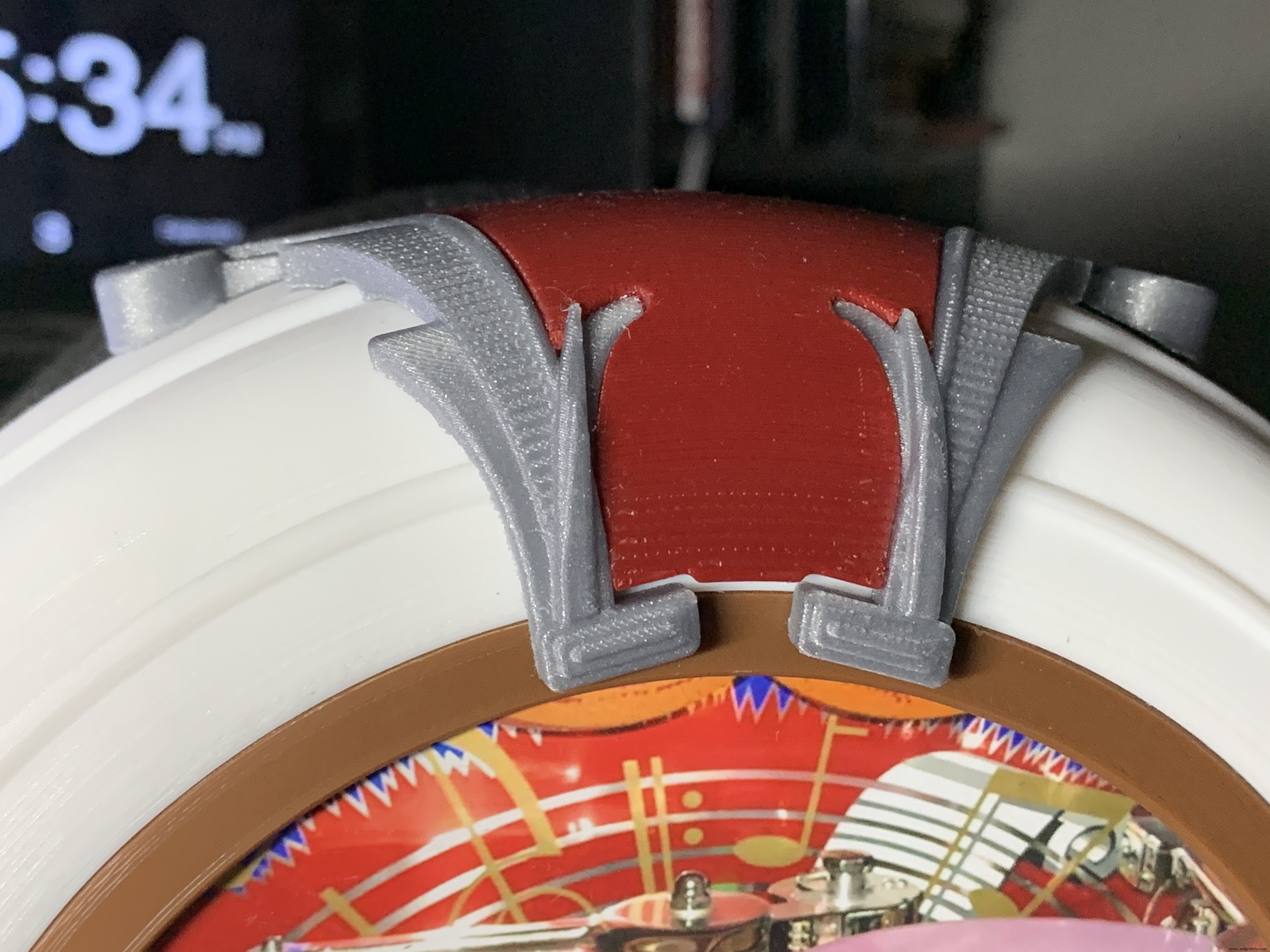
The Top Ornament (2 separate pieces) fits into the Top Red Ornament and is glued together as an assembly.
For alignment, make a pencil mark midway at the top of the Arch and another mark midway on the Top Red Cover. Align these two marks and glue.
Operation
Volumio has a fairly intuitive user interface that's easy to use.
To get started, press/select the 'Home' icon or the 'Browse' button from the 'Playback' window..You'll see something like the image below, depending on what options you have installed.
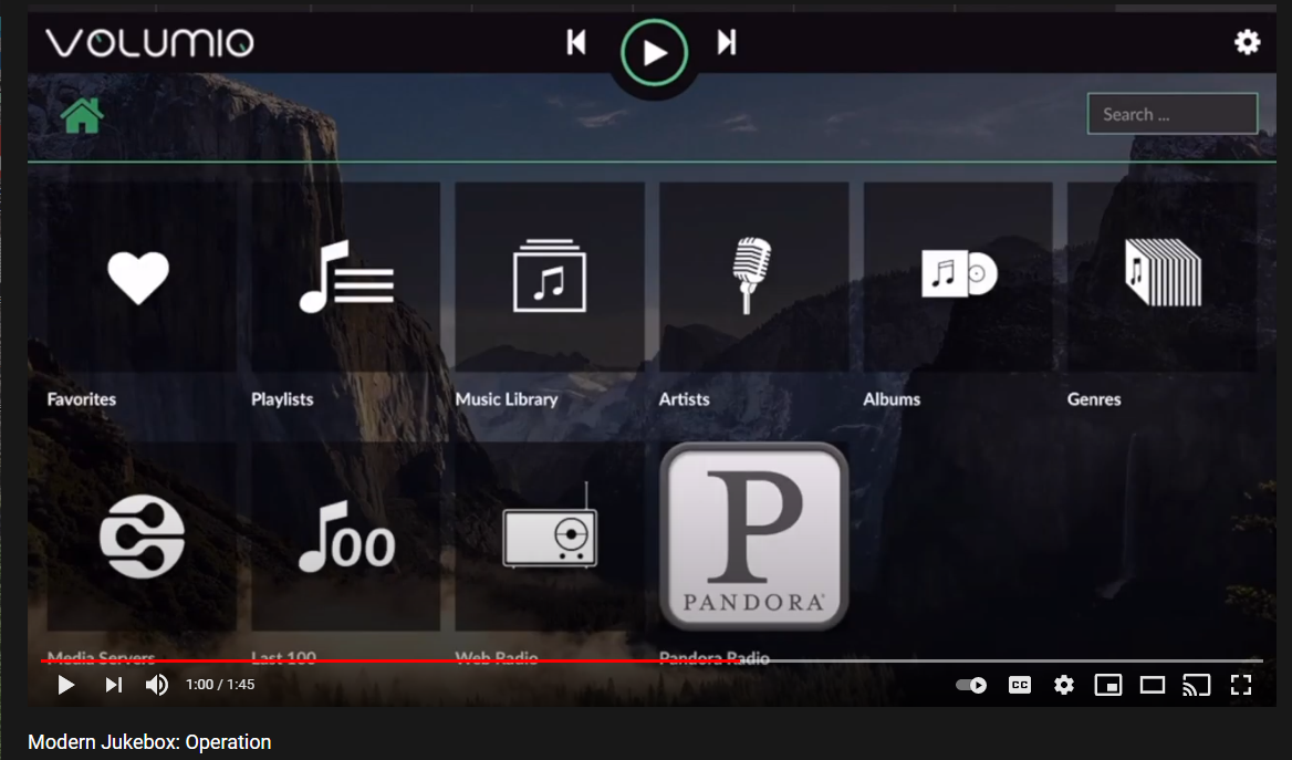
For Pandora and Spotify (paid subscription required), go to Settings/Plugins/Music Services. You can connect to Volumio from AirPlay with the Apple Music player.
Update September 20, 2021:
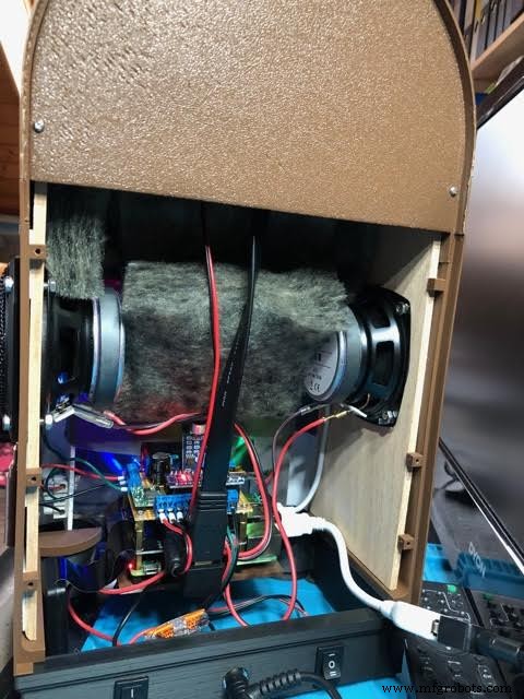
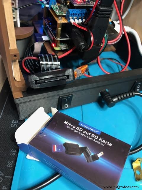
Raimund Trierscheid made a version of the Modern Jukebox, with improvements! Raimund added 5mm wood panels to the sides of the case to hold the heavy speakers and improve the sound.
Here are some photos:
제조공정
현대식 봉형 제품 압연기에서 철강 압연 긴 제품은 (i) 철근, (ii) 원형, 플랫, 사각형 및 육각형 등과 같은 모양의 철근 제품, (iii) 각(동일 및 이등), 채널과 같은 단면 제품의 일반적인 이름입니다. 보, 티 및 특수 프로파일 등 및 (iv) 선재. 긴 제품을 압연하는 밀은 긴 제품 밀로 알려져 있습니다. 압연되는 제품에 따라 이 압연기는 상업 봉강 압연기, 봉강 압연기, 경단면 압연기, 철근 압연기, 경상업 압연기, 특수 봉강 품질(SBQ) 압연기, 선재 압연기 등으로 불립니다. 이러한 압연기의 제품 범위는 일
현대식 고용량 고로의 주요 기능 일관제철소의 성능은 제철소의 성능에 크게 좌우됩니다. 일관제철소에서 용광로(BF)에서 용선(HM)을 생산하는 것은 전 세계적으로 제철 공정에서 선호되는 방식입니다. 철강 생산의 특정 비용은 BF에서 HM의 특정 비용에 크게 의존합니다. 따라서 BF는 철강 공장의 매우 중요한 단위입니다. 모던 BF는 실용용량이 큰 대용량 BF입니다. 그것은 많은 고급 기술 기능을 가지고 있습니다. 고급 기술 기능으로 인해 캠페인 수명이 길고 생산 지수가 향상되었습니다. 간접 환원 구역이 크고 비표면적이 작아 가스