

제조공정

산업 제조
 |
| × | 1 | |||
 |
| × | 1 |
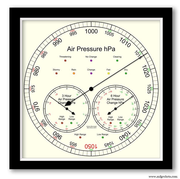
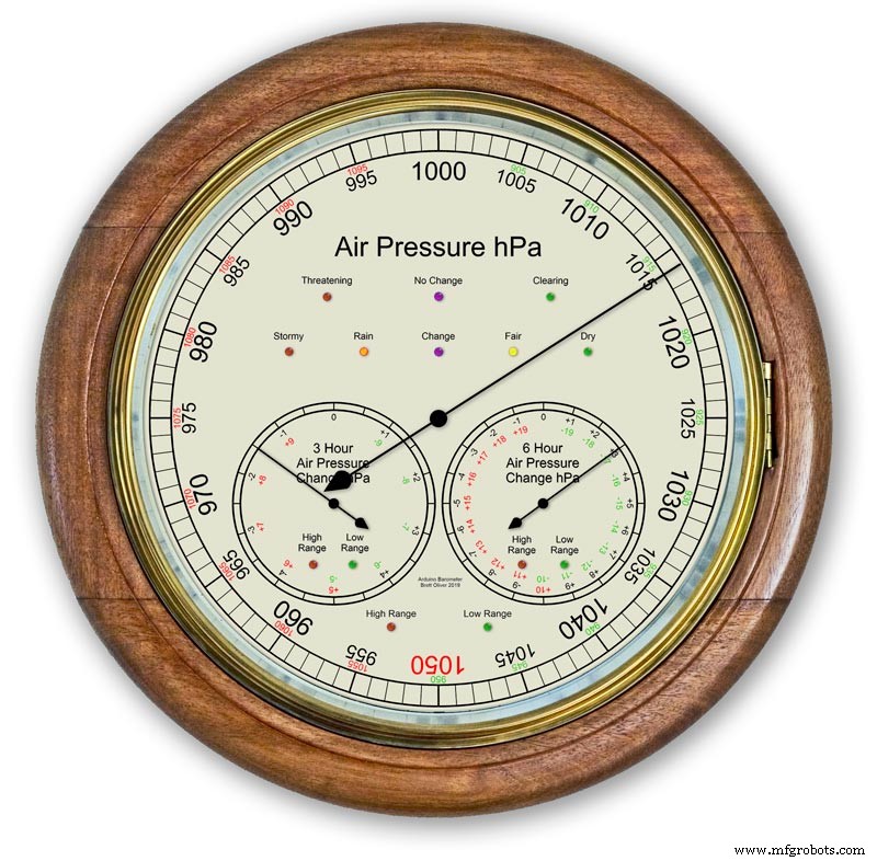
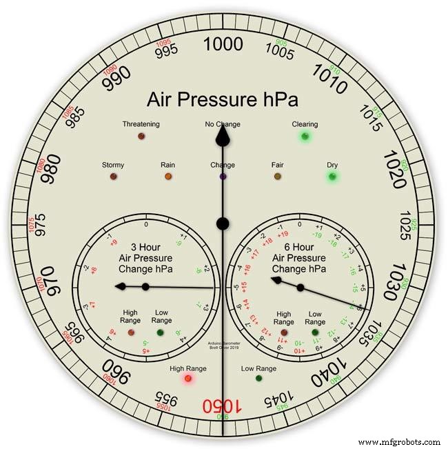
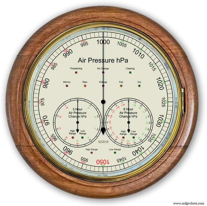
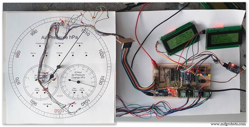
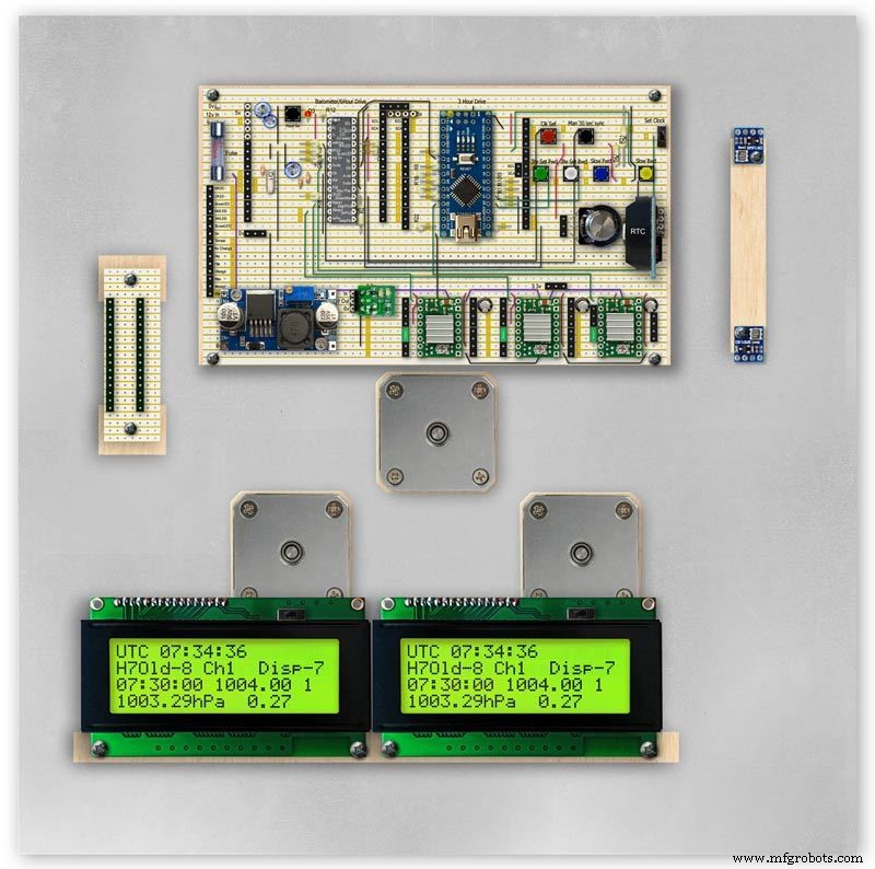
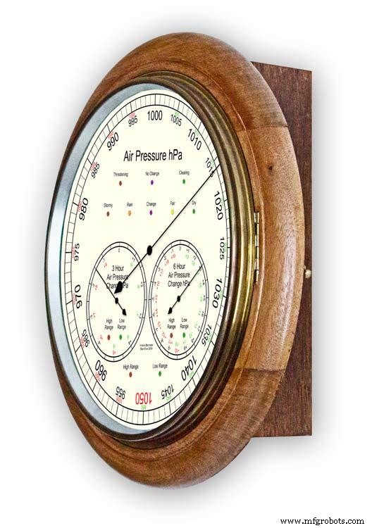
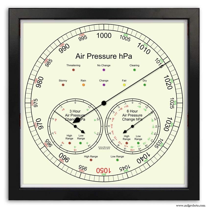
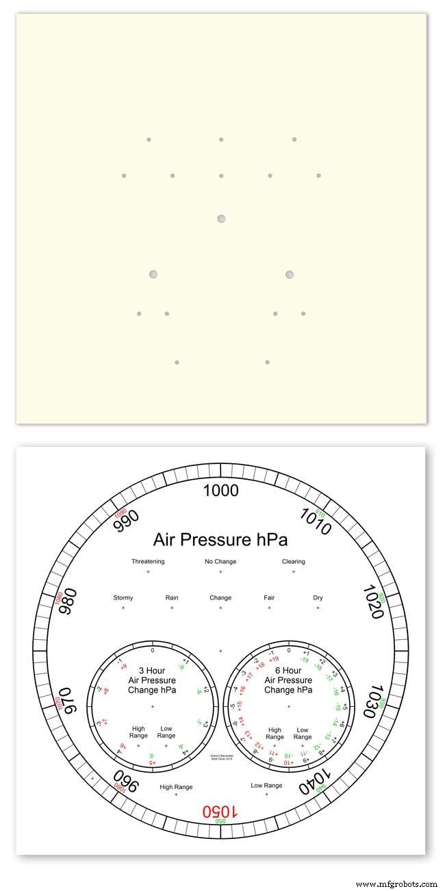
Arduino UNO 및 Nano를 사용하여 3개의 스테퍼 모터를 사용하여 12"(300m) 아날로그 디스플레이에 기압을 표시합니다.
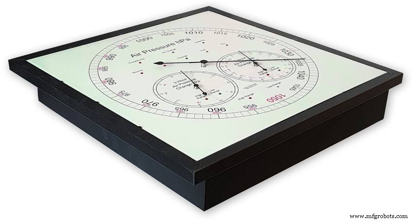
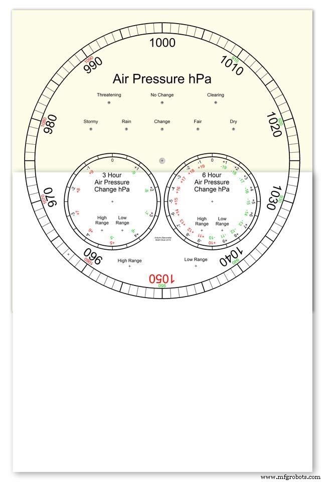
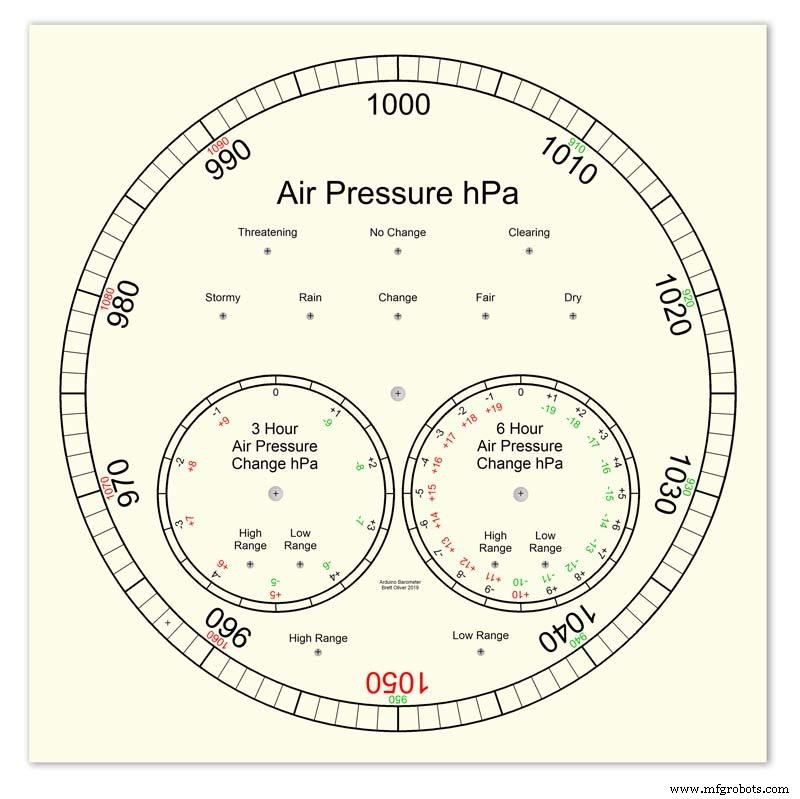
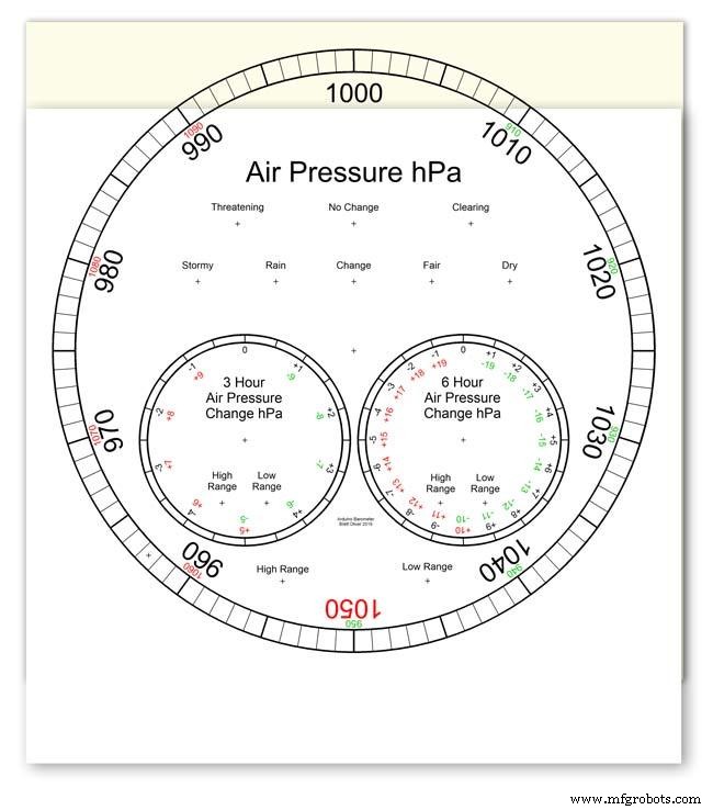
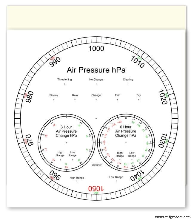
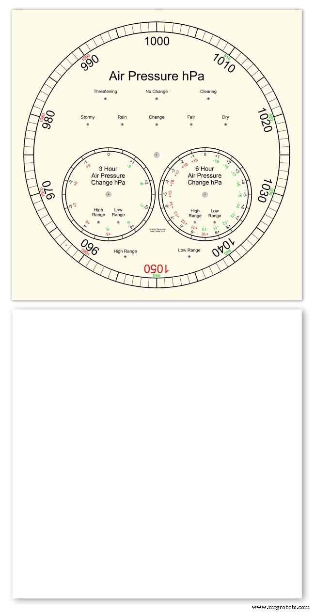
모던과 클래식 2가지 다이얼 디자인 중 선택이 가능합니다.
hPa(헥토파스칼) 단위의 기압은 큰 메인 다이얼에 표시되며 10분마다 업데이트됩니다.
2개의 보조 다이얼이 있습니다. 하나는 지난 6시간 동안의 압력 변화를 보여주고 다른 하나는 지난 3시간 동안의 압력 변화를 보여줍니다.
3시간 다이얼은 일기 예보에 사용되므로 0.5hPa의 해상도가 높아졌습니다. 3개의 디스플레이 모두에 확장 범위가 사용 중일 때 표시되는 LED와 3시간 디스플레이에서 일기 예보를 나타내는 LED가 있습니다.
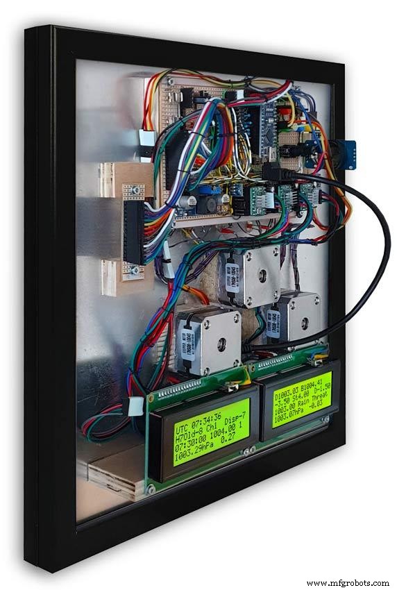
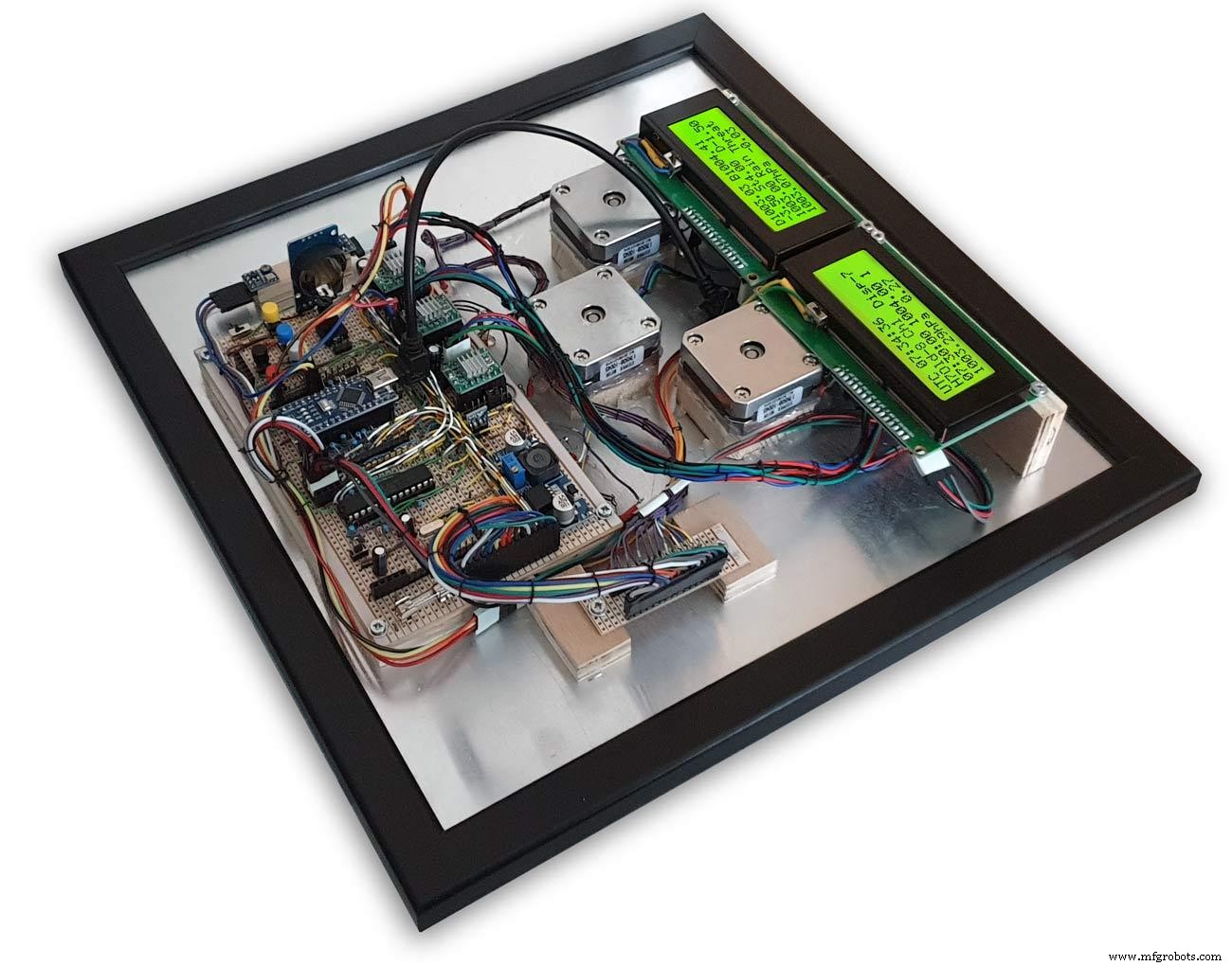
케이스 내부에는 2개의 20x4 LCD 화면이 각 마이크로프로세서의 정보를 표시합니다.
주 기압 표시와 6시간 표시는 RTC에 의해 제어됩니다. 이 시계는 또한 3시간 표시에 대해 1시간 펄스를 제공합니다.
1단계:기존 아날로그 기압계와 비교

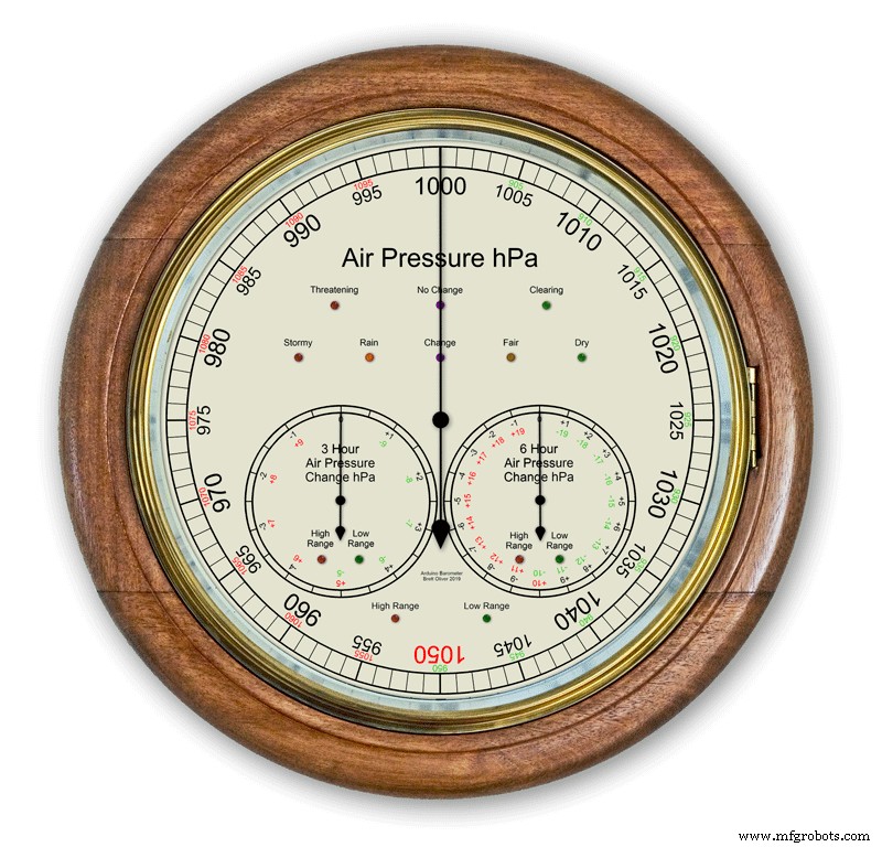
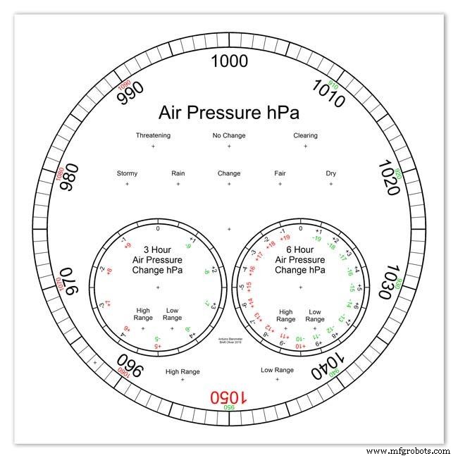
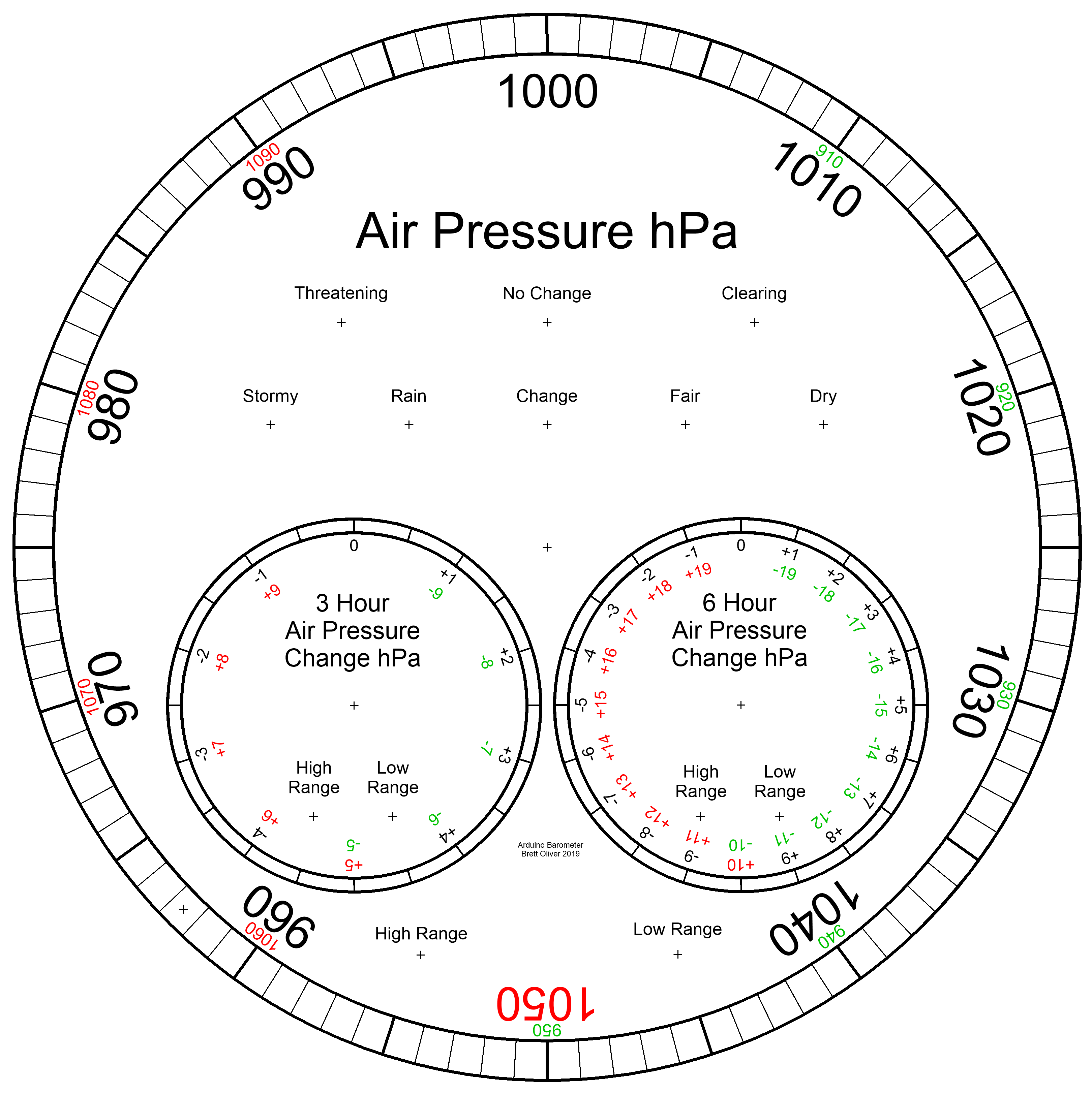
대부분의 아날로그 기압계 그림. 2 기압을 날씨를 예측하는 표시로 사용하면 이동식 포인터를 설정하고 기압 변화를 확인하기 위해 설정된 시간을 기억해야 합니다.
날씨는 단순히 다이얼 주위에 쓰여지고 포인터에서 읽혀집니다. 예측은 두 번째 포인터를 사용하고 3시간 동안의 변경 사항을 기록해야 하는 것보다 조금 더 복잡합니다. 현재 기압과 기압 상승/하강의 조합을 기억해야 예측을 얻을 수 있습니다.
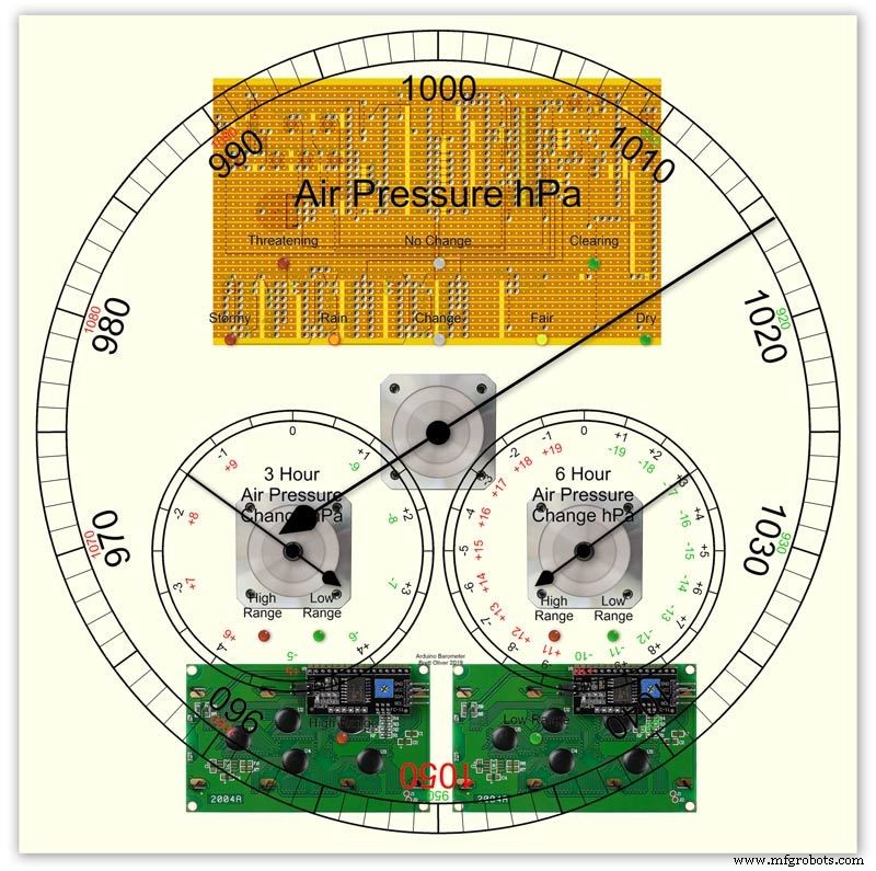
My Barometer는 3시간 및 6시간 동안 지속적으로 압력 변화를 모니터링하고 이러한 판독값을 2개의 별도 다이얼에 표시합니다.
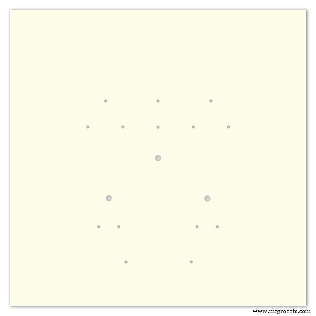
그림 1은 내 기압계의 일기 예보 범위를 보여줍니다.
pic.3은 날씨 예측 LED의 클로즈업을 보여줍니다. 날씨 예측은 지난 3시간 동안의 기압 변화를 기반으로 합니다.
2단계:폭풍을 예측하는 기압계 데모

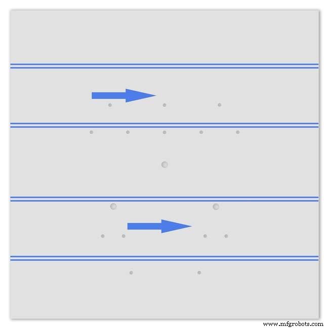
이 타임랩스 애니메이션은 기압계의 바늘과 예보 LED가 다가오는 폭풍에 어떻게 반응하는지 보여줍니다.
3단계:확장 범위 다이얼
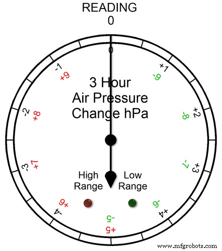

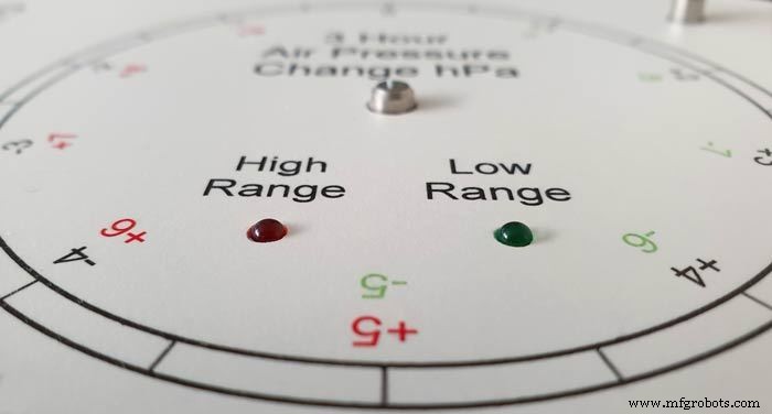
3개의 다이얼 모두 확장된 범위를 가지고 있습니다. 이렇게 하면 정상적인 날씨에 다이얼에 더 큰 해상도를 표시할 수 있습니다. 극한의 기상 조건에서는 다이얼이 확장 범위로 전환됩니다.
애니메이션 pic1. 확장된 범위가 작동 중일 때 LED가 어떻게 켜지는지 보여줍니다. 판독값이 +5 이상이면 빨간색 LED가 표시됩니다. 그런 다음 빨간색 눈금 글자를 읽습니다. 녹색 LED는 판독값이 -5 이하일 때 표시됩니다. 그런 다음 녹색 눈금 글자를 읽습니다. 판독값이 확장된 범위를 벗어나면(예:+9 또는 -9 위의 이 다이얼에서) 두 LED가 모두 켜져 이를 표시합니다. 다음 섹션을 참조하십시오.
확장된 범위에 대한 압력 판독값 그림 2 압력 판독값이 확장된 범위 + 또는 -를 초과하면 두 LED가 모두 켜져 극단적인 판독값이나 변화가 발생했음을 경고합니다. 다이얼은 실제로 여전히 판독값을 표시합니다. 예를 들어 판독값이 -10이면 두 LED가 모두 켜진 상태에서 다이얼이 0을 가리킬 것입니다. 3시간 판독값이 -11이면 두 LED가 모두 켜진 상태에서 다이얼이 -1을 가리킵니다. 읽기에 10을 더하면 됩니다.
아래 애니메이션에서는 3시간 기압차가 0에서 시작하여 기압차가 내려갑니다. -5 hPa에서 녹색 LED가 켜지면 음의 확장 범위가 사용 중임을 나타냅니다. 압력 변화는 -10hPa에 도달할 때까지 계속 떨어집니다. 이제 확장된 범위를 벗어났으므로 빨간색 LED도 켜집니다. 그런 다음 압력이 다시 -11hPa로 떨어지고 두 LED가 모두 켜진 상태를 유지합니다. 압력 변화는 -10hPa로 감소하기 시작하고 이것은 여전히 확장된 범위에 있으므로 두 LED가 모두 켜진 상태를 유지합니다. 압력 변화가 -10 미만으로 떨어지면 빨간색 LED가 꺼지고 확장된 범위가 다시 사용 중임을 표시합니다.
영국의 날씨를 확인한 후 다이얼에 확장 범위를 설정했고 3시간 및 6시간 확장 범위가 사용될 것으로 예상했지만 기본 기압계 디스플레이에서 확장 범위가 사용되지 않을 것이라고 생각했습니다.
그림 3 2020년 1월에 기압계를 프로토타이핑하는 동안 1050hPa의 기록적인 최고 판독값이 잉글랜드 남부입니다. 제 메인 기압계는 포인터가 빨간색 1050에 있고 빨간색 고범위 LED가 켜진 상태에서 확장 범위로 들어갔습니다.
4단계:LCD 정보 표시
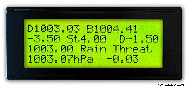
3시간
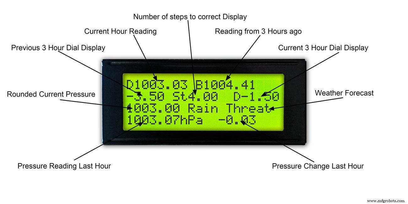
그림 1 &2 이 디스플레이는 3시간 측정값과 3시간 다이얼의 정보를 보여줍니다. 또한 현재 및 지난 3시간 동안 읽은 내용을 기반으로 일기 예보를 보여줍니다.
6시간
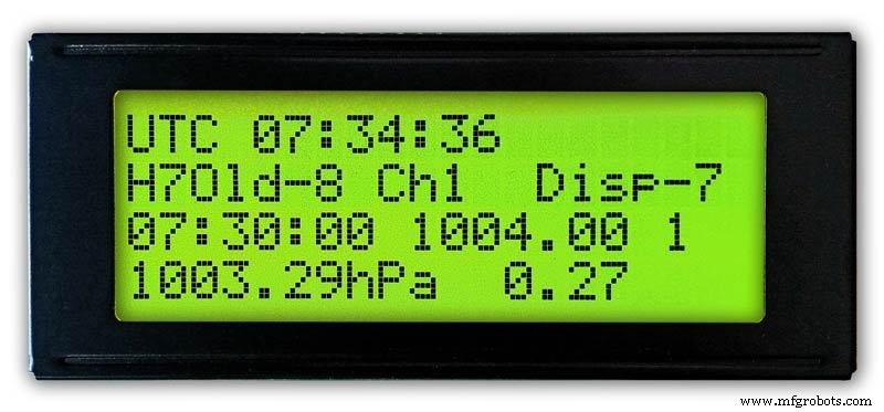
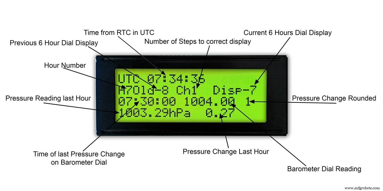
그림. 3 &4 이 디스플레이는 기본 기압계 다이얼 판독값과 6시간 판독값도 표시합니다.
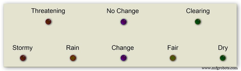
5단계:날씨 예측

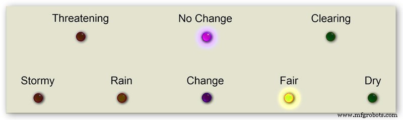


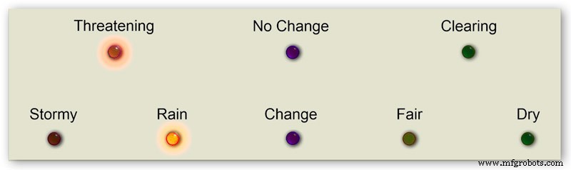
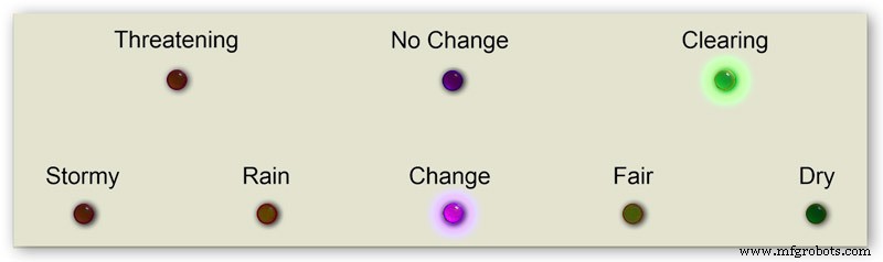
내 기압계의 일기 예보는 8개의 LED를 사용합니다.
현재 기압과 지난 3시간 동안의 변화율을 사용하여 LED에서 날씨를 예측합니다.
애니메이션 1은 예측 LED 조합의 다양한 조합을 보여줍니다.
여러 기상 사이트를 방문하여 기압계로 날씨를 예측하는 방법에 대해 다음과 같은 정보를 수집했습니다.
기압계로 날씨 예측하기
보다 구체적으로, hPa 단위로 표시되는 기압계는 다음과 같이 해석할 수 있습니다.
측정값이 1022hPa를 초과하는 경우
기압이 오르거나 일정하면 맑은 날씨가 계속된다는 뜻입니다.기압이 천천히 떨어지면 맑은 날씨가 납니다.기압이 급격히 떨어지면 흐리고 따뜻한 상태가 됩니다.
1009–1022hPa 사이인 경우
기압이 오르거나 일정하면 현재 상태가 계속될 것임을 의미합니다.기압이 천천히 떨어지는 것은 날씨의 변화가 거의 없음을 의미합니다.기압이 급격히 떨어지면 비가 올 가능성이 있고, 충분히 추울 경우 눈이 내릴 가능성이 있음을 의미합니다.
판독값이 1009hPa 미만인 경우
기압이 오르거나 안정되면 날씨가 맑아지고 선선함을 나타냅니다. 기압이 천천히 떨어지면 비가 온다는 뜻입니다. 기압이 급격히 떨어지면 폭풍이 오고 있음을 나타냅니다.
내 기압계 위의 정보를 사용하여 다음 논리를 적용하여 날씨를 예측합니다.
결과 LED가 켜진 상태에서 아래 순서대로 논리가 적용됩니다.
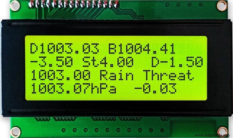
그림 2 기압 <1009 hPa
기압이 오르거나 안정되면 맑아지고 선선한 날씨를 나타냅니다.
기압 <1009.00 및 3시간 변화>=0
그림 3 기압 <1009 hPa
천천히 떨어지는 기압은 비를 나타냅니다.
기압 <1009.00 및 3시간 변화 <0 및 3시간 변화>=-1.5
그림 4 기압 <1009 hPa
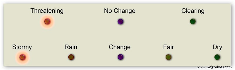
급격하게 떨어지는 기압은 폭풍이 오고 있음을 나타냅니다.
기압 <1009.00 및 3시간 변화 <-1.5
그림 5 기압은 1009~1022hPa입니다.
압력이 오르거나 안정되면 현재 상태가 계속될 것입니다.
기압이 천천히 떨어진다는 것은 날씨의 변화가 거의 없다는 것을 의미합니다.
기압>=1009.00 및 기압 <=1022.00 및 3시간 변경>=-1.5 및 3시간 변경 <=1.5
그림 6 기압은 1009~1022hPa입니다.
기압이 급격히 상승하면 날씨가 맑아지고 있음을 의미합니다.
기압>=1009.00 및 기압 <=1022.00 및 3시간 변화> 1.5
그림 7 기압은 1009~1022hPa입니다.
급격하게 떨어지는 기압은 비가 올 가능성이 있고, 충분히 추우면 눈이 올 가능성이 있음을 의미합니다.
기압>=1009.00 및 기압 <=1022.00 및 3시간 변화 <-1.5
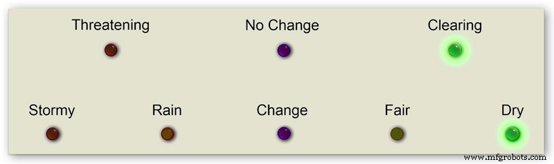
그림 8 1022 hPa 이상의 기압
기압이 오르거나 안정되면 건조한 날씨를 의미합니다.
기압> 1022.00 및 3시간 변화>=0
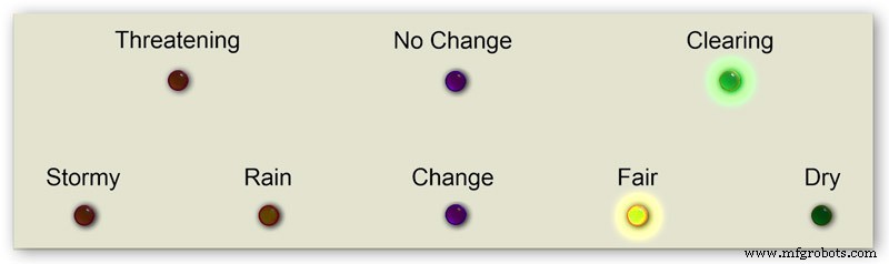
그림 9 1022 hPa 이상의 기압
기압이 서서히 낮아지는 것은 날씨가 맑음을 의미합니다.
기압> 1022.00 및 3시간 변화 <0 및 3시간 변화>=-1.5
그림 10 1022 hPa 이상의 기압
급격히 떨어지는 압력은 변화를 의미합니다.
기압> 1022.00 &&3시간 변화 <-1.5
6단계:기압계 시작
초기 전원을 켜면 LED 테스트가 수행됩니다.
완료되면 바늘이 보정 준비가 된 초기 설정으로 이동합니다.
7단계:초기 시작 설정 RTC
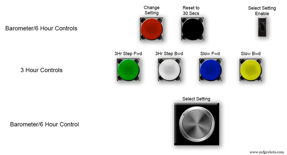


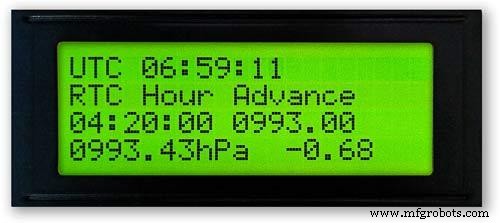
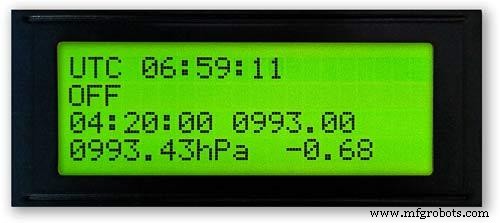
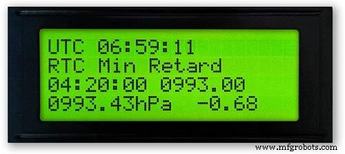

그림 1 초기 전원을 켤 때 Vero Board의 컨트롤을 사용하여 기압계를 설정해야 합니다.
RTC
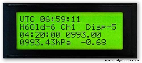
그림 2 RTC는 정확한 시간으로 설정해야 합니다. 저는 UTC로 설정하고 서머 타임으로 변경하는 것을 귀찮게 하지 않습니다. 시간을 조정하기 전에 이 경우 -5의 "Disp" 값을 기록해 두십시오. 이것은 6시침의 값이며 나중에 설정에 필요합니다. "설정 활성화 선택" 스위치를 켜기 위치로 밉니다. 디스플레이는 변경되지 않습니다.
Pic.3 "Select Setting" Knob를 시계 방향으로 천천히 돌리면 메인 LCD 디스플레이의 2번째 행이 변경됩니다.
디스플레이에 "RTC Hour Retard"가 표시되면 중지하십시오. RTC 시간을 늦추려면 빨간색 "변경 설정" 버튼을 누르십시오. 클릭 한 번으로 시간을 뒤로 이동합니다. 여러 번 클릭하면 누른 클릭 수만큼 뒤로 이동하지만 RTC를 업데이트하는 데 1초가 걸립니다.
그림 4 "설정 선택" 노브를 더 돌리면 디스플레이가 "RTC Hour Advance"로 변경됩니다.
RTC 시간을 앞당기려면 빨간색 "설정 변경" 버튼을 누르십시오. 클릭 한 번으로 몇 시간 앞으로 나아갈 수 있습니다. 여러 번 클릭하면 누른 클릭 수만큼 앞으로 이동하지만 RTC를 업데이트하는 데 1초가 걸립니다.
그림 5 "설정 선택" 노브를 더 돌리면 디스플레이가 "RTC Min Retard"로 변경됩니다.
RTC 분을 지연시키려면 빨간색 "설정 변경" 버튼을 누르십시오. 한 번 클릭하면 분을 뒤로 이동합니다. 여러 번 클릭하면 누른 클릭 수만큼 뒤로 이동하지만 RTC를 업데이트하는 데 1초가 걸립니다.
그림 6 "설정 선택" 노브를 더 돌리면 디스플레이가 "RTC Min Advance"로 변경됩니다.
RTC 분을 진행하려면 빨간색 "설정 변경" 버튼을 누르십시오. 클릭 한 번으로 분 앞으로 이동합니다. 여러 번 클릭하면 누른 클릭 수만큼 앞으로 이동하지만 RTC를 업데이트하는 데 1초가 걸립니다.
그림 7 RTC 설정 또는 기타 설정이 완료되면 디스플레이에 "Off"가 표시될 때까지 "Select Setting" 노브를 시계 반대 방향으로 완전히 돌리십시오.
"설정 활성화 선택" 스위치를 끄기 위치로 밉니다.
메모. 검은색 "30초로 재설정" 버튼을 눌러 언제든지 초를 30초로 동기화할 수 있습니다. 이제 전원이 꺼지면 RTC에 시간이 기억됩니다.
8단계:초기 시작 설정 6시침


6시침 설정
그림1 RTC가 설정되면 기압계와 6시간 기압 바늘을 설정해야 합니다.
"설정 활성화 선택" 스위치를 켜기 위치로 밉니다. 디스플레이는 변경되지 않습니다.
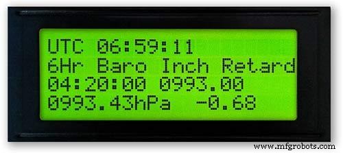
"6Hr Baro Inch Retard"가 표시될 때까지 "Select Setting" 노브를 시계 방향으로 천천히 돌립니다.
처음 전원을 켤 때 6시간 바늘은 가장 가까운 숫자로 보정해야 합니다.
가장 가까운 숫자가 손 뒤에 있으면 빨간색 "설정 변경" 버튼을 누릅니다. 한 번의 클릭으로 손을 한 걸음씩 뒤로 밉니다. 버튼을 누르고 있으면 손이 반복적으로 뒤로 젖혀집니다. 손이 정확히 숫자 위에 있으면 버튼에서 손을 뗍니다.
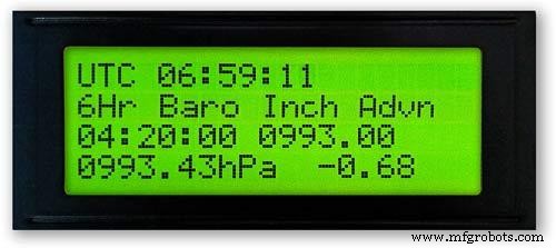
그림 2 손 앞에 가장 가까운 숫자가 있거나 위의 방법을 사용하여 손이 인치 지연된 경우 "6Hr Baro Inch Advn"이 표시될 때까지 "Select Setting" 노브를 시계 방향으로 돌립니다.
빨간색 "설정 변경" 버튼을 누릅니다. 한 번의 클릭으로 손이 한 걸음씩 앞으로 나아가게 됩니다. 버튼을 누르고 있으면 손이 반복적으로 앞으로 뻗습니다. 손이 정확히 숫자 위에 있으면 버튼에서 손을 뗍니다.
그림 3 6시침이 숫자에 정확히 맞춰졌다면 시침을 정확한 값으로 설정해야 합니다.
RTC를 조정하기 전에 이 숫자 -5를 기록해 두었습니다.
그림 4 6시간 표시 바늘이 너무 앞선 경우.
"6Hr Baro Retard"가 표시될 때까지 "Select Setting" 노브를 시계 방향으로 돌립니다. 빨간색 "설정 변경" 버튼을 눌렀다 놓습니다. 이 실은 6시간 바늘을 1단위 뒤로 이동합니다. 6시 바늘이 기록된 숫자에 도달하면 멈춥니다.
그림 5 6시간 표시 바늘이 느린 경우.
"6Hr Baro Advance"가 표시될 때까지 "Select Setting" 노브를 시계 방향으로 돌립니다. 빨간색 "설정 변경" 버튼을 눌렀다 놓습니다. 이 실 단계는 6시간 바늘이 1단위 전체를 앞으로 나아가게 합니다. 6시 바늘이 기록된 숫자에 도달하면 멈춥니다.
그림 6 6시간 표시는 해당 기간 동안 메모리에 판독값을 저장해야 하므로 올바르게 표시하려면 8시간이 걸립니다.
로드하기 전에 항상 이전 기압 판독값을 코드에 추가할 수 있습니다. 시작부터 작동하려면 6시간 표시가 필요합니다.
코드는 H =6 위에 표시된 대로 시간을 H 숫자로 변환합니다. 코드 라인 128에서 H6은 현재 시간 판독값을 hour6 아래에 두는 것을 의미합니다. 이전 판독값은 hour7의 이전 판독값입니다.
정수 시간0 =1015;
정수 시간1 =1016
;int hour2 =1015;
정수 시간3 =1016;
정수 시간4 =1016
;int 시간5 =1016;
정수 시간6 =1012;
정수 시간7 =1013;
인터넷에서 지역 판독값을 얻을 수 있어야 합니다.
기압계를 구성하는 동안 이를 확인할 수 있도록 기상 관측소에서 페이지를 설정했습니다.
Kenley Surrey UK의 시간별 변경 사항을 보려면 이 링크를 클릭하십시오.
9단계:초기 시작 설정 주 기압계 바늘


주 기압계 바늘 설정
그림 1 이제 6시간 표시가 정확합니다. 주 기압계 바늘은 주 LCD의 3번째 줄 아래에 있는 둥근 해수면 기압으로 설정해야 합니다.
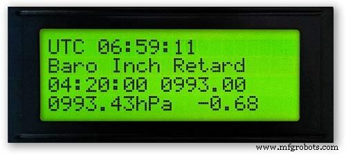
처음 전원을 켤 때 주 기압계 바늘은 가장 가까운 숫자로 보정해야 합니다. "Baro Inch Retard"가 표시될 때까지 "Select Setting" 노브를 시계 방향으로 돌립니다.
가장 가까운 숫자가 손 뒤에 있으면 빨간색 "설정 변경" 버튼을 누릅니다. 한 번의 클릭으로 손을 한 걸음씩 뒤로 밉니다. 버튼을 누르고 있으면 손이 반복적으로 뒤로 젖혀집니다. 손이 정확히 숫자 위에 있으면 버튼에서 손을 뗍니다.
그림 2 가장 가까운 숫자가 손 앞에 있거나 위의 방법을 사용하여 손이 인치 지연된 경우 "Baro Inch Advn"이 표시될 때까지 "Select Setting" 노브를 시계 방향으로 돌립니다.
빨간색 "설정 변경" 버튼을 누릅니다.
한 번의 클릭으로 손이 한 걸음씩 앞으로 나아가게 됩니다. 버튼을 누르고 있으면 반복적으로 손이 앞으로 조금씩 움직입니다. 손이 정확히 숫자 위에 있으면 버튼에서 손을 뗍니다.
Pic.3 기압계의 주 바늘이 너무 앞서 있는 경우.
"기압계 지연"이 표시될 때까지 "설정 선택" 노브를 시계 방향으로 돌립니다.
빨간색 "설정 변경" 버튼을 눌렀다 놓습니다.
이렇게 하면 주 기압계 바늘이 1단위 뒤로 이동합니다. 시침이 표시된 둥근 해수면 기압에 도달하면 멈춥니다.
그림 4 주 기압계 바늘이 표시된 둥근 해수면 기압에 비해 느린 경우.
"Barometer Advance"가 표시될 때까지 "Select Setting" 노브를 시계 방향으로 돌립니다.
빨간색 "설정 변경" 버튼을 눌렀다 놓습니다.
이렇게 하면 주 기압계 바늘이 전체 단위 1만큼 앞으로 이동합니다. 바늘이 표시된 둥근 해수면 압력에 도달하면 멈춥니다.
10단계:초기 시작 설정 3시간침


3시침 설정.
Oic.1 3시 바늘의 조정은 Vero 보드의 녹색, 흰색, 파란색 및 노란색 4개 버튼으로 이루어집니다.
처음 전원을 켤 때 3시간 바늘을 가장 가까운 단위 또는 1/2 단위로 보정해야 합니다.
그림 2 3시침에 가장 가까운 단위 값이 3시침보다 앞선 경우 노란색 "Slow Bwd" 버튼을 눌러 바늘을 뒤로 인치하십시오. 버튼을 계속 누르고 있으면 손이 뒤로 젖혀집니다.
3시간 바늘에 가장 가까운 단위 값이 3시간 바늘 뒤에 있는 경우 파란색 "Slow Fwd" 버튼을 눌러 바늘을 앞으로 인치십시오. 버튼을 계속 누르고 있으면 손이 앞으로 조금씩 움직입니다.
3시간 바늘이 정확히 단위/반 단위에 있으면 바늘을 3시간 LCD 디스플레이에서 값 "D"로 설정할 수 있습니다.
바늘이 값 "D"보다 앞서 있으면 흰색 "3Hr Step Bwd" 버튼을 눌러 3시간 바늘을 반 단위 뒤로 이동합니다.
바늘이 값 "D"보다 작은 경우 녹색 "3Hr Step Fwd" 버튼을 눌러 3시간 바늘을 반 단위 앞으로 이동합니다.
3시간 표시는 해당 기간 동안 메모리에 판독값을 저장해야 하므로 올바르게 표시하려면 4시간이 걸립니다.
로드하기 전에 항상 이전 기압 판독값을 코드에 추가할 수 있습니다. 시작부터 작동하려면 예보 및 3시간 표시가 필요합니다.
124행의 3시간 표시 코드
float hour0은 현재 시간입니다.
float hour1은 이전 시간 등입니다.
float hour0 =1036.00;
부동 시간1 =1036.00;
float hour2 =1036.00;
float hour3 =1036.00;
float hour4 =1036.00;
인터넷에서 지역 판독값을 얻을 수 있어야 합니다.
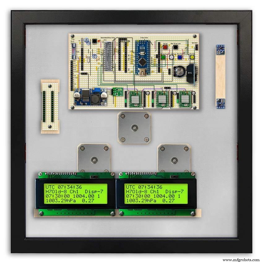
11단계:모듈/구성요소

모듈
가능한 경우 이 프로젝트는 사전 제작된 모듈을 사용하여 건설 및 설계 시간을 절약합니다.
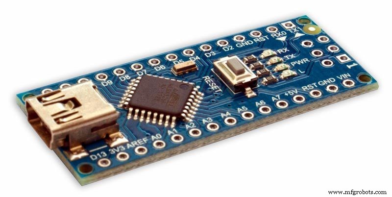
마이크로프로세서
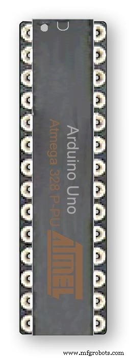
이 프로젝트는 Atmega 328(UNO) pic.1과 Arduino Nano pic.2의 2개의 마이크로프로세서를 사용합니다. 다른 프로젝트에서 이미 328을 구축했고 Vero 보드의 제한된 공간으로 인해 Nano도 추가했기 때문에 이 조합을 사용했습니다.
힘
기압계는 약 65mA를 사용하며 각 모터가 10분 ~ 1시간마다 몇 분의 1초씩 걸을 때마다 약간 증가합니다.
AMS117 pic.3
이 프로젝트의 모듈은 3.3v이며 BMP180 모듈에 전원을 공급하는 데 사용됩니다.
AMS1117 시리즈 조정 가능 및 고정 전압 조정기는 최대 1A 출력 전류를 제공하고 1V 입력-출력 차동으로 작동하도록 설계되었습니다. 장치의 드롭아웃 전압은 최대 1.3V를 보장하며 더 낮은 부하 전류에서 감소합니다. 온칩 트리밍은 기준 전압을 1.5%로 조정합니다. 전류 제한은 레귤레이터와 전원 회로 모두의 과부하 조건에서 스트레스를 최소화하도록 설정됩니다. 이 프로젝트의 모듈은 3.3v이며 BMP180 모듈에 전원을 공급하는 데 사용됩니다.
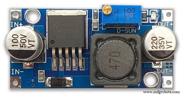
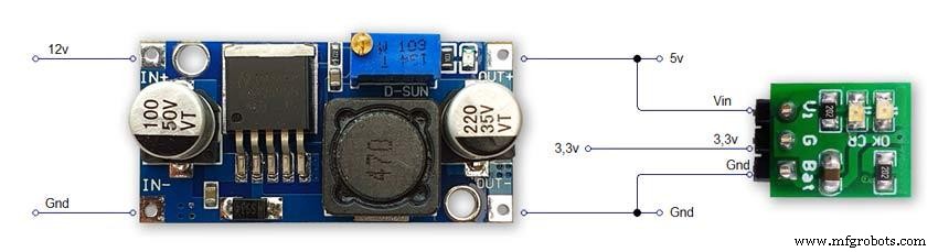
LM2596 벅 DC-DC 변환기 3.0-40V ~ 1.5-35V pic.4이 모듈은 12v 입력을 5v로 변환합니다.
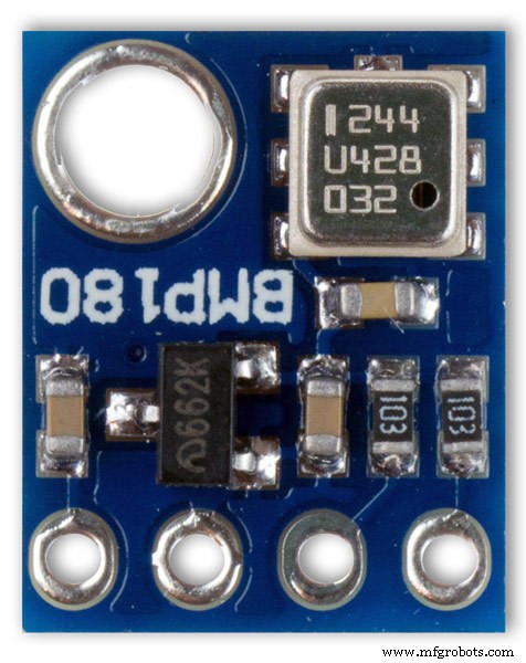
BMP180 압력 센서 모듈 2 끄기 그림 5 BMP180 브레이크아웃은 I2C("와이어") 인터페이스가 있는 기압 센서입니다. 기압 센서는 주변 공기의 절대 압력을 측정합니다. 이 압력은 날씨와 고도에 따라 다릅니다. 데이터를 해석하는 방법에 따라 날씨의 변화를 모니터링하고 고도를 측정하거나 정확한 기압 판독이 필요한 기타 작업을 수행할 수 있습니다.
+, -, CL 및 DA 핀을 Arduino에 연결합니다.
CL은 SCL로, DA는 SDA로 이동합니다.
중요:전원 핀(+ 및 -)을 3.3V 전원에만 연결하십시오. 더 큰 전압은 부품을 영구적으로 손상시킵니다. I2C는 오픈 드레인 드라이버를 사용하기 때문에 I2C 핀(DA 및 CL)을 5V 마이크로프로세서의 I2C 포트에 연결하는 것이 안전합니다.
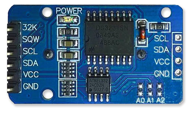
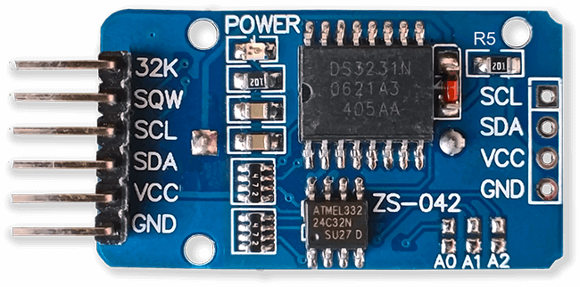
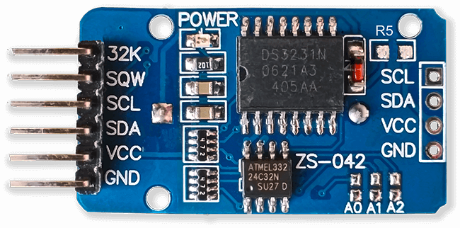
RTC 실시간 시계 그림 6
이 브로미터는 DS3231 AT24C32 I2C 정밀 실시간 클록 모듈을 사용합니다.
이 모듈은 주로 타이밍에 사용되지만 LCD 디스플레이에 타임스탬프도 제공합니다. 시간은 UTC로 설정되며 여름철에는 변경되지 않습니다. 모듈은 리튬 이온 충전식 배터리와 함께 제공됩니다(위의 다이어그램 참조). 저는 비충전식 배터리를 사용하므로 모듈에서 저항 R5를 제거했습니다. 자세한 내용은 RTC 수정 섹션을 참조하세요.
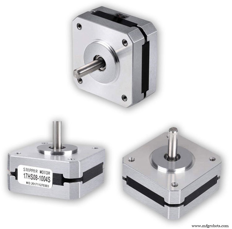
스테퍼 모터 3 꺼짐 기압계는 3개의 Nema 17 스테퍼 모터 1A, 13N.cm 홀딩 토크, 4-리드, 1.8°를 사용합니다. 계단이 360°에 200번 정확하게 맞기 때문에 1.8° 모터를 사용했습니다. 원하는 경우 Nema 8 모터를 사용할 수 있지만 28BYJ-48-5V 모터에는 필요한 1.8° 스텝 각도가 없으므로 사용하지 마십시오.
내 기압계 다이얼의 경우 360°로 정확하게 분할되므로 1.8° 단계 각도가 필요합니다.
LCD 디스플레이 2 꺼짐
저는 2개의 20x4 LCD 디스플레이를 사용했는데 하나는 기압계, 시계 및 6시간 디스플레이용이고 다른 하나는 3시간 디스플레이 및 예보용입니다.
12단계:모듈/구성 요소 A4988 스테퍼 모터 드라이버
A4988 마이크로스테핑 바이폴라 스테퍼 모터 드라이버 3 끄기
중요 이 섹션을 주의 깊게 읽으십시오
내 기압계는 1/16 단계 회전으로 설정되고 그에 따라 코드가 조정됩니다.
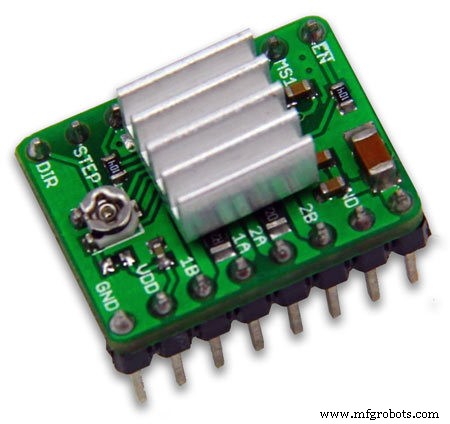
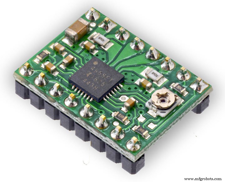
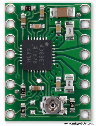
A4988 마이크로스테핑 바이폴라 스테퍼 모터 드라이버 pic.1 및 방열판 없음 pic.2
Allegro의 A4988 마이크로스테핑 바이폴라 스테퍼 모터 드라이버용 이 브레이크아웃 보드는 전류 제한 조정, 과전류 및 과열 보호, 5가지 마이크로스텝 분해능(최대 1/16단계)이 특징입니다.
8V ~ 35V에서 작동하며 방열판이나 강제 공기 흐름 없이 위상당 최대 약 1A를 전달할 수 있습니다(충분한 추가 냉각으로 코일당 2A 정격).
다음은 드라이버의 주요 기능 중 일부입니다. 간단한 단계 및 방향 제어 인터페이스 더 높은 단계 속도를 달성하기 위해 스테퍼 모터의 정격 전압보다 높은 전압을 사용할 수 있는 전위차계 포함 올바른 전류 감쇠 모드(빠른 감쇠 또는 느린 감쇠)를 자동으로 선택하는 지능형 초핑 제어 과열 열 차단, 저전압 잠금 및 교차 전류 보호 접지 단락 및 단락 부하 보호
전원 연결 드라이버는 VDD 및 GND 핀에 연결하려면 논리 공급 전압(3 – 5.5V)이 필요하고 VMOT 및 GND에 연결하려면 모터 공급 전압(8 – 35V)이 필요합니다. 이러한 공급 장치에는 보드에 가까운 적절한 디커플링 커패시터가 있어야 하며 예상 전류를 전달할 수 있어야 합니다(모터 공급 장치의 경우 최대 4A).
경고:이 캐리어 보드는 낮은 ESR 세라믹 커패시터를 사용하므로 특히 몇 인치보다 긴 전원 리드를 사용할 때 파괴적인 LC 전압 스파이크에 취약합니다. 올바른 조건에서 이러한 스파이크는 A4988의 최대 정격 전압 35V를 초과할 수 있으며 모터 공급 전압이 12V만큼 낮더라도 보드를 영구적으로 손상시킬 수 있습니다. 드라이버를 보호하는 한 가지 방법은 다음과 같습니다. 이러한 스파이크는 모터 전원(VMOT)에 걸쳐 큰(최소 47μF) 전해 커패시터를 배치하고 보드에 가까운 어딘가에 접지하는 것입니다.
모터 연결
4선, 6선 및 8선 스테퍼 모터는 제대로 연결된 경우 A4988로 구동할 수 있습니다. Warning:Connecting or disconnecting a stepper motor while the driver is powered can destroy the driver. (More generally, rewiring anything while it is powered is asking for trouble.)
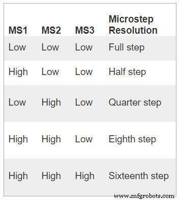
Step (and microstep) size
see table pic. 3Stepper motors typically have a step size specification (e.g. 1.8° or 200 steps per revolution), which applies to full steps. A microstepping driver such as the A4988 allows higher resolutions by allowing intermediate step locations, which are achieved by energizing the coils with intermediate current levels. For instance, driving a motor in quarter-step mode will give the 200-step-per-revolution motor 800 microsteps per revolution by using four different current levels.
The resolution (step size) selector inputs (MS1, MS2, and MS3) enable selection from the five step resolutions according to the table below. MS1 and MS3 have internal 100kΩ pull-down resistors and MS2 has an internal 50kΩ pull-down resistor, so leaving these three microstep selection pins disconnected results in full-step mode. For the microstep modes to function correctly, the current limit must be set low enough (see below) so that current limiting gets engaged. Otherwise, the intermediate current levels will not be correctly maintained, and the motor will skip microsteps.
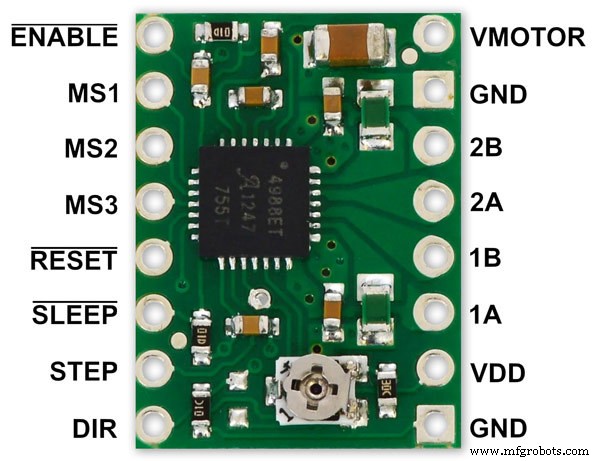
Control inputs
pics 4 &5Each pulse to the STEP input corresponds to one microstep of the stepper motor in the direction selected by the DIR pin. Note that the STEP and DIR pins are not pulled to any particular voltage internally, so you should not leave either of these pins floating in your application.
If you just want rotation in a single direction, you can tie DIR directly to VCC or GND. The chip has three different inputs for controlling its many power states:RST, SLP, and EN. For details about these power states, see the datasheet.
Please note that the RST pin is floating; if you are not using the pin, you can connect it to the adjacent SLP pin on the PCB to bring it high and enable the board.
Current LImiting Before connecting the motor we should adjust the current limiting of the driver so that we are sure that the current is within the current limits of the motor. We can do that by adjusting the reference voltage using the potentiometer on the module to set the VRef.
See details on the video link pic. 6
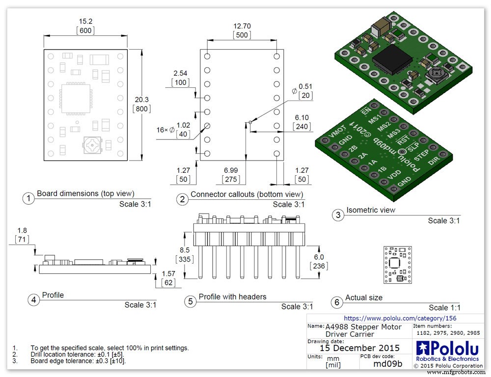
Manufacturers Drawing sheet pic.7
Step 13:Construction Prototyping
The circuit was prototyped using a hardboard dial with holes drilled for the motor spindles and LEDs.
Various dial designs were then printed on normal paper and Sellotaped over the top. The LED wiring loom was made with the LEDs in position on the temporary dial.
If you are using the round dial design this will allow you to check if the board etc will be mounted on the dial or in the back box.
Step 14:Construction RTC Modification
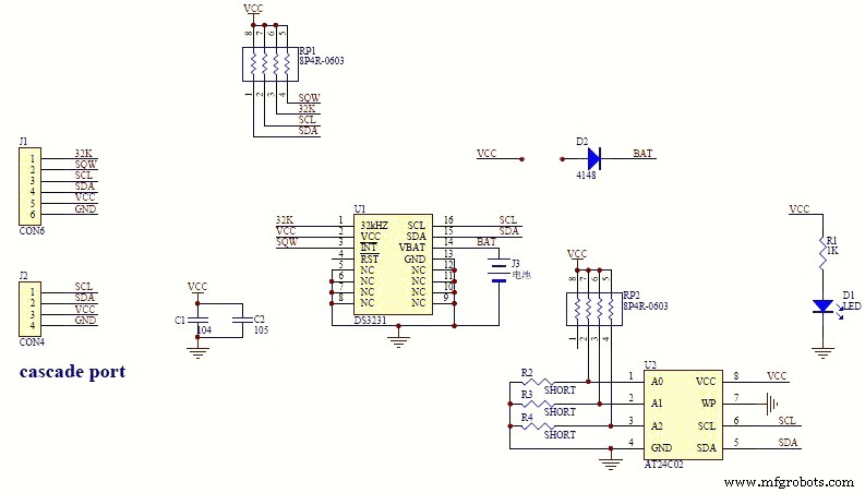
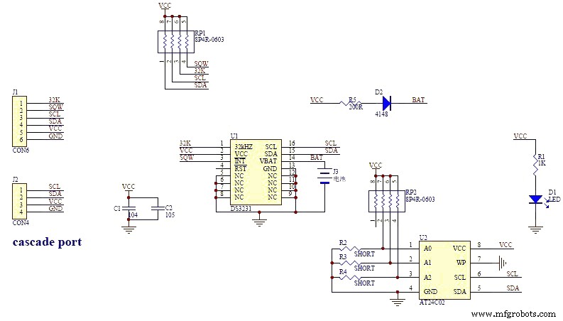
The module comes supplied with a Lithium-Ion rechargeable battery see diagram pic. 2.
I use a non rechargeable battery (I am not happy with the circuit design with a lithium-iron battery and associated fire risk) of the so have removed resistor R5 from the module as below. This stops any charge current to the battery.
Pic.3 shows the module without the resistor (just break it off) and pic.4 the modified circuit.
Step 15:Construction Mounting Modules &Boards
On the modern square dial design all the modules and boards are mounted on the dial. The classic round dial desgn will need some parts mounted in the back box as there is less space on the dial.
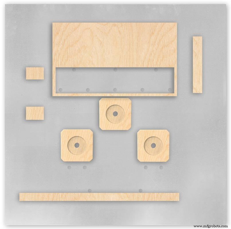
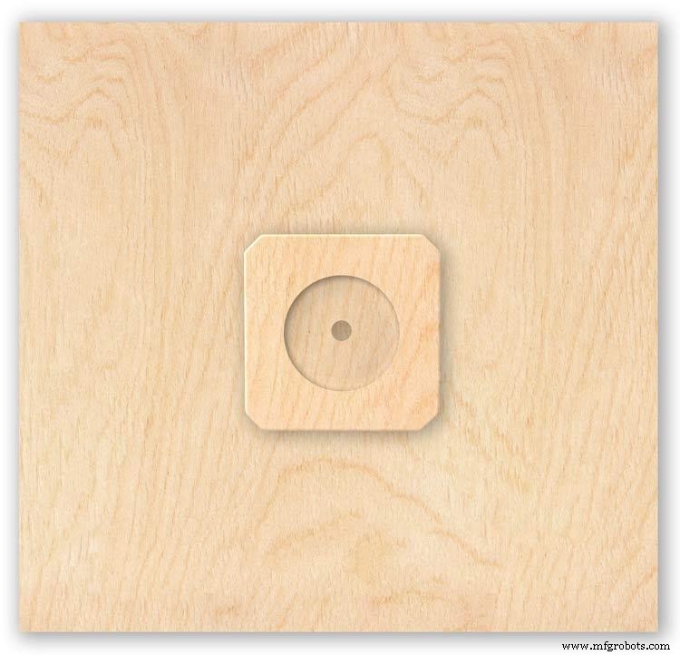
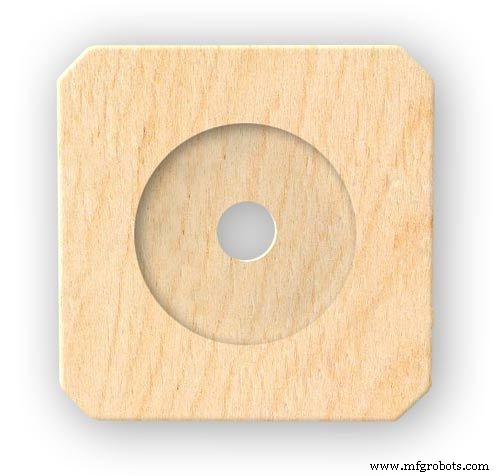
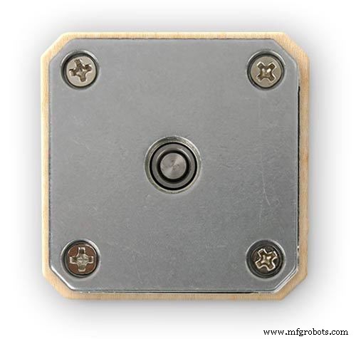
Motors are hot melt glued to wooden mounting blocks pic.1&2. The wooded blocks are cut fron a sheet of plywood pic.3. The mounting blocks depths are set to allow the correct protrusion of the spindles through the dial. I have hot melt glued the blocls to the dial.
The Vero Boards and LCD displays are also screwed to wooden blocks which have been glued to the dial using impact adhesive.
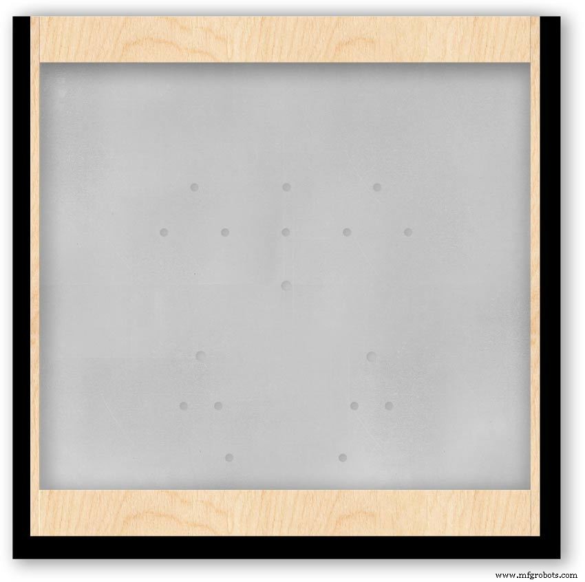
Pic.4 shows the front view with a transparent dial showing mounting locations.
Pic. 5 shows the same but the rear view.
Pic.6 shows the wooden mounting blocks locations and layout.
Pic.7 shows the modules and motors mounted on the blocks.
Step 16:Construction LED Fixing

The 3mm LEDs are mounted so they just show above the surface of the dial pic.1.
3mm holes are drilled and hot melt glue holds them in place.
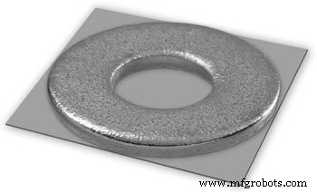
To get a uniform depth I made a jig using a washer and piece of card glued to it pic.2.When fixing the LEDs the jig is pressed against the dial with the depth of the washer setting the protrusion of the LED through the dial.
Step 17:Construction Classic Style English Dial Clock Case
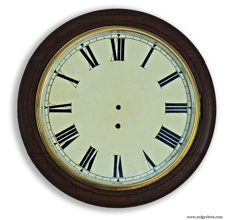

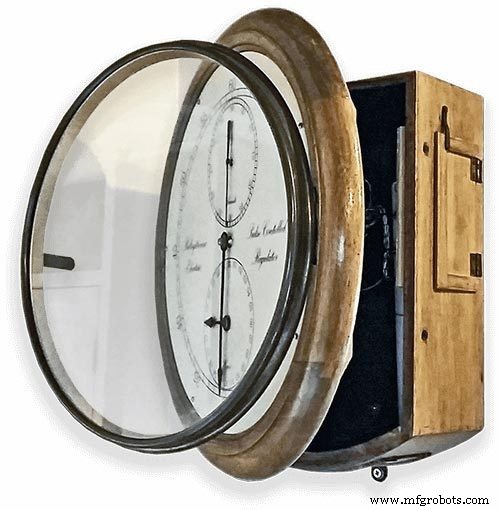
The classic 12" Dial Clock case can be purchased from Ebay as "case only" pic.1.
Various styles are available this one is oak and has a dial surround that hinges away from the back box pic.2.
This makes for a very easy build as all the hard work has been done. The dial is mounted by 3 small wood screws hidden behind the brass dial bezel.
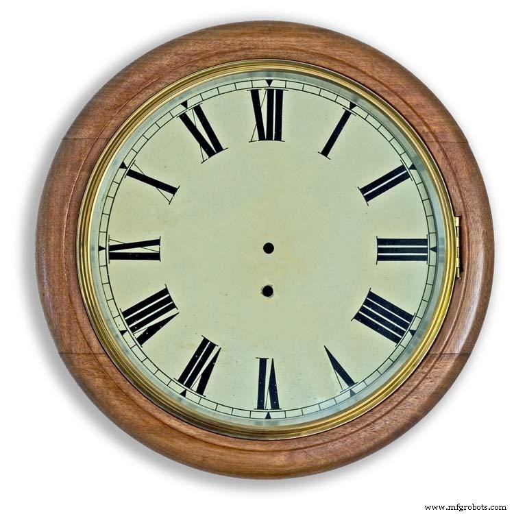
This dial surround has been stripped and bleached to bring out the original light colour of the wood pic.3.The dial was removed as it had a winding hole off center.
A new dial was cut from a sheet of alluminium pic.4.
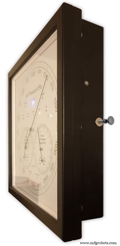
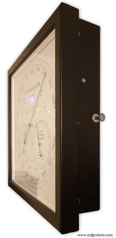
Pic.5 side view of the Barometer showing the back box.
Pic.6 shows my regulator clock case with original curved back box, hinged dial bezel and pegged dial surround.
Many of these clock cases were held in place by four wooden pegs. If your case is constructed like this add a pair of hinges to one side and use the remaining two pegs to lock the dial surround in place.
Step 18:Construction Modern Case


Picture Frame Version
I have used two identical picture frames mounted back to back. These frames are 30cm x 30cm approx. 12"x12" pic.1.
pic.2 Frames are joined back to back.
pic.3 This gives a double depth frame.
pic.4 Rear side view showing wired boards and modules.
pic.5 The dial viewed through the rear frame.
pic.6 Rear half of the frame with all wiring in place.
pic.7 The front of the dial now shows through the front half of the frame. Wooden bevels hide the space behind the front half of the frame.
Step 19:Construction Modern Case Backbox
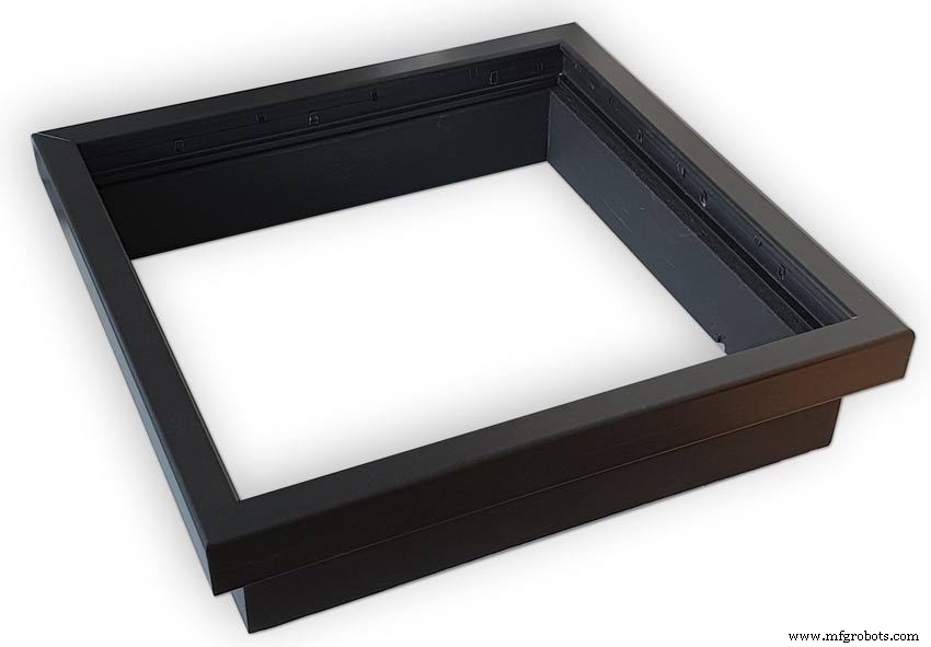
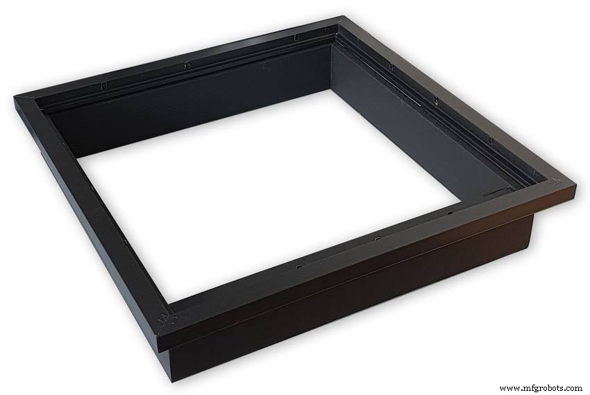


Back Box
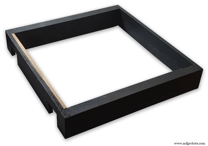
Pic.1 The barometer is housed in a back box that is smaller than the dial frame on all side apart from the top. The fram overlap helps hide the back box and adds a shadow effect to the case on the wall.
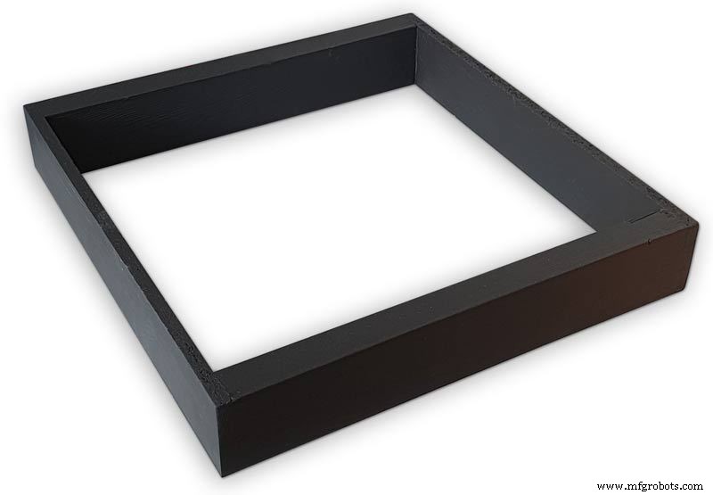
Pic.2 The back box is 50mm deep and is simply constructed of glued and screwed wood.
Pic.3 Rear view of back box in position behind rear dial frame showing the frame overlap.
Pic.4 The screw holes are filled then a coat of matt black is applied to the back box.
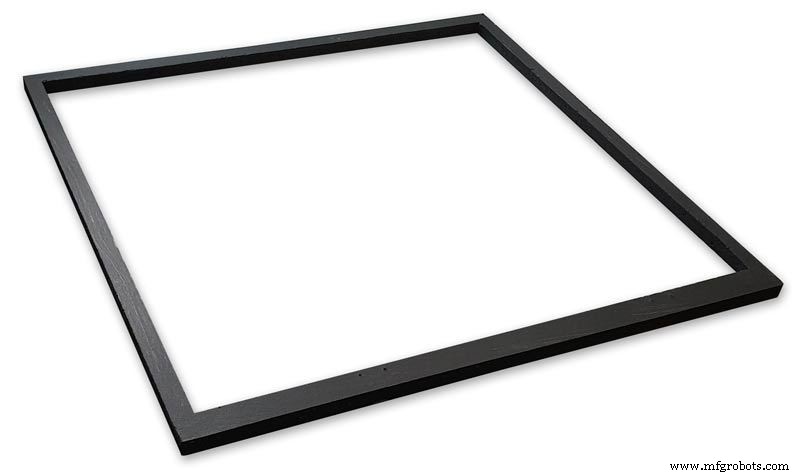
Pic.5 Back box with rear picture frame in place this holds the dial.Note the rear frame is placed upside down.
Pic.6 A spacer is cut the same size and depth as the recess of the picture frame.
Pic.7 The spacer is set under the dial.
Pic.8 This will raise the dial level with the top edge of the rear frame.
Pic.9 Back box with front picture frame in place on top of the rear frame.This frame holds the glass.
Step 20:Construction Modern Case Wall Mounting
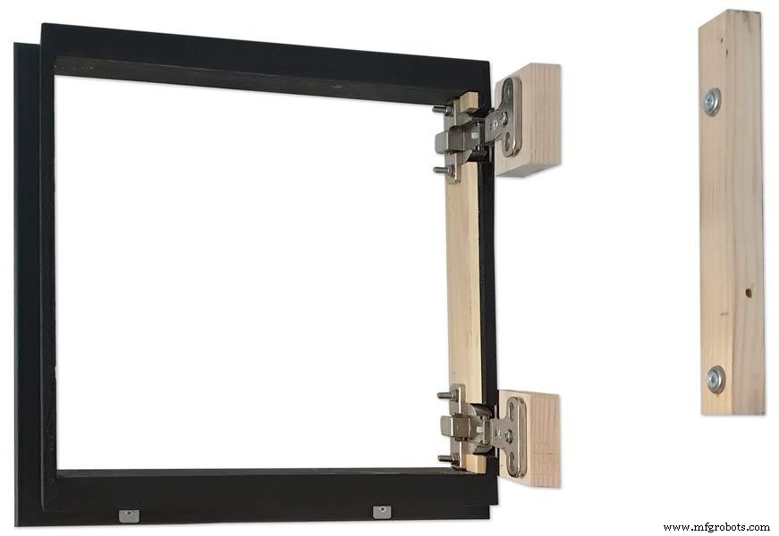


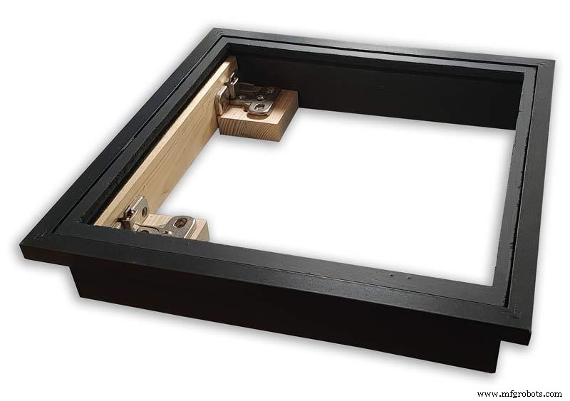
Mounting the Barometer
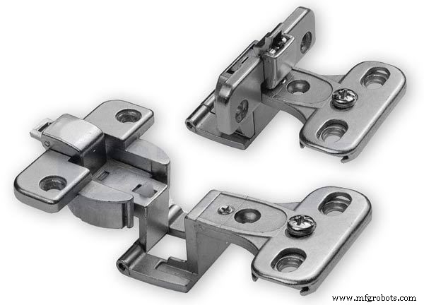
Pic.1 To allow access to the rear of the Barometer I have mounted it on a pair of GTV 270° inset hinges. The hinges are mounted on a block of wood fixed to the wall and allow the barometer to be swung out for access. The hinges also have a quick release function if the Barometer needs to be taken down for maintenance at any time. The hinge pivot is set back which also allows the top of the case to clear the wall when hinged out.
Pic.2 The hinges are mounted on wooden blocks screwed to the wall.
Pic.3 I have screwed and glued an extra piece of timber to the left hand side where the hinges will mount.This will add strength as all the weight of the clock will be on this side when the clock case is open. Two aluminium plates will cover the hinge holes.
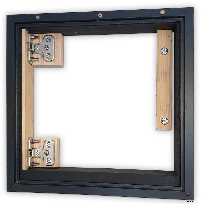
Pic.4 Hinge blocks in place. Note these are bolted through the case rather than screwed.
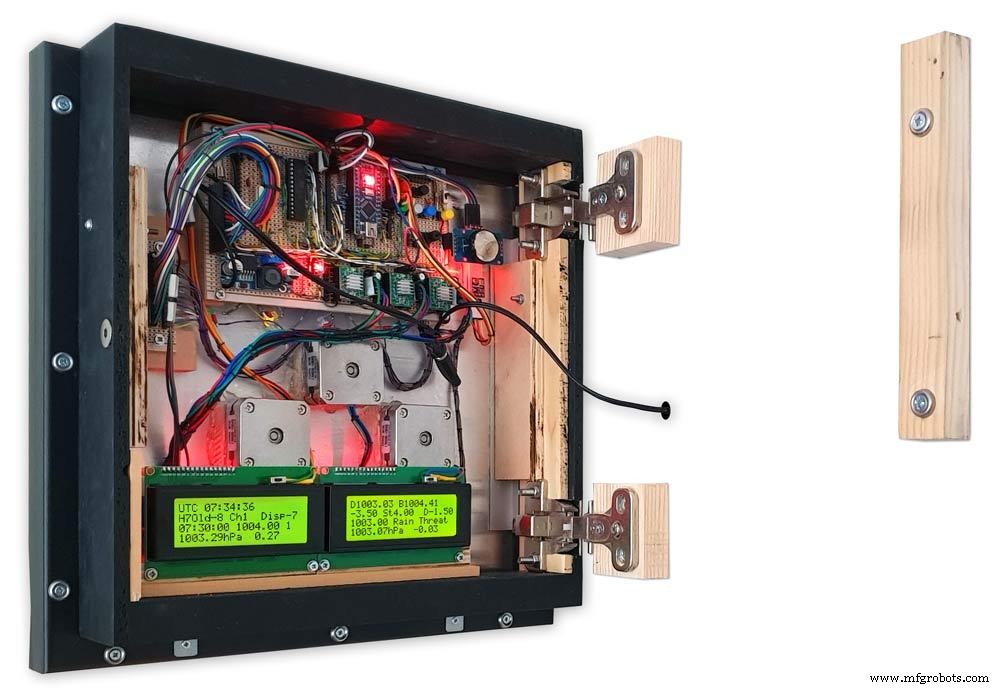
Pic.5 Back Box mounted on the wall. The fixing screws also hold the hinge to the wooden mounting blocks The wooden baton on the right is also fixed to the wall and supports the top right hand corner of the back box. It also serves as a fixing point for the wall mount locking pins that holds the back box shut against the wall.
Pic.6 The back box is shown open with the wooden mounting blocks and batons fixed to the wall. The hole in the front edge of the baton aligns with a hole in the side of the back box. A steel pin is inserted here to lock the barometer shut against the wall.
Pic.7 Back box open allowing access to the LCD displays and setting switches.
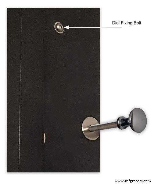
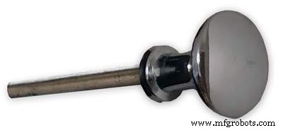
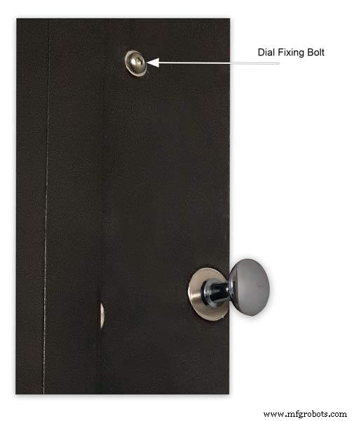
Pic.8 Steel Locking Pin This is a small cabinet knob with a length of treaded bar screwed into the thread.
Pic.9 &10 The locking pin when pushed fully in lock the barometer against the wall. When pulled out the barometer is able to swing out to allow access to the control switched and LCD displays.
Pic.11 Detail of Locking Pin and location of right side dial fixing bolt. I have glued a washer in place over the hole as an escutcheon plate.
Step 21:Construction Modern Case Dial Mounting


The dial and all the boards etc are removable for maintenance and is held to the backbox by 2 bolts.
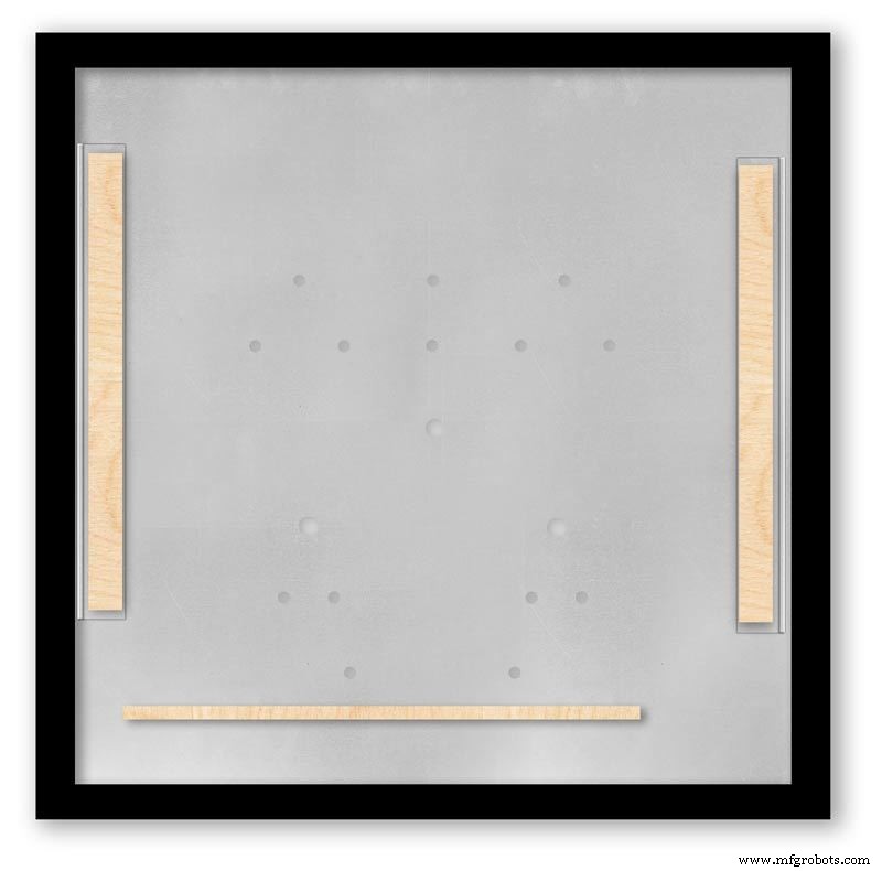
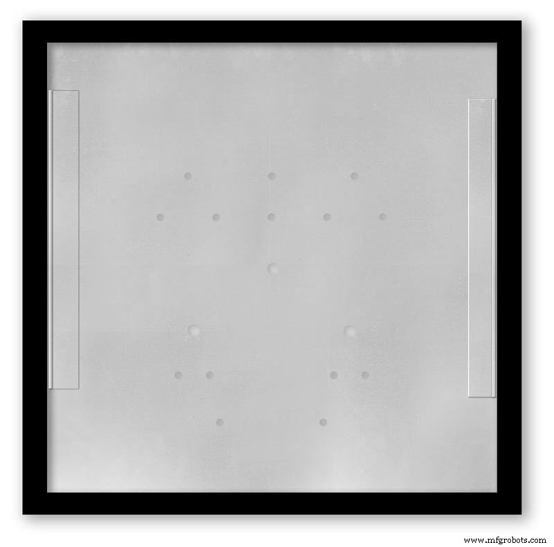
Mounting the Dial in the Back Box
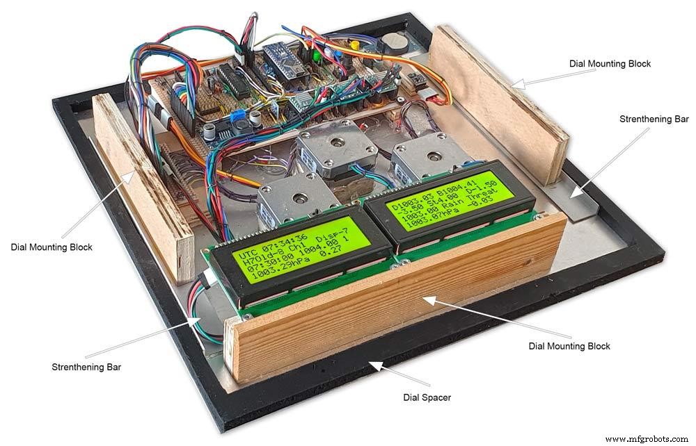
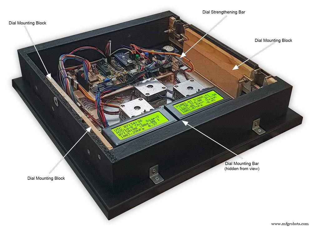
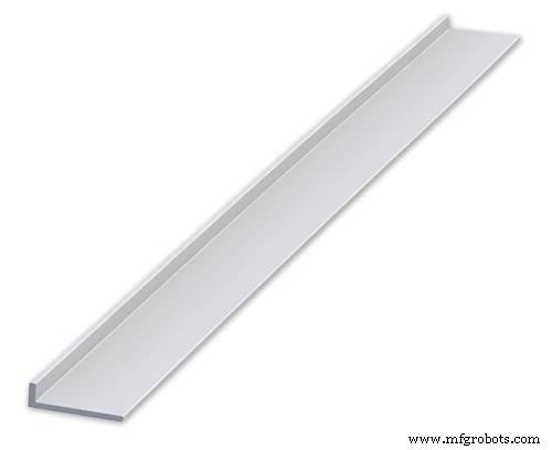
The dial holds the combined weight of all the stepper motors, boards and modules and is stiffened by impact gluing two strips of unequal aluminium angle to it's rear surface.Two blocks of wood are then glued to these bars and small screws then hold these wooden blocks through the side of the back box. A further thin strip of wood is glued to the dial below the LCD mounting block. This is not screwed to the case but sits on the back box to support the dial.
Pic.1 Strengthening bar of alluminium unequal angle.
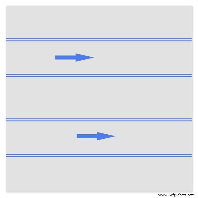
Pic.2 Strengthening bar locations.
Pic.3 Glued wooden fixing/support blocks for dial fixing bolts left and right and glued dial support lower.
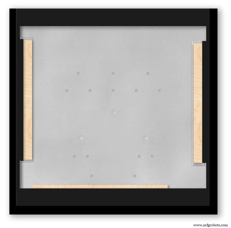
Pic.4 Shows contact/fixing points between the back box and dial. Back box in black with dial fixings/support in wood.
Pic.5 Rear view showing mounting block and bar locations.
Pic.6 Dial with Back Box Removed showing mounting blocks and strengthening bars glued to the rear of the dial.
The dial spacer allows the dial to sit flush with the top of the rear picture frame.
Pic.7 Right side of clock showing dial fixing bolt location.
Pic.8 A mount is constructed from 4 thin strips of wood and is placed in the recess of the front picture frame. This fills the gap between the picture frame and dial, holds the Perspex sheet in place and also adds a photo mount effect to the dial.
Pic.9 Mount in place behind the front picture frame.
Step 22:Contruction Dial
Pic.1 The dial is made from 1.5mm thick alluminium sheet and comes covered with a protective plastic film.
Pic.2 From your cad program print out the dial on A3 paper and include center marks for all the LED and stepper motor shaft holes.This will be your drill template.Lay the paper of the alluminium dial blank and tape the edges to stop it moving.Center punch all the holes through the paper.
Pic.3 Remove the paper template and drill out the holes 3mm for the LEDs and 3 larger holes for your stepper motor spindle.
Start with a small pilot hole and increase the drill size in 3 stages. If you are using a round dial mark it out on the projective film with a market pen and cut it out at this stage.
Pic.4 The protective plastic film can now be removed. Rub down the dial back and front to remove any burrs and to provide a key for the paint.
Pic.5 Spray a coat of acrylic primer and then your choice of top coat - I have used antique white.
I then give a final coat of matt clear acrylic. Leave to dry over night.
I have included a high res pic of the dial pic.6. Contact me if you need it in another format. My CAD format is TurboCad.
Step 23:Construction Dial Decal
Apply the water slide decal transfer.
I use Water Slide Decal paper from BIGBITE Studio They have some good tutorials on their site. https://www.bigbitestudio.co.uk/tutorials/water-decal-tutorials/
Pic.1 Water slide decals are printed out on an inkjet printer soaked in water then slid into place. They give a very detailed print and once given a coat of varnish are tough.
Don't forget to order transparent transfers so the dial colour can be seen through the transfer.Follow the instructions with the pack as they do vary.
Pic.2 On my transfers I print out the dial on transfer paper let it dry and then cut it out to just under the size of the dial. I then give it a coat of acrylic varnish.
I set my printer as follows:Plain Paper, Photo &High Speed Off This stops my printer from over inking the paper When the varnish is dry the transfer is soaked in water until the transparent transfer comes away from the white backing sheet.
Pic.3 Move the soaked transfer over the dial.
Pic.4 Slide the transfer into position.
Pic.5 Gently pull the white backing paper backward while holding the transfer down.
Make sure the crosses line up with the center of all the holes.
Pic.6 Get rid of any air bubbles.
Pic.7 Then leave it to dry before adding a coat of matt varnish.
After the coat of varnish break through the layer of transfer over the holes using the back of a drill bit jus smaller than the holes. Then give a final coat of varnish to seal the edges around the holes.
Step 24:Construction Hands

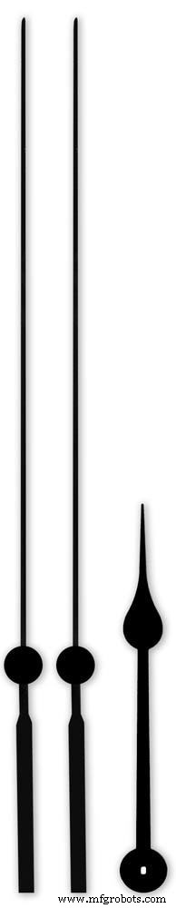


Hands are a very personnal choice and there are many diffent styles to choose from. The hardest part is finding hands that match each other. I found a perfect set of small hands but was unable to find a matching longhand for the main barometer. In the end I made my own from 3 donor hands.
All my hands were quartz second hands so I hand to file the mounting spindle off the back for mounting on the stepper motor spindle.
On some stepper motors the spindle can be drilled out to take the hand spindle but my spindles were too hard to drill.
Pic.1 my completed hands.
Pic.2 The long barometer hand was constructed from 3 different hands
Pic.3 To get the lower spade balance part of the hand I used a spade hand.
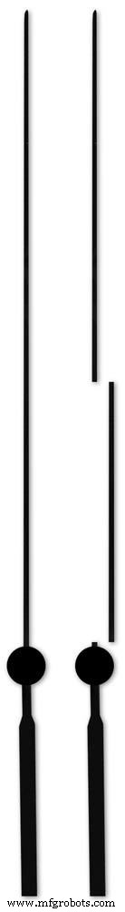
Pic.4 First I cut off the top using sharp scissors.
Pic.5 The top was then trimmed by cutting the point off.
Pic.6 The remaining part was then filed away to match the shape of the 2 smaller hands.
Pic.7 The completed balance for the hand.
Pic.8 To make the front pointer and center I cut the end off one off my donor hands.
Pic.9 To make the rear balance shaft I cut a section out of the 3rd donor hand.
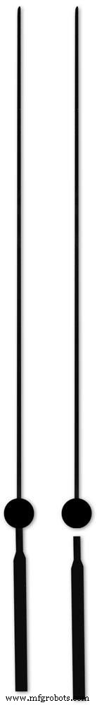
Pic.10 Left the 3 parts of the new hand. Middle shows the overlap of the balance shaft to allow for bonding. Right pic shows the balance shaft bonded with impact adhesive to the underside of the balance and center shaft.
To fix the hands to the stepper motor spindle I did not want to use impact adhesive as the hands are fragile and would be damaged if I hand to remove them. In the end I went for a tiny bit of Blu Tack on each hand. Blu Tack is putty like and is non setting but seems to hold very well!
Step 25:Construction Schematic
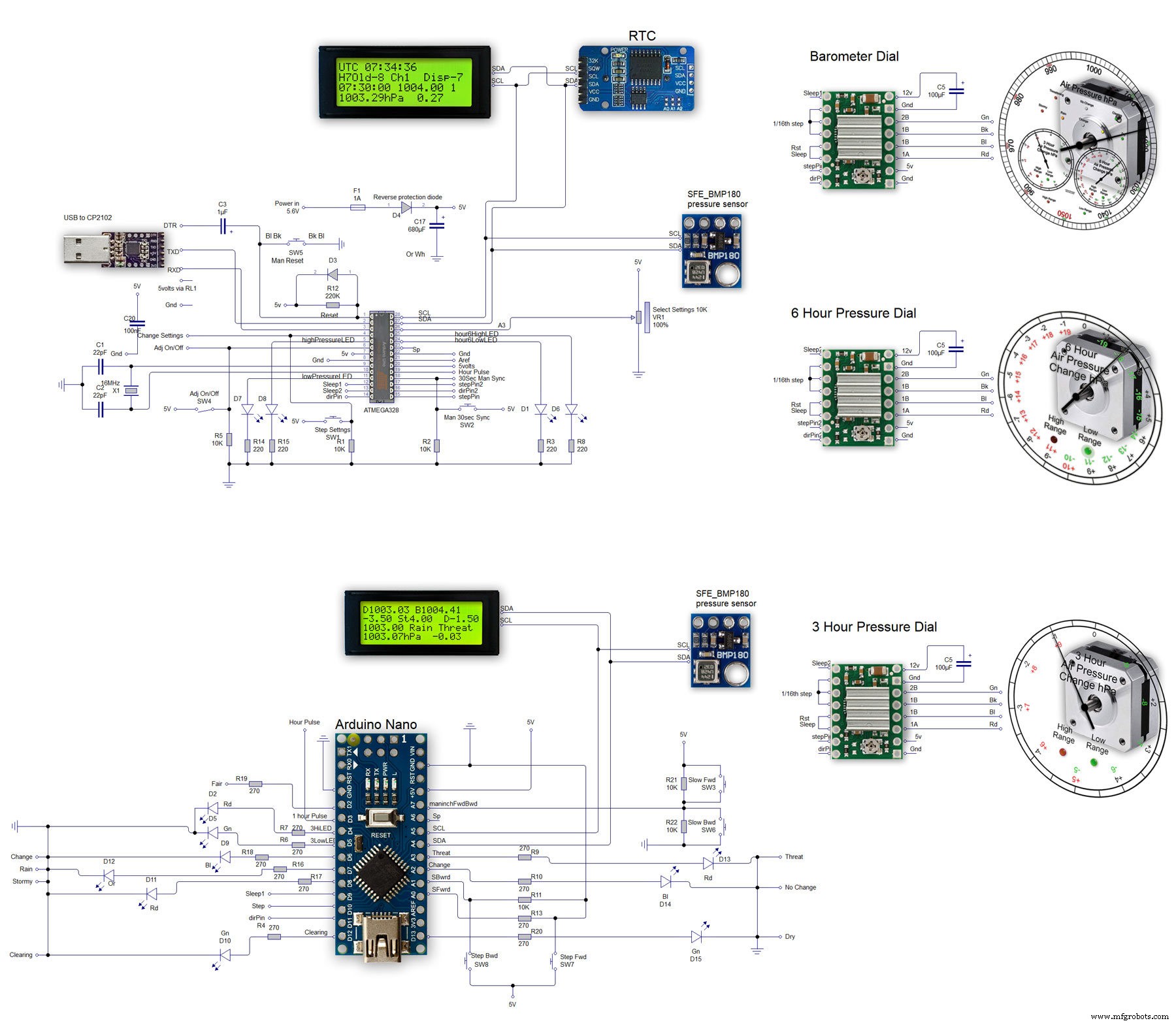
The main shematic is shown in Pic. 1 with the power supply in Pic.2.
You will also need a regulated plug in 12v supply adaptor of around 1amp.
Note I have fitted switches on the LCD displays to turn the backlight LEDs On and Off. This is optional but as the displays are not visible for 99.99% of the time it will save power.
Note larger schematics can be found on my web site here
Step 26:Construction Vero Board
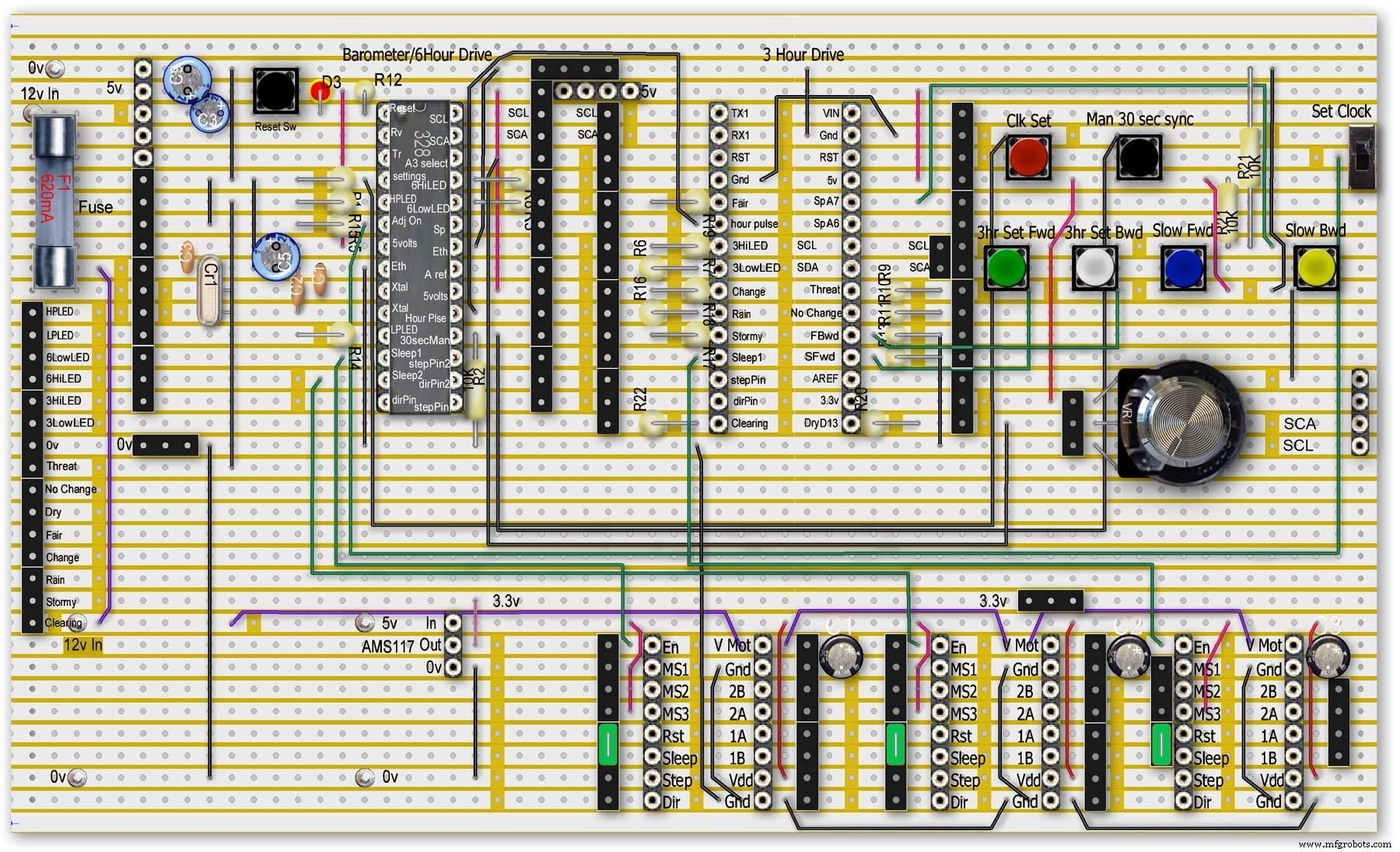
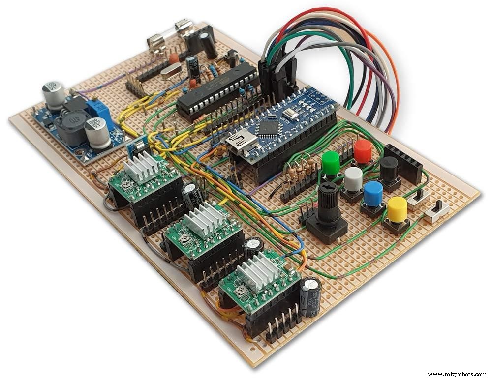
Vero Board Layouts
Pic.1 Vero Board with all modules removed.
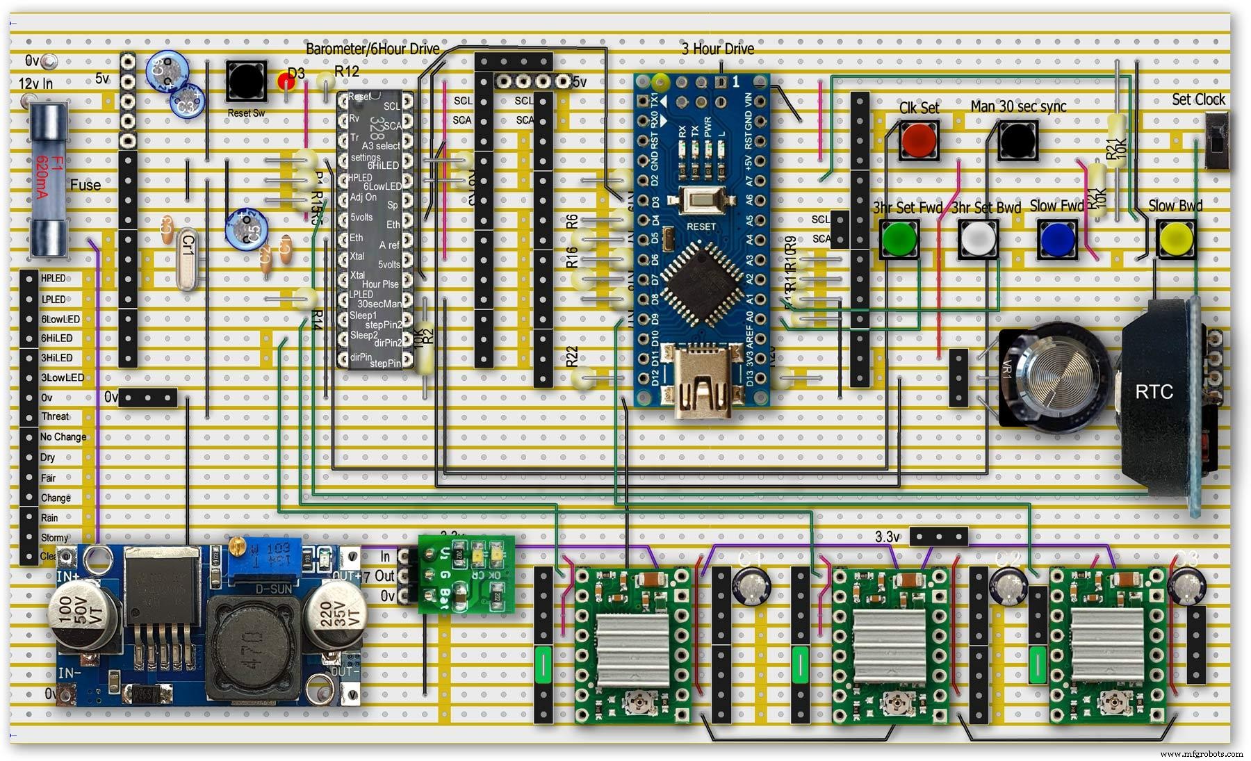
Pic.2 Vero Board with modules in place.
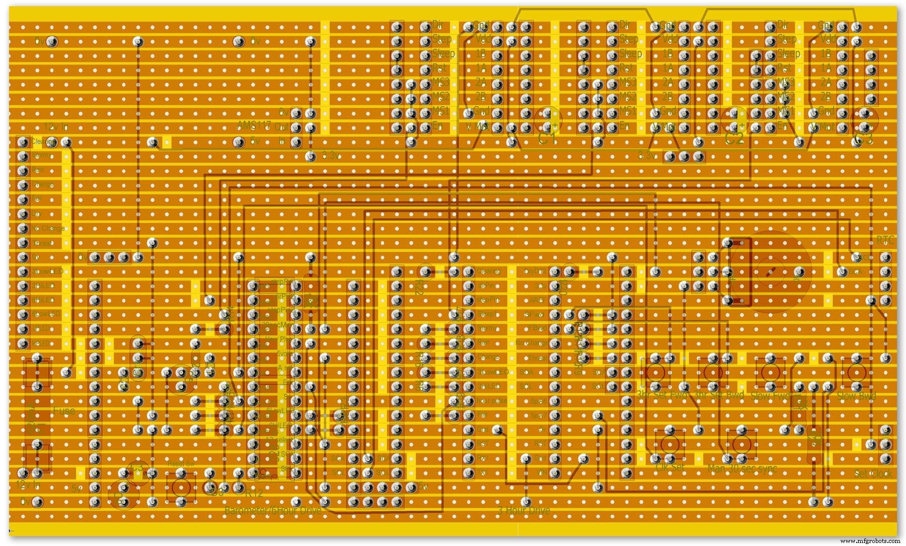
Pic.3 Vero Board rear view (flipped down from top).
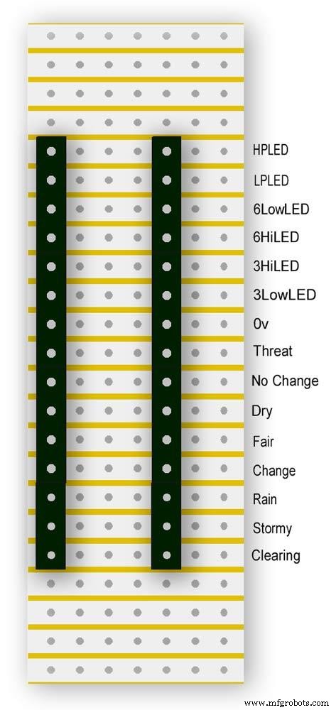
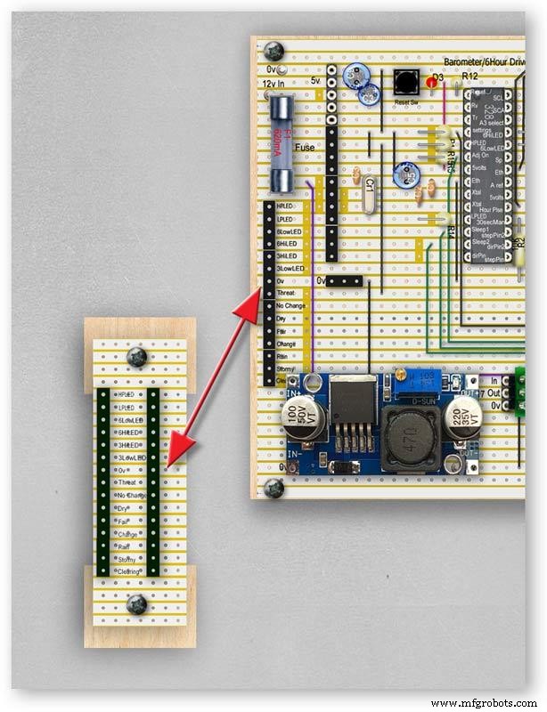
Pic.4 LED Vero Board
This board is used as a connection point for the dial LEDs. This allows the dial to be disconnected from the main board if required for maintenance.
Pic.5 The LED Vero Board connects to the main board with Dupont sockets and male Dupont cable
Pic.6 Vero Board wiring in progress.
Pic.7 Vero Boards and module location on the rear of the dial.
Step 27:Code
Code
There are 2 parts to the code 1 for the Main Barometer Code and 6 hour display and 1 for the 3 hour display and weather forecast.
Step 28:Time-Lapse Video
Time-Lapse Video showing rain radar and the Barometer predicting rain and a storm.
This is a 4K video so you should be able to see full details of the dial and forecast LEDs.
<섹션 클래스="섹션 컨테이너 섹션 축소 가능" id="코드">/* Example sketch to control a 28BYJ-48 stepper motor with ULN2003 driver board, AccelStepper and Arduino UNO:number of steps/revolutions. More info:https://www.makerguides.com v4 moved step 6 hour pressure step from void getpressure 1523 to main loop check every hour 365v5 remove unwamted step elementsv6 convert to diff display on 6 hr motorv8 modified hour change formula 1486v9 sleepv10 chnged high/low for EN control v11 chenge calc for hour change 1380v12 added calcCurrentDisp (); to calc current time from line 1384v13 removed 30 sec syncv14 air pressure extremes LEDsv15 add hour diff hour calc etc to row 1 when not on settingsv16 adding 16th stepsv17 errorv18 change min pulse to hour pulse on the hour + 1minv19 check enable and sleepsv20 added DAC to NANO so pins changed on 328 to match (analogue and digital swapped A6 D3 - deleted v20 also changed Low range hi range to both light above 19 or -19v21 same as 20 with serial print removedv23 notes added LCD display info added to startup */#include//SFE_BMP180 pressure sensor#include #include #include // ######## You will need to create an SFE_BMP180 object, here called "pressure":SFE_BMP180 pressure;#define ALTITUDE 118.0 // Altitude of Kenley Surrey in meters// also used to adjust/sync/calibrate to nearby weather station/3 hour display//#########//**********************// set the LCD address to 0x27 for a 20 chars 4 line display// Set the pins on the I2C chip us ed for LCD connections:// addr, en,rw,rs,d4,d5,d6,d7,bl,blpolLiquidCrystal_I2C lcd(0x27, 2, 1, 0, 4, 5, 6, 7, 3, POSITIVE); // Set the LCD I2C address#define DS3231_I2C_ADDRESS 0x68// Convert normal decimal numbers to binary coded decimalbyte decToBcd(byte val){ return( (val/10*16) + (val%10) );}// Convert binary coded decimal to normal decimal numbersbyte bcdToDec(byte val){ return( (val/16*10) + (val%16) );}// Include the AccelStepper library:#include // Define stepper motor connections and motor interface type. Motor interface type must be set to 1 when using a driver:#define dirPin 8#define stepPin 9#define dirPin2 10#define stepPin2 11#define motorInterfaceType 1// Create a new instance of the AccelStepper class:AccelStepper stepper =AccelStepper(motorInterfaceType, stepPin, dirPin);//barometer motorAccelStepper stepper2 =AccelStepper(motorInterfaceType, stepPin2, dirPin2);// 6 hour motorfloat seaPressure =0;float pressureNow =0;float pressurePrevious =0;float pressureDiff =0;int checkStop =0;int pressureRndDiff =0;int pressureRndNow =0;int pressureRndPrevious =0;int adjustOn =4; // allows adjustment of barometer// int test =0; // test mode 0 off 1 is onchar status; double T,P,a;//int h =0;//int m =0;//int j =0;int stepcount =0;int time =0;int resetmins =1;int secondNow =0;int secondPrevious=0;int minuteNow =0;int minutePrevious=0;int hourNow =0;int hourPrevious=0;int hourNow1=0;int hourPrevious1=0;int initial =0;int initial1 =0;int initial3 =0;int highPressureLED =3;int lowPressureLED =5;int hour6LowLED =15;int hour6HighLED =16;int manSync =12; // resets seconds to 30 secondsint changeSetting =2;int syncStop =0;int sync30Stop =0;int stepoffHour =0;int stepoffHourbkw =0;int stepoffMin =0;int stepoffMinbwd =0;int stepoffRTCminfwd =0;int stepoffRTCminbwd =0;int stepoffRTChourfwd =0;int stepoffRTChourbwd =0;int settingreadPin =A3; //Pin for sensing analogue value from potint settingVal =0; // Analogue value 0-1023int LCDstop =0; // stops settings on LCD display refreshing until they changeint hourPulse =13; //min pulse for seconds display was 14int adjustLock =0; // turns off adjust lockint hourcalc =0; // number from 0 to 7 representing the 8 hours of stored pressure readings int hourDiff =0; // used to check if 6hour previous motor should be stepped.int hourChange =0; // the amount of 6 hour to stepint currentDisplay =0; //current 6hour change readingint hour0 =1013; // you can set last 8 hours pressure here or leave at 0 and theint hour1 =1014; // readings will catch up over the next 8 hoursint hour2 =1015;int hour3 =1016;int hour4 =1016;int hour5 =1016;int hour6 =1012;int hour7 =1013;int sleep1 =6;int sleep2 =7;// check air pressure here https://www.meteoplug.com/cgi-bin/meteochart.cgi?draw=a3aeaaa1acbdf9f1fcfed4fedbc2c094c0d6d6d1d2c5edcebbfee9ffeff1fbf9//int Disp3hrIn =A3;//int Disp3hrVal =0;void setup() { pinMode(adjustOn, INPUT); pinMode(hourPulse, OUTPUT); pinMode(highPressureLED, OUTPUT); pinMode(lowPressureLED, OUTPUT); pinMode(hour6LowLED, OUTPUT); pinMode(hour6HighLED, OUTPUT); pinMode(manSync, INPUT); pinMode(sleep1, OUTPUT); pinMode(sleep2, OUTPUT); pinMode(settingreadPin, INPUT); // Set the maximum steps per second:stepper.setMaxSpeed(1000); stepper2.setMaxSpeed(1000); lcd.begin(20,4); // initialize the lcd for 20 chars 4 lines, turn on backlight lcd.backlight(); // backlight on not needed as man controlled lcd.setCursor(0,0); //Start at character 0 on line 0 lcd.print("Barometer A988"); //@@@@@@@@@@@@@@@@@@@@@@@@@@@@@@@@@@@@@@@@@@@@@@@@@@@@@@@@@@@@@@@@@@@@@@@@@@@@@@@@@@@@@@@@@@@@@@@@@@@@@@@@@@@@@@@@@@@@@@@@@@@@@@@@ lcd.setCursor(0,1); //Start at character 0 on line 1 lcd.print(" Version 23"); //@@@@@@@@@@@@@@@@@@@@@@@@@@@@@@@@@@@@@@@@@@@@@@@@@@@@@@@@@@@@@@@@@@@@@@@@@@@@@@@@@@@@@@@@@@@@@@@@@@@@@@@@@@@@@@@@@@@@@@@@@@@@@@@@ { Wire.begin(); Serial.begin(9600); // set the initial time here:// DS3231 seconds, minutes, hours, day, date, month, year // setDS3231time(10,42,9,5,18,12,19);//delay(2000);lcd.clear();}Serial.println("REBOOT");// serial removed // Initialize the sensor (it is important to get calibration values stored on the device). if (pressure.begin()) Serial.println("BMP180 init success");// serial removed else { // Oops, something went wrong, this is usually a connection problem, // see the comments at the top of this sketch for the proper connections. Serial.println("BMP180 init fail\n\n");// serial removed while(1); // Pause forever. } //LED TestdigitalWrite(hour6HighLED, HIGH);delay (500);digitalWrite(hour6HighLED, LOW);digitalWrite(hour6LowLED, HIGH);delay (500);digitalWrite(hour6LowLED, LOW);digitalWrite(highPressureLED, HIGH);delay (500);digitalWrite(highPressureLED, LOW);digitalWrite(lowPressureLED, HIGH);delay (500);digitalWrite(lowPressureLED, LOW);delay (500);lcd.clear();getPressure ();// gets all pressure readings// Disp readings on startup so hands can be set lcd.setCursor(0,1); lcd.print(" "); lcd.setCursor(0,1); lcd.print("H"); lcd.print(hourcalc); lcd.setCursor(2,1); lcd.print(" "); lcd.setCursor(2,1); lcd.print("Old"); lcd.print(currentDisplay); lcd.setCursor(13,1); lcd.print(" "); lcd.setCursor(13,1); lcd.print("Disp"); lcd.print(hourDiff); //disable motors on startupdigitalWrite(sleep1, HIGH);digitalWrite(sleep2, HIGH);stepper.disableOutputs();stepper2.disableOutputs();// test =1; // test set to 0 off 1 on}void loop() { if( digitalRead(adjustOn) ==HIGH || adjustLock ==1)// only alow settings when change settings switch is ON{ //digitalWrite(sleep1, LOW);//enable on //digitalWrite(sleep2, LOW);//enable on only enable outputs for 2 mins Settings(); //set what function the setiing switches have adjustLock =1; //hold on adjustment if( digitalRead(adjustOn) ==LOW){//digitalWrite(sleep1, HIGH);//disable on//digitalWrite(sleep2, HIGH);//enable on only enable outputs for 2 minsadjustLock =0; //hold on adjustment } }// only allow settings change when setting switch is on // displayTime(); // display the real-time clock data on the Serial Monitor, byte second, minute, hour, dayOfWeek, dayOfMonth, month, year; // retrieve data from DS3231 readDS3231time(&second, &minute, &hour, &dayOfWeek, &dayOfMonth, &month, &year);//@@@@@@@@@@@@@@@@@@@@@@@@@@@@@@@@@@@@@@@@@@@@@@@@@@@@@@@@@@@@@@@@@@@@@@@@@@@@@@@@@@@@@@@@@@@@@@@@@@@@@@@@@@@@@@@@@ //enable air pressure readings if (minute ==9 || minute ==19 || minute ==29 || minute ==39 || minute ==49 || minute ==59 &&second ==59) { checkStop =0;// resets checkstop to allow air pressure readings every 10 mins }//check air pressure every 10 mins if (checkStop ==0) { if ( minute ==0 || minute ==10 || minute ==20 || minute ==30 || minute ==40 || minute ==50 ) { //digitalWrite(sleep1, LOW);//enable on -only enable outputs for 1 min // only sleep1 needs activation getPressure ();// gets all pressure readings checkStop =1;// stops multiple readings of air pressure }// else //digitalWrite(sleep1, HIGH);//enable off // Serial.print("Sleep 1 HIGH (off) "); // Serial.println(hourChange); } //@@@@@@@@@@@@@@@@@@@@@@@@@@@@@@@@@@@@@@@@@@@@@@@@@@@@@@@@@@@@@@@@@@@@@@@@@@@@@@@@@@@@@@@@@@@@@@@@@@@@@@@@@@@@@@@@if(digitalRead(manSync)==HIGH)// resets seconds to 30{ setDS3231time(30, minute, hour, dayOfWeek, dayOfMonth, month, year); //Set seconds to 30 on RTC } // counts seconds secondNow =second; if(secondNow!=secondPrevious || initial) { lcd.setCursor(0,0); lcd.print("UTC "); if(hour<10) { lcd.print(0); } lcd.print(hour); lcd.print(":"); if(minute<10) { lcd.print(0); } lcd.print(minute); lcd.print(":"); if(second<10) { lcd.print(0); } lcd.print(second); lcd.print(" "); // Serial.print("-1*0 ");// Serial.println(-1*0); initial =0; secondPrevious =secondNow; } // count minutes minuteNow =minute; if(minuteNow!=minutePrevious || initial) //settingVal <690 stops clock motors operating when setting RTC { initial =0; minutePrevious =minuteNow; // digitalWrite(minPulse,HIGH);//1 min pulse for seconds display sync syncStop =0;// clock will not sync again untill a new minute has started. // digitalWrite(minPulse,LOW);//1 min pulse for seconds display sync } // counts hours + 1min for hourPulse at 15 seconds past the hour this allows barometer and 6 hour dial to step first if ( minute ==0 &&second ==15) // send hour pulse 15 seconds past the hour to 3 hour circuit allows other motors to stop { digitalWrite(hourPulse,HIGH); digitalWrite(highPressureLED,HIGH); // Serial.println("hourPulse Hi "); } else if (minute !=1 || second !=0) { digitalWrite(hourPulse,LOW);digitalWrite(highPressureLED,LOW); }// counts hours hourNow =hour; if ((minute ==59 &&second> 50) || (minute ==0 &&second <10) )// allows change on the hour only {// digitalWrite(sleep2, LOW);// enable 6hr motor if(hourNow!=hourPrevious || initial) //settingVal <690 stops clock motors operating when setting RTC { initial =0; hourPrevious =hourNow;//print hour stores every hour // serial removed /* Serial.print("hour0 "); Serial.println(hour0); Serial.print("hour1 "); Serial.println(hour1); Serial.print("hour2 "); Serial.println(hour2); Serial.print("hour3 "); Serial.println(hour3); Serial.print("hour4 "); Serial.println(hour4); Serial.print("hour5 "); Serial.println(hour5); Serial.print("hour6 "); Serial.println(hour6); Serial.print("hour7 "); Serial.println(hour7); */ //##############################################################################//step 6 hour motorif (hourChange> 0 &&hourChange <40) // 6 hour motor will not step if diff> 10 { stephourFwd(); //Serial.print("Step 6 hour Forward ");// serial removed // Serial.println(hourChange);// serial removed hourChange =0; } else if (hourChange <0 &&hourChange> -40) // else if (hourDiff ==-1 || test ==1) { stephourBwd(); // Serial.print("Step 6 Hour Backward ");// serial removed // Serial.println(hourChange);// serial removed hourChange =0; } // hourChange =0; //############################################################################## } // digitalWrite(sleep2, HIGH);// disable 6hr motor// add LCD stop if(second==0) { // lcd.setCursor(0,1); //lcd.print(" "); lcd.setCursor(0,1); lcd.print(" "); lcd.setCursor(0,1); lcd.print("H"); lcd.print(hourcalc); lcd.setCursor(2,1); lcd.print(" "); lcd.setCursor(2,1); lcd.print("Old"); lcd.print(currentDisplay); lcd.setCursor(13,1); lcd.print(" "); lcd.setCursor(13,1); lcd.print("Disp"); lcd.print(hourDiff); } } } // Set Clock/Motors###################################################################################################//gets advance retard settings from potvoid Settings(){ settingVal =analogRead(settingreadPin); // read the value from the pot if ( settingVal>=0 &&settingVal <85 ) { setMinsfwd(); } if ( settingVal>=85 &&settingVal <170 ) { setMinsbwd(); } if ( settingVal>=170 &&settingVal <255 ) { setMinsslowfwd(); } if ( settingVal>=255 &&settingVal <340 ) { setMinsslowbkd(); } if ( settingVal>=340 &&settingVal <425 ) { setHoursfwd(); } if ( settingVal>=425 &&settingVal <510 ) { setHoursbwd(); } if ( settingVal>=510 &&settingVal <595 ) { setHoursslowfwd(); } if ( settingVal>=595 &&settingVal <690 ) { setHourslowbkd(); } if ( settingVal>=690 &&settingVal <765 ) { setRTCfwdmin(); } if ( settingVal>=765 &&settingVal <850 ) { setRTCbwdmin(); } if ( settingVal>=850 &&settingVal <900 ) { setRTCfwd(); } if ( settingVal>=900 &&settingVal <970 ) { setRTCbwd(); }if ( settingVal>=970 &&settingVal <1025 ) { } if ( settingVal>=0 &&settingVal <85 &&LCDstop==0)// LCDstop prevents the LCD from freshing until another item is selected { lcd.setCursor(0,1); lcd.print(" "); lcd.setCursor(0,1); lcd.print("Barometer Advance"); LCDstop=1; } if ( settingVal>=85 &&settingVal <170 &&LCDstop==1) { lcd.setCursor(0,1); lcd.print(" "); lcd.setCursor(0,1); lcd.print("Barometer Retard"); LCDstop=0; } if ( settingVal>=170 &&settingVal <255 &&LCDstop==0 ) { lcd.setCursor(0,1); lcd.print(" "); lcd.setCursor(0,1); lcd.print("Baro Inch Advance"); LCDstop=1; } if ( settingVal>=255 &&settingVal <340 &&LCDstop==1 ) { lcd.setCursor(0,1); lcd.print(" "); lcd.setCursor(0,1); lcd.print("Baro Inch Retard"); LCDstop=0; } if ( settingVal>=340 &&settingVal <425 &&LCDstop==0 ) { lcd.setCursor(0,1); lcd.print(" "); lcd.setCursor(0,1); lcd.print("6Hr Baro Advance"); LCDstop=1; } if ( settingVal>=425 &&settingVal <510 &&LCDstop==1 ) { lcd.setCursor(0,1); lcd.print(" "); lcd.setCursor(0,1); lcd.print("6Hr Baro Retard"); LCDstop=0; } if ( settingVal>=510 &&settingVal <595 &&LCDstop==0 ) { lcd.setCursor(0,1); lcd.print(" "); lcd.setCursor(0,1); lcd.print("6Hr Baro Inch Advn"); LCDstop=1; } if ( settingVal>=595 &&settingVal <690 &&LCDstop==1 ) { lcd.setCursor(0,1); lcd.print(" "); lcd.setCursor(0,1); lcd.print("6Hr Baro Inch Retard"); LCDstop=0; } if ( settingVal>=690 &&settingVal <765 &&LCDstop==0) { lcd.setCursor(0,1); lcd.print(" "); lcd.setCursor(0,1); lcd.print("RTC Min Advance"); LCDstop=1; } if ( settingVal>=765 &&settingVal <850 &&LCDstop==1 ) { lcd.setCursor(0,1); lcd.print(" "); lcd.setCursor(0,1); lcd.print("RTC Min Retard"); LCDstop=0; } if ( settingVal>=850 &&settingVal <900 &&LCDstop==0 ) { lcd.setCursor(0,1); lcd.print(" "); lcd.setCursor(0,1); lcd.print("RTC Hour Advance"); LCDstop=1; } if ( settingVal>=900 &&settingVal <970 &&LCDstop==1 ) { lcd.setCursor(0,1); lcd.print(" "); lcd.setCursor(0,1); lcd.print("RTC Hour Retard"); LCDstop=0; } if ( settingVal>=970 &&settingVal <1025 &&LCDstop==0 ) { lcd.setCursor(0,1); lcd.print(" "); lcd.setCursor(0,1); lcd.print("꺼짐"); LCDstop=1; } }// END of Loop// set RTC min forward 1 min per press ##################################################################################void setRTCfwdmin(){ if( digitalRead(changeSetting) ==HIGH &&stepoffRTCminfwd ==0 ) { byte second, minute, hour, dayOfWeek, dayOfMonth, month, year; // retrieve data from DS3231 readDS3231time(&second, &minute, &hour, &dayOfWeek, &dayOfMonth, &month, &year); minute =minute+1; if (minute ==60) { minute =0; } setDS3231time(second, minute, hour, dayOfWeek, dayOfMonth, month, year); //Set seconds to 30 on RTC stepoffRTCminfwd =1; } if( digitalRead(changeSetting) ==LOW ) { stepoffRTCminfwd =0; }}//##################################################################################// set RTC min backward 1 min per press ##################################################################################void setRTCbwdmin(){ if( digitalRead(changeSetting) ==HIGH &&stepoffRTCminbwd ==0 ) { byte second, minute, hour, dayOfWeek, dayOfMonth, month, year; // retrieve data from DS3231 readDS3231time(&second, &minute, &hour, &dayOfWeek, &dayOfMonth, &month, &year); minute =minute-1; if (minute <1) { minute =59; } setDS3231time(second, minute, hour, dayOfWeek, dayOfMonth, month, year); //Set seconds to 30 on RTC stepoffRTCminbwd =1; } if( digitalRead(changeSetting) ==LOW ) { stepoffRTCminbwd =0; }}//##################################################################################//###################################################################################################// set RTC hour forward 1 hour per press ##################################################################################void setRTCfwd(){ if( digitalRead(changeSetting) ==HIGH &&stepoffRTChourfwd ==0 ) { byte second, minute, hour, dayOfWeek, dayOfMonth, month, year; // retrieve data from DS3231 readDS3231time(&second, &minute, &hour, &dayOfWeek, &dayOfMonth, &month, &year); hour =hour+1; setDS3231time(second, minute, hour, dayOfWeek, dayOfMonth, month, year); //Set seconds to 30 on RTC stepoffRTChourfwd =1; } if( digitalRead(changeSetting) ==LOW ) { stepoffRTChourfwd =0; }}//##################################################################################// set RTC hour backward 1 hour per press ##################################################################################void setRTCbwd(){ if( digitalRead(changeSetting) ==HIGH &&stepoffRTChourbwd ==0 ) { byte second, minute, hour, dayOfWeek, dayOfMonth, month, year; // retrieve data from DS3231 readDS3231time(&second, &minute, &hour, &dayOfWeek, &dayOfMonth, &month, &year); hour =hour-1; setDS3231time(second, minute, hour, dayOfWeek, dayOfMonth, month, year); //Set seconds to 30 on RTC stepoffRTChourbwd =1; } if( digitalRead(changeSetting) ==LOW ) { stepoffRTChourbwd =0; }}//##################################################################################// set Minutes Motor forward 1 min per press ##################################################################################void setMinsfwd(){ //digitalWrite(sleep1, LOW); //stepper.enableOutputs();// step minutes 1 min per press if( digitalRead(changeSetting) ==HIGH &&stepoffMin ==0 ) { //Serial.println("Step Forward Man");// serial removed stepoffMin =1; stepminsFwd(); } if( digitalRead(changeSetting) ==LOW ) { stepoffMin =0; }//digitalWrite(sleep1, HIGH); //stepper.disableOutputs();}//##################################################################################// set Minutes Motor backward 1 min per press ##################################################################################void setMinsbwd(){ //digitalWrite(sleep1, LOW); // stepper.enableOutputs(); if( digitalRead(changeSetting) ==HIGH &&stepoffMinbwd ==0 ) { // Serial.println("Step Backward Man");// serial removed stepoffMinbwd =1; stepminsBwd(); } if( digitalRead(changeSetting) ==LOW ) { stepoffMinbwd =0; }//digitalWrite(sleep1, HIGH); // stepper.disableOutputs();}//##################################################################################// step minutes slow forward const press ##################################################################################void setMinsslowfwd(){ stepper.enableOutputs(); digitalWrite(sleep1, LOW); if( digitalRead(changeSetting) ==HIGH ) { // Serial.println("Step Baro Inch Forward Man");// serial removed stepper.setCurrentPosition(0); // Run the motor forward at 500 steps/second until the motor reaches 4096 steps (1 revolution):while (stepper.currentPosition() !=1) { //was 52 52x60 =3120 stepper.setSpeed(50); stepper.runSpeed(); } /* digitalWrite(motorPin1, LOW); digitalWrite(motorPin2, LOW); digitalWrite(motorPin3, LOW); digitalWrite(motorPin4, LOW);*/ } digitalWrite(sleep1, HIGH); stepper.disableOutputs();}//##################################################################################// step minutes slow backward const press ##################################################################################void setMinsslowbkd(){ stepper.enableOutputs(); digitalWrite(sleep1, LOW); if( digitalRead(changeSetting) ==HIGH ) { // Serial.println("Step Baro Inch Backward Man");// serial removed stepper.setCurrentPosition(0); // Run the motor forward at 500 steps/second until the motor reaches 4096 steps (1 revolution):while (stepper.currentPosition() !=-1) { //was 52 52x60 =3120 stepper.setSpeed(-50); stepper.runSpeed(); } /* digitalWrite(motorPin1, LOW); digitalWrite(motorPin2, LOW); digitalWrite(motorPin3, LOW); digitalWrite(motorPin4, LOW);*/ } digitalWrite(sleep1, HIGH); stepper.disableOutputs();}//##################################################################################// set Hour Motor forward 1 hour per press ##################################################################################void setHoursfwd(){ // stepper2.enableOutputs(); // digitalWrite(sleep2, LOW); // step hours 1 hour per press if( digitalRead(changeSetting) ==HIGH &&stepoffHour ==0 ) { // Serial.println("Step 6hr Forward Man");// serial removed stepoffHour =1; stephourmanFwd(); } // stepper2.disableOutputs(); // digitalWrite(sleep2, HIGH);if( digitalRead(changeSetting) ==LOW ) { stepoffHour =0; }...This file has been truncated, please download it to see its full contents.
/* Example sketch to control a 28BYJ-48 stepper motor with ULN2003 driver board, AccelStepper and Arduino UNO:number of steps/revolutions. More info:https://www.makerguides.com v4 added presure extreme LEDsv5 add forcast LEDs and calcv6 sorted enable and sleep orderv7 remove adjust on and test replace it with Clearing and threatening LEDs PIN 12 and 13 v8 add dac driver-deletedv9 added LCDv10 added weather forecast usingLEDs v12 LEds test addedv13 add 1 dp point to 3 hour displayv14 void 1026 add slow set buttonsv18 voided v19last reading not included in number of stepsv20 change led test orderv20a serial.print removed indicated by // serial removedv21 as 20a identical to v20 that includes serial print*/#include//SFE_BMP180 pressure sensor#include #include // ######## You will need to create an SFE_BMP180 object, here called "pressure":SFE_BMP180 pressure;#define ALTITUDE 125.0 // Altitude of Kenley Surrey in meters//#########//**********************// set the LCD address to 0x27 for a 20 chars 4 line display// Set the pins on the I2C chip used for LCD connections:// addr, en,r w,rs,d4,d5,d6,d7,bl,blpolLiquidCrystal_I2C lcd(0x27, 2, 1, 0, 4, 5, 6, 7, 3, POSITIVE); // Set the LCD I2C address//#define DS3231_I2C_ADDRESS 0x68// Convert normal decimal numbers to binary coded decimalbyte decToBcd(byte val){ return( (val/10*16) + (val%10) );}// Convert binary coded decimal to normal decimal numbersbyte bcdToDec(byte val){ return( (val/16*10) + (val%16) );}// Include the AccelStepper library:#include // Define stepper motor connections and motor interface type. Motor interface type must be set to 1 when using a driver:#define dirPin 11#define stepPin 10#define motorInterfaceType 1// Create a new instance of the AccelStepper class:AccelStepper stepper =AccelStepper(motorInterfaceType, stepPin, dirPin);float seaPressure =0;float pressureNow =0;float pressurePrevious =0;float pressureDiff =0;int checkStop =0;//int pressureRndDiff =0;int pressureRndNow =0;int pressureRndPrevious =0;int adjustOn =12; // allows adjustment of barometer// int test =0; // test mode 0 off 1 is onchar status; double T,P,a;//int h =0;//int m =0;//int j =0;int stepcount =0;//int time =0;//int resetmins =1;//int secondNow =0;//int secondPrevious=0;//int minuteNow =0;//int minutePrevious=0;//int hourNow =0;//int hourPrevious=0;int initial =0;int initial1 =0;int initial3 =0;//int sync30 =3;//30sec sync on pin18//int syncLED =15;//int manSync =12;//int adjustOn =12;//int syncStop =0;//int sync30Stop =0;int stepoffHour =0;int stepoffHourbkw =0;int stepoffMin =0;int stepoffMinbwd =0;//int stepoffRTCminfwd =0;//int stepoffRTCminbwd =0;//int stepoffRTChourfwd =0;//int stepoffRTChourbwd =0;//int settingreadPin =A3; //Pin for sensing analogue value from pot//int settingVal =0; // Analogue value 0-1023int LCDstop =0; // stops settings on LCD display refreshing until they changeint hourPulse =3; //hour pulse from main Barometer Arduinoint adjustLock =0; // turns off adjust lockint hourcalc =0;float hourDiff =0.50; // used to check if 3hour previous motor should be stepped.float hourChange =0.00; // the amount of 3 hour to step float valueint hourStep =0; //the amount of 3 hour to stepint hourStepdigit1 =0; // gets the 1st digit from hourstepint hourStepdigit2 =0; // gets the 2nd digit from hourstepint stepTotal =0; // tptal amount of steps for 3 hour motorint hourChangeNeg =0;// if hour change is -ve this stores the value to chenge stepTotal laterfloat currentDisplay =0.50; //current 3hour change readingfloat hour0 =1036.00; // you can set last 3 hours pressure here or leave at 0 and thefloat hour1 =1036.00; // readings will catch up over the next 4 hoursfloat hour2 =1036.00;float hour3 =1036.00;float hour4 =1036.00;//check readings https://www.meteoplug.com/cgi-bin/meteochart.cgi?draw=a3aeaaa1acbdf9f1fcfed4fedbc2c094c0d6d6d1d2c5edcebbfee9ffeff1fbf9int sleep =9;int hourPulseOff =0;//int testinput =17;int testpulse =0;int hourPlus1min =0;int stepFwd1 =14;int manstepFwd1 =0;int maninchFwdBwd =A7;int stepBwd1 =15;int manstepBwd1 =0;int hour3LowLED =5;// Green low range LEDint hour3HighLED =4;//Red high range LEDint ledStormy =8;int ledRain =7;int ledChange =6;int ledFair =2;int ledDry =13;int ledClear =12;int ledThreat =17;int ledNoChange =16;//Testint n =0;int n1 =0;int n2 =0;void setup() { pinMode(ledStormy, OUTPUT); pinMode(ledRain, OUTPUT); pinMode(ledChange, OUTPUT); pinMode(ledFair, OUTPUT); pinMode(ledDry, OUTPUT); pinMode(ledClear, OUTPUT); pinMode(ledThreat, OUTPUT); pinMode(ledNoChange, OUTPUT); pinMode(stepFwd1, INPUT); pinMode(stepBwd1, INPUT); // pinMode(adjustOn, INPUT); pinMode(hourPulse, INPUT); pinMode(hour3LowLED, OUTPUT); pinMode(hour3HighLED, OUTPUT); pinMode(sleep, OUTPUT); // pinMode(settingreadPin, INPUT); // Set the maximum steps per second:stepper.setMaxSpeed(1000); lcd.begin(20,4); // initialize the lcd for 20 chars 4 lines, turn on backlight lcd.backlight(); // backlight on not needed as controlled by 7 MAX2719 lcd.setCursor(0,0); //Start at character 0 on line 0 lcd.print("Barometer A988 3 Hr"); //@@@@@@@@@@@@@@@@@@@@@@@@@@@@@@@@@@@@@@@@@@@@@@@@@@@@@@@@@@@@@@@@@@@@@@@@@@@@@@@@@@@@@@@@@@@@@@@@@@@@@@@@@@@@@@@@@@@@@@@@@@@@@@@@ lcd.setCursor(0,1); //Start at character 0 on line 0 lcd.print(" Version 20"); //@@@@@@@@@@@@@@@@@@@@@@@@@@@@@@@@@@@@@@@@@@@@@@@@@@@@@@@@@@@@@@@@@@@@@@@@@@@@@@@@@@@@@@@@@@@@@@@@@@@@@@@@@@@@@@@@@@@@@@@@@@@@@@@@ { // Wire.begin(); Serial.begin(9600); delay(2000);lcd.setCursor(0,2); //Start at character 0 on line 0 lcd.print("##### LED TEST #####"); //@@@@@@@@}//#############################################################Serial.println("REBOOT v08");//############################################################ // Initialize the sensor (it is important to get calibration values stored on the device). if (pressure.begin()) Serial.println("BMP180 init success"); else { // Oops, something went wrong, this is usually a connection problem, // see the comments at the top of this sketch for the proper connections. Serial.println("BMP180 init fail\n\n"); 동안(1); // Pause forever. }// test =1; // test set to 0 off 1 on//LED Testdelay (2000);digitalWrite(ledThreat, HIGH);delay (500);digitalWrite(ledThreat, LOW);digitalWrite(ledNoChange, HIGH);delay (500);digitalWrite(ledNoChange, LOW);digitalWrite(ledClear, HIGH);delay (500);digitalWrite(ledClear, LOW);digitalWrite(ledStormy, HIGH);delay (500);digitalWrite(ledStormy, LOW);digitalWrite(ledRain, HIGH);delay (500);digitalWrite(ledRain, LOW);digitalWrite(ledChange, HIGH);delay (500);digitalWrite(ledChange, LOW);digitalWrite(ledFair, HIGH);delay (500);digitalWrite(ledFair, LOW);digitalWrite(ledDry, HIGH);delay (500);digitalWrite(ledDry, LOW);digitalWrite(hour3HighLED, HIGH);delay (500);digitalWrite(hour3HighLED, LOW);digitalWrite(hour3LowLED, HIGH);delay (500);digitalWrite(hour3LowLED, LOW); lcd.clear(); getPressure ();// gets all pressure readings showLCD(); // load display to LCD getForecast(); //get forcast and set LEDs for weather //disable motors on startupdigitalWrite(sleep, HIGH);stepper.disableOutputs(); }void loop() { hourPlus1min =(digitalRead(hourPulse));//checks for pulse at 1min past the hour from the barometer if (hourPlus1min ==HIGH &&hourPulseOff ==0 || initial1 ) { initial1 =0; hourcalc++; if (hourcalc> 4) { hourcalc =0; } //Serial.print("hourcalc ");// serial removed // Serial.println(hourcalc);// serial removed getPressure ();// gets all pressure readings getForecast(); //get forcast and set LEDs for weather showLCD(); // load display to LCD hourPulseOff =1; //turns off } else if (hourPlus1min ==LOW) { hourPulseOff =0; } adjustLock =0; //hold on adjustment// Step forward/back man~~~~~~~~~~~~~~~~~~~~~~~~~~~~~~~ // step hours 1 hour per press manstepFwd1 =digitalRead(stepFwd1); if( manstepFwd1 ==HIGH &&stepoffHour ==0 ) { stepoffHour =1; stephourmanFwd(); } manstepFwd1 =digitalRead(stepFwd1);if( manstepFwd1 ==LOW ) { stepoffHour =0; } // step hours 1 hour per press manstepBwd1 =digitalRead(stepBwd1); if( manstepBwd1 ==HIGH &&stepoffHour ==0 ) { stepoffHour =1; stephourmanBwd(); } manstepBwd1 =digitalRead(stepBwd1); if( manstepBwd1 ==LOW) { stepoffHour =0; } //~~~~~~~~~~~~~~~~~~~~~~~~~~~~~~~~~~~~~~~~~~~~~~~~ //Inch 3hr forward/backwardsmaninchFwdBwd=analogRead(A7);if (maninchFwdBwd>800 ){// Serial.print(" maninchFwdBwd=");// serial removed // Serial.println(maninchFwdBwd);// serial removed maninchFwd(); } else if (maninchFwdBwd <200) { // Serial.print(" maninchFwdBwd=");// serial removed// Serial.println(maninchFwdBwd);// serial removed maninchBwd(); } //##############################################################################//step 3 hour motorif (hourChange> 0 &&hourChange <20) // 3 hour motor will not step if diff> 40 { stephourFwd(); // Serial.print("Step 3 hour Forward ");// serial removed // Serial.println(hourChange);// serial removed hourChange =0; } else if(hourChange <0 &&hourChange> -20) { stephourBwd(); // Serial.print("Step 3 Hour Backward ");// serial removed // Serial.println(hourChange);// serial removed hourChange =0; } //############################################################################## } //##################################################################################// set Hour Motor backward 1 hour per press ##################################################################################void setHoursbwd(){ // digitalWrite(sleep, LOW);// stepper.enableOutputs(); // step hours 1 hour per press if( digitalRead(adjustOn) ==HIGH &&stepoffHourbkw ==0 ) { // Serial.println("Step 3hr Backward Man"); stepoffHourbkw =1; stephourmanBwd(); }// stepper.disableOutputs();// digitalWrite(sleep, HIGH);if( digitalRead(adjustOn) ==LOW ) { stepoffHourbkw =0; }// End step hours 1 hour per press}//##################################################################################// step hours slow forward const press ##################################################################################void maninchFwd(){ stepper.enableOutputs(); digitalWrite(sleep, LOW); if( digitalRead(adjustOn) ==HIGH ) { // Serial.println("Step 3hr Inch Forward Man");// serial removed stepper.setCurrentPosition(0); // Run the motor forward at 500 steps/second until the motor reaches 8 steps (1 revolution):while (stepper.currentPosition() !=1) { //was 52 52x60 =3120 stepper.setSpeed(10); stepper.runSpeed(); } } digitalWrite(sleep, HIGH);stepper.disableOutputs();}//##################################################################################// step hours slow backward const press ##################################################################################void maninchBwd(){ stepper.enableOutputs(); digitalWrite(sleep, LOW); if( digitalRead(adjustOn) ==HIGH ) { // Serial.println("Step 3hr Inch backward Man");// serial removed stepper.setCurrentPosition(0); // Run the motor forward at 500 steps/second until the motor reaches 8 steps (1 revolution):while (stepper.currentPosition() !=-1) { //was 52 52x60 =3120 stepper.setSpeed(-10); stepper.runSpeed(); } } digitalWrite(sleep, HIGH);stepper.disableOutputs();}//################################################################################## //Hour Motor #####################################################################################################void stephourFwd() // steps hour hand forward 1 hour{ stepper.enableOutputs(); // Serial.println("Step 3 hrs forward auto");// serial removed digitalWrite(sleep, LOW); stepper.setCurrentPosition(0); // Run the motor forward at 500 steps/second until the motor reaches 4096 steps (1 revolution):while (stepper.currentPosition() !=hourChange*160) { //hourDiff gives the nuber of steps to take stepper.setSpeed(400); stepper.runSpeed(); } digitalWrite(sleep, HIGH); stepper.disableOutputs(); }//###############################################################################################################//Hour Motor #####################################################################################################void stephourBwd() // steps hour hand backward 1 hour{ stepper.enableOutputs(); //Serial.println("Step 3hrs backward auto");// serial removed digitalWrite(sleep, LOW); stepper.setCurrentPosition(0);while ( stepper.currentPosition() !=hourChange*160) { stepper.setSpeed(-400); stepper.runSpeed(); }digitalWrite(sleep, HIGH); stepper.disableOutputs(); }//###############################################################################################################//Hour Motor Man Step forward#####################################################################################################void stephourmanFwd() // steps hour hand forward 1 hour{ stepper.enableOutputs(); digitalWrite(sleep, LOW); //Serial.println("Step 3hr forward man");// serial removed stepper.setCurrentPosition(0); // Run the motor forward at 500 steps/second until the motor reaches 4096 steps (1 revolution):while ( stepper.currentPosition() !=160) { stepper.setSpeed(400); stepper.runSpeed(); } digitalWrite(sleep, HIGH); stepper.disableOutputs(); }//###############################################################################################################//Hour Motor Man Step back ward #####################################################################################################void stephourmanBwd() // steps hour hand backward 1 hour{ stepper.enableOutputs(); digitalWrite(sleep, LOW); // Serial.println("Step 3hr backward man");// serial removed stepper.setCurrentPosition(0);while ( stepper.currentPosition() !=-160) { stepper.setSpeed(-400); stepper.runSpeed(); }digitalWrite(sleep, HIGH); stepper.disableOutputs(); }//###############################################################################################################void getPressure ()//get all pressure readings checked every 10 mins eg 0 10 20 etc{ if (checkStop ==0){ // If you want sea-level-compensated pressure, as used in weather reports, // you will need to know the altitude at which your measurements are taken. // We're using a constant called ALTITUDE in this sketch:// Serial.println(); // Serial.print("provided altitude:"); // Serial.print(ALTITUDE,0);// Serial.print(" meters, "); // Serial.print(ALTITUDE*3.28084,0);// Serial.println(" feet"); // If you want to measure altitude, and not pressure, you will instead need // to provide a known baseline pressure. This is shown at the end of the sketch. // You must first get a temperature measurement to perform a pressure reading. // Start a temperature measurement:// If request is successful, the number of ms to wait is returned. // If request is unsuccessful, 0 is returned. status =pressure.startTemperature(); if (status !=0) { // Wait for the measurement to complete:delay(status); // Retrieve the completed temperature measurement:// Note that the measurement is stored in the variable T. // Function returns 1 if successful, 0 if failure. status =pressure.getTemperature(T); if (status !=0) { // Print out the measurement:// Serial.print("temperature:"); // Serial.print(T,2); // Serial.print(" deg C, "); // Serial.print((9.0/5.0)*T+32.0,2); // Serial.println(" deg F"); // Start a pressure measurement:// The parameter is the oversampling setting, from 0 to 3 (highest res, longest wait). // If request is successful, the number of ms to wait is returned. // If request is unsuccessful, 0 is returned. status =pressure.startPressure(3); if (status !=0) { // Wait for the measurement to complete:delay(status); // Retrieve the completed pressure measurement:// Note that the measurement is stored in the variable P. // Note also that the function requires the previous temperature measurement (T). // (If temperature is stable, you can do one temperature measurement for a number of pressure measurements.) // Function returns 1 if successful, 0 if failure. status =pressure.getPressure(P,T); if (status !=0) { // Print out the measurement:// Serial.print("absolute pressure:"); // Serial.print(P,2); // Serial.print(" mb, "); // Serial.print(P*0.0295333727,2); // Serial.println(" inHg"); // The pressure sensor returns abolute pressure, which varies with altitude. // To remove the effects of altitude, use the sealevel function and your current altitude. // This number is commonly used in weather reports. // Parameters:P =absolute pressure in mb, ALTITUDE =current altitude in m. // Result:p0 =sea-level compensated pressure in mb seaPressure =pressure.sealevel(P,ALTITUDE); // we're at 160 meters (Kenley, Surrey UK) // serial removed /* Serial.print("relative (sea-level) pressure:"); Serial.print(seaPressure,2); Serial.print(" mb, "); Serial.print(seaPressure*0.0295333727,2); Serial.println(" inHg"); */ // On the other hand, if you want to determine your altitude from the pressure reading, // use the altitude function along with a baseline pressure (sea-level or other). // Parameters:P =absolute pressure in mb, p0 =baseline pressure in mb. // Result:a =altitude in m. a =pressure.altitude(P,seaPressure); // Serial.print("computed altitude:"); // Serial.print(a,0); // Serial.print(" meters, "); // Serial.print(a*3.28084,0); // Serial.println(" feet"); } else Serial.println("error retrieving pressure measurement\n"); } else Serial.println("error starting pressure measurement\n"); } else Serial.println("error retrieving temperature measurement\n"); } else Serial.println("error starting temperature measurement\n");}//Serial.print("hourscalc "); // Serial.println(hourcalc);if (hourcalc ==0){ hour0 =seaPressure;//was rnd sea pressure currentDisplay =hourDiff; // the last display reading becomes the old reading called currentDisplay hourDiff =hour0 - hour3; // this is the air pressure difference from now to the reading 3 hours ago and wil be displayed onthe 3 hour dial calcCurrentDisp (); // calculates 3 hour Air pressure display }else if (hourcalc ==1){ hour1 =seaPressure; currentDisplay =hourDiff; hourDiff =hour1 - hour4; calcCurrentDisp (); }else if (hourcalc ==2 ){ hour2 =seaPressure; currentDisplay =hourDiff;hourDiff =hour2 - hour0; calcCurrentDisp (); }else if (hourcalc ==3 ){ hour3 =seaPressure; currentDisplay =hourDiff; hourDiff =hour3 - hour1; calcCurrentDisp (); }else if (hourcalc ==4 ){ hour4 =seaPressure; currentDisplay =hourDiff; hourDiff =hour4 - hour2; calcCurrentDisp (); }//show 3 hour pressure scale hi/low LEDsif(hourDiff> 9 || hourDiff <-9) // if 3 hour pressure is outside of extended range both hi and low range leds light{digitalWrite( hour3HighLED, HIGH); digitalWrite( hour3LowLED, HIGH);}else if(hourDiff>=4.80) { digitalWrite( hour3HighLED, HIGH); digitalWrite( hour3LowLED, LOW); } else if (hourDiff <=-4.80) { digitalWrite( hour3LowLED, HIGH); digitalWrite( hour3HighLED, LOW); } else if ( hourDiff <4.80 &&hourDiff>-4.80 ) { digitalWrite( hour3LowLED, LOW); digitalWrite( hour3HighLED, LOW); } // Serial.print("currentDisplay (old) ");// serial removed // Serial.println(currentDisplay);// serial removed// Serial.print("3 hour display to show ");// serial removed// Serial.println(hourDiff);// serial removed//Serial.print("RND seaPressure ");//Serial.println(round(seaPressure));//get pressure change and show change over 1 hour on LCD bottom row pressureNow =seaPressure; if ( pressureNow !=pressurePrevious || initial ) { initial =0; pressureDiff =pressureNow - pressurePrevious; //Print pressure and diff on LCD lcd.setCursor(0,3); if (pressurePrevious ==0.00) { pressurePrevious =pressureNow;// shows previous pressure at startup } if(pressurePrevious<1000) { lcd.print(0); } lcd.print(pressurePrevious);// shows previous pressure until 1hPa change lcd.print("hPa "); // pressurePrevious =pressureNow; lcd.setCursor(12,3); lcd.print(" ");//blank section lcd.setCursor(12,3); lcd.print(pressureDiff); // show rounded pressure reading on display updayes every hour lcd.setCursor(0,2); lcd.print(" "); // show rounded pressure on lcd lcd.setCursor(0,2); if(pressureNow<1000) { lcd.print(0); } lcd.print(round(pressureNow)); } pressureRndPrevious =pressureRndNow; pressurePrevious =pressureNow;//resets pressure change//################################################################################# } //####################################################################// show forecast on LEDs/* Predicting the Weather With the BarometerMore specifically, a barometer with readings in hPa can be interpreted in this manner:If the reading is over 1022 hPa Rising or steady pressure means continued fair weather.Slowly falling pressure means fair weather.Rapidly falling pressure means cloudy and warmer conditions.If it falls between 1009–1022 hPa Rising or steady pressure means present conditions will continue.Slowly falling pressure means little change in the weather.Rapidly falling pressure means that rain is likely, or snow if it is cold enough.If the reading is under (1009 hPaRising or steady pressure indicates clearing and cooler weather.Slowly falling pressure indicates rainRapidly falling pressure indicates a storm is coming.Rising or Fallin g slowlyPressure change of 0.1 to 1 mb in the preceding three hoursRising or FallingPressure change of 1 to 3 mb in the preceding three hoursRising or Falling quicklyPressure change of 3 to 6 mb in the preceding three hoursRising or Falling very rapidlyPressure change of more than 6.0 mb in the preceding three hours */void getForecast(){ //reading is under (1009 hPa //Rising or steady pressure indicates clearing and cooler weather if(seaPressure <1009.00 &&hourDiff>=0 ) { ClearforecastLED();// clear all forecast LEDs before changing digitalWrite( ledChange, HIGH); digitalWrite( ledClear, HIGH); lcd.setCursor(8,2); lcd.print(" "); lcd.setCursor(8,2); lcd.print("Chg Clearing"); } //reading is under (1009 hPa //Slowly falling pressure indicates rain else if(seaPressure <1009.00 &&hourDiff <0 &&hourDiff>=-1.5 ) { ClearforecastLED(); digitalWrite( ledRain, HIGH); digitalWrite( ledThreat, HIGH); lcd.setCursor(8,2); lcd.print(" "); lcd.setCursor(8,2); lcd.print("Rain Threat"); } //reading is under (1009 hPa //Rapidly falling pressure indicates a storm is coming. else if(seaPressure <1009.00 &&hourDiff <-1.5 ) { ClearforecastLED(); digitalWrite( ledStormy, HIGH); digitalWrite( ledThreat, HIGH); lcd.setCursor(8,2); lcd.print(" "); lcd.setCursor(8,2); lcd.print("Storm Threat"); } //1009–1022 hPa //Rising or steady pressure means present conditions will continue. //Slowly falling pressure means little change in the weather. else if(seaPressure>=1009.00 &&seaPressure <=1022.00 &&hourDiff>=-1.5 &&hourDiff <=1.5 ) { ClearforecastLED(); digitalWrite( ledNoChange, HIGH); digitalWrite( ledFair, HIGH); lcd.setCursor(8,2); lcd.print(" "); lcd.setCursor(8 ,2); lcd.print("Fair No Chge"); }//1009–1022 hPa //Rising rapidly //Clearing else if(seaPressure>=1009.00 &&seaPressure <=1022.00 &&hourDiff>1.5 )...This file has been truncated, please download it to see its full contents.

제조공정
구성품 및 소모품 Arduino Nano R3 × 1 GY-521 MPU-6050 3축 자이로스코프 + 가속도계 모듈용 아두이노 × 1 이 프로젝트 정보 그것은 쿼드콥터일 뿐만 아니라... 오픈 소스 머신입니다! 이제 질문이 생겼습니다. 쿼드콥터의 코드는 어디서 어떻게 얻을 수 있습니까? 그래서 정답은 Multiwii입니다. MultiWii는 대규모 커뮤니티가 있는 DIY 멀티 로터를 위한 매우 인기 있는 비행 컨트롤러 소프트웨어입니다. 스마트폰에 의한 블루투스
구성품 및 소모품 Arduino UNO × 1 Delkin 상업용 MLC SD × 1 압력 센서 SKU237545 × 1 데이터 로거 rtc × 1 i2c LCD × 1 방수 투명 커버 플라스틱 전자 프로젝트 상자 158 x 90 x 60mm × 1 HALJIA 300Pcs M3 나일론 검정 육각 나사 × 1 ELEGOO 120pcs 멀티컬러 듀폰 와이어 × 1 앱 및 온라