

제조공정

산업 제조
 |
| × | 1 |
이 시계는 내 사이트를 참조하십시오. Arduino DCF77 Analyzer Clock Sitehttp://www.brettoliver.org.uk/DCF77_Analyzer_Clock_Mk2/Arduino_DCF77_Analyzer_MK2.htm
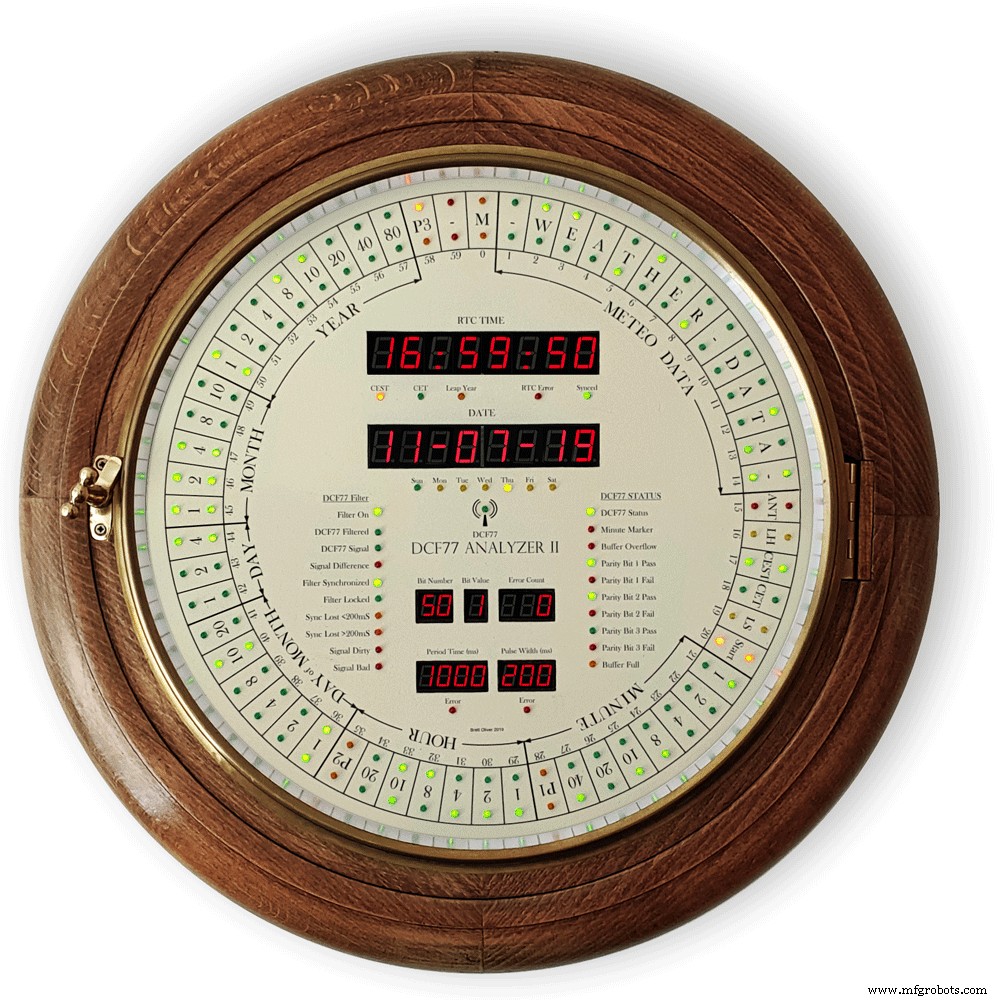
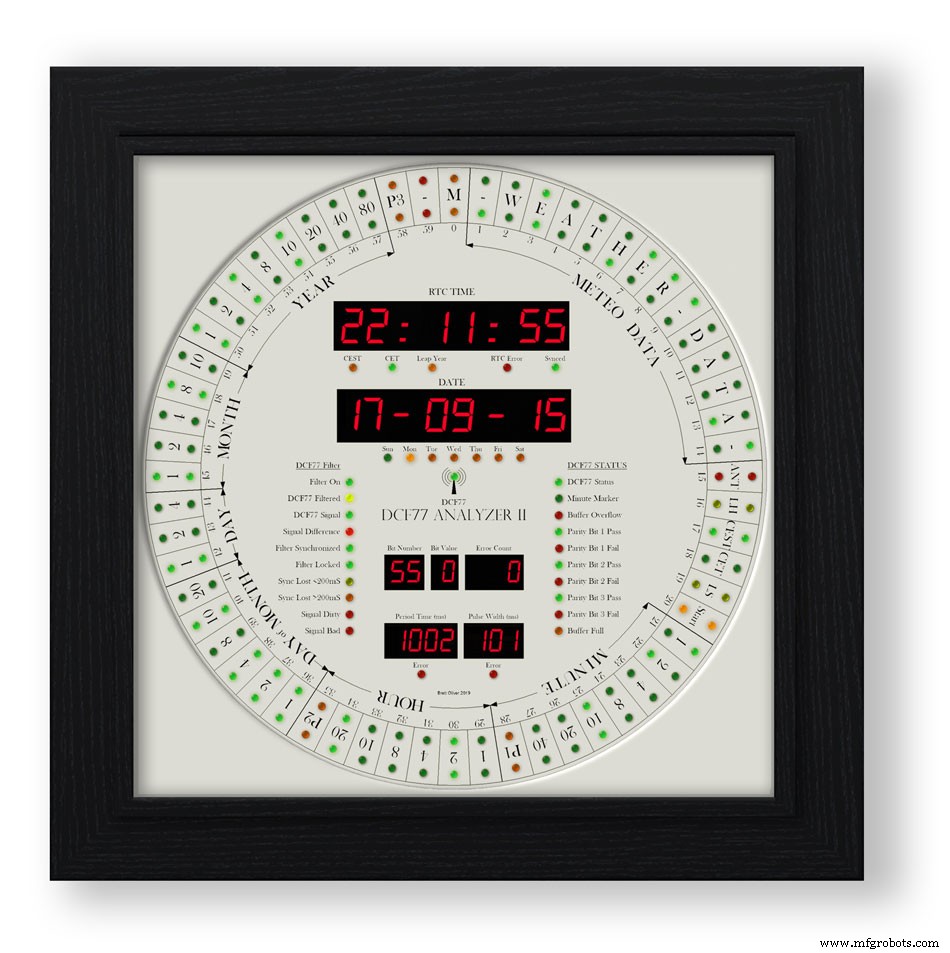
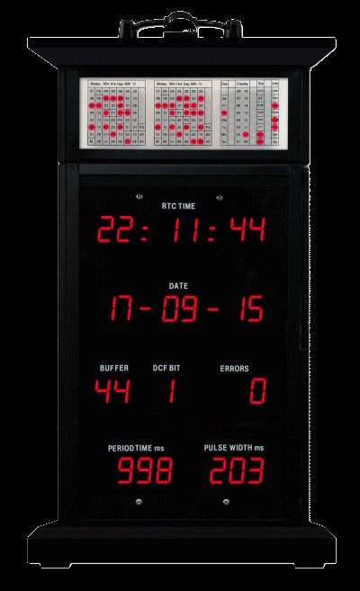
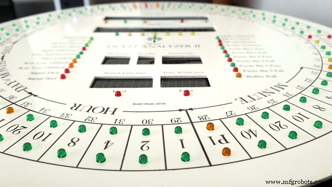
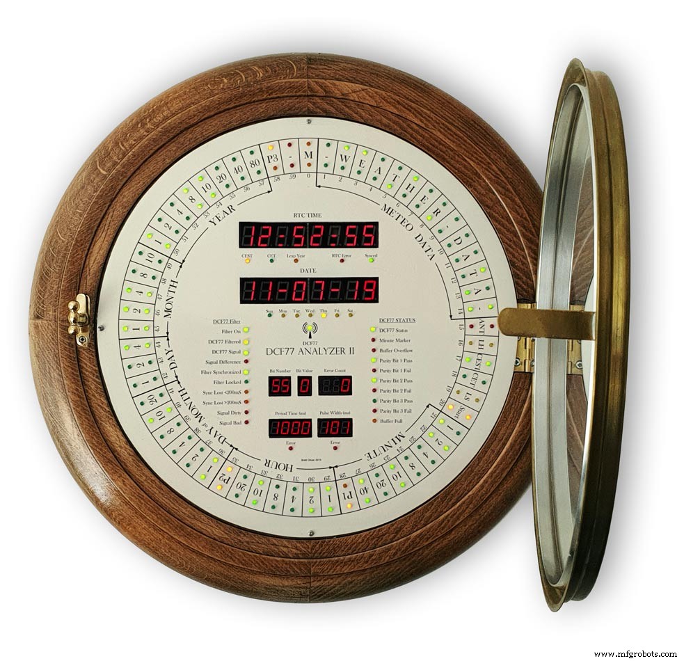
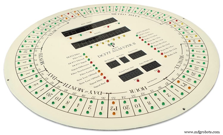
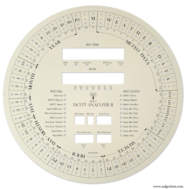
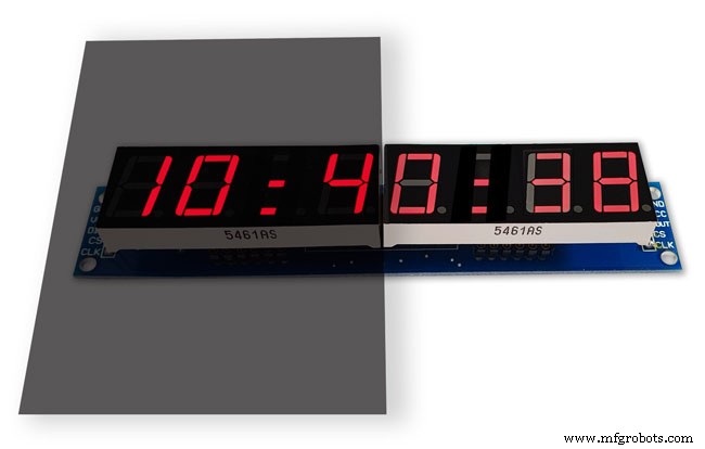
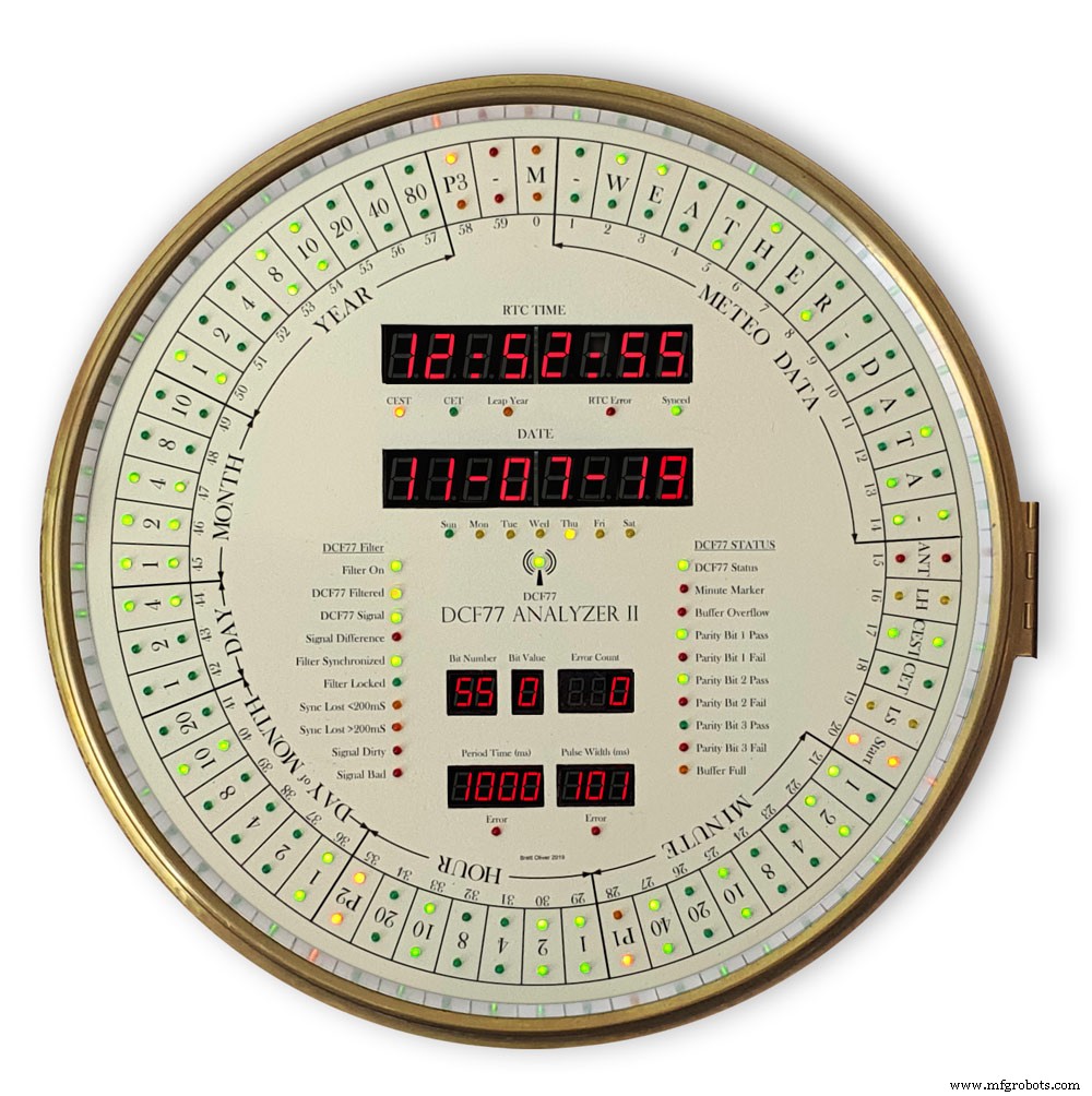
이 시계는 12"(305mm) 직경의 대형 다이얼에 있는 60개의 LED 링 2개에 DCF77 시간 코드를 표시합니다. 내부 링은 수신되는 다음 분의 실시간 시간 코드를 표시하고 외부 링은 현재 시간을 길게 표시합니다. 이전 1분이 오류 없이 수신되었기 때문입니다.
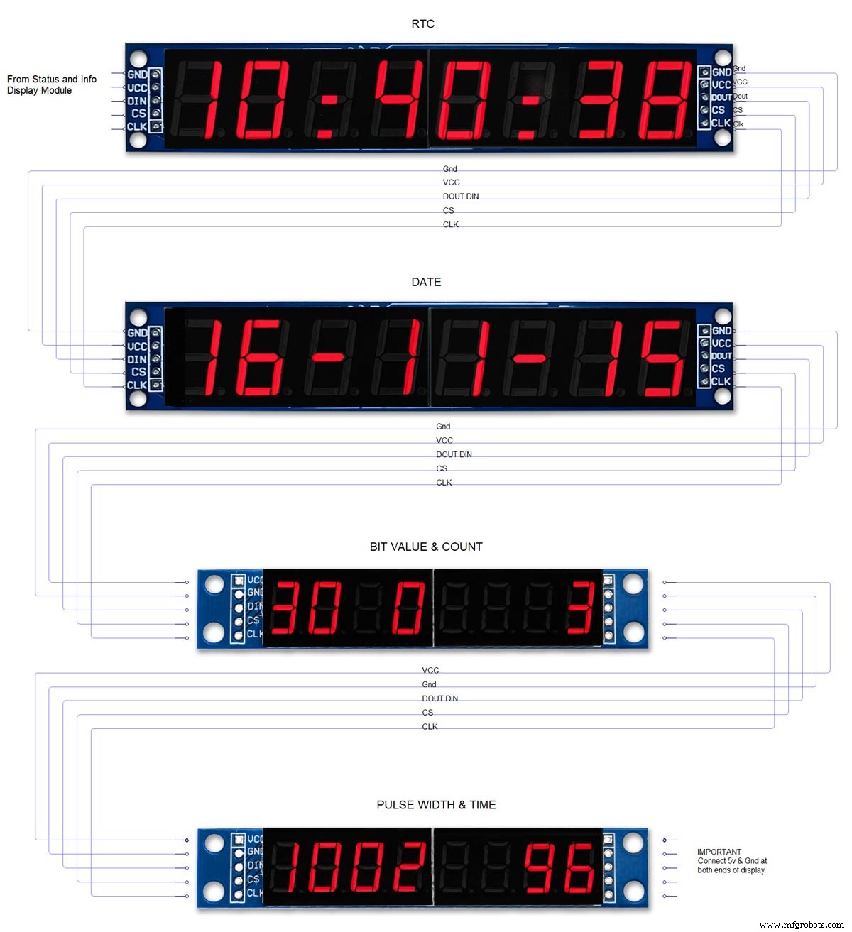
추가 24개의 LED는 디코더 상태 및 시간 정보를 표시합니다. 디코딩된 시간과 날짜는 2개의 큰 8자리 7세그먼트 디스플레이에 표시되고 DCF77 펄스 타이밍 및 비트 정보는 2개의 작은 8자리 7세그먼트 디스플레이에 표시됩니다.
시계는 2개의 Atmega 328 마이크로프로세서(Arduino Uno)를 사용하며, 1개는 DCF77 분석기를 제어하고 1개는 Udo Klein 슈퍼 필터를 제어합니다. 슈퍼 필터는 고급 DCF77 신호 처리와 Arduino 수정 결정의 튜닝을 가능하게 합니다. 필터는 전환 가능하며 10개의 상태 LED가 있어 신호 수신 상태와 출력 품질을 표시합니다. 시계는 또한 2개의 꺼진 JQ6500 사운드 모듈을 통해 시, 1/4시 및 초를 울립니다.
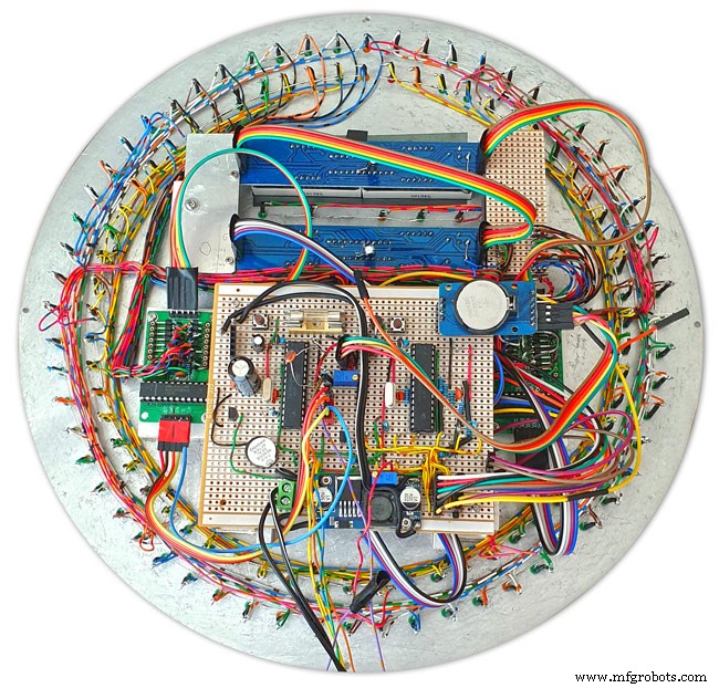
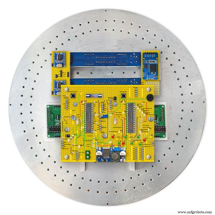
대부분의 전자 장치는 다이얼 뒷면에 장착되어 있어 시계를 다양한 케이스 스타일에 맞출 수 있습니다.
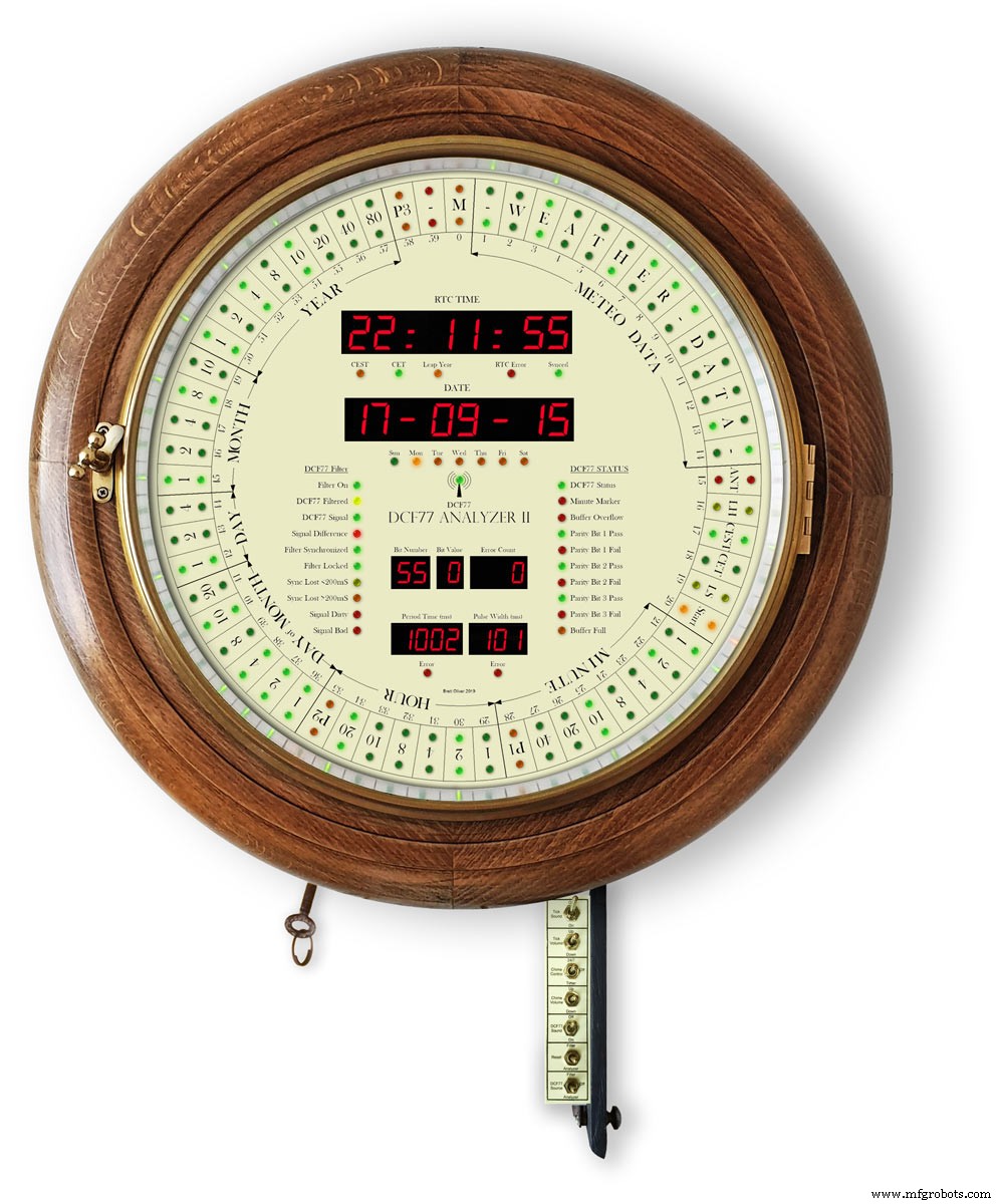
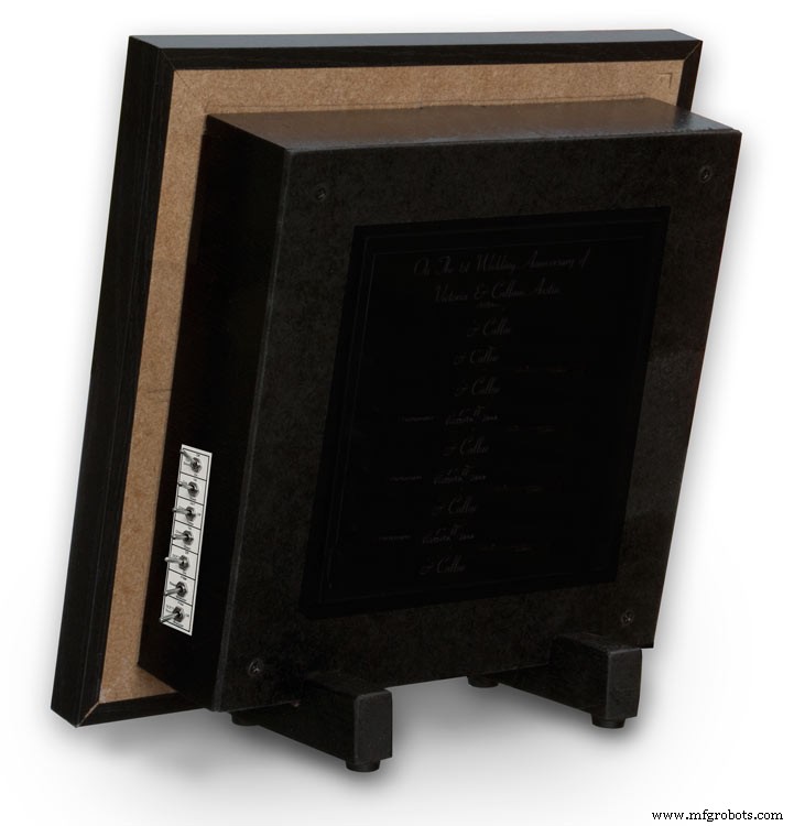
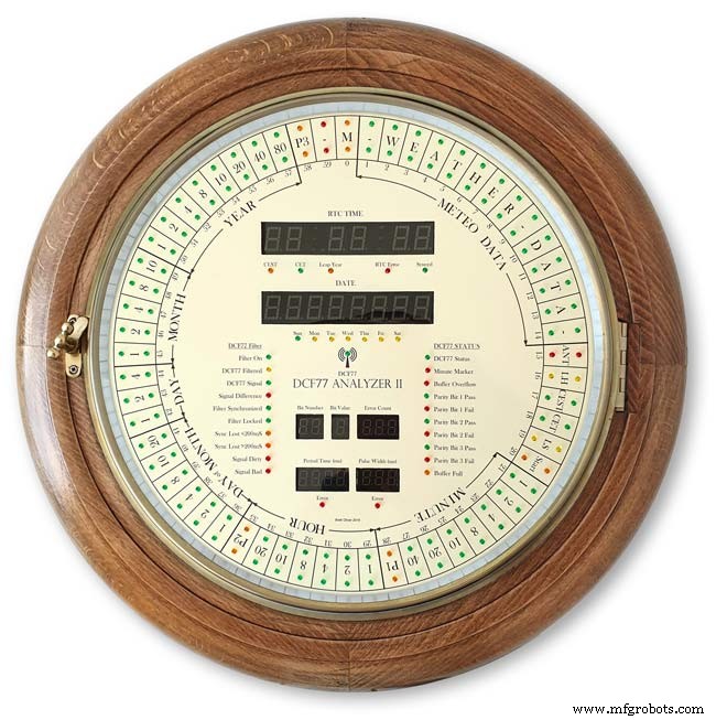
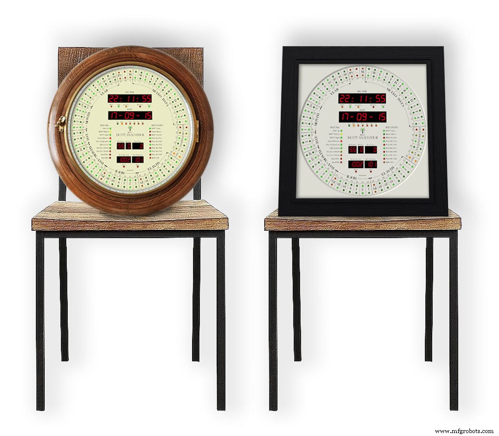
레트로하고 모던한 스타일의 시계 케이스 디자인을 담았습니다. 레트로 디자인은 오래된 다이얼 시계 케이스에, 모던한 디자인은 블랙 액자에 딱 맞습니다.
1단계:크레딧
이 시계는 Erik de Ruiter의 DCF77 분석기 시계를 기반으로 하며 제 Mk1 DCF77 분석기 시계의 업데이트 버전입니다.
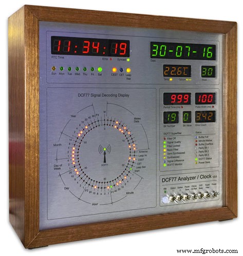
Erik de Ruiter의 DCF77 분석기 시계 위 내 MK1 DCF77 분석기 시계 아래
Erik은 GitHub에서 자신의 시계에 대한 전체 세부정보를 제공했습니다.
에릭의 시계와 내 시계의 차이점
Eric의 시계를 기반으로 하지만 하드웨어를 약간 변경했습니다. 필요에 맞는 옵션을 혼합하여 일치시키되 코드를 적합하게 변경해야 합니다.
나는 Uno와 Mega가 아닌 Veroboard에서 두 개의 맞춤형 Arduino Uno를 사용합니다.
저는 중국 전역에서 저렴한 7세그먼트 디스플레이와 도트 매트릭스 모듈을 사용하고 이에 맞게 코드를 변경했습니다. 이러한 모드가 수행되면 디스플레이 오류가 제대로 작동하므로 섹션을 참조하십시오.
Adafruit 사운드 보드 대신 2x JQ6500 모듈을 사용합니다. 내 보드 중 하나가 소프트웨어로 제어되므로 일부 소프트웨어 변경 사항과 로드할 다른 라이브러리가 있습니다.
Arduino Mega 대신 Arduino Uno가 있으므로 디코더 LED를 구동하기 위한 모든 예비 핀이 없으므로 대신 세 번째 도트 매트릭스 모듈을 사용합니다.
나는 여분의 staus LED를 추가하여 Udo Klein의 Super Filter를 수정했습니다. 이 LED의 밝기는 Super Filter Uno가 아닌 2개의 트랜지스터를 통해 DCF77 디코더 Uno에 의해 제어되는 PWM입니다.
DCF77 디코더 테스트 기능과 일치하도록 슈퍼 필터에 추가된 LED 테스트 기능도 있습니다.
3mm LED만 사용하고 밝기를 균일하게 유지하기 위해 일치하는 밝기 LED를 선택했습니다.
링/상태 LED, 대형 7세그먼트 디스플레이, 소형 7세그먼트 디스플레이 및 슈퍼 필터 LED가 모두 단일 LDR의 판독값에 따라 사용자 정의 밝기 레벨을 갖도록 소프트웨어에 4개의 개별 강도 레벨을 추가했습니다.
내 시계에 온도 또는 주 번호가 표시되지 않으며 그에 맞게 코드를 수정했습니다.
내 슈퍼 필터에 모니터 LED를 추가하여 내 시계에는 합성 및 합성되지 않은 출력에 대한 옵션만 있습니다. 이것은 Erik의 시계에 따라 모드를 전환하는 옵션이 아닙니다.
내 시계의 DCF77 사운드는 들어오는 0과 1 사이의 차이를 강조하도록 수정되었습니다. 시계가 1을 감지하면 200mS보다 약간 더 긴 소리를 재생합니다.
2단계:동영상
비디오는 똑딱 소리가 나는 상태로 작동하는 시계와 4분의 1 및 시를 울리는 시계를 보여줍니다.
또한 다이얼 레이아웃과 디스플레이 읽기에 대한 정보를 보여줍니다.
동영상 2
전원 켜기, 디스플레이 테스트 및 시간/날짜 디코딩을 보여주는 비디오
동영상 3
Udo Klein Super 필터가 이 시계에서 어떻게 작동하는지 보여주는 비디오
동영상 4
비디오는 똑딱 소리가 나는 상태로 작동하는 액자 시계와 4분의 1 및 시를 울리는 시계를 보여줍니다.
또한 다이얼 레이아웃과 디스플레이 읽기에 대한 정보를 보여줍니다.
동영상 5
이 짧은 비디오는 DCF77 신호를 표시하고 디코딩하는 DCF77 분석기 클록을 보여줍니다. 모든 사운드는 DCF77 라이브 신호에서 벗어났습니다.
3단계:컨트롤
시계는 금속 막대에 장착된 7개의 스위치로 제어됩니다. 스위치는 접근을 위해 시계 아래로 접히는 힌지 도어 내부에 부착되어 있습니다.
액자 버전에서 스위치는 시계 측면의 컷아웃에 장착되어 있습니다.
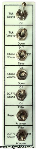
스위치는 다음을 제어합니다.
똑딱 소리 켜기/끄기
틱 볼륨
연중무휴 차임벨 또는 타이머
차임 볼륨
DCF77 사운드 켜기/끄기
슈퍼 필터 또는 분석기 재설정
필터, 끄기 또는 분석기의 DCF77 소스
스위치 기능
똑딱 소리
똑딱 소리를 켜고 끕니다(JQ6500 모듈에서 전원 제거)
볼륨 비잠금 확인
똑딱 소리 볼륨을 높이거나 낮춥니다(똑딱 소리 스위치가 켜져 있어야 함)
차임 컨트롤
끄기 차임벨이 꺼져 있습니다.
24/7 차임벨이 24/7 켜져 있습니다.
타이머 차임벨은 하루 중 정해진 시간에만 켜집니다. 밤에 꺼짐
차임 볼륨 잠금 해제
Up은 볼륨을 높입니다.
Down은 볼륨을 낮춥니다.
각 버튼을 누른 후 새로운 볼륨 설정을 들을 수 있도록 테스트 차임벨이 재생됩니다.
DCF77 사운드
On은 압전 사운더를 통해 수신되는 DCF77 사운드를 비프음으로 재생합니다.
수신된 0과 1을 쉽게 구별할 수 있도록 0은 100mS이고 1은 500mS 비프음으로 재생됩니다.
꺼짐 DCF77 비프음 꺼짐
비잠금 재설정
필터는 DCF77 슈퍼 필터를 재설정하여 DCF77 신호에 다시 동기화합니다.
분석기는 디스플레이 테스트(활성화된 경우)로 시작하여 DCF77 분석기를 재설정한 다음 클록 재동기화를 수행합니다. RTC 시간은 실시간 시계에 저장된 시간부터 표시됩니다.
DCF77 소스
끄기는 클록에서 DCF77 신호 연결을 끊습니다.
분석기 DCF77 신호는 필터링 없이 클록에 직접 공급됩니다.
DCF77 신호를 필터링하여 슈퍼 필터에서 가져오고 슈퍼 필터가 동기화되면 이 신호는 오류가 없는 올바른 신호로 합성됩니다.
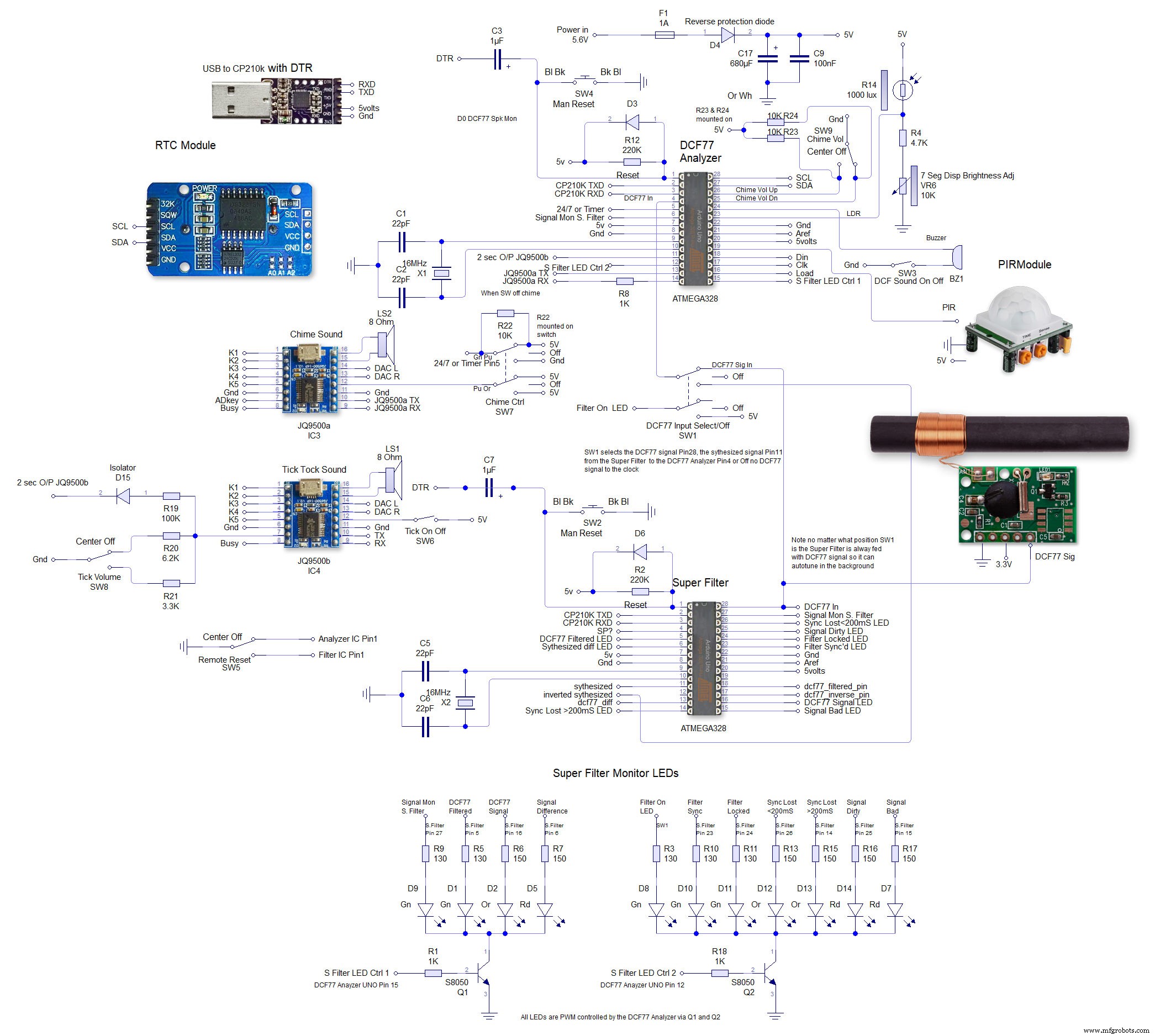
4단계:회로도
이 시계에는 3개의 회로도가 있습니다. 메인 보드, 도트 매트릭스 모듈 및 7세그먼트 디스플레이 모듈.
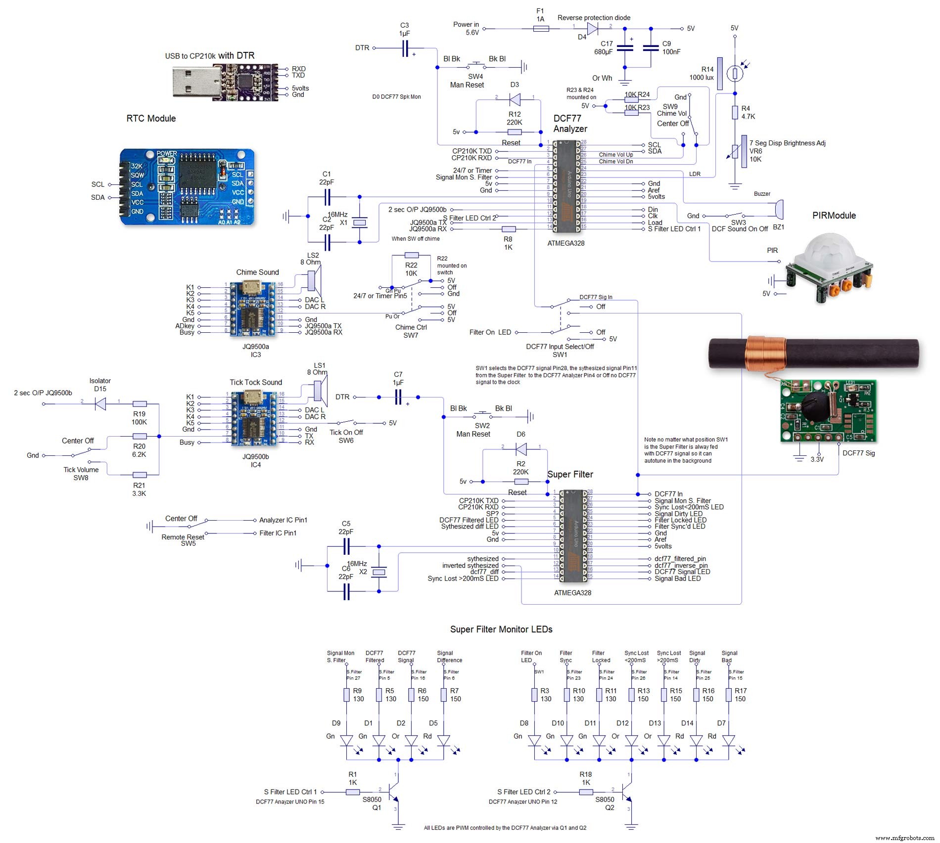
두 번째는 4000x4000 회로도에 대해 매우 크며 여기에서 전체 크기로 볼 수 있습니다. 배선하기 쉽도록 이렇게 배치했습니다.

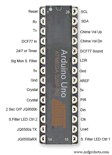
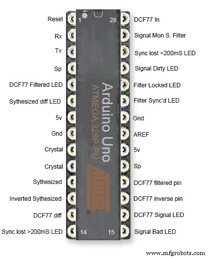
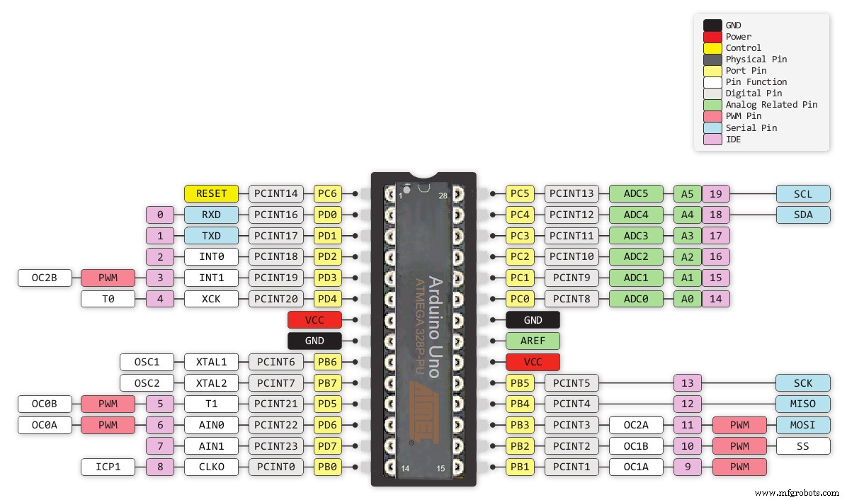
5단계:Atmega 핀 연결
이 시계는 맞춤형 vero 보드에서 2개의 Atmega 328 IC를 사용합니다. 시계의 분석기 부분에는 표준 UNO를 사용할 수 있지만 시계의 슈퍼 필터 부분에는 공진기보다 수정 결정이 있는 UNO를 사용해야 합니다. 여기에서 Arduino UNO에 수정을 추가하는 방법을 확인하십시오. http://www.brettoliver.org.uk/Master_Clock_MK2/Master_Clock_MK2.htm#Mod
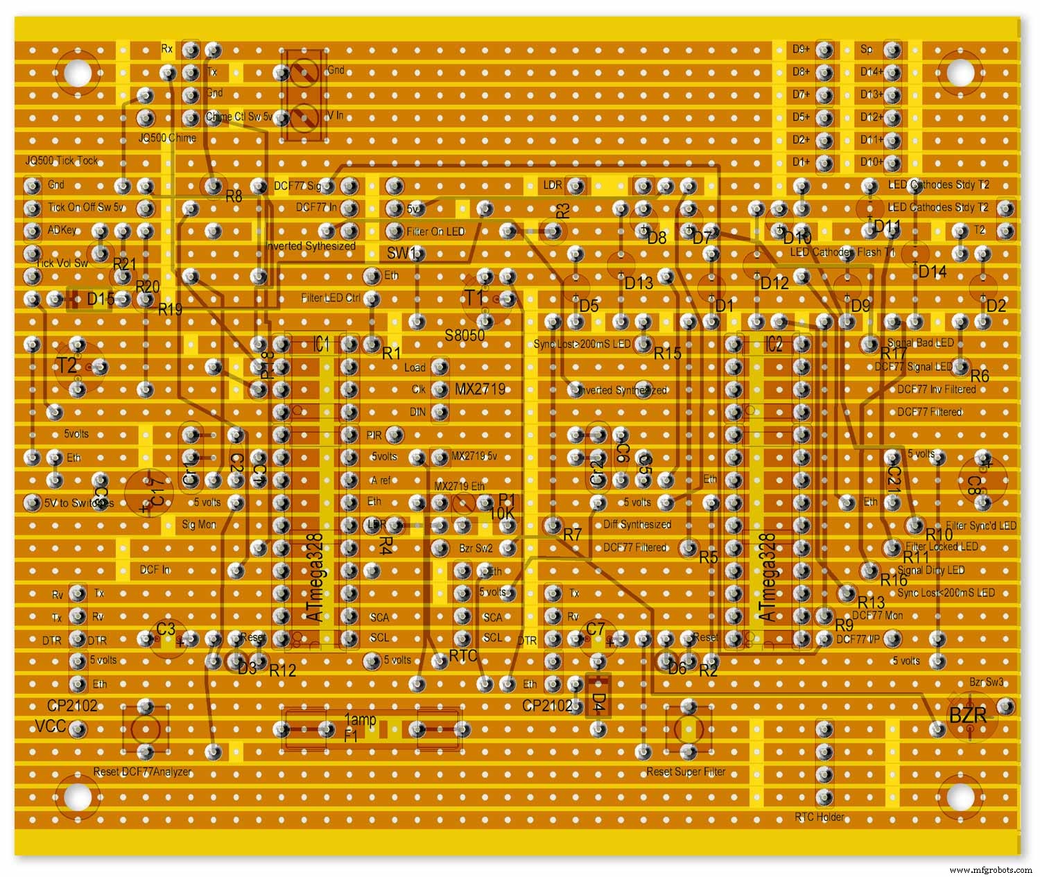
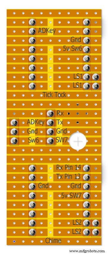
6단계:Vero 보드 레이아웃
이 프로젝트를 위한 많은 모듈이 미리 빌드되어 있고 꽂기만 하면 되지만 Arduinos용 메인 보드, 사운드 모듈 및 3차 LED 매트릭스는 Vero 보드에 빌드해야 합니다.
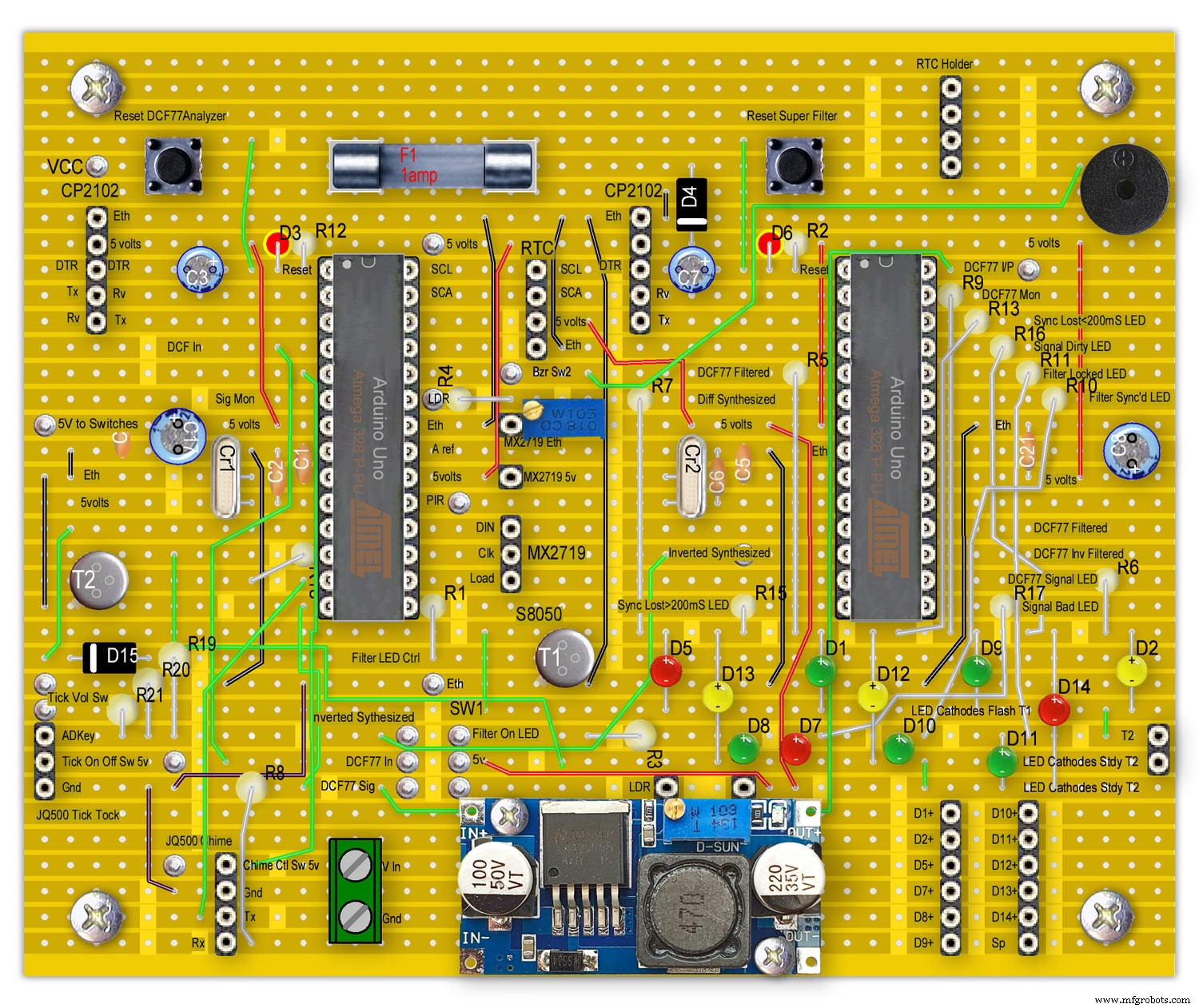
LED는 참고용으로만 메인 보드에 장착된 것으로 표시됩니다.
메인 보드에서 다른 보드로의 모든 배선은 PCB 헤더 커넥터를 통해 이루어집니다. 메인 보드에서 스위치 패널로의 연결은 직접 배선됩니다. 이를 통해 메인보드와 스위치 패널을 제거하여 유지보수할 수 있습니다.
이것들은 Arduino UNO로 구성되며 사전 빌드된 Unos 또는 Nanoscould를 사용할 수 있지만 Super Filter Arduino는 정확도를 위해 공진기가 아닌 수정을 가져야 합니다. 위의 Atmega 핀 연결을 참조하십시오.
내 마스터 시계 사이트 Arduino 수정 수정에 대한 정보 보기

참고 RTC는 여기에 장착되지만 헤더 케이블로만 연결됩니다.
7단계:사전 구축된 모듈
사전 제작된 보드 및 모듈
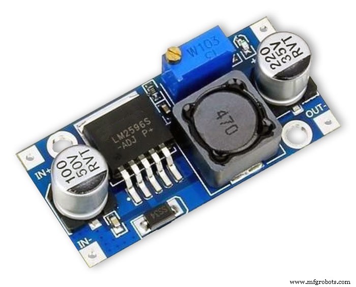
LM2596 레귤레이터 모듈은 전압을 5v로 낮춥니다. 이것은 모듈의 10K 사전 설정 저항에 의해 조정되고 역방향 보호 다이오드 D4 이후에 측정됩니다. Arduinos를 보드에 추가하기 전에 이것을 조정하십시오.
시계는 최대 밝기에서 LED를 사용하여 최대 약 450mA를 사용하고 디스플레이를 끄면 약 80mA로 떨어집니다.
7-12볼트의 1000mA DC PSU로 안전해야 합니다(LM2596 레귤레이터 모듈이 전압을 제어함)
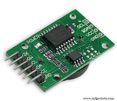
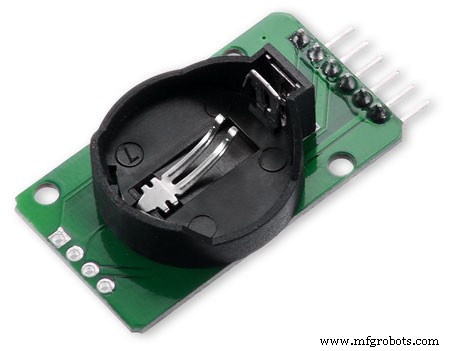
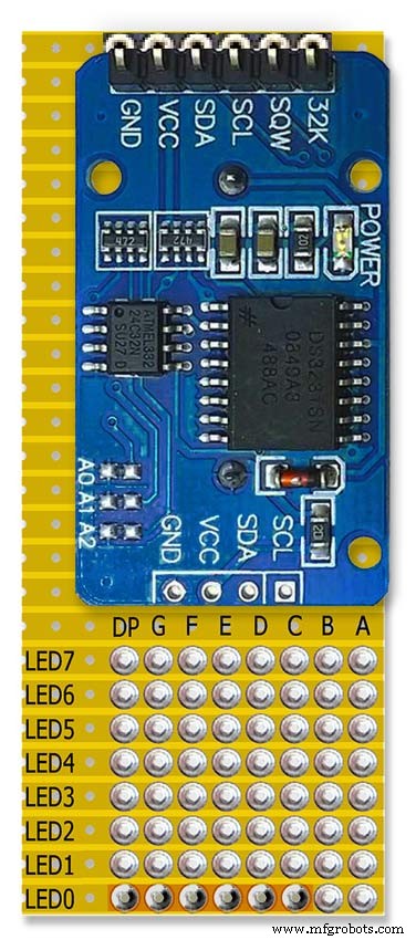
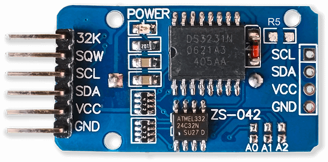
RTC DS3231 I2C 이 모듈은 디코딩된 DCF77 신호의 시간을 저장합니다. 내장 시계에는 온도 보상 기능이 있으며 정전 시 배터리 백업 기능이 있습니다. RTC 모듈은 비충전식 배터리를 사용하도록 수정되었습니다.
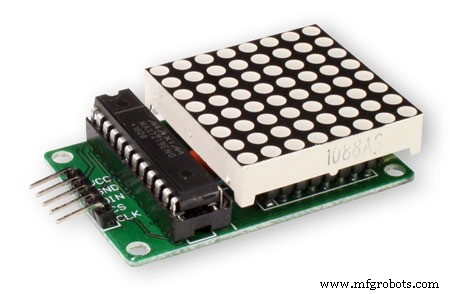
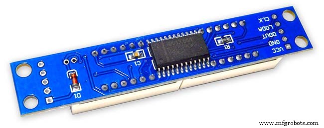
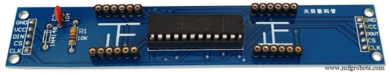
MAX2719 도트 매트릭스 모듈이 모듈은 내부 및 외부 LED 링(2개 모듈)을 구동하고 세 번째 모듈은 슈퍼 필터 LED를 제외한 다른 모든 LED를 구동합니다. LED 매트릭스가 제거되고 PCB 헤더가 제자리에 납땜됩니다.
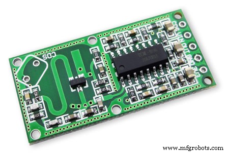
RCWL 0516 Doppler Radar Sensor Microwave방에 사람이 있을 때만 시계 표시를 켜려면 움직임 감지를 사용합니다. 유리 뒤에서 움직임을 감지하는 아래의 RCWL 0516 또는 아래의 PIR 모듈 중에서 선택할 수 있습니다.
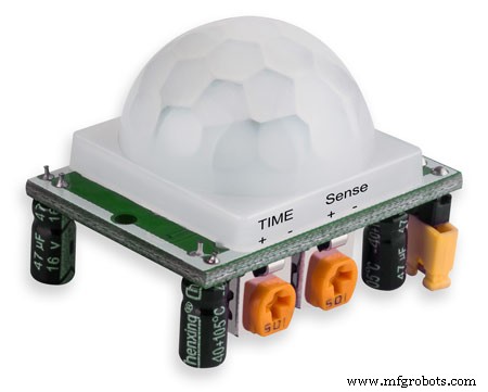
PIR 모듈 적외선위의 도플러 레이더 센서 대신 PIR 모듈을 사용할 수 있습니다. 이 장치의 단점은 유리나 perspex 등 뒤에 사용할 수 없다는 것입니다.

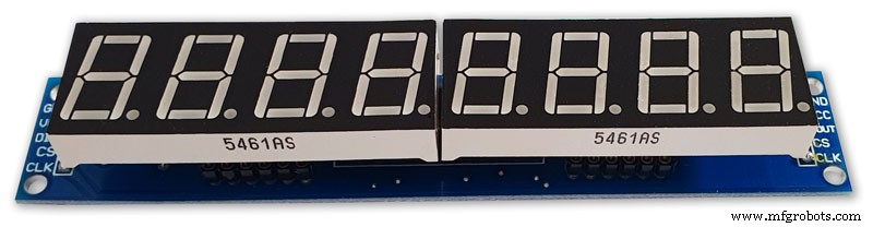
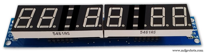
Max2719 7 세그먼트 디스플레이 0.56"이것은 시간 및 날짜 디스플레이에 사용되는 더 큰 0.56" 버전입니다. 나는 이미 이것들의 배치를 가지고 있지만 tindie에 유사한 모듈이 있습니다. 0.56" 디스플레이가 더 큰지 확인하십시오. 이러한 모듈의 디스플레이 오류를 방지하려면 약간의 수정이 필요할 수 있습니다. MAX2719 수정 단계를 참조하십시오.
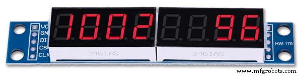
Max2719 7 세그먼트 디스플레이 0.39"비트, 오류 및 펄스 디스플레이에 사용되는 더 작은 0.39" 버전입니다. 그들은 eBay와 Amazon에서 모두 사용할 수 있습니다. 헤더 핀이 납땜되지 않은 모듈이나 모듈 뒷면에 납땜된 핀이 있는 보드만 있으면 됩니다. 이러한 모듈의 표시 오류를 방지하기 위해 약간의 수정이 필요할 수 있습니다. MAX2719 수정 단계를 참조하십시오.

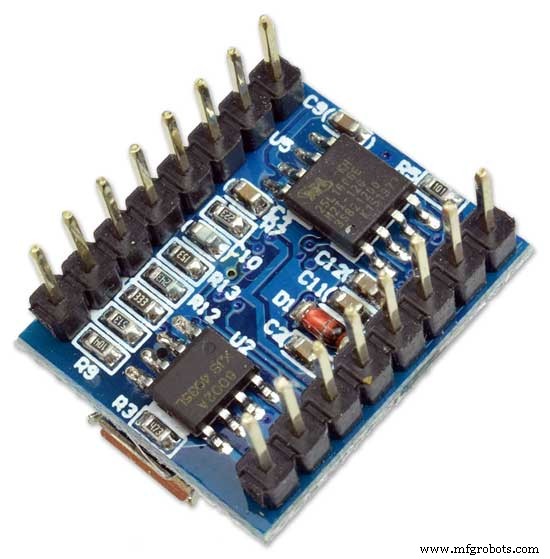
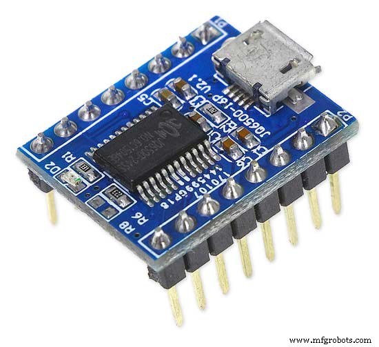
JQ6500 16p 모듈이 모듈 중 하나는 똑딱 소리를 재생하고 다른 분기 및 시간 차임을 재생하는 데 사용됩니다. 프로젝트에 포함된 사운드 파일을 사용하면 2M 메모리가 있는 가장 저렴한 16p 모듈을 사용할 수 있습니다. 모듈은 각각 단일 3W 8Ω 스피커를 구동합니다. 간단한 프로그램을 사용하여 USB를 통해 PC(MAC 아님)에서 사운드를 로드합니다.
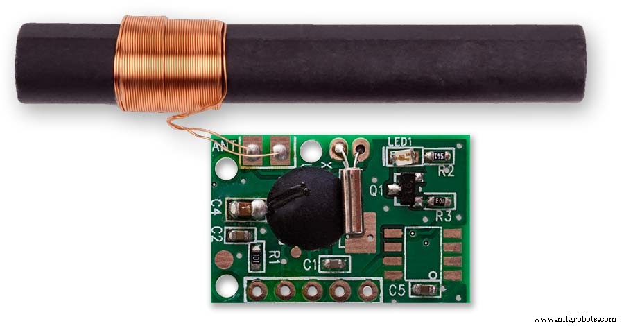
DCF77 수신기
http://www.pvelectronics.co.uk
의 내 DCF77 수신기 모듈이 항목은 더 이상 사용할 수 없는 것 같지만 Amazon을 사용해 보세요.
PV Electronics DCF77 수신기 모듈 연결 왼쪽에서 오른쪽으로 연결
1.VDD 2.TCON 3.PON 4.GND 5.NC
반전된 형식으로 출력을 제공합니다(출력은 낮고 초당 한 번 높음).
저전력 대기 모드 - PON을 Vdd에 연결합니다.
정상 작동을 위해 PON을 GND에 연결합니다.
수신기를 TV, 모니터 또는 기타 전기 노이즈로부터 멀리 유지하고 DFC77 송신기를 가리키는지 확인하십시오.
구성 요소
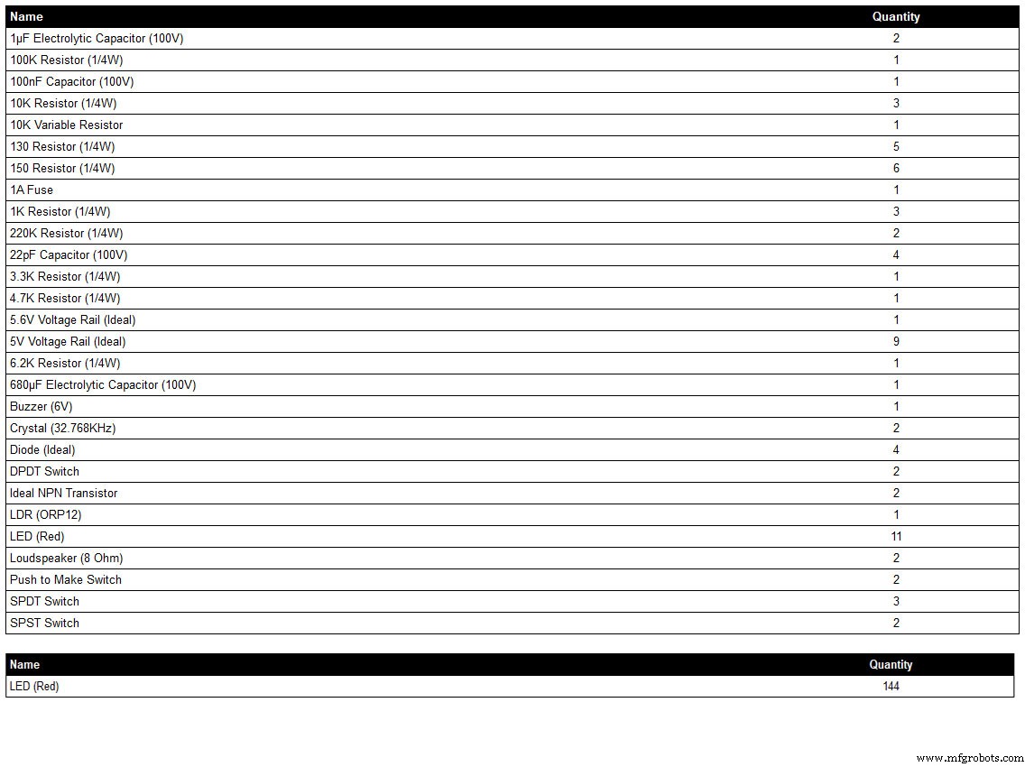
구성 요소 목록은 내 회로도 그리기 프로그램 LiveWire에서 생성되므로 구성 요소가 프로그램 라이브러리(예:일부 스위치)에 없는 경우 전체 세부 정보가 표시되지 않을 수 있습니다. 자세한 내용은 회로도를 확인하거나 저에게 연락하십시오.
LED 색상은 필요에 따라 선택할 수 있지만 실제로 사용한 LED는 LED 섹션을 참조하세요.
8단계:배선 순서
배선 연결을 위한 약 400개의 홀수 와이어가 있으므로 모듈 사이의 간격에 배선 실행을 맞추기 위해 많은 계획이 필요합니다.
필요한 경우 수정하고 모든 보드를 다이얼 뒤쪽에 고정하여 배선 하니스가 보이도록 합니다.
도트 매트릭스 보드가 제거되고 시계에서 떨어져 배선됩니다.
슈퍼 필터 LED를 배선하고 다이얼에 맞춥니다.
DCF77 상태 LED를 배선하고 다이얼에 맞춥니다.
수퍼 필터 및 DCF77 상태 LED는 헤더 케이블을 통해 메인 보드에 연결됩니다. 도트 매트릭스 모듈 3의 모든 LED를 배선하고 다이얼에 맞춥니다.
도트 매트릭스 모듈 3에서 소형 브레이크아웃 베로 보드로 배선한 다음 위의 단계에서 장착된 이 모듈의 LED에 배선합니다.
외부 LED 링을 배선한 다음 다이얼에 맞춥니다.
외부 링 LED에서 종료할 수 있을 만큼 충분히 긴 와이어 끝을 남기고 외부 링 도트 매트릭스 디스플레이를 배선합니다.
외부 링 도트 매트릭스 디스플레이를 다시 장착하고 와이어링 하니스를 외부 링 LED에 종단합니다.
내부 LED 링을 배선한 다음 다이얼에 맞춥니다.
내부 링 LED에서 끝나는 와이어 끝을 충분히 길게 남겨두고 내부 링 도트 매트릭스 디스플레이를 배선합니다.
내부 링 도트 매트릭스 디스플레이를 다시 장착하고 와이어링 하니스를 내부 링 LED에 종단합니다.
도트 매트릭스 모듈 3의 모든 LED를 배선하고 다이얼에 맞춥니다.
도트 매트릭스 모듈 3에서 소형 브레이크아웃 베로 보드로 배선한 다음 위의 단계에서 장착된 이 모듈의 LED에 배선합니다.
헤더 케이블을 만들고 모든 보드에 연결합니다.
메인 Vero 보드를 장착한 다음 스위치 패널에 배선합니다. LDR은 스위치 패널이 고정되어 있는 힌지 목제 도어를 통해 장착되어 동시에 배선됩니다.
스피커를 장착하고 JQ6500 사운드 모듈을 사용하여 Vero 보드에 연결합니다.
다이얼에 정확한 크기의 구멍을 뚫었다면 모든 LED가 접착제 없이 제자리에 끼워질 것입니다. LED 구멍의 안쪽 가장자리는 마찰 끼워맞춤에 도움이 되도록 페인팅 단계에서 페인트/바니시로 코팅되었는지 확인하십시오.
9단계:Max2719 도트 매트릭스 모듈 수정 배선
와이어를 MAX 2917 매트릭스 모듈에 연결하려면 먼저 와이어를 수정해야 합니다.
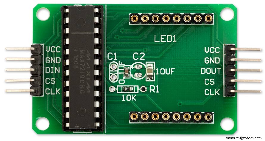
도트 매트릭스 LED는 필요하지 않으므로 제거하십시오.
8개의 90° 핀 커넥터 2세트가 기존 LED 매트릭스 커넥터의 아래쪽 가장자리에 납땜됩니다.
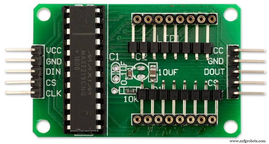
기존 LED 매트릭스 커넥터의 바닥에 납땜된 90° 핀 커넥터가 있는 수정된 MAX7219 모듈. 와이어는 이 지점에서 메인 보드의 LED 매트릭스로 제거됩니다.
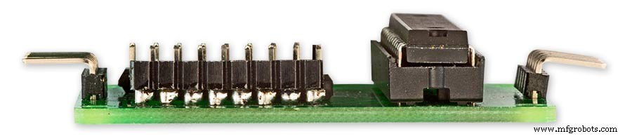
PCB 바로 위의 기존 LED Matrix 커넥터 핀의 측면에 납땜된 핀을 보여주는 측면도입니다.
10단계:배선 배선 지그 만들기
지그는 LED를 올바른 간격으로 제자리에 고정하여 시계에서 쉽게 배선할 수 있도록 합니다.
LED 배선 지그 제작
다이얼을 종이에 인쇄하십시오. 시계 뒤에서 작업하므로 거꾸로 인쇄하거나 용지를 뒤로 눕힙니다. 오래된 나무 조각이나 멜라민 위에 시트를 놓으십시오. 모든 LED 센터를 센터 펀치하고 3mm 드릴 비트로 드릴하십시오. 구멍은 쉬운 배선을 보장하기 위해 LED에 마찰 맞춤되어야 합니다. LED는 직경이 다르므로 먼저 몇 가지 테스트 구멍을 수행하여 LED에 맞는 크기를 확인하십시오.
배선 지그 완성.
지그의 내부 및 외부 LED 링을 완성했습니다. LED 번호와 기타 정보를 지그에 기록하면 LED가 다이얼 뒤쪽에 장착되어 있고 시계 반대 방향으로 뒤집혀 있기 때문에 올바른 LED를 배선했는지 확인하는 것이 편리할 수 있습니다.
다이얼에 삽입할 준비가 된 지그에서 제거된 LED 링.
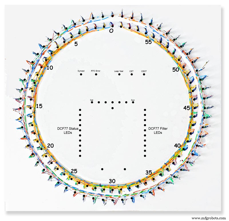
11단계:LED 내부 및 외부 링 배선
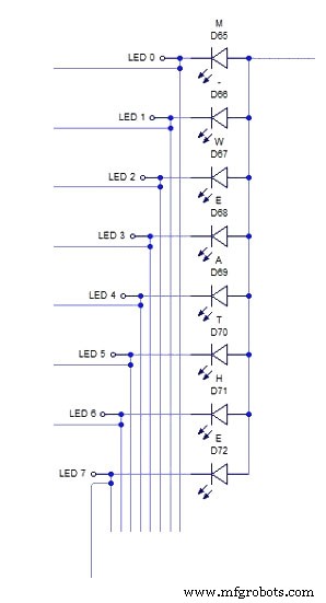
위의 개략도는 외부 LED 링의 8개 LED 섹션에 대한 배선을 보여줍니다.
먼저 8개의 LED를 지그의 구멍에 밀어 넣습니다. 모든 양극을 구부려 시매틱에 따라 함께 연결하고 제자리에 납땜합니다. 와이어는 나중에 LED 매트릭스 모듈에서 연결된 8개의 양극에 연결됩니다. 음극 위에 절연 슬리브를 약간 끼운 다음 LED에서 이 다리를 약 15mm 구부립니다. 구부러진 부분에서 약 5mm를 자르고 8개 LED의 다음 배치에 도달할 만큼 충분히 긴 짧은 길이의 와이어를 납땜합니다. pic2를 참조하십시오.
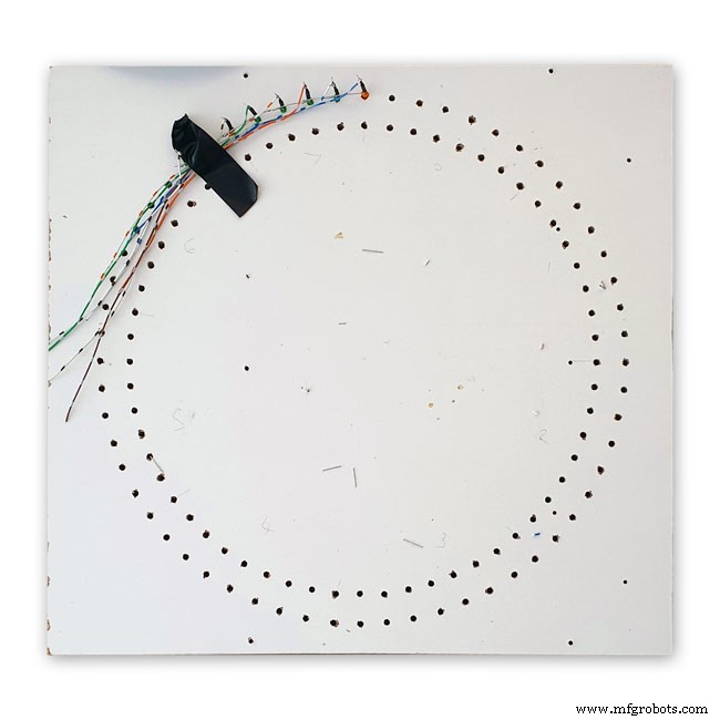
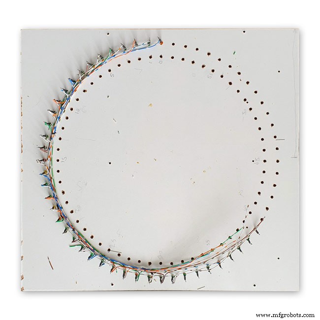
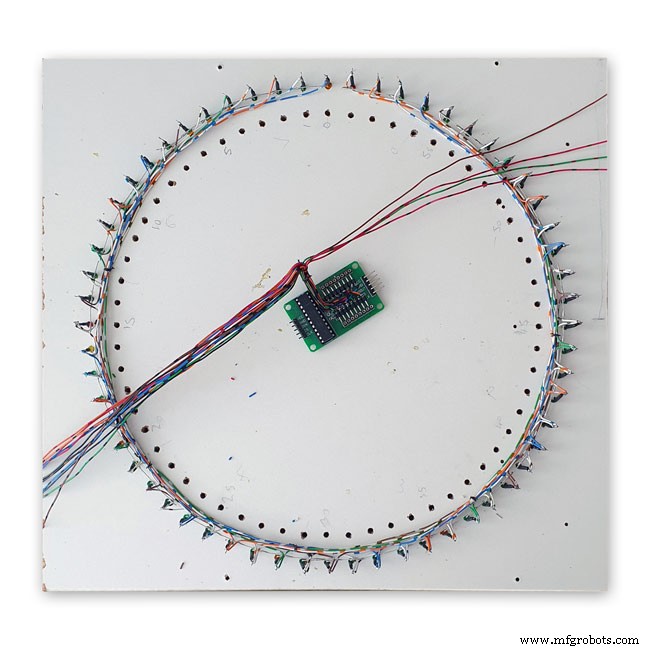
그림 1 이것은 8개의 LED의 다음 섹션으로 이어지는 와이어와 함께 지그에 배선된 8개의 LED의 완성된 섹션을 보여줍니다.
그림 2 8개의 LED 배치로 위의 과정을 반복합니다.
8개 LED의 각 배치에는 도트 매트릭스 모듈에 대한 자체 별도의 양극 연결이 있습니다. 총 8개.
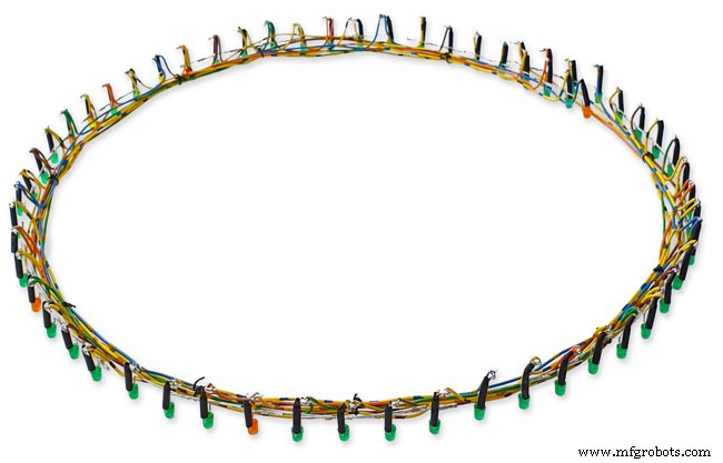
그림 3 도트 매트릭스 디스플레이에 연결된 16개의 전선과 함께 완성된 외부 링 LED.
그런 다음 LED를 다이얼의 구멍으로 밀어넣고 매트릭스 모듈을 다이얼에 다시 고정합니다. 제자리에 배치되면 도트 매트릭스 모듈의 16개 와이어가 외부 링 LED에 연결됩니다. 이 과정은 내부 LED 링에 대해 반복됩니다.
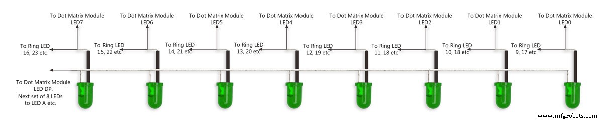
도트 매트릭스 모듈의 16개 와이어는 8개 LED 섹션의 8개 세트에 걸쳐 연결할 준비가 되어 있습니다. 8번째 세트에는 4개의 LED만 있습니다. 전체 크기의 4000x4000 회로도는 여기에서 볼 수 있습니다.
LED
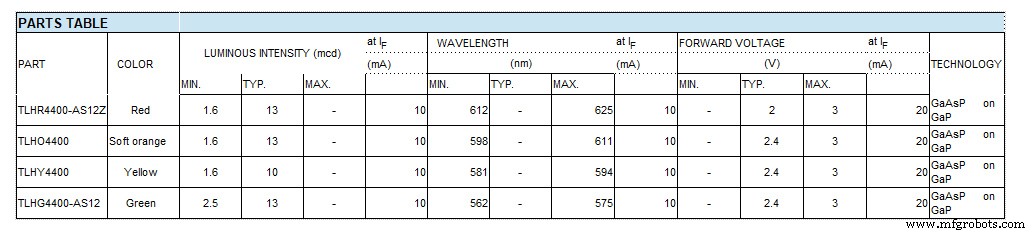
저는 Vishay TLH44 시리즈 고효율 LED를 Ø 3mm 착색 확산 패키지로 사용했습니다.
설명 TLH.44.. 시리즈는 일반 표시 및 조명 목적과 같은 표준 애플리케이션을 위해 개발되었습니다. 3mm 착색된 확산 플라스틱 패키지에 들어 있습니다. 이러한 장치의 넓은 시야각은 높은 온오프 대비를 제공합니다.
광도가 다른 여러 선택 유형이 제공됩니다. 모든 LED는 광도 그룹으로 분류됩니다. 이를 통해 사용자는 균일한 모양의 LED를 조립할 수 있습니다.
기능
• 표준 Ø 3mm(T-1) 패키지
• 작은 기계적 공차
• DC 및 높은 피크 전류에 적합
• 넓은 시야각
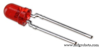
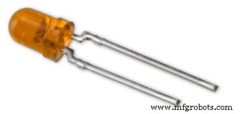
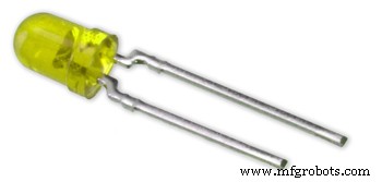
위의 그림 1-4는 실제 부품 번호가 있는 차트를 보여주는 아래 그림과 함께 LED 색상을 보여줍니다.
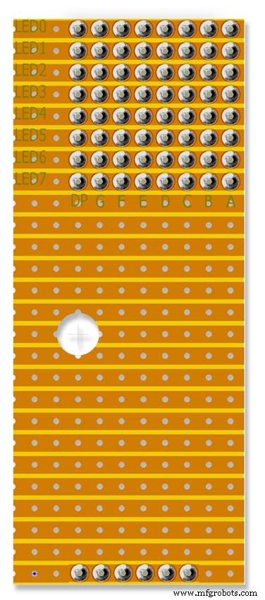
12:세 번째 도트 매트릭스 모듈 배선
세 번째 도트 매트릭스 모듈 배선
이 모듈에는 64개의 LED 중 24개의 LED만 연결되어 있습니다.
8개의 LED 중 첫 번째 섹션의 요일 LED(7개만 연결됨)
8개의 LED 중 두 번째는 CEST, CET Leap Yr, RTC 오류, 동기화됨, 오류 기간 및 오류 펄스 폭(7개만 연결됨)
8개 LED 중 3번째는 버퍼 가득 참, 패리티 3 대 1 통과 및 실패 및 버퍼 Oveflow(8개 LED 모두 연결됨)
8개 LED 중 4번째 LED에는 2개의 LED 분 마커 및 DCF77 상태만 포함되어 있습니다.
8개의 LED를 3세트만 사용해도 되지만 4세트를 사용하면 배선이 간단해집니다.
이 LED는 배선 지그에 배선된 다음 매트릭스 배선에 연결된 작은 Vero 보드에 연결됩니다. 이 보드는 RTC의 마운트 역할도 합니다.
13단계:스위치 패널 배선

스위치 패널은 액세스 도어 뒷면에 고정된 시계 아래로 내려갑니다. 배선은 메인 보드에 직접 납땜되며 LDR용 배선이 포함됩니다.

스위치 패널
스위치 패널 배선 진행 중
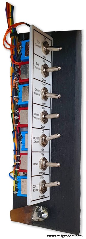
시계 바닥에 있는 도어에 장착된 완성된 배선 직기가 있는 스위치 패널
메인보드에서 아래로 내려오는 스위치용 배선직기로 배선을 완료했습니다. 스위치 패널은 시계 케이스에 접혀 표시됩니다.
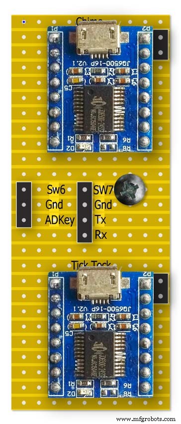
14단계:JQ6500의 차임 및 똑딱 소리

이 시계는 2개의 JQ6500 모듈을 사용합니다. 똑딱 소리는 하드웨어로 제어되고 차임은 소프트웨어로 제어됩니다.
차임 회로
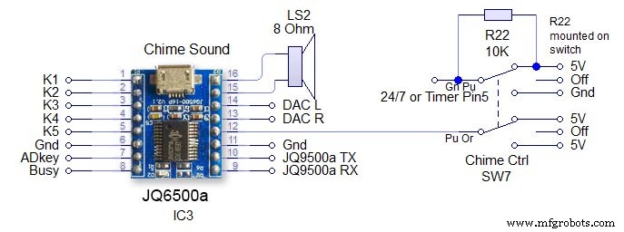
스위치 SW7은 3위치 잠금 스위치입니다. 모듈은 Arduino의 직렬 하드웨어 핀 13 및 14를 통해 제어됩니다. 수신 회로의 1K 저항에 유의하십시오. 주요 회로도를 참조하십시오. 꺼짐 - JQ9500에서 전원이 제거되고 Arduino 핀이 24/7 부동 상태로 유지되는 것을 방지하기 위해 24/7 /timer 핀이 높게 유지됩니다. 시간 차임벨은 05:15~23:00에만 울립니다. (코드에서 설정) 볼륨은 Arduino와 차임 볼륨 업 또는 다운 스위치를 통해 소프트웨어에서 설정됩니다.
틱톡 서킷
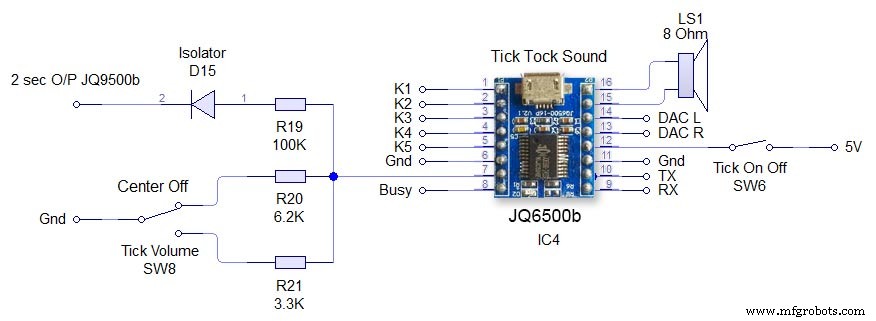
이것은 JQ6500 스위치 SW6 Tick On/Off로 직접 제어되는 하드웨어이며 JQ6500에서 전원을 제거합니다. 틱볼륨 SW8은 3way 중앙 잠금 스위치입니다. 스위치를 위 또는 아래로 조작하면 JQ6500의 ADKey 핀을 통해 볼륨이 설정됩니다. 틱톡 소리를 재생하라는 명령은 Arduino에서 2초마다 도착합니다. 사운드 파일은 2초 미만이어야 합니다. 다이오드 D15는 Arduino 출력에서 ADKey를 분리합니다.
15단계:연사
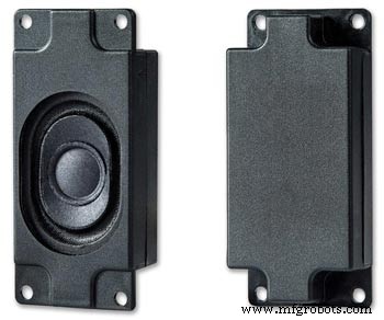
사운드 모듈은 시계 케이스 측면에 부착된 3W 8Ω 스피커에 각각 연결됩니다. Amazon에서 한 쌍으로 구입할 수 있습니다.
이 사진은 시계 케이스의 스피커 위치를 보여줍니다. 시계 하단의 접힌 스위치 제어판을 확인하십시오.
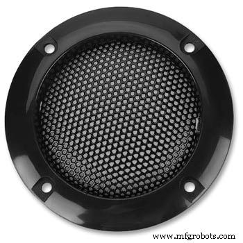
2개의 스피커 그릴이 스피커를 덮고 있으며 아마존에서 가져온 것이기도 합니다.
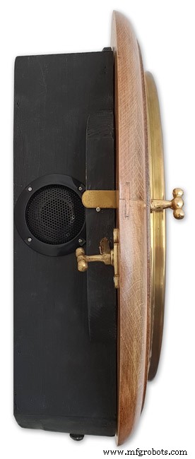
스피커 위치를 보여주는 시계의 왼쪽. 이것은 반대쪽에서도 반복됩니다.
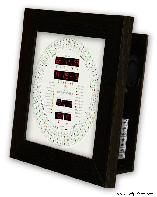
오른쪽 스피커를 보여주는 액자 스타일 시계.
16단계:JQ6500 사운드 파일 로드
사운드를 JQ6500 모듈에 로드해야 합니다.
이 모듈에 대한 정보 및 Arduino 라이브러리는 이 사이트를 참조하십시오.
Arduino 라이브러리 JQ6500_Serial일반 infoJQ6500 도구
일반적으로 JQ6500에는 PC에 연결할 때 로드되는 음악 업로더 프로그램이 사전 로드되어 있습니다(MAC에서는 작동하지 않습니다!). This is in Chinese there are instructions on my site here showing how to use the Chinese version.
My JQ6500s came without a loader program so I downloaded an English version from Nikolai Radke
You can get the zip file from here English Language MusicDownload.exe v1.2a
JQ6500_English_MusicDownload_V1_2a.zipI just run this file from windows (no need to install it) and it runs in English see details below.
Insert your JQ6500 into PC via USB.

When the file is run this window will open. Click FILES
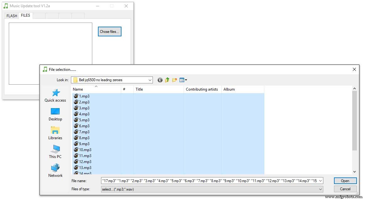
Click CHOSE FILES and shift select all the files you want to be copied to the module. Note make sure your files are named as below.
1 to 12 are the hour chimes. 13 to 16 are the quater chimes and 17 is the test chime used when setting the chime volume using the Chime Volume Switch.
Click OPEN above then click on the FLASH tab.
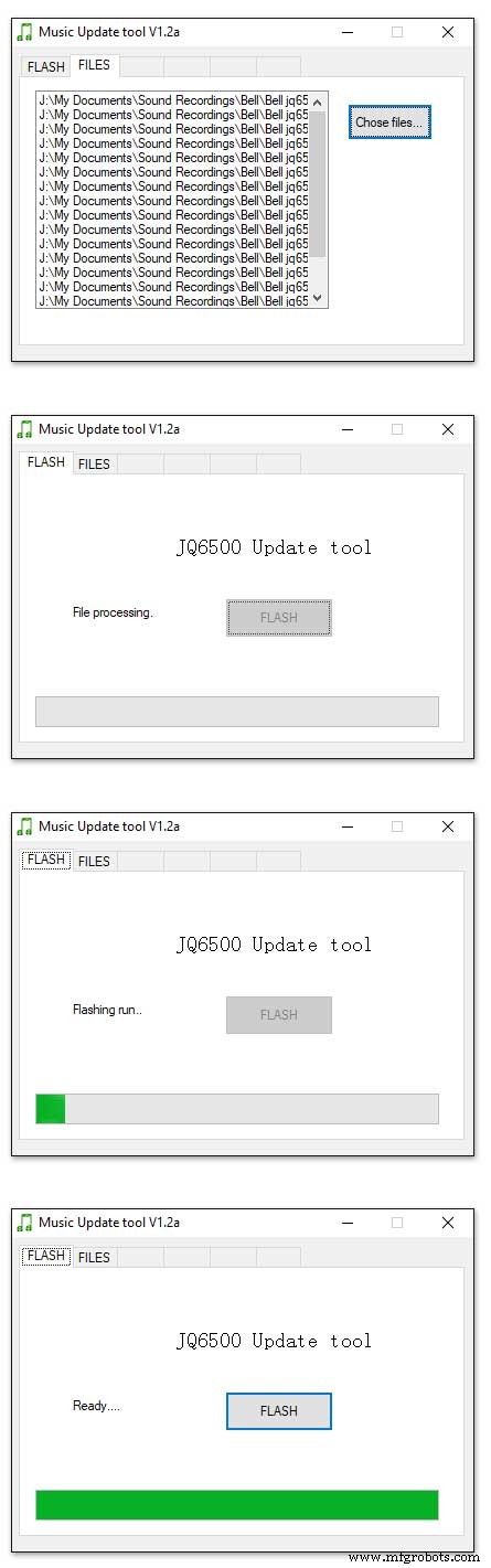
Click on FLASH and you should get a message saying FILE PROCESSING It the files will fit on the module the message will change to FLASHING RUN and a green bar will show progress.
When flashing is completed the message will change to READY......You can remove your module and plug it into sound board on the clock.
Repeat this for the Tick Tock sound (1 file this time) on the 2nd module.
Sound files are enclosed. I mixed these sound files up on Audacity pic 4 at 48KHz sample rate the max quality the JG6500 board can handle. The chimes were mixed on multiple channels to get the real harmonics then mixed back down to a single channel for the JQ6500.
bell.zip tick_tock.zip
Step 17:JQ6500 Library Modification
Modify the JQ6500_Serial.cpp file in your Arduino libray folder
Using the standard library every time a chime is played the library waits in case there is a reponse. This wait causes the clock run out of sync and any received data errors until the next minute.
I found this on google and is a reply from the author of the library. ~~~~~~~~~~~~~~~~~~~~~~~~~~~~~~~~~~~~~~~~~~~~~~~~~~~~~~~~~~~~ Before sending a command, the library waits for up to 10ms to see if there is any left over data from the device... https://github.com/sleemanj/JQ6500_Serial/blob/ma... after sending the command the library waits for a response for up to 1000ms
https://github.com/sleemanj/JQ6500_Serial/blob/ma... and after that it will wait at least 150ms while reading the response
https://github.com/sleemanj/JQ6500_Serial/blob/ma... since in the case of playFileByIndexNumber you don't need a response at all
https://github.com/sleemanj/JQ6500_Serial/blob/ma... you could perhaps get away with adding if(!responseBuffer &&!bufferLength) return;immediately after the last command byte is written (currently line 263 of JQ6500_Serial.cpp)
https://github.com/sleemanj/JQ6500_Serial/blob/ma... that should reduce the time required to about 10-20ms probably.
~~~~~~~~~~~~~~~~~~~~~~~~~~~~~~~~~~~~~~~~~~~~~~~~~~~~~~~~~~~~~~~~
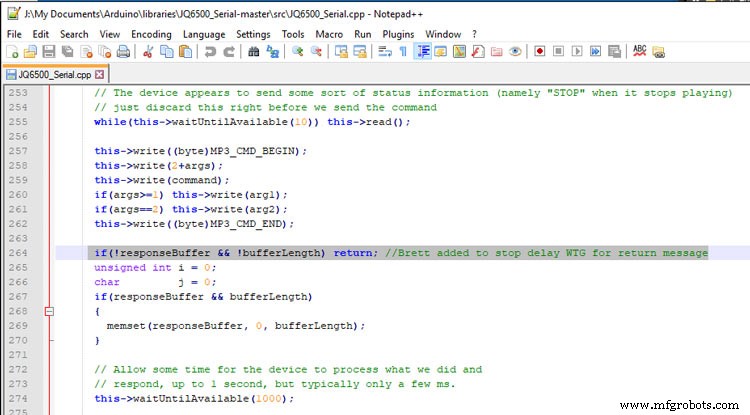
After adding the line after line 263 if(!responseBuffer &&!bufferLength) return; the clock worked fine.
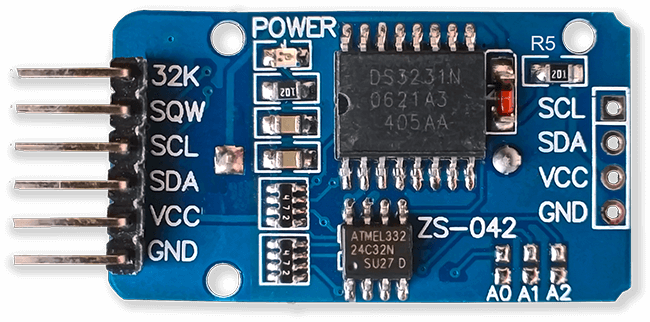
Step 18:Modify the Real Time Clock RTC
Modification of DS3231 AT24C32 I2C Precision Real Time Clock Module
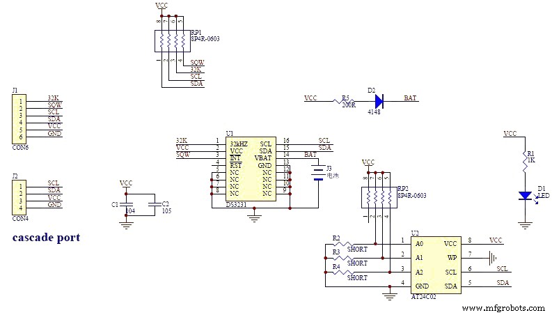
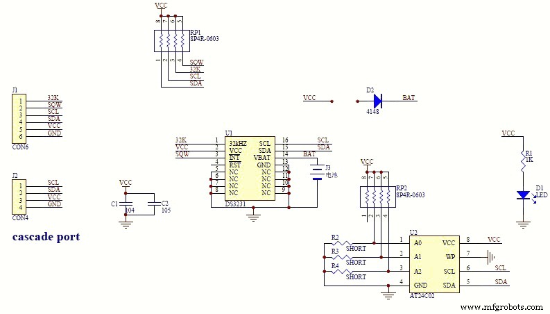
My clock uses a DS3231 AT24C32 I2C Precision Real Time Clock Module.The module comes supplied with a Lithium-Ion rechargeable battery see pic 1. I use a non rechargeable battery so have removed resistor R5 from the module as pic 2.
Step 19:Dial Construction Drawing
The dial requires oround 700 seperate drilling operations and numerous aounts of cutting and filling to complete.
I don't have a CNC machine so it was all done by hand.
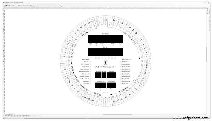
The dial was drawn up on a Cad program (TurboCab) pic 4 and printed out onto injet water slide decal paper.
This shows a close up of dial printing with 3mm LEDs to give an idea of scale. The quality from the water slide decal paper is very good far better than my old ink jet can print.
The enclosed zip file contains the dial picture in various file formats including a 4000x4000 png file.
Contact me for other file types!
TurboCad_Drawings.zip
Step 20:Dial Construction Cutting Out &Drilling
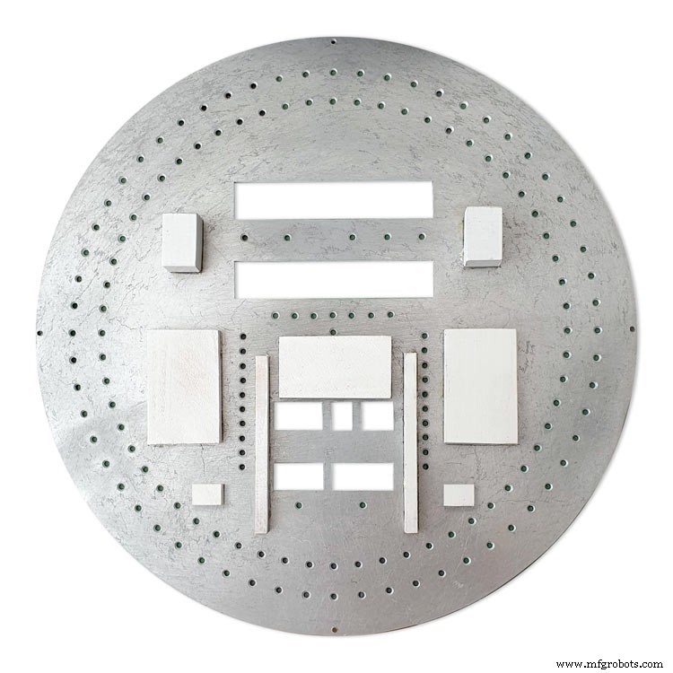
The dial is cut from 1.5mm thick alluminium sheet as it has to carry the weight of all the electronics and wiring.
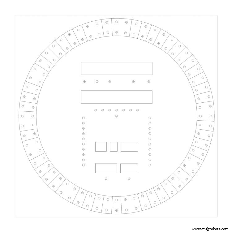
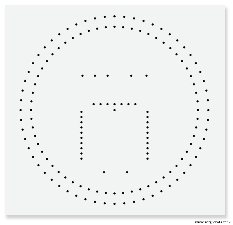
Make a template by printing out the dial from your CAD program onto A3 paper.Make sure it has center marks for the LED holes and also the cutouts for the 7 segment LED displays.
Carefully cutout the 7 segment display openings on the template with a craft knife.Place the template on the alluminium sheet and tape it down to stop it moving. Center punch all the center marks for the LEDs and draw around the openings for the 7 segment displays with a marker pen.
Remove the template to reveal the cutting/drilling marks on the alluminium sheets protective film.
Draw a circle the size of your dial with a compass using the center punch mark from the DCF77 symbel LED as a center point.
Cut out the circle with a hacksaw/jigsaw or bandsaw fitted with a metal cutting blade.

Cut out the 7 segment display openings with a coping/jig or fret saw. Take your time with this as it will save a lot of filing later.

Drill out all the holes for the LEDs. I start with a 1mm bit then a 2mm and then finally a 3mm bit.
This leaves the LEDs a friction fit once the paint and varnish is applied to the dial.
Mark center punch and drill 3 or 4 dial mounting holes.
With the holes drilled the protective film can be removed from the alluminium sheet and the dial rubbed down to remove all rough edges.
This will also give a good key for the paint.
Prime and paint with acrylic paint then a coat of matt varnish. Antique White looks better on old dials or use pure white on modern dials.
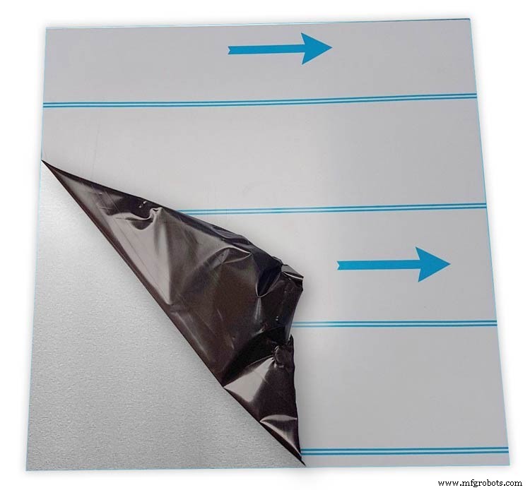
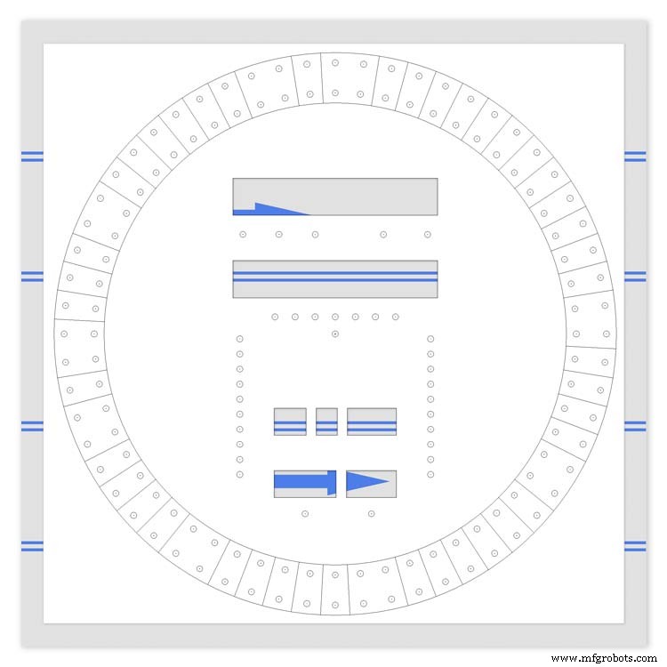
Step 21:Dial Construction Applying the Dial Transfer Decal
Water slide decals are printed out on special paper on an inkjet printer. Once dry they are soaked in water then slid into place.
They give a very detailed print and once given a coat of varnish are tough. Don't forget to order transparent tranfers so the dial colour can be seen through the transfer. Follow the instructions with the pack as they do vary.
On my transfers I print out the dial on transfer paper let it dry and then cut it out to just under the size of the dial. I then give it a coat of acrylic varnish. When the varnish is dry the transfer is soaked in water until the transparent transfer comes away from the white backing sheet.
Line up the transfer with the dial and slide it over the dial.
Make sure the center dots line up with the center of the holes in the dial then slide the backing sheet back off the transfer.
Carry out any final adjustments then remove any airbubbles.
Allow to dry then apply some clear acrylic varnish to protect the transfer. Once this dries carfully cut away the transfer around the 7 segment display cutouts with a craft knife. Then cut the transfer off all the LEDs hole. I used a leather punch just smaller than the hole. Give it another coat of varnish to seal all the cut edges Leave it overnight to dry.

Search for "Transparent Water Slide Decal Paper A3"
Step 22:Dial Construction PCB/Vero Board Mounts
The PCBs and Vero Boards are fixed to wooden mounting blocks cut from off cuts of timber.These block are glued to the dial with impact adhesive. Follow the instructions on the impact adhesive but normaly you apply to both surfaces leave until tacky then press together for an instant bond that hardens fully over night.
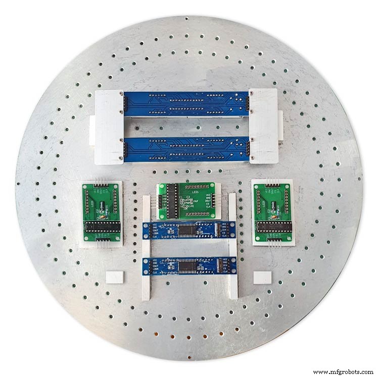
Lower modules in position on the wooden blocks ready to be secured by M2 screws.The main PCB fits on top of the lower 7 segment modules and is raised up on brackets.
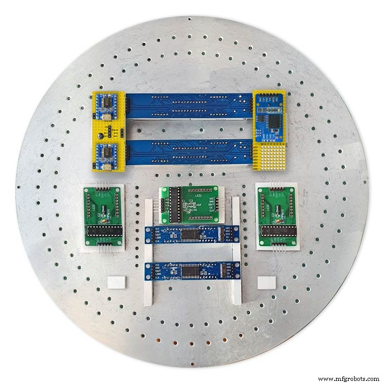
JQ6500 sound module board and LED wiring board in place. RTC is mounted on the LED wiring board but connected on the main board.
Main board mounted on custom made standoff brackets.
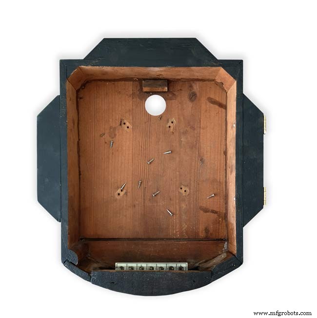
Step 23:Dial Surround &Back Box Restoration
Dial Surround Restoration
I sourced my clock case from eBay. It had no dial or brass bezal and the rear box was broken.
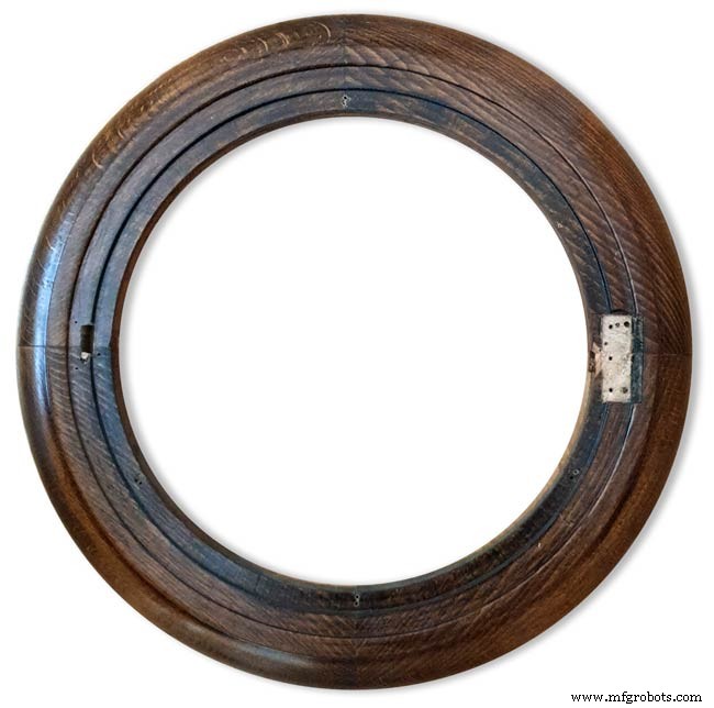
The original Oak dial surround was covered in a thick coat of varnish and years of dirt.
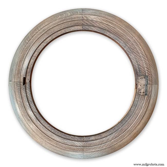
I used paint stripper to remove the varnish and then wood bleach to get rid of the very dark areas of wood.
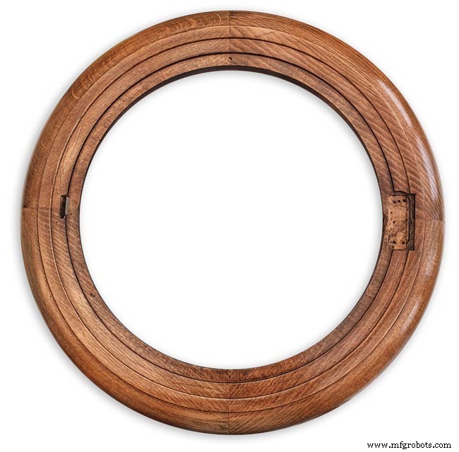
The surround was then varnished with matt acrylic to enhance the grain of the wood.
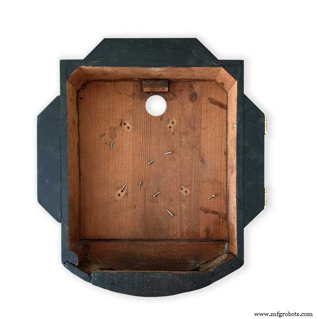
The back box was very badly damaged and had to be screwed and glued back together. I has to fill many hole and cracks in the wood work and decided to paint it matt black.
Step 24:Correcting MAX7219 7 Segment Module Display Errors
The 7 segment modules seem to work fine work fine on their own. However, once you start daisy chaining them together the displays tend to error.
0.39" Display

The datasheet calls for a 10μF and 0.1μ capacitor across the supply rails as close to the MAX7219 as possible.I notice the 0.1μF capacitor is in place but the 10μF capacitor is missing.
Add this capacitor in the 2 holes above the diode D1 on the rear of the display.

There is also a diode in series with the supply rail. When daisy chaining modules all these diodes are in series so the further down the line of modules the more volts are dropped causing display errors.
Remove this diode on each display and replace it with a wire strap.
0.56" Display
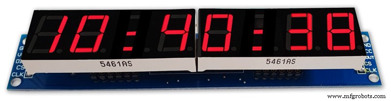
Note the black tape over the 3rd and 6th digit tp make colons.
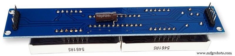
10μF capacitor added to the rear of the PCB on the +&- pins of the MAX7219 IC
The 1N4148 diode is replaced by a wire link.
Step 25:Increasing the Constrast on the 7 Segment Modules
The 7 segment displays traditionally would have a sheet of red perspex to match the LED colour placed over the top of the display. This was designed to hide the not lit segments and provide contrast to the LED segments that are on.
In my clock I have used Neutral Density Heat Proof Dimming Transparent Acetate Sheet ND 0.9.
This hide the not lit LED segments and provides the contrast needed in bright conditions. It has the advantage that it work on all colour LEDs.
My 0.56" modules are a deeper red than the 0.39" modules so I would need 2 different matching red perspex to sheets to work well on both modules.
The acetae shhet is also very cheap the only disadvantage is that it is too flimsy to cover large areas without support.
The picture above shows the effect of the ND sheet. The lit LED segements have more contrast and the unlit LED segments are hidden. It also hides the black tape masking for the colon display.
Step 26:Modification of the RTC Time 7 Segment Display Module to Show Colon Digit Seperators
The standard display only has decimal points to separate the digits and has no colon that would normally be used in a clock display.
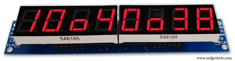
In code I have set digits 3 and 6 to always display a "o" lower case o
Black plastic tape is then cut with a craft knife and placed over the 2 digits leaving a small section showing

When the display is on these visible sections now display colons
Step 27:Dial &Case Fitting
The dial is hidden behind a brass bezal. The brass bezal was missing from my clock but I was able to get one from a horological supplier.
The brass bezal is held down by a brass catch set into the dial surround.

With the brass bezal removed you can see the recess cut in the surround for the brass bezal hidge. My new bezal hinge was a differnet shape to the original hinge so I had to cut it in with a chisle at the front and fill the rear in with a piece of wood stained to match the surround.
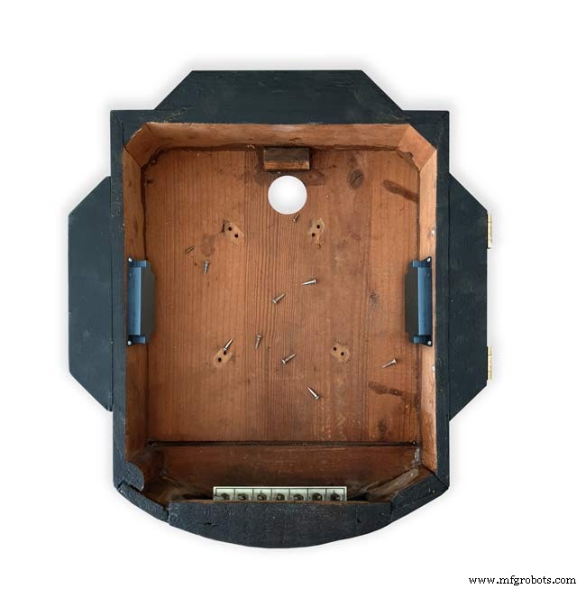
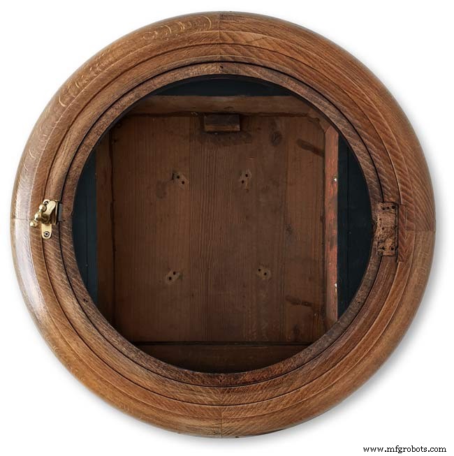
The dial has been removed showing the dial mounting holes on the wood surround and the wooden back box behind it.
Shows the surround removed revealing the back box construction. The switch panel can be seen folded up above the trap door in the base of the back box.

Shows the side view of the case with dial and wood dial surround locked in place. The dial surround is locked by the same type of catch used to lock the brass bezal in place. Note the small brass screw below the brass tag on the dial bezal. this ensurse the brass bezal lines up correctly with the dial when the brass bezal is closed.
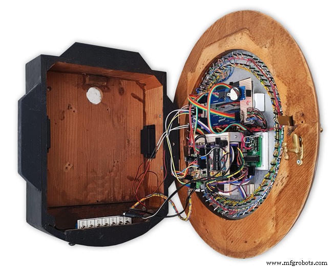
Step 28:Dial &Case Fitting Modern Style Case and Surround
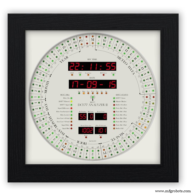
This case uses a large picture frame with a basic square back box to hold the electronics and to hold the dial away from the wall to give it some depth.
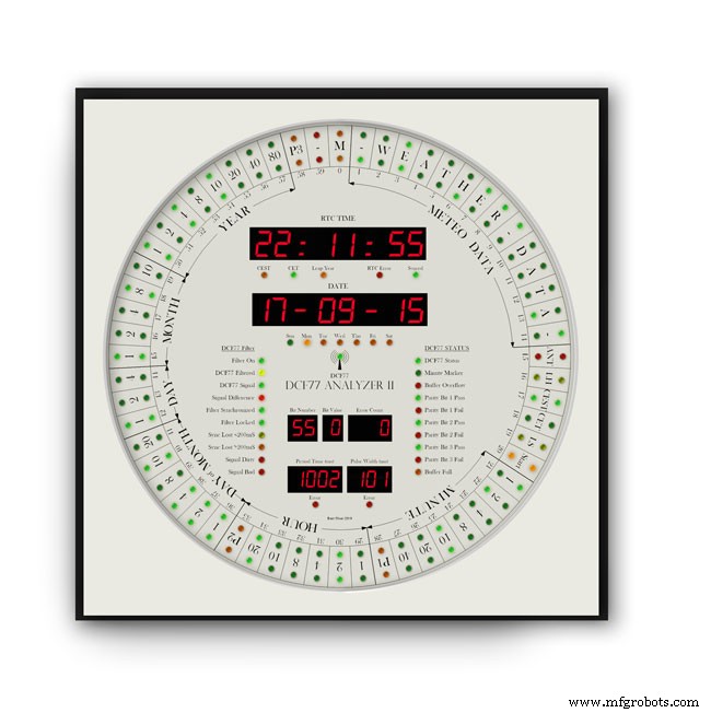
Outer frame and glass removed to reveal the thick photomount card over the dial (a thin ply or wood sheet can also be used with a routed edge)
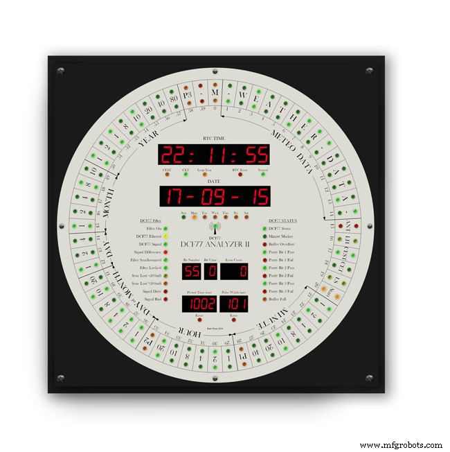
Photo mount removed to show how the dial is fixed to the back plate with 4 small screws.
The backplate holds the dial and has a large circular cutout for the electronics.

It is hinged at one edge to the dial can swing out.
The speakers are mounted on both sides with holes and grills as per the other case.

The switches are mounted on the side in a cutout with the speaker grill above.
Step 29:DCF77 Filter
DCF77 Filter
When switched on the Udo Klein's Super Filter actively processes the incoming DCF77 signal from the antenna/receiver. After a few minutes of sampling the DCF77 signal the Super Filter will predict the DCF77 signal and use this to determine if the incoming signal contains any errors. The Super Filter will then synthesize a corrected DCF77 signal even if the signal is absent.
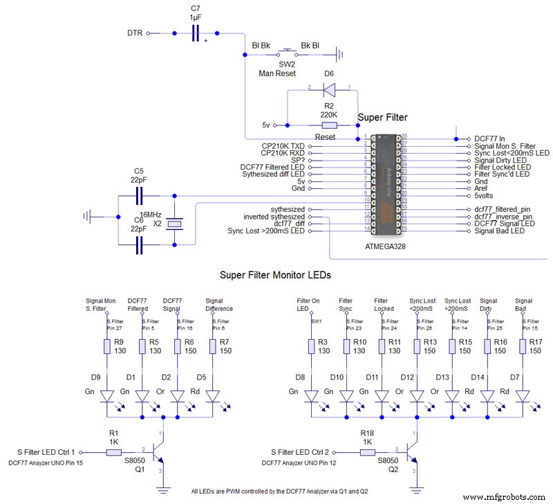
Super Filter Mod See the schematic. I have modified the Super Filter Code to add extra monitor LEDs. In order to do this I have removed 4 modes from the filter just leaving sythesized and inverted sythesized.
Note the PWM LED brightness control is via the Arduino controlling the DCF77 decoding not the Super Filter Arduino. I have also added an LED test to the Super Filter to Match the LED Test on the main clock. This activates on reset or power up. On power up the Supe Filter LED test starts and finishes then the main clock LED terst starts.
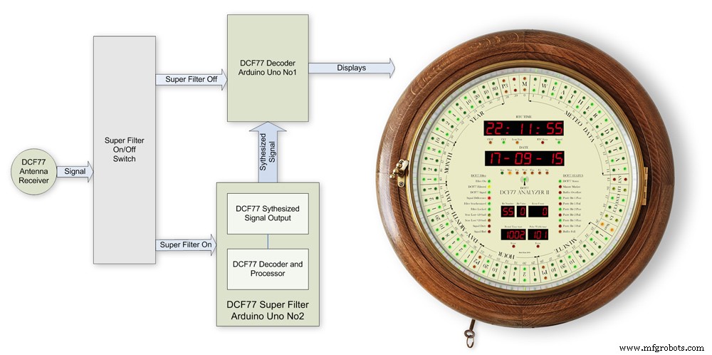
The filter will lock onto the DCF77 signal even if the signal is really noisy. As days progress the filter uses the incomming DCF77 signal to adjust the Arduino crystal frequncy.
This means the filter will stay in time even if the DCF77 signal is lost for many days. In my clock the DCF77 signal is alway fed to the Super Filter Arduino even if the DCF77 Source switch is set to off. This allows the Super Filter to stay in sync and keep adjusting the quartz crystal from the Arduino.
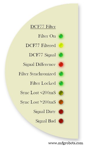
Filter On lights when the DCF77 Source switch is set to FILTER and means the Super Filter is decoding and synthesizing the DCF77 signal
DCF77 Filtered the DCF77 Synthesized signal comming out from the Super Filter
DCF77 Signal the DCF77 signal comming direct from the DCF77 receiver with no filter applied
Signal Difference the differnece between the incomming DCF77 signal and the Synthesized signal. In normal operation this will flash as the received signal shape is often slightly “wider” than the synthesized signal.
Filter Syncronized best possible quality, clock is 100% synced
Filter Locked clock driven by accurate phase, time is accurate but not all decoder stages have sufficient quality for sync
Sync Lost <200mS clock was once synced, inaccuracy below 200 ms, may re-lock if a valid phase is detected
Sync Lost>200mS clock was once synced but now may deviate more than 200 ms, must not re-lock if valid phase is detected Signal Dirtytime data available but unreliable Signal Bad waiting for good enough signal
More details on some of the above
Filter Syncronized - Timing is completely locked to DCF77 and the data is most up to date.
Filter Locked - If the quality factor of the decoder stages drops but the quality factor of the phase decoder stays high enough the clock will transition into the state locked. In this state it is still phase locked to DCF77 but it may become out of sync by a second but only if a leap second is transmitted.
Sync Lost <200mS - This indicates that the quality factor of the decoder stage and the quality factor of the phase decoder have dropped. In this state the timer relies on the quartz crystal timimgs and the clock will slowly drift out of phase with the DCF77 signal. This is a warning that the clock may be running slightly out of sync.
Sync Lost>200mS - Once the clock has started to drift out of phase for more than a set period of time (depending on the tuned accuracy of the quartz crystal) then this LED will light
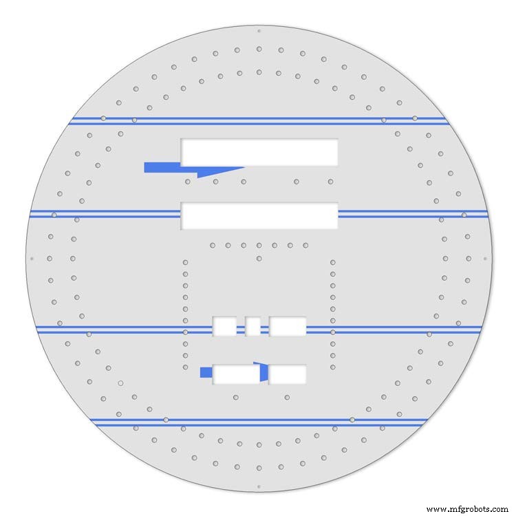
Animation showing filter synchronized
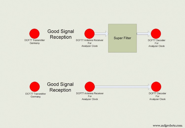
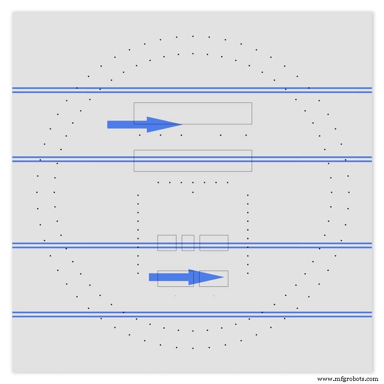
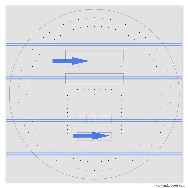
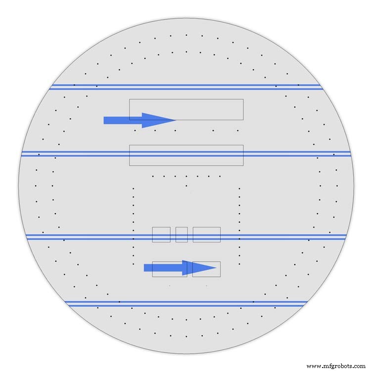
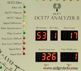
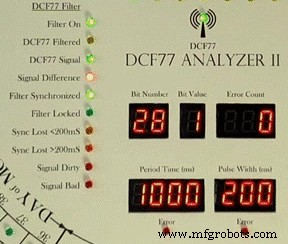
Super Filter example
The top row shows the Super Filter turned on. Once synchronized and tuned into the signal the Super Filter will synthesize a good signal even when the signal is completely lost. On a noisy signal the Super Filter will search for known signal bits and keep itself synchronized to the transmitter. The bottom row shows the Super Filter turned off. Whatever signal is received (good or bad) is sent to the decoder.
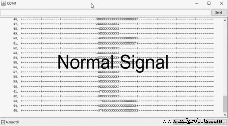
Super Filter correcting a noisy signal as displayed on the DCF77 Scope included with the DCF77 library.
Normal Signal No super filter - Normal signal from the DCF77 reciever Noisy
Signal No Super Filter - The aerial is moved near a LCD screen to generate noiseover the signal
No Signal- The aerial is disconnected and moved connected via the super filter
Noise On Superfilter On- The noise is filtered out leaving a perfect signal.
Super Filter turned Off and a bad signal the clock errors and will reject this minutes data.Note the DCF77 Filtered LED pulses as normal but as the Filter is turned off the filtered signal is not fed to the clock's decoder.
Super Filter turned On and a bad signal the clock has no errors and the clock is able to decode the data as normal.Note the DCF77 Filtered LED pulses as normal and is fed to the clock's decoder
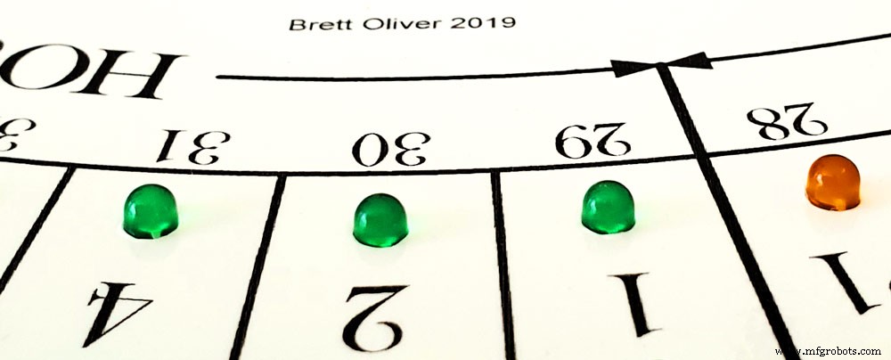
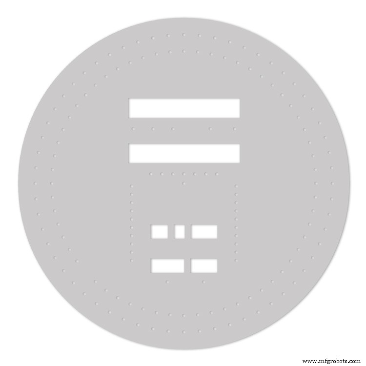
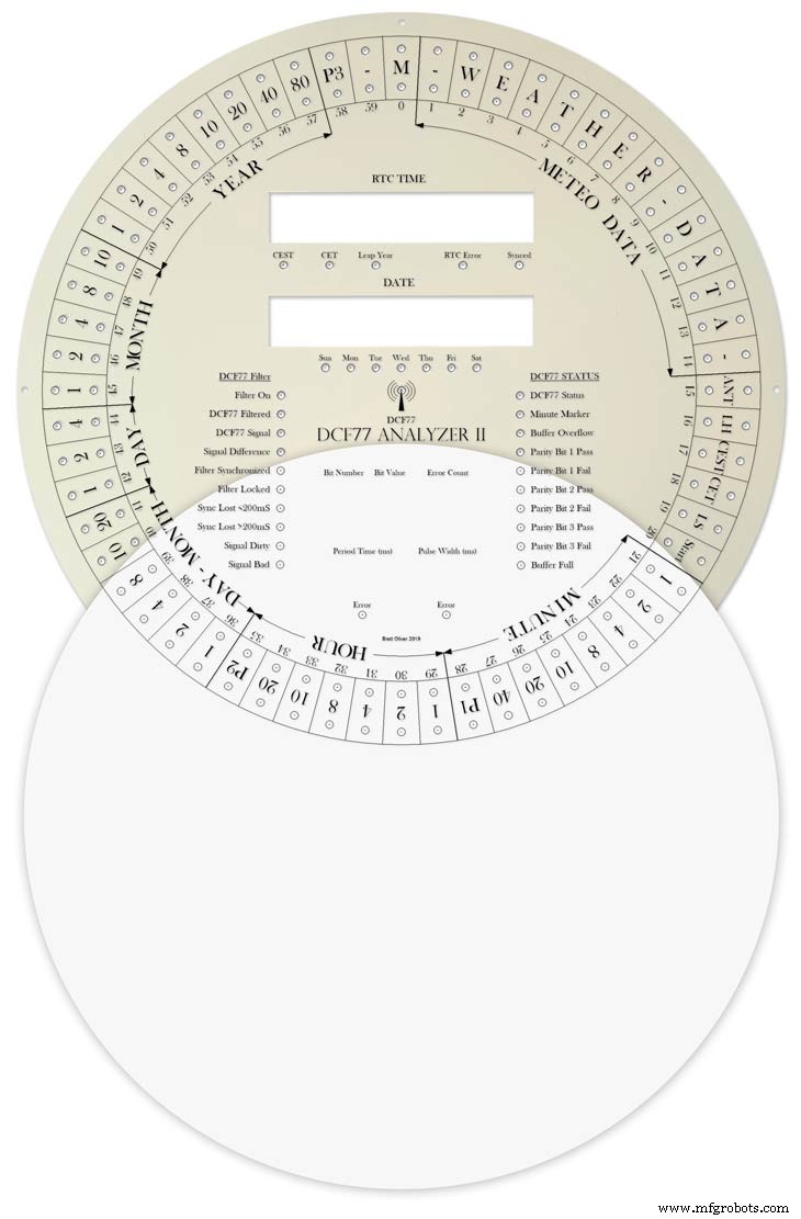
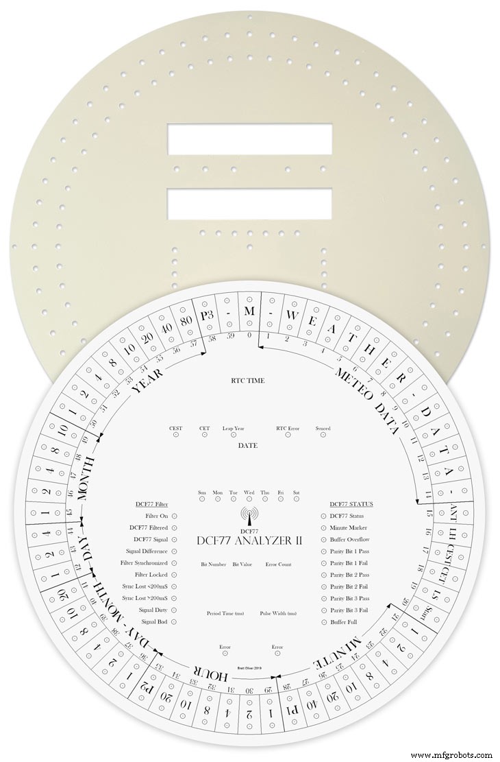
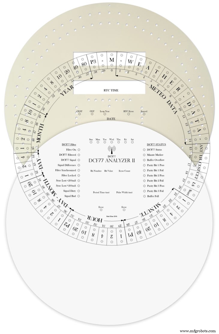
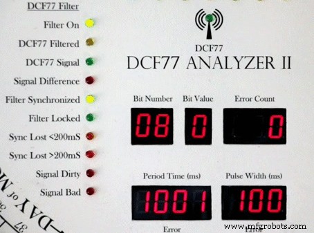
Step 30:DCF77 Time Code
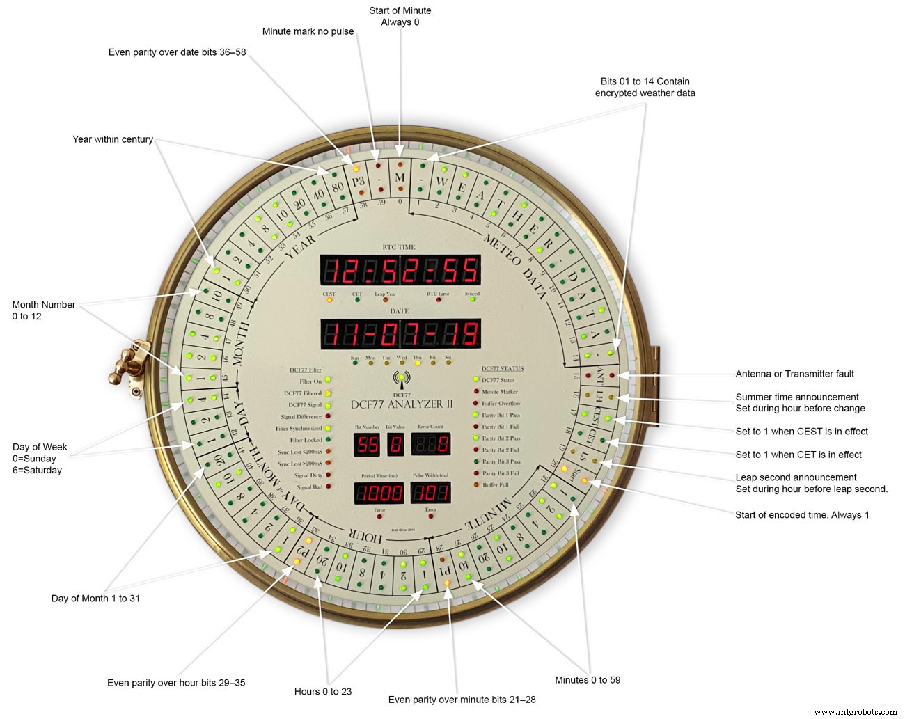
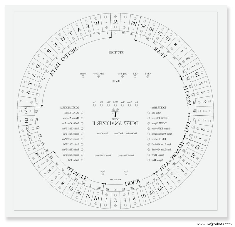
This picture shows the dial code as it is displayed on my dial and allows you to read the incomming DCF77 signal.
Step 31:Code
There are 2 seperates codes to download one for the Superfilter and one for the Analyzer part of the clock.
DCF_77_ANALYZER_CLOCK_Mk2_43.zip Superfilter07DCF77AnalyzerMK2.zip
<섹션 클래스="섹션 컨테이너 섹션 축소 가능" id="코드">
No preview (download only).
No preview (download only).
 This is the schematic to show the MAX7219 dot matrix module wirng to the LEDs
 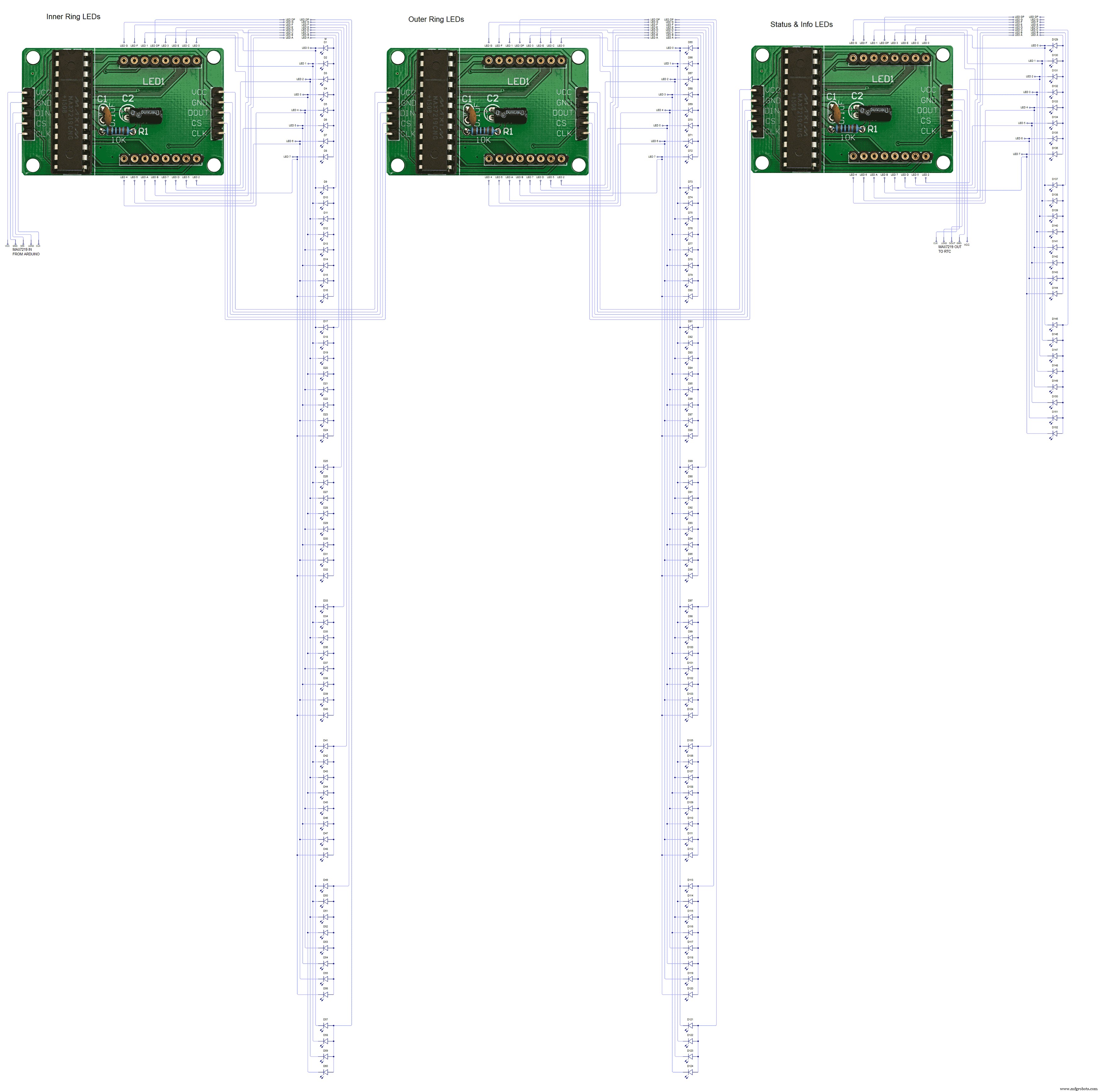 This shows the wiring for the MAX7219 7 segment display modules
제조공정
이 Arduino Tutorial에서는 DS3231 Real Time Clock Module을 사용하는 방법을 배웁니다. 다음 비디오를 보거나 아래에 작성된 튜토리얼을 읽을 수 있습니다. 개요 여기에 오는 첫 번째 질문은 Arduino 자체에 내장된 시간 측정기가 있는 경우 Arduino 프로젝트에 대해 실제로 별도의 RTC가 필요한 이유입니다. 요점은 RTC 모듈이 배터리로 실행되며 마이크로컨트롤러를 다시 프로그래밍하거나 주 전원을 분리하더라도 시간을 추적할 수 있다는 것입니다. DS3231 실시간 시계 DS3231은 시
이 프로젝트에서는 Arduino 터치 스크린 MP3 음악 플레이어와 알람 시계를 만드는 방법을 보여 드리겠습니다. 다음 비디오를 보거나 아래에 작성된 튜토리얼을 읽을 수 있습니다. 개요 홈 화면에는 큰 시계, 날짜 및 온도 정보, 뮤직 플레이어 및 알람 시계용 버튼 2개가 있습니다. 뮤직 플레이어에 들어가면 화면 중앙에 있는 큰 재생 버튼을 눌러 음악 재생을 시작할 수 있습니다. 바로 옆에는 이전 또는 다음 곡을 재생할 수 있는 두 개의 버튼이 더 있습니다. 이 버튼 위에는 노래 진행률 표시줄이 있고 화면 하단에는 볼