

제조공정

산업 제조
<메인 클래스="사이트 메인" id="메인">
이 Arduino 튜토리얼에서는 최대 1.8km의 거리에서 여러 Arduino 보드 간에 장거리 무선 통신을 할 수 있는 HC-12 무선 직렬 통신 모듈을 사용하는 방법을 배웁니다. 자세한 내용은 다음 동영상을 보거나 아래에 작성된 튜토리얼을 참조하세요.
이 튜토리얼에서는 HC-12 모듈을 연결하고 두 Arduino 간의 기본 통신을 만드는 방법을 설명하는 두 가지 기본 예제와 첫 번째 Arduino에서 가속도계 센서를 사용하여 두 번째 Arduino에서 스테퍼의 위치를 무선으로 제어하는 추가 예제를 만들었습니다. 아두이노.
<그림 클래스="aligncenter">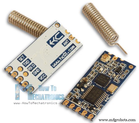
먼저 HC-12 무선 직렬 포트 통신 모듈을 자세히 살펴보겠습니다. 다음은 몇 가지 사양입니다.
이 값은 실제로 표에 표시된 것처럼 선택한 직렬 및 무선 전송 속도에 따라 다릅니다.
<그림 클래스="aligncenter">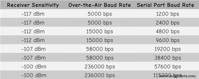
HC-12 모듈에는 실제로 사용자가 프로그래밍할 필요가 없는 마이크로 컨트롤러가 있습니다. 모듈을 구성하기 위해 우리는 단순히 AT 명령을 사용합니다. 이 명령은 Arduino, PC 또는 직렬 포트를 사용하는 다른 마이크로컨트롤러에서 보낼 수 있습니다. AT 명령 모드에 들어가려면 모듈의 "Set" 핀을 낮은 논리 레벨로 설정하기만 하면 됩니다.
이제 HC-12 모듈을 Arduino에 연결하고 첫 번째 예제를 만들어 보겠습니다. 다음은 회로도입니다. 모듈의 작동 전압은 3.2V ~ 5.5V이며 보다 안정적인 작업을 위해 디커플링 커패시터와 외부 전원 공급 장치를 사용하는 것이 좋습니다. 그러나 이 튜토리얼의 세 가지 예 모두에서 PC USB를 전원으로 사용했으며 아무런 문제가 없었습니다.
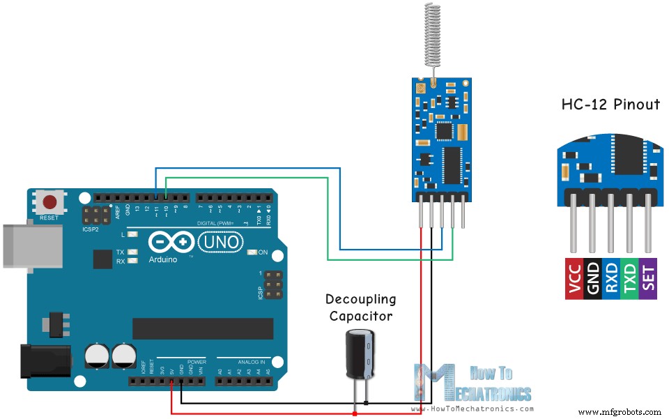
첫 번째 모듈은 Arduino UNO에 연결하고 두 번째 모듈은 Arduino MEGA에 연결했지만 물론 원하는 보드를 사용할 수 있습니다.
아래 링크에서 이 Arduino 튜토리얼에 필요한 구성요소를 얻을 수 있습니다.
다음은 직렬 모니터를 사용하여 두 모듈 간의 기본 통신인 첫 번째 예제의 Arduino 코드입니다.
/*    Arduino Long Range Wireless Communication using HC-12
                      Example 01
   by Dejan Nedelkovski, www.HowToMechatronics.com
*/

#include <SoftwareSerial.h>

SoftwareSerial HC12(10, 11); // HC-12 TX Pin, HC-12 RX Pin

void setup() {
  Serial.begin(9600);             // Serial port to computer
  HC12.begin(9600);               // Serial port to HC12

}

void loop() {
  while (HC12.available()) {        // If HC-12 has data
    Serial.write(HC12.read());      // Send the data to Serial monitor
  }
  while (Serial.available()) {      // If Serial monitor has data
    HC12.write(Serial.read());      // Send that data to HC-12
  }
}Code language: Arduino (arduino)
두 Arduinos에 동일한 코드가 사용됩니다. 두 개의 별도 컴퓨터에 두 개의 Arduino를 연결할 수 있지만 한 대의 컴퓨터를 사용할 수도 있습니다.
<그림 클래스="aligncenter">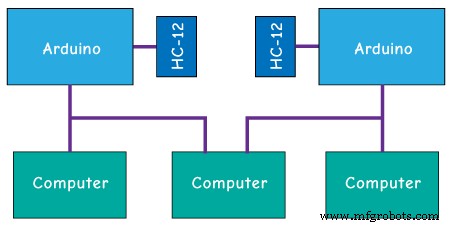
이 경우 첫 번째 Arduino를 컴퓨터에 연결하면 모델과 COM 포트를 선택하고 Arduino에 코드를 업로드해야 합니다. 그런 다음 두 번째 Arduino를 연결하고 두 번째 Arduino가 연결된 다른 COM 포트를 선택한 다음 동일한 코드를 업로드하려면 Arduino IDE를 다시 시작해야 합니다.
따라서 두 개의 Arduino IDE가 실행되면 직렬 모니터를 시작하고 통신이 제대로 작동하는지 테스트할 수 있습니다. 직렬 모니터에 입력하는 모든 내용은 하나에서 다른 Arduino로 전송됩니다.
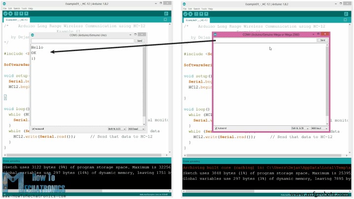
코드 작동 방식: 따라서 직렬 모니터에 무언가를 입력하고 보내기 버튼을 클릭하면 첫 번째 Arduino에서 Serial.available() 함수가 있는 while 루프가 true가 되고 HC12.write() 함수를 사용하여 데이터를 보냅니다. 직렬 모니터를 HC-12 모듈에 연결합니다. 이 모듈은 데이터를 무선으로 두 번째 HC-12 모듈로 전송하므로 두 번째 Arduino에서 HC12.available() 함수가 있는 while 루프가 true가 되고 Serial.write() 함수를 사용하여 데이터가 직렬 모니터.
AT 명령을 보내고 모듈 매개변수를 구성하는 데 동일한 코드를 사용할 수 있습니다. 모듈의 "Set" 핀을 접지 또는 Arduino의 디지털 핀에 연결하고 핀을 낮은 로직 레벨로 설정하기만 하면 됩니다.
<그림 클래스="aligncenter">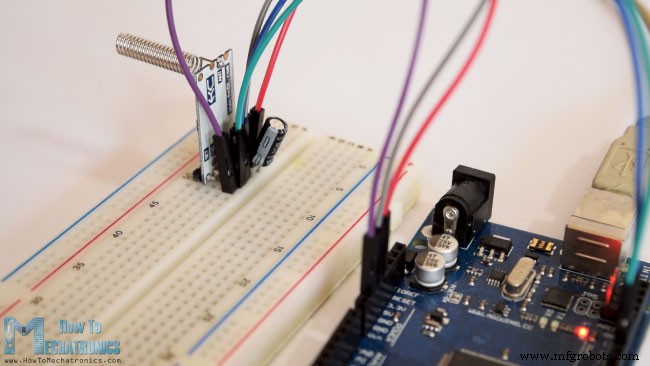
모드에 성공적으로 진입했는지 테스트하기 위해 직렬 모니터에서 "AT"를 입력하면 "OK"라는 응답 메시지가 표시됩니다. AT Command는 총 12개가 있으며 Baud Rate, Channel, 송신 전력 등 다양한 파라미터를 변경하는 데 사용됩니다. 예를 들어 "AT+B38400"을 입력하면 모듈의 baud rate는 다음과 같이 설정됩니다. 38400.
1. AT – 테스트 명령.
예:모듈에 "AT"를 보내고 모듈은 "OK"를 반환합니다.
2. AT+Bxxxx – 직렬 포트 전송 속도를 변경합니다.
사용 가능한 전송 속도:1200bps, 2400bps, 4800bps, 9600bps, 19200bps, 38400bps, 57600bps 및 115200bps. 기본값:9600bps.
예:모듈에 "AT+B38400"을 보내면 모듈이 "OK+B19200"을 반환합니다.
3. AT+Cxxxx – 무선 통신 채널을 001에서 100으로 변경합니다.
기본값:채널 001, 작동 주파수 433.4MHz. 각 다음 채널은 400KHz 더 높습니다.
예: 모듈을 채널 006으로 설정하려면 'AT+C006' 명령을 모듈에 보내야 하며 모듈은 'OK+C006'을 반환합니다. 새 작동 주파수는 435.4MHz입니다.
이제 두 번째 예를 이동하겠습니다. 여기에서 서로 다른 통신 채널을 선택하기 위해 두 개의 푸시 버튼을 사용하고 수신 데이터를 저장하는 다른 방법을 볼 것입니다.
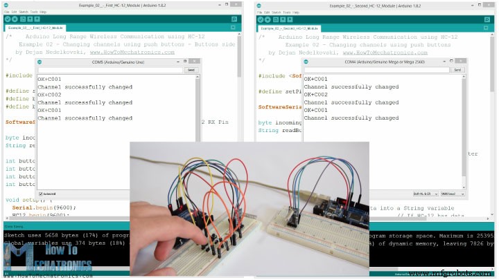
참고:두 HC-12 모듈의 "설정" 핀은 두 개의 Arduinos의 핀 번호 6에 연결되고 첫 번째 Arduino의 두 개의 버튼은 핀 4와 3에 연결됩니다.
첫 번째 Arduino 코드:
/*    Arduino Long Range Wireless Communication using HC-12
    Example 02 - Changing channels using push buttons - Buttons side
   by Dejan Nedelkovski, www.HowToMechatronics.com
*/

#include <SoftwareSerial.h>

#define setPin 6
#define button1 4
#define button2 3

SoftwareSerial HC12(10, 11);         // HC-12 TX Pin, HC-12 RX Pin

byte incomingByte;
String readBuffer = "";

int button1State = 0;
int button1Pressed = 0;
int button2State = 0;
int button2Pressed = 0;

void setup() {
  Serial.begin(9600);                   // Open serial port to computer
  HC12.begin(9600);                     // Open serial port to HC12
  pinMode(setPin, OUTPUT);
  pinMode(button1, INPUT);
  pinMode(button2, INPUT);
  digitalWrite(setPin, HIGH);           // HC-12 normal, transparent mode
}

void loop() {
  // ==== Storing the incoming data into a String variable
  while (HC12.available()) {             // If HC-12 has data
    incomingByte = HC12.read();          // Store each icoming byte from HC-12
    readBuffer += char(incomingByte);    // Add each byte to ReadBuffer string variable
  }
  delay(100);
  // ==== Sending data from one HC-12 to another via the Serial Monitor
  while (Serial.available()) {
    HC12.write(Serial.read());
  }

  // ==== If button 1 is pressed, set the channel 01
  button1State = digitalRead(button1);
  if (button1State == HIGH & button1Pressed == LOW) {
    button1Pressed = HIGH;
    delay(20);
  }
  if (button1Pressed == HIGH) {
    HC12.print("AT+C001");               // Send the AT Command to the other module
    delay(100);
    //Set AT Command Mode
    digitalWrite(setPin, LOW);           // Set HC-12 into AT Command mode
    delay(100);                          // Wait for the HC-12 to enter AT Command mode
    HC12.print("AT+C001");               // Send AT Command to HC-12
    delay(200);
    while (HC12.available()) {           // If HC-12 has data (the AT Command response)
      Serial.write(HC12.read());         // Send the data to Serial monitor
    }
    Serial.println("Channel successfully changed");
    digitalWrite(setPin, HIGH);          // Exit AT Command mode
    button1Pressed = LOW;
  }

  // ====  If button 2 is pressed, set the channel 02
  button2State = digitalRead(button2);
  if (button2State == HIGH & button2Pressed == LOW) {
    button2Pressed = HIGH;
    delay(100);
  }
  if (button2Pressed == HIGH) {
    HC12.print("AT+C002"); // Send the AT Command to the other module
    delay(100);
    //Set AT Command Mode
    digitalWrite(setPin, LOW);           // Set HC-12 into AT Command mode
    delay(100);                          // Wait for the HC-12 to enter AT Command mode
    HC12.print("AT+C002");               // Send AT Command to HC-12
    delay(200);
    while (HC12.available()) {           // If HC-12 has data (the AT Command response)
      Serial.write(HC12.read());         // Send the data to Serial monitor
    }
    Serial.println("Channel successfully changed");
    digitalWrite(setPin, HIGH);
    button2Pressed = LOW;
  }
  checkATCommand();
  readBuffer = "";                       // Clear readBuffer
}
// ==== Custom function - Check whether we have received an AT Command via the Serial Monitor
void checkATCommand () {
  if (readBuffer.startsWith("AT")) {     // Check whether the String starts with "AT"
    digitalWrite(setPin, LOW);           // Set HC-12 into AT Command mode
    delay(200);                          // Wait for the HC-12 to enter AT Command mode
    HC12.print(readBuffer);              // Send AT Command to HC-12
    delay(200);
    while (HC12.available()) {           // If HC-12 has data (the AT Command response)
      Serial.write(HC12.read());         // Send the data to Serial monitor
    }
    digitalWrite(setPin, HIGH);          // Exit AT Command mode
  }
}Code language: Arduino (arduino)
두 번째 Arduino 코드:
/*    Arduino Long Range Wireless Communication using HC-12
        Example 02 - Changing channels using push buttons
   by Dejan Nedelkovski, www.HowToMechatronics.com
*/

#include <SoftwareSerial.h>

#define setPin 6

SoftwareSerial HC12(10, 11); // HC-12 TX Pin, HC-12 RX Pin

byte incomingByte;
String readBuffer = "";

void setup() {
  Serial.begin(9600);             // Open serial port to computer
  HC12.begin(9600);               // Open serial port to HC12
  pinMode(setPin, OUTPUT);
  digitalWrite(setPin, HIGH);     // HC-12 normal mode
}

void loop() {
  // ==== Storing the incoming data into a String variable
  while (HC12.available()) {             // If HC-12 has data
    incomingByte = HC12.read();          // Store each icoming byte from HC-12
    readBuffer += char(incomingByte);    // Add each byte to ReadBuffer string variable
  }
  delay(100);
  // ==== Sending data from one HC-12 to another via the Serial Monitor
  while (Serial.available()) {
    HC12.write(Serial.read());
  }
  // === If button 1 is pressed, set channel 01
  if (readBuffer == "AT+C001") {
    digitalWrite(setPin, LOW);           // Set HC-12 into AT Command mode
    delay(100);                          // Wait for the HC-12 to enter AT Command mode
    HC12.print(readBuffer);              // Send AT Command to HC-12 ("AT+C001")
    delay(200);
    while (HC12.available()) {           // If HC-12 has data (the AT Command response)
      Serial.write(HC12.read());         // Send the data to Serial monitor
    }
    Serial.println("Channel successfully changed");
    digitalWrite(setPin, HIGH);          // Exit AT Command mode
    readBuffer = "";
  }
  // === If button 2 is pressed, set channel 02
  if (readBuffer == "AT+C002") {
    digitalWrite(setPin, LOW);           // Set HC-12 into AT Command mode
    delay(100);                          // Wait for the HC-12 to enter AT Command mode
    HC12.print(readBuffer);              // Send AT Command to HC-12
    delay(200);
    while (HC12.available()) {           // If HC-12 has data (the AT Command response)
      Serial.write(HC12.read());         // Send the data to Serial monitor
    }
    Serial.println("Channel successfully changed");
    digitalWrite(setPin, HIGH);          // Exit AT Command mode

    readBuffer = "";
  }
  checkATCommand();
  readBuffer = "";                       // Clear readBuffer
}
// ==== Custom function - Check whether we have received an AT Command via the Serial Monitor
void checkATCommand () {
  if (readBuffer.startsWith("AT")) {     // Check whether the String starts with "AT"
    digitalWrite(setPin, LOW);           // Set HC-12 into AT Command mode
    delay(100);                          // Wait for the HC-12 to enter AT Command mode
    HC12.print(readBuffer);              // Send AT Command to HC-12
    delay(200);
    while (HC12.available()) {           // If HC-12 has data (the AT Command response)
      Serial.write(HC12.read());         // Send the data to Serial monitor
    }
    digitalWrite(setPin, HIGH);          // Exit AT Command mode
  }
}Code language: Arduino (arduino)
코드 설명:
따라서 모듈이 일반 투명 모드에서 작동하려면 먼저 핀을 정의하고 "Set" 핀을 높은 로직 레벨로 설정해야 합니다. 첫 번째 while 루프를 사용하면 들어오는 데이터를 String 변수에 저장하므로 더 잘 처리할 수 있습니다.
// ==== Storing the incoming data into a String variable
while (HC12.available()) { // If HC-12 has data
incomingByte = HC12.read(); // Store each icoming byte from HC-12
readBuffer += char(incomingByte); // Add each byte to ReadBuffer string variable
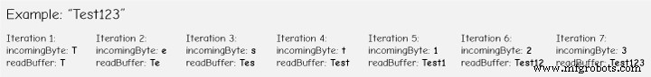
}Code language: Arduino (arduino)들어오는 데이터는 항상 한 번에 한 바이트씩 오기 때문에 예를 들어 두 번째 Arduino에서 "Test123" 문자열을 보내면 이 while 루프는 7번의 반복을 수행합니다. 각 반복은 HC12.read() 함수를 사용하여 들어오는 각 바이트 또는 문자를 읽고 "readBuffer"라는 문자열 변수에 추가합니다.
다음으로 첫 번째 푸시 버튼을 사용하여 통신 채널을 변경하는 방법을 살펴보겠습니다. 따라서 첫 번째 푸시 버튼을 누르면 HC12.print() 함수를 사용하여 "AT+C001" 문자열을 HC-12 모듈이나 두 번째 Arduino로 보냅니다.
if (button1Pressed == HIGH) {
    HC12.print("AT+C001");               // Send the AT Command to the other module
    delay(100);
    //Set AT Command Mode
    digitalWrite(setPin, LOW);           // Set HC-12 into AT Command mode
    delay(100);                          // Wait for the HC-12 to enter AT Command mode
    HC12.print("AT+C001");               // Send AT Command to HC-12
    delay(200);
    while (HC12.available()) {           // If HC-12 has data (the AT Command response)
      Serial.write(HC12.read());         // Send the data to Serial monitor
    }
    Serial.println("Channel successfully changed");
    digitalWrite(setPin, HIGH);          // Exit AT Command mode
    button1Pressed = LOW;
  }Code language: Arduino (arduino)
이 문자열이 두 번째 Arduino에서 수신되면 HC-12 모듈을 AT 명령 모드로 설정한 다음 동일한 문자열 "AT+C001"을 작성하여 모듈을 통신 채널 번호 1로 설정합니다.
// At the second Arduino

// === If button 1 is pressed, set channel 01
  if (readBuffer == "AT+C001") {
    digitalWrite(setPin, LOW);           // Set HC-12 into AT Command mode
    delay(100);                          // Wait for the HC-12 to enter AT Command mode
    HC12.print(readBuffer);              // Send AT Command to HC-12 ("AT+C001")
    delay(200);
    while (HC12.available()) {           // If HC-12 has data (the AT Command response)
      Serial.write(HC12.read());         // Send the data to Serial monitor
    }
    Serial.println("Channel successfully changed");
    digitalWrite(setPin, HIGH);          // Exit AT Command mode
    readBuffer = "";
  }Code language: Arduino (arduino)
다음 while 루프를 사용하여 채널이 성공적으로 변경되었는지 여부에 따라 HC-12 모듈에서 응답 메시지를 인쇄합니다.
while (HC12.available()) {           // If HC-12 has data (the AT Command response)
      Serial.write(HC12.read());         // Send the data to Serial monitor
    }Code language: Arduino (arduino)
첫 번째 Arduino로 돌아가서 첫 번째 HC-12 모듈에 AT 명령을 보내는 것과 동일한 절차를 수행합니다. 같은 방법으로 두 번째 버튼을 눌러 통신 채널 번호를 2로 설정합니다. 따라서 이 방법을 사용하면 통신할 HC-12 모듈을 언제든지 선택할 수 있습니다.
마지막으로 checkATCommand() 사용자 정의 함수는 문자열이 "AT"로 시작하는지 여부를 확인하여 수신된 메시지가 AT 명령인지 확인합니다. 그렇다면 모듈은 AT 명령 모드로 진입하여 명령을 실행합니다.
// ==== Custom function - Check whether we have received an AT Command via the Serial Monitor
void checkATCommand () {
  if (readBuffer.startsWith("AT")) {     // Check whether the String starts with "AT"
    digitalWrite(setPin, LOW);           // Set HC-12 into AT Command mode
    delay(200);                          // Wait for the HC-12 to enter AT Command mode
    HC12.print(readBuffer);              // Send AT Command to HC-12
    delay(200);
    while (HC12.available()) {           // If HC-12 has data (the AT Command response)
      Serial.write(HC12.read());         // Send the data to Serial monitor
    }
    digitalWrite(setPin, HIGH);          // Exit AT Command mode
  }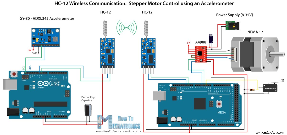
}Code language: Arduino (arduino)이제 세 번째 예를 살펴보겠습니다. 여기에서 첫 번째 Arduino의 가속도계 모듈을 사용하여 두 번째 Arduino에서 스테퍼 모터의 위치를 제어합니다.
<그림 클래스="aligncenter">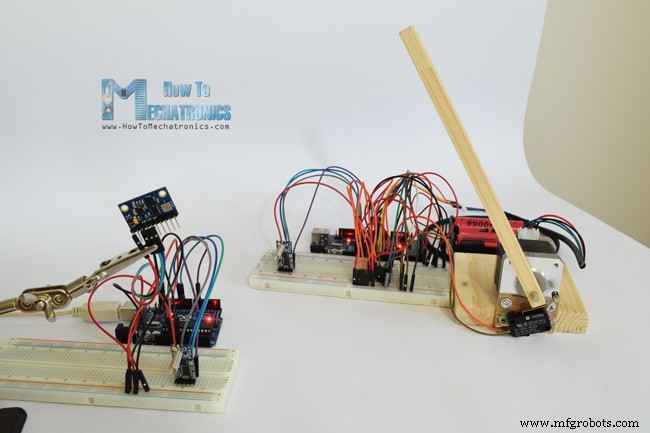
이 회로에는 0도에서 스테퍼 모터의 초기 위치를 찾기 위한 마이크로스위치도 포함되어 있습니다.
아래 링크에서 이 예시에 필요한 구성요소를 얻을 수 있습니다.
가속도계와 스테퍼 모터를 연결하고 사용하는 방법에 대한 자세한 자습서가 이미 있으므로 이 예에서는 코드의 HC-12 부분만 설명합니다.
첫 번째 Arduino – 송신기 코드:
/*   Arduino Long Range Wireless Communication using HC-12
     Example 03 - Stepper Motor Control using Accelerometer - Transmitter, Accelerometer
    by Dejan Nedelkovski, www.HowToMechatronics.com
*/

#include <SoftwareSerial.h>
#include <Wire.h>

SoftwareSerial HC12(10, 11); // HC-12 TX Pin, HC-12 RX Pin

float angle;
int lastAngle = 0;
int count = 0;
int angleSum = 0;

//--- Accelerometer Register Addresses
#define Power_Register 0x2D
#define X_Axis_Register_DATAX0 0x32 // Hexadecima address for the DATAX0 internal register.
#define X_Axis_Register_DATAX1 0x33 // Hexadecima address for the DATAX1 internal register.
#define Y_Axis_Register_DATAY0 0x34
#define Y_Axis_Register_DATAY1 0x35
#define Z_Axis_Register_DATAZ0 0x36
#define Z_Axis_Register_DATAZ1 0x37
int ADXAddress = 0x53;  //Device address in which is also included the 8th bit for selecting the mode, read in this case.
int X0, X1, X_out;
int Y0, Y1, Y_out;
int Z1, Z0, Z_out;
float Xa, Ya, Za;

void setup() {
  HC12.begin(9600);               // Open serial port to HC12
  Wire.begin(); // Initiate the Wire library
  Serial.begin(9600);
  delay(100);

  Wire.beginTransmission(ADXAddress);
  Wire.write(Power_Register); // Power_CTL Register
  // Enable measurement
  Wire.write(8); // Bit D3 High for measuring enable (0000 1000)
  Wire.endTransmission();
}
void loop() {
  // X-axis
  Wire.beginTransmission(ADXAddress); // Begin transmission to the Sensor
  //Ask the particular registers for data
  Wire.write(X_Axis_Register_DATAX0);
  Wire.write(X_Axis_Register_DATAX1);
  Wire.endTransmission(); // Ends the transmission and transmits the data from the two registers
  Wire.requestFrom(ADXAddress, 2); // Request the transmitted two bytes from the two registers
  if (Wire.available() <= 2) { //
    X0 = Wire.read(); // Reads the data from the register
    X1 = Wire.read();
    /* Converting the raw data of the X-Axis into X-Axis Acceleration
      - The output data is Two's complement
      - X0 as the least significant byte
      - X1 as the most significant byte */
    X1 = X1 << 8;
    X_out = X0 + X1;
    Xa = X_out / 256.0; // Xa = output value from -1 to +1, Gravity acceleration acting on the X-Axis
  }
  //Serial.print("Xa= ");
  //Serial.println(X_out);

  // Y-Axis
  Wire.beginTransmission(ADXAddress);
  Wire.write(Y_Axis_Register_DATAY0);
  Wire.write(Y_Axis_Register_DATAY1);
  Wire.endTransmission();
  Wire.requestFrom(ADXAddress, 2);
  if (Wire.available() <= 2) {
    Y0 = Wire.read();
    Y1 = Wire.read();
    Y1 = Y1 << 8;
    Y_out = Y0 + Y1;
    Ya = Y_out / 256.0;
  }

  // Combine X and Y values for getting the angle value from 0 to 180 degrees
  if (Y_out > 0) {
    angle = map(Y_out, 0, 256, 90, 0);
  }
  else if (Y_out < 0) {
    angle = map(Y_out, 256, 0, 90, 0);
    angle = 90 - angle;
  }
  if (X_out < 0 & Y_out < 0) {
    angle = 180;
  }
  if (X_out < 0 & Y_out >0) {
    angle = 0;
  }

  // float to int
  int angleInt = int(angle);
  // Makes 100 accelerometer readings and sends the average for smoother result
  angleSum = angleSum + angleInt;
  count++;
  if (count >= 100) {
    angleInt = angleSum / 100;
    angleSum = 0;
    count = 0;
    // Some more smoothing of acceleromter reading - sends the new angle only if it differes from the previous one by +-2
    if (angleInt > lastAngle + 2 || angleInt < lastAngle - 2) {
      Serial.println(angleInt);
      String angleString = String(angleInt);
      //sends the angle value with start marker "s" and end marker "e"
      HC12.print("s" + angleString + "e");
      delay(10);
      lastAngle = angleInt;
      angleSum = 0;
      count = 0;
    }
  }
}
Code language: Arduino (arduino)
두 번째 Arduino – 수신기 코드:
/*   Arduino Long Range Wireless Communication using HC-12
     Example 03 - Stepper Motor Control using Accelerometer - Receiver, Stepper Motor

    by Dejan Nedelkovski, www.HowToMechatronics.com
*/
#include <SoftwareSerial.h>

SoftwareSerial HC12(10, 11); // HC-12 TX Pin, HC-12 RX Pin

char incomingByte;
String readBuffer = "";

// defines pins numbers
const int dirPin = 4;
const int stepPin = 3;
const int button = 2;

int currentAngle = 0;
int lastAngle = 0;
int rotate = 0;

void setup() {
  Serial.begin(9600);             // Open serial port to computer
  HC12.begin(9600);               // Open serial port to HC12

  // Sets the two pins as Outputs
  pinMode(dirPin, OUTPUT);
  pinMode(stepPin, OUTPUT);
  // Microswitch input, with internal pull-up resistor activated
  pinMode(button, INPUT_PULLUP);
  delay(10);
  digitalWrite(dirPin, HIGH);
  boolean startingPosition = true;
  while (startingPosition) {
    digitalWrite(stepPin, HIGH);
    delayMicroseconds(200);
    digitalWrite(stepPin, LOW);
    delayMicroseconds(200);
    if (digitalRead(button) == LOW) {
      startingPosition = false;
    }
  }
  delay(100);
}
void loop() {
  readBuffer = "";
  boolean start = false;
  // Reads the incoming angle
  while (HC12.available()) {             // If HC-12 has data
    incomingByte = HC12.read();          // Store each icoming byte from HC-12
    delay(5);
    // Reads the data between the start "s" and end marker "e"
    if (start == true) {
      if (incomingByte != 'e') {
        readBuffer += char(incomingByte);    // Add each byte to ReadBuffer string variable
      }
      else {
        start = false;
      }
    }
    // Checks whether the received message statrs with the start marker "s"
    else if ( incomingByte == 's') {
      start = true; // If true start reading the message
    }
  }
  // Converts the string into integer
  currentAngle = readBuffer.toInt();
  // Makes sure it uses angles between 0 and 180
  if (currentAngle > 0 && currentAngle < 180) {
    // Convert angle value to steps (depending on the selected step resolution)
    // A cycle = 200 steps, 180deg = 100 steps ; Resolution: Sixteenth step x16
    currentAngle = map(currentAngle, 0, 180, 0, 1600);
    //Serial.println(currentAngle); // Prints the angle on the serial monitor
    digitalWrite(dirPin, LOW); // Enables the motor to move in a particular direction
    // Rotates the motor the amount of steps that differs from the previous positon
    if (currentAngle != lastAngle) {
      if (currentAngle > lastAngle) {
        rotate = currentAngle - lastAngle;
        for (int x = 0; x < rotate; x++) {
          digitalWrite(stepPin, HIGH);
          delayMicroseconds(400);
          digitalWrite(stepPin, LOW);
          delayMicroseconds(400);
        }
      }
      // rotate the other way
      if (currentAngle < lastAngle) {
        rotate = lastAngle - currentAngle;
        digitalWrite(dirPin, HIGH);        //Changes the rotations direction
        for (int x = 0; x < rotate; x++) {
          digitalWrite(stepPin, HIGH);
          delayMicroseconds(400);
          digitalWrite(stepPin, LOW);
          delayMicroseconds(400);
        }
      }
    }
    lastAngle = currentAngle;  // Remembers the current/ last positon
  }
}Code language: Arduino (arduino)
코드 설명:
따라서 먼저 설정 섹션에서 핀을 정의하고 모듈을 초기화합니다. 그런 다음 가속도계의 X 및 Y 축 값을 읽고 0도에서 180도 사이의 값에 매핑합니다. 가속도계에서 나오는 값은 때때로 불안정하거나 흔들릴 수 있으므로 결과를 매끄럽게 하기 위해 100회 판독값의 평균값을 사용했습니다.
// Makes 100 accelerometer readings and sends the average for smoother result
  angleSum = angleSum + angleInt;
  count++;
  if (count >= 100) {
    angleInt = angleSum / 100;
    angleSum = 0;
    count = 0;
    // Some more smoothing of acceleromter reading - sends the new angle only if it differes from the previous one by +-2
    if (angleInt > lastAngle + 2 || angleInt < lastAngle - 2) {
      Serial.println(angleInt);
      String angleString = String(angleInt);
      //sends the angle value with start marker "s" and end marker "e"
      HC12.print("s" + angleString + "e");
      delay(10);
      lastAngle = angleInt;
      angleSum = 0;
      count = 0;
    }
  }Code language: Arduino (arduino)
더 부드럽게 하기 위해 이전 값과 2만큼 다른 경우에만 각도의 새 값을 보냅니다.
여기에서 HC-12 모듈에 각도를 보낼 때 앞에 문자 "s"를 보내고 문자 "e"를 뒤에 보내므로 두 번째 Arduino에서 데이터를 수신할 때 도움이 됩니다.
두 번째 Arduino에서 시작 마커 "s"가 올 때까지 기다린 다음 끝 마커 "e"가 도착할 때까지 각도 값을 읽습니다. 이렇게 하면 각도 값만 받게 됩니다.
// Reads the incoming angle
  while (HC12.available()) {             // If HC-12 has data
    incomingByte = HC12.read();          // Store each icoming byte from HC-12
    delay(5);
    // Reads the data between the start "s" and end marker "e"
    if (start == true) {
      if (incomingByte != 'e') {
        readBuffer += char(incomingByte);    // Add each byte to ReadBuffer string variable
      }
      else {
        start = false;
      }
    }
    // Checks whether the received message statrs with the start marker "s"
    else if ( incomingByte == 's') {
      start = true; // If true start reading the message
    }
  }Code language: Arduino (arduino)
그런 다음 값을 정수로 변환하고 값을 0에서 1600단계로 매핑합니다. 이는 A4988 스테퍼 드라이버에서 선택된 16단계 해상도에 해당합니다. 그런 다음 스테퍼 모터를 현재 각도로 회전합니다.
이것이 이 Arduino 튜토리얼의 전부입니다. 아래 댓글 섹션에서 언제든지 질문하세요.
제조공정
원격으로 정보를 주고 받기 위해 통신 모듈이 필요하십니까? HC-12 해보셨나요? 쉽게 구성하고 사용할 수 있는 훌륭한 직렬 데이터 모듈입니다. 오늘의 기사에서는 HC-12, 속성, 설정 및 사용 방법을 살펴봅니다. HC-12란 무엇입니까? HC-12는 직렬 데이터를 송수신하는 데 사용할 수 있는 100mW 무선 다중 채널 내장형 통신 모듈입니다. 100개의 채널이 있으며 최대 1000미터까지 전송할 수 있습니다. HC-12 기술 속성 HC-12의 작동 주파수는 433.4~473.0MHz입니다. 둘째, 공급 전압은 3.
고급 카메라 모듈 덕분에 이제 휴대전화로 사진과 동영상을 찍는 것이 척추 반사와 같습니다. 이 게시물에서는 카메라 모듈의 기본 사항을 공유합니다. 1. 카메라 모듈이란 무엇입니까? 카메라 모듈은 사람의 눈을 진짜로 모방한 것입니다. 기본적으로 렌즈 , 소유자 , 보이스 코일 모터(VCM) , 적외선(IR) 필터 , 센서 및 FPC(Flexible Printed Circuit) . 그들이 무엇인지 더 잘 알 수 있도록 요약해 보겠습니다. 렌즈 :렌즈는 카메라 모듈의 핵심 부품입니다. 이미지를 생성하는 데 사용됩니다. . 렌