

제조공정

산업 제조
<메인 클래스="사이트 메인" id="메인">
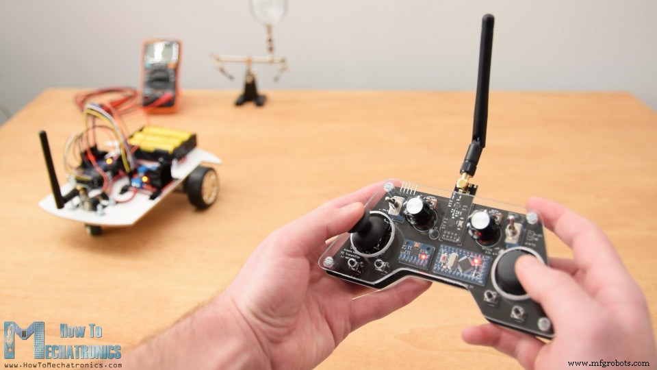
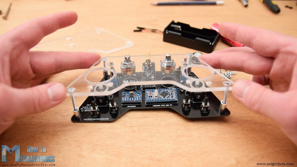
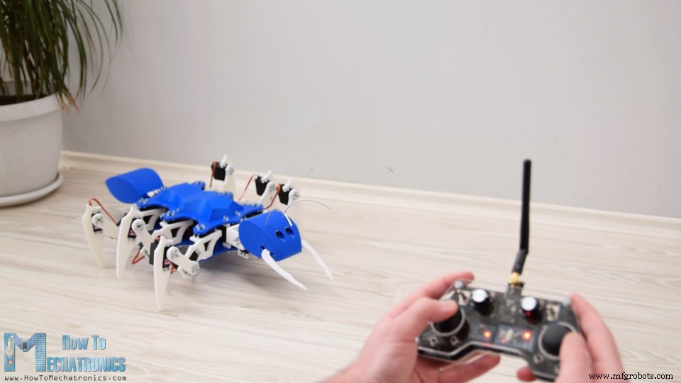
튜토리얼에서 우리는 DIY Arduino RC 송신기를 만드는 방법을 배울 것입니다. 종종 내가 만드는 프로젝트에 무선 제어가 필요하므로 거의 모든 작업에 사용할 수 있는 이 다기능 라디오 컨트롤러를 만들었습니다.
다음 비디오를 보거나 아래에 작성된 튜토리얼을 읽을 수 있습니다.
이제 수신기 측에서 약간의 조정만 하면 모든 Arduino 프로젝트를 무선으로 제어할 수 있습니다. 이 송신기는 RC 장난감, 자동차, 드론 등을 제어하기 위한 상업용 RC 송신기로도 사용할 수 있습니다. 이를 위해서는 상용 RC 장치를 제어하기 위한 적절한 신호를 생성하는 간단한 Arduino 수신기만 있으면 됩니다.
이 비디오에서는 Arduino 로봇 자동차를 제어하는 몇 가지 예를 통해 모든 것이 어떻게 작동하는지 설명하고 이전 비디오에서 Arduino Ant Robot을 제어하고 ESC와 일부 서보 모터를 사용하여 브러시리스 DC 모터를 제어합니다.
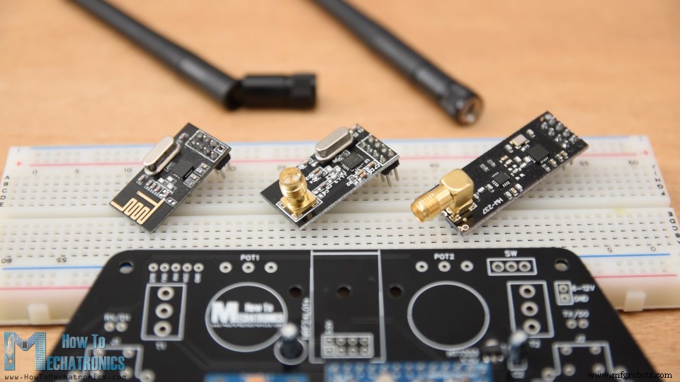
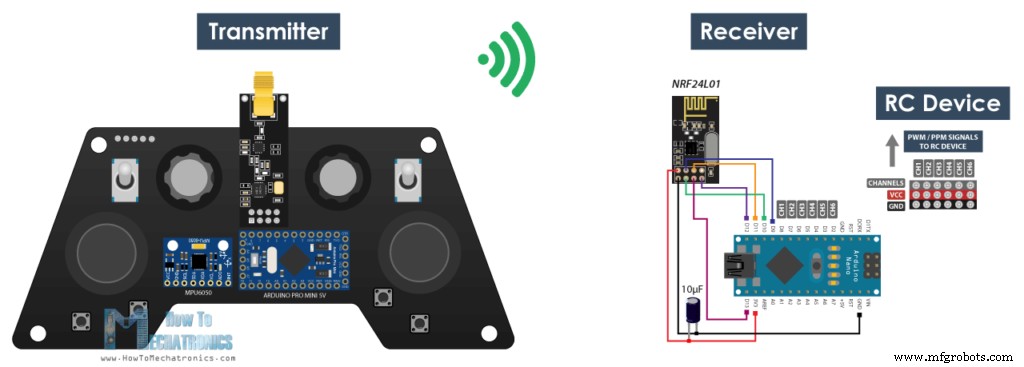
이 컨트롤러의 무선 통신은 NRF24L01 트랜시버 모듈을 기반으로 하며 증폭 안테나와 함께 사용하면 열린 공간에서 최대 700미터의 안정적인 범위를 가질 수 있습니다. 14개의 채널이 있으며 그 중 6개는 아날로그 입력이고 8개는 디지털 입력입니다.
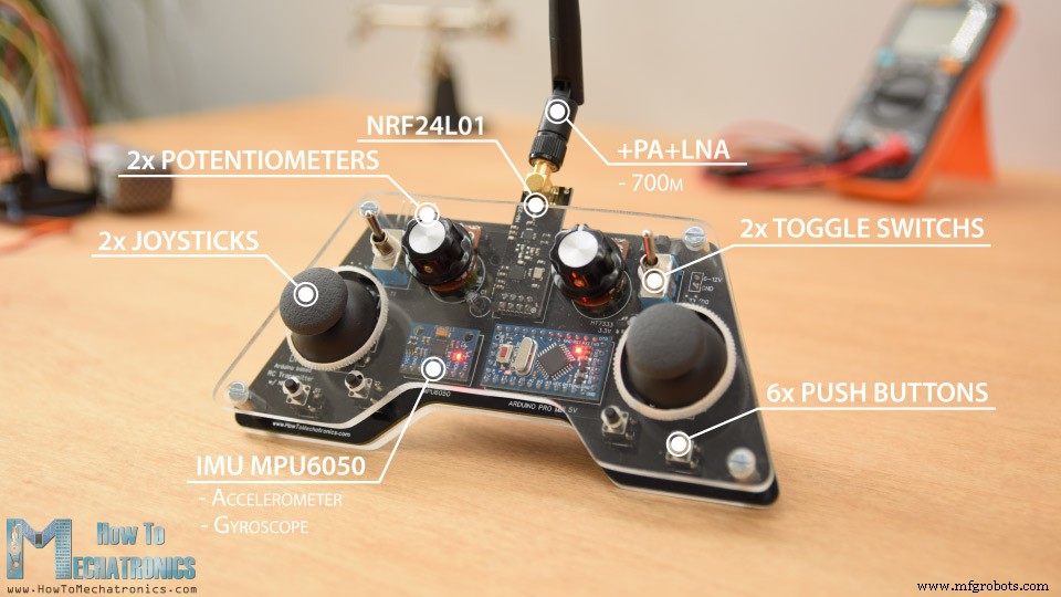
2개의 조이스틱, 2개의 전위차계, 2개의 토글 스위치, 6개의 버튼 및 추가로 컨트롤러를 움직이거나 기울이는 것만으로 사물을 제어하는 데 사용할 수 있는 가속도계와 자이로스코프로 구성된 내부 측정 장치가 있습니다.
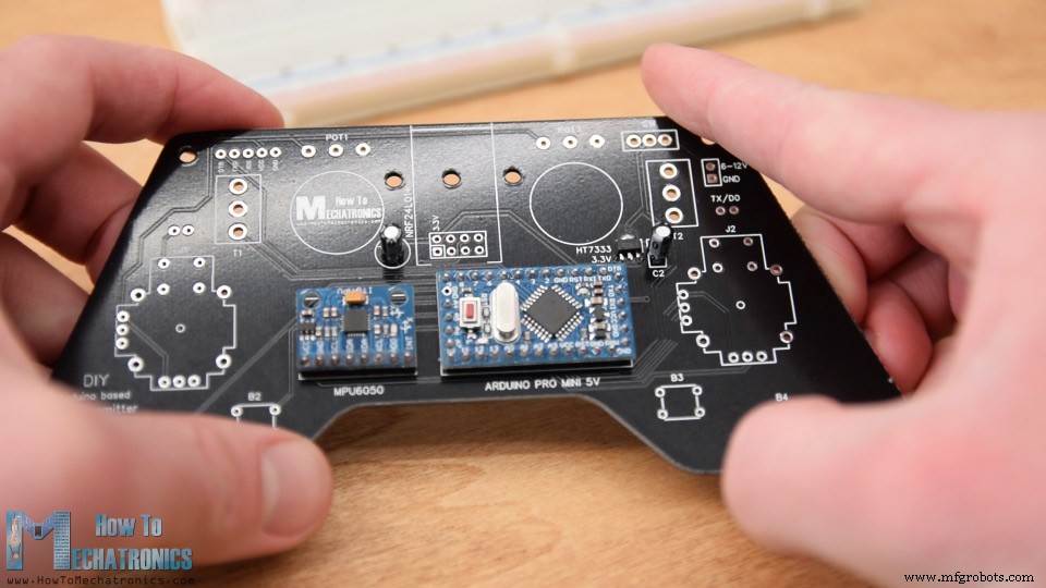
먼저 회로도를 살펴보겠습니다. 이 RC 컨트롤러의 두뇌는 약 7.4볼트를 생성하는 2개의 LiPo 배터리를 사용하여 전원이 공급되는 Arduino Pro Mini입니다. 전압을 5V로 낮추는 전압 조정기가 있는 Pro Mini의 RAW 핀에 직접 연결할 수 있습니다. Arduino Pro Mini에는 5V에서 작동하는 것과 3.3V에서 작동하는 것과 같이 두 가지 버전이 있습니다.
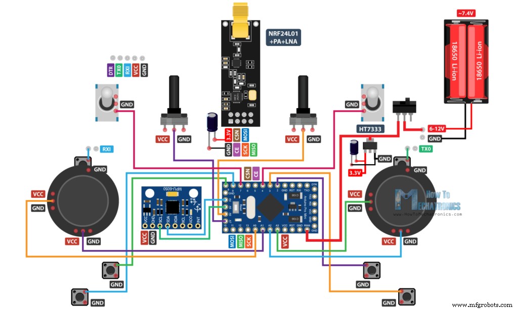
반면에 NRF24L01 모듈은 3.3V가 엄격히 필요하며 전용 소스에서 오는 것이 좋습니다. 따라서 배터리에 연결된 3.3V 전압 조정기를 사용하고 7.4V를 3.3V로 변환해야 합니다. 또한 전압을 더 안정적으로 유지하기 위해 모듈 바로 옆에 디커플링 커패시터를 사용해야 하므로 무선 통신도 더 안정적입니다. NRF24L01 모듈은 SPI 프로토콜을 사용하여 Arduino와 통신하고 MPU6050 가속도계 및 자이로 모듈은 I2C 프로토콜을 사용합니다.
아래 링크에서 이 Arduino 튜토리얼에 필요한 구성요소를 얻을 수 있습니다.
나는 실제로 Arduino Pro Mini의 모든 아날로그 및 디지털 핀을 활용하게 되었습니다. 이제 점프 와이어를 사용하여 모든 것을 함께 연결하려고 하면 상당히 엉망이 될 것입니다. 그래서 EasyEDA 무료 온라인 회로 설계 소프트웨어를 사용하여 맞춤형 PCB를 설계했습니다.
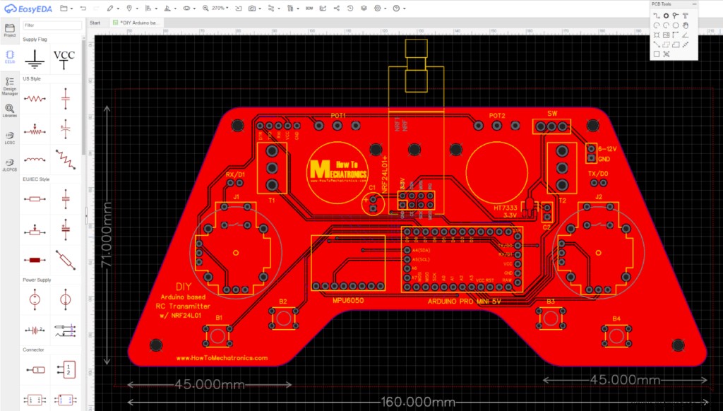
여기에서는 컨트롤러의 인체 공학을 고려하여 두 손으로 쉽게 잡을 수 있도록 설계했으며 모든 컨트롤은 손가락 범위 내에 있습니다. 나는 가장자리를 둥글게 만들고 3mm 구멍을 추가하여 나중에 PCB를 무언가에 장착할 수 있습니다. Arduino를 다시 프로그래밍하려는 경우 쉽게 액세스할 수 있도록 컨트롤러 상단에 Arduino Pro Mini 프로그래밍용 핀을 배치했습니다. 여기에서 조이스틱 버튼에 Arduino의 RX 및 TX 핀을 사용했음을 알 수 있습니다. 그러나 스케치를 Arduino에 업로드하는 동안 이 두 줄은 무엇이든 연결 해제해야 합니다. 따라서 간단한 점퍼 캡을 사용하여 쉽게 연결할 수 있는 두 개의 핀으로 차단됩니다.
참고: PCB를 가공하거나 그에 따라 PCB 설계를 수정하는 데 적합한 Arduino Pro Mini 버전이 있는지 확인하십시오. 다음은 Arduino와 전압 조정기에 따라 세 가지 버전 간의 비교 사진입니다.
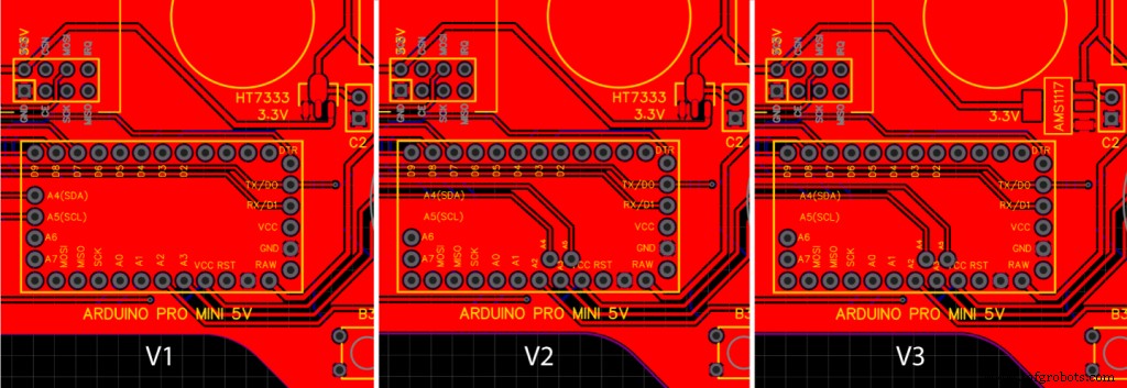
다음은 이 PCB 설계의 프로젝트 파일에 대한 링크입니다. 이렇게 하면 세 가지 다른 버전이 별도의 탭에 열리므로 필요한 것을 선택할 수 있습니다.
그래서 디자인이 끝나면 PCB 제작에 필요한 Gerber 파일을 생성했습니다.
거버 파일:
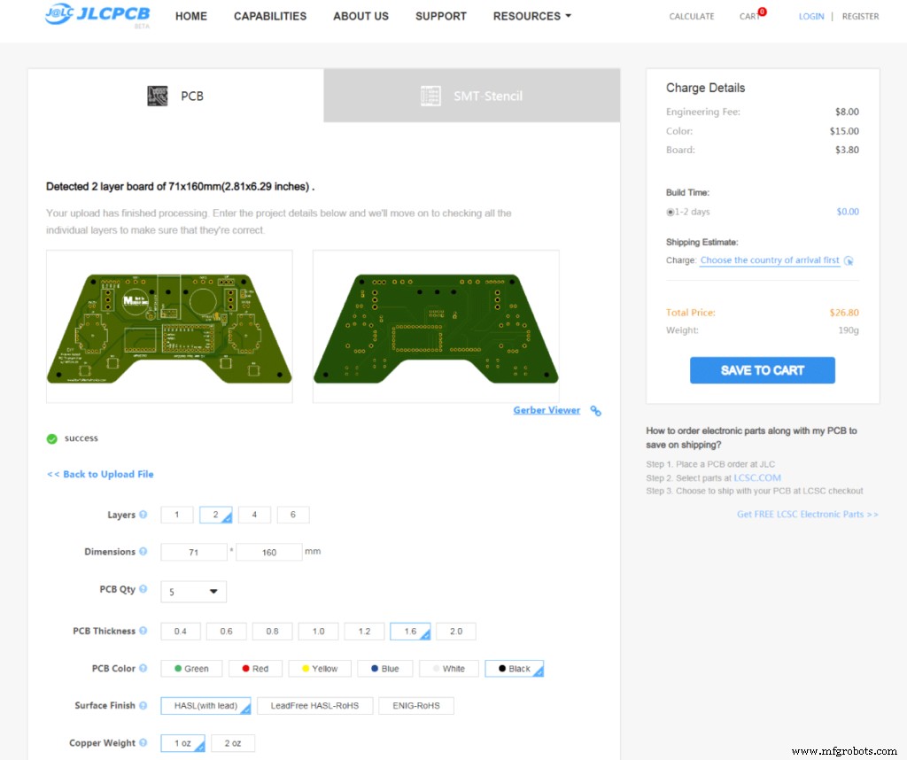
그리고 이 영상의 스폰서이기도 한 JLCPCB에서 PCB를 주문했습니다.

여기에서 Gerber 파일을 간단히 끌어다 놓을 수 있으며 업로드되면 Gerber 뷰어에서 PCB를 검토할 수 있습니다. 모든 것이 정상이면 계속해서 PCB에 대해 원하는 속성을 선택할 수 있습니다. 이번에는 PCB 색상을 검정색으로 선택했습니다. 이제 우리는 합리적인 가격에 PCB를 주문할 수 있습니다. JLCPCB에서 처음 주문하는 경우 단돈 2달러에 최대 10개의 PCB를 얻을 수 있습니다.
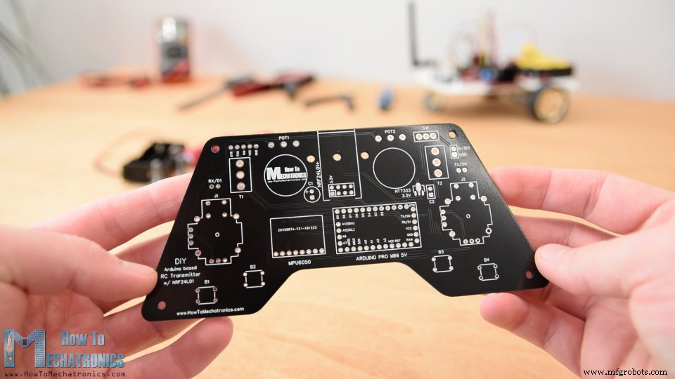
여기 있습니다. 나는 이 PCB가 이 검은색으로 어떻게 나왔는지 정말 좋아합니다. PCB의 품질이 우수하고 모든 것이 디자인과 동일합니다.
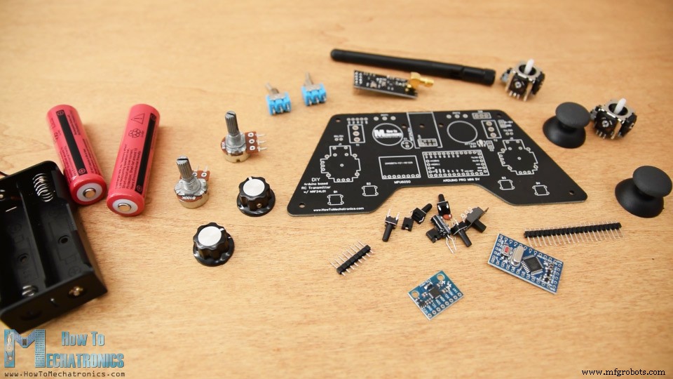
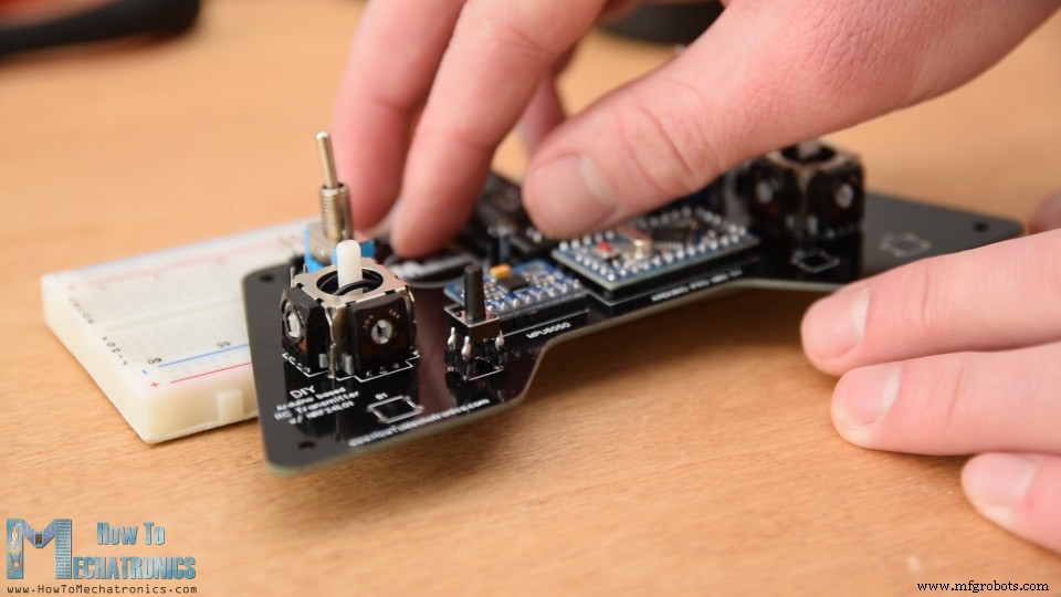
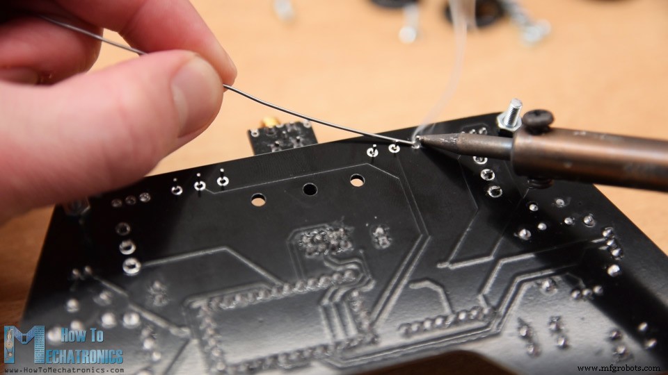
이제 PCB 조립을 진행할 수 있습니다. Arduino Pro Mini의 핀 헤더를 납땜하는 것으로 시작했습니다. 이를 수행하는 쉽고 좋은 방법은 브레드보드에 올려서 납땜하는 동안 제자리에 단단히 고정되도록 하는 것입니다.
Pro Mini의 측면에도 핀이 있지만 이러한 핀 위치는 제조업체에 따라 다를 수 있습니다.
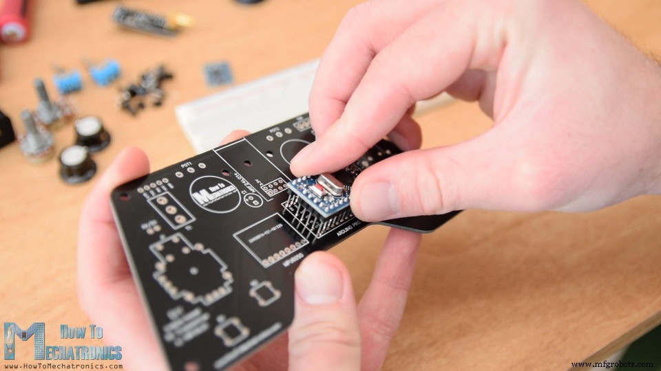
내가 가지고 있는 특정 모델의 경우 각 면에 5개의 핀이 필요하고 일부 트레이스를 실행하기 위해 PCB 아래 영역을 사용했기 때문에 하나의 GND 핀은 비워 둡니다. Arduino Pro Mini를 PCB에 직접 납땜하고 헤더의 exec 길이를 자릅니다. 바로 옆에는 MPU6050 가속도계와 자이로스코프 모듈이 있습니다.
그런 다음 옆에 커패시터가 있는 3.3V 전압 레귤레이터를 납땜하고 NRF24L01 모듈 근처에 다른 커패시터를 납땜했습니다. 이 모듈에는 세 가지 다른 버전이 있으며 여기에서 어떤 버전이든 사용할 수 있습니다.
Arduino 프로그래밍용 핀, RX 및 TX 핀, 전원 공급 장치 핀 및 전원 스위치를 계속 사용했습니다.
다음으로 전위차계를 PCB에 납땜하기 위해 일부 핀 헤더를 사용하여 핀을 확장해야 했습니다.
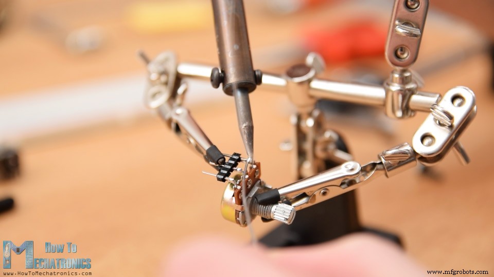
여기에서 이전에 손잡이의 길이를 잘라서 일부 캡을 적절하게 맞출 수 있음을 알 수 있습니다. 그러나 잠시 후에 전위차계를 PCB에 납땜할 것입니다.
그런 다음 두 개의 토글 스위치와 두 개의 조이스틱을 제자리에 삽입하고 납땜했습니다.
마지막으로 남은 것은 4개의 푸시 버튼을 납땜하는 것입니다. 그러나 높이가 적절하지 않아 다시 핀 헤더를 사용하여 핀을 약간 늘렸습니다.
이제 PCB가 준비되었으므로 계속해서 덮개를 만들 수 있습니다. PCB의 모양이 마음에 들고 눈에 띄고 싶기 때문에 커버에 투명 아크릴을 사용하기로 결정했습니다.
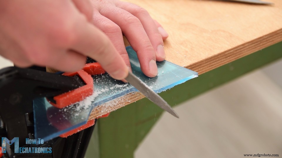
여기에 현재 보호 호일이 있고 파란색으로 보이는 4mm 눈금 투명 아크릴이 있습니다. 커버의 아이디어는 PCB 모양으로 두 개의 판을 만들어 하나는 PCB의 상단에 고정하고 다른 하나는 하단에 고정하는 것입니다.
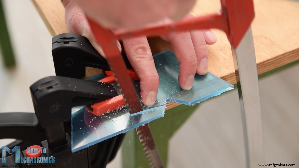
그래서 PCB 모양을 표시하고 금속 손톱을 사용하여 아크릴을 그에 맞게 자릅니다.
그런 다음 간단한 줄을 사용하여 아크릴의 모양을 미세 조정했습니다. 두 개의 플레이트가 멋지게 나왔고 PCB와 완벽하게 일치합니다.
다음으로 구성 요소가 통과할 구멍을 만들어야 하는 위치를 표시했습니다. 3mm 드릴을 사용하여 먼저 플레이트를 PCB에 고정하기 위한 4개의 구멍을 만들었습니다. 이 구멍의 경우 볼트가 플레이트와 함께 플래시 위치에 놓일 수 있도록 카운터 싱크도 만들었습니다.
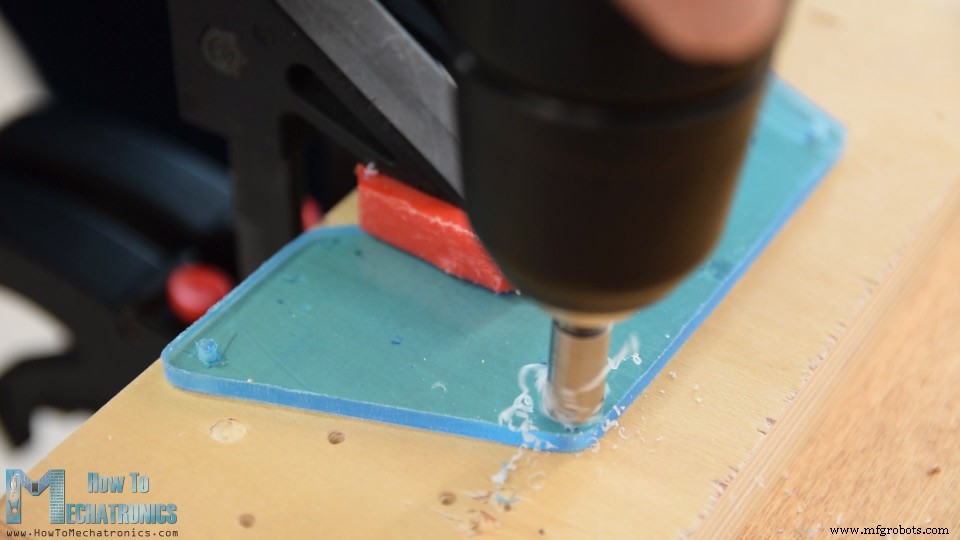
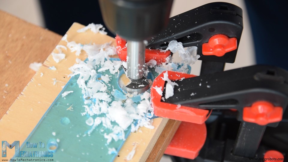
토글 스위치와 전위차계의 구멍에는 6mm 드릴을 사용하고 조이스틱 구멍에는 25mm Forstner 비트를 사용했습니다. 다시 말하지만, 나는 줄을 사용하여 모든 개구부를 미세 조정했습니다.
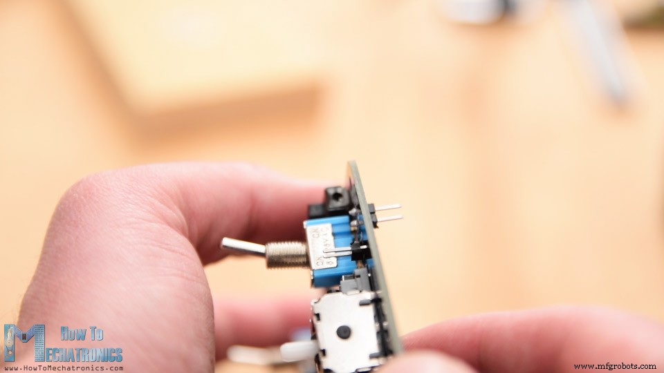
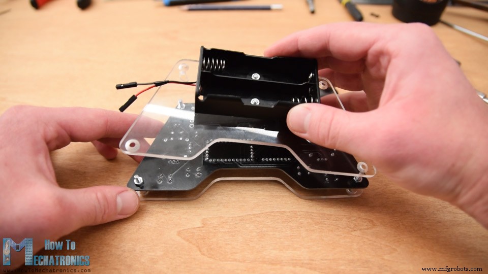
커버를 조립하기 전에 배터리가 위치할 후면에서 닿을 수 있도록 실제로 전원 공급 장치용 핀 헤더를 거꾸로 납땜했습니다.
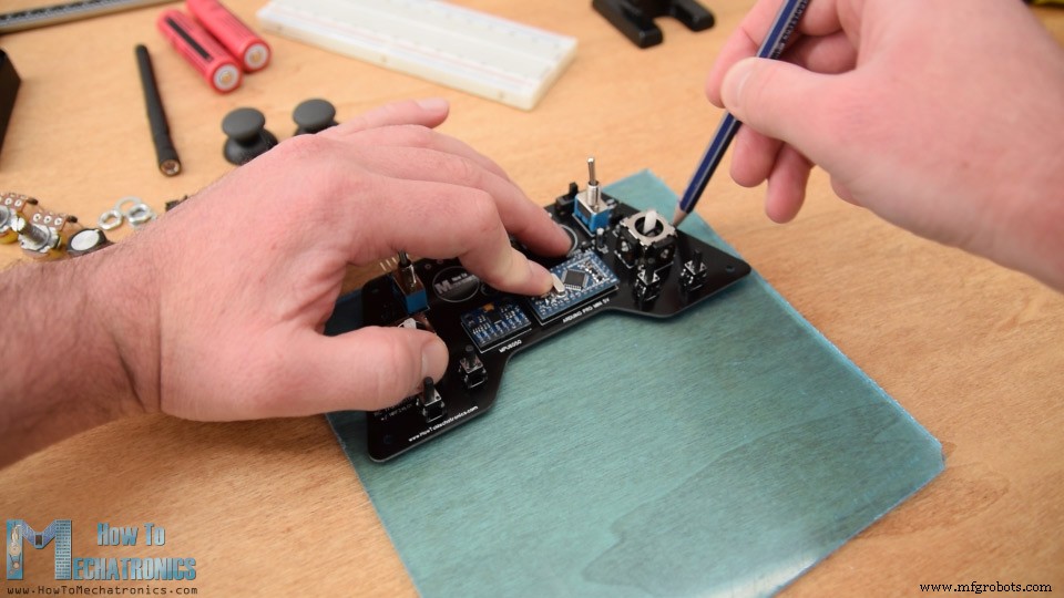
이제 커버 조립을 시작할 수 있습니다. 나는 아크릴에서 보호 호일을 벗기는 것으로 시작했는데 아크릴이 이제 너무 깨끗했기 때문에 꽤 만족스러웠다는 것을 인정해야 합니다. 그래서 먼저 상판에 2개의 전위차계를 고정하고 3mm 마운팅 볼트를 삽입하고 11mm 거리 링을 제자리에 배치했습니다.
그런 다음 몇 개의 볼트를 사용하여 상단 플레이트와 PCB를 조심스럽게 결합하고 고정했습니다. 이 시점에서 나는 전위차계가 어느 높이에 배치될지 정확히 알지 못했기 때문에 마침내 전위차계를 PCB에 납땜했습니다.
다음으로 백 플레이트에 2개의 볼트를 사용하여 배터리 홀더를 부착했습니다. 4개의 마운팅볼트를 이용하여 PCB 뒷면에 백플레이트를 고정하여 커버조립을 완성하였습니다.
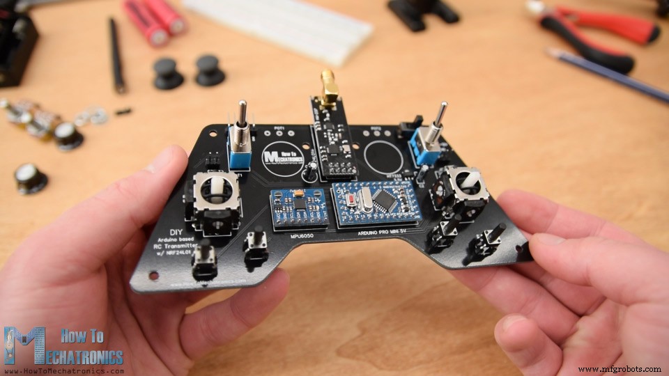
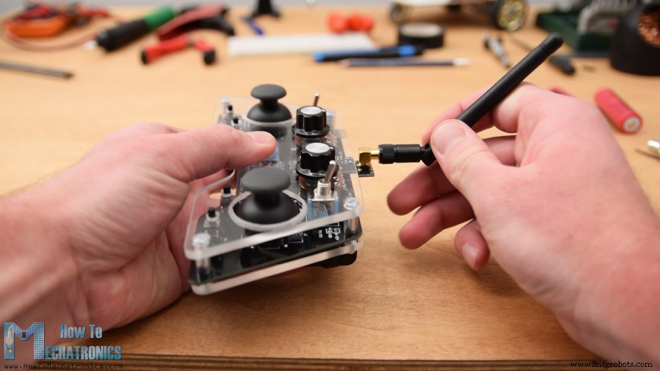
마지막으로 배터리 라인을 전원 공급 장치 핀에 연결하고, 전위차계에 손잡이를 삽입 및 고정하고, 조이스틱 손잡이를 삽입하고 안테나를 NRF24l01 모듈에 부착할 수 있습니다. 드디어 DIY Arduino RC 송신기가 완성되었습니다.
이제 남은 것은 Arduino를 프로그래밍하는 것입니다. Pro Mini 보드를 프로그래밍하려면 컨트롤러 상단에 있는 프로그래밍 헤더에 연결할 수 있는 USB-직렬 UART 인터페이스가 필요합니다.
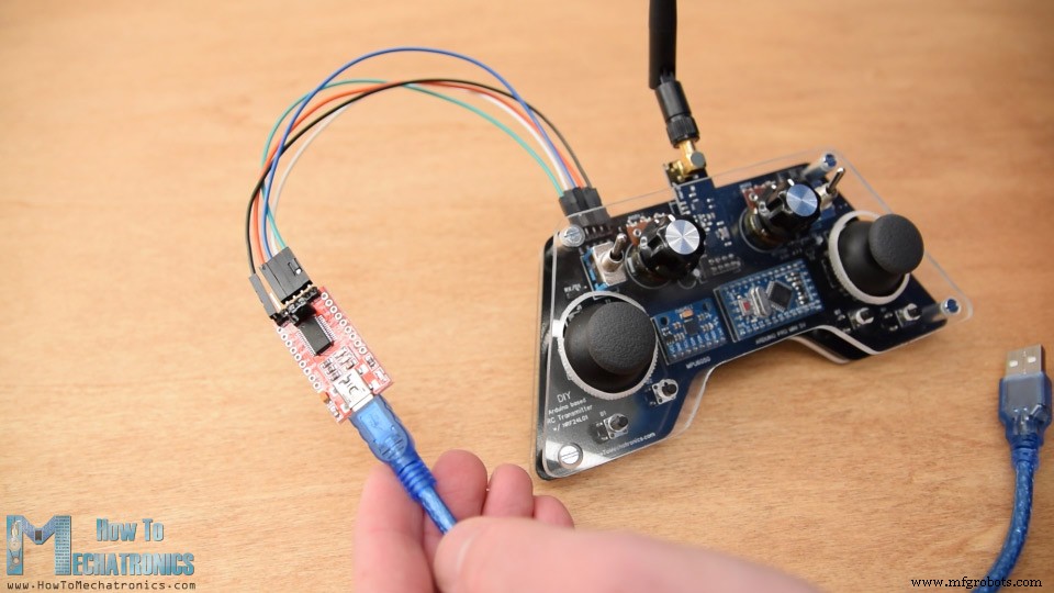
그런 다음 Arduino IDE 도구 메뉴에서 Arduino Pro 또는 Pro Mini 보드를 선택하고 적절한 프로세서 버전을 선택하고 포트를 선택하고 프로그래밍 방법을 "USBasp"로 선택해야 합니다.
<그림 클래스="aligncenter">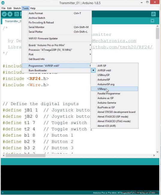
이제 Arduino에 코드를 업로드할 수 있습니다.
송신기 코드가 어떻게 작동하는지 설명하겠습니다. 따라서 먼저 무선 통신을 위한 SPI 및 RF24 라이브러리와 가속도계 모듈을 위한 I2C 라이브러리를 포함해야 합니다. 그런 다음 디지털 입력, 아래 프로그램에 필요한 일부 변수, 라디오 개체 및 통신 주소를 정의해야 합니다.
#include <SPI.h>
#include <nRF24L01.h>
#include <RF24.h>
#include <Wire.h>


// Define the digital inputs
#define jB1 1  // Joystick button 1
#define jB2 0  // Joystick button 2
#define t1 7   // Toggle switch 1
#define t2 4   // Toggle switch 1
#define b1 8   // Button 1
#define b2 9   // Button 2
#define b3 2   // Button 3
#define b4 3   // Button 4

const int MPU = 0x68; // MPU6050 I2C address
float AccX, AccY, AccZ;
float GyroX, GyroY, GyroZ;
float accAngleX, accAngleY, gyroAngleX, gyroAngleY;
float angleX, angleY;
float AccErrorX, AccErrorY, GyroErrorX, GyroErrorY;
float elapsedTime, currentTime, previousTime;
int c = 0;


RF24 radio(5, 6);   // nRF24L01 (CE, CSN)
const byte address[6] = "00001"; // AddressCode language: Arduino (arduino)
그런 다음 컨트롤러의 14개 입력 값을 저장할 구조를 정의해야 합니다. 이 구조의 최대 크기는 NRF24L01 버퍼 제한 또는 모듈이 한 번에 보낼 수 있는 데이터 양이기 때문에 32바이트일 수 있습니다.
/ Max size of this struct is 32 bytes - NRF24L01 buffer limit
struct Data_Package {
  byte j1PotX;
  byte j1PotY;
  byte j1Button;
  byte j2PotX;
  byte j2PotY;
  byte j2Button;
  byte pot1;
  byte pot2;
  byte tSwitch1;
  byte tSwitch2;
  byte button1;
  byte button2;
  byte button3;
  byte button4;
};

Data_Package data; //Create a variable with the above structureCode language: Arduino (arduino)
설정 섹션에서 MPU6050 모듈을 초기화해야 하며 나중에 모듈의 올바른 각도를 계산할 때 사용되는 값인 IMU 오류도 계산할 수 있습니다.
void initialize_MPU6050() {
  Wire.begin();                      // Initialize comunication
  Wire.beginTransmission(MPU);       // Start communication with MPU6050 // MPU=0x68
  Wire.write(0x6B);                  // Talk to the register 6B
  Wire.write(0x00);                  // Make reset - place a 0 into the 6B register
  Wire.endTransmission(true);        //end the transmission
  // Configure Accelerometer
  Wire.beginTransmission(MPU);
  Wire.write(0x1C);                  //Talk to the ACCEL_CONFIG register
  Wire.write(0x10);                  //Set the register bits as 00010000 (+/- 8g full scale range)
  Wire.endTransmission(true);
  // Configure Gyro
  Wire.beginTransmission(MPU);
  Wire.write(0x1B);                   // Talk to the GYRO_CONFIG register (1B hex)
  Wire.write(0x10);                   // Set the register bits as 00010000 (1000dps full scale)
  Wire.endTransmission(true);
}Code language: Arduino (arduino)
MEMS 가속도계 및 자이로 작동 방식에 대한 자세한 내용은 여기에서 확인할 수 있습니다. MPU6050 전용 튜토리얼이 곧 제공될 예정입니다.
그런 다음 무선 통신을 초기화하고 모든 디지털 입력에 대해 Arduino 내부 풀업 저항을 활성화하고 모든 변수에 대해 초기 기본값을 설정해야 합니다.
// Define the radio communication
  radio.begin();
  radio.openWritingPipe(address);
  radio.setAutoAck(false);
  radio.setDataRate(RF24_250KBPS);
  radio.setPALevel(RF24_PA_LOW);

  // Activate the Arduino internal pull-up resistors
  pinMode(jB1, INPUT_PULLUP);
  pinMode(jB2, INPUT_PULLUP);
  pinMode(t1, INPUT_PULLUP);
  pinMode(t2, INPUT_PULLUP);
  pinMode(b1, INPUT_PULLUP);
  pinMode(b2, INPUT_PULLUP);
  pinMode(b3, INPUT_PULLUP);
  pinMode(b4, INPUT_PULLUP);Code language: Arduino (arduino)
루프 섹션에서 모든 아날로그 입력을 읽는 것으로 시작하고 0에서 1023까지의 값을 0에서 255까지의 바이트 값으로 매핑합니다. 왜냐하면 우리는 이미 구조의 변수를 바이트로 정의했기 때문입니다. 각 입력은 구조의 특정 데이터 변수에 저장됩니다.
// Read all analog inputs and map them to one Byte value
  data.j1PotX = map(analogRead(A1), 0, 1023, 0, 255); // Convert the analog read value from 0 to 1023 into a BYTE value from 0 to 255
  data.j1PotY = map(analogRead(A0), 0, 1023, 0, 255);
  data.j2PotX = map(analogRead(A2), 0, 1023, 0, 255);
  data.j2PotY = map(analogRead(A3), 0, 1023, 0, 255);
  data.pot1 = map(analogRead(A7), 0, 1023, 0, 255);
  data.pot2 = map(analogRead(A6), 0, 1023, 0, 255);Code language: Arduino (arduino)
풀업 저항을 사용하기 때문에 버튼을 눌렀을 때 디지털 핀 판독값이 0이라는 점에 유의해야 합니다.
// Read all digital inputs
  data.j1Button = digitalRead(jB1);
  data.j2Button = digitalRead(jB2);
  data.tSwitch2 = digitalRead(t2);
  data.button1 = digitalRead(b1);
  data.button2 = digitalRead(b2);
  data.button3 = digitalRead(b3);
  data.button4 = digitalRead(b4);Code language: Arduino (arduino)
따라서 radio.write() 함수를 사용하여 모든 14개 채널의 값을 수신기로 간단히 보냅니다.
// Send the whole data from the structure to the receiver
  radio.write(&data, sizeof(Data_Package));Code language: Arduino (arduino)
토글 스위치 1이 켜져 있는 경우 제어 대신 가속도계와 자이로 데이터를 사용합니다.
if (digitalRead(t1) == 0) {
    read_IMU();    // Use MPU6050 instead of Joystick 1 for controling left, right, forward and backward movements
  }Code language: Arduino (arduino)
따라서 조이스틱 1 X 및 Y 값 대신에 IMU에서 가져온 각도 값을 사용하고 있습니다. 이 값은 이전에 -90도에서 +90도 값을 0에서 255도 사이의 바이트 값으로 적절하게 변환했습니다.
// Map the angle values from -90deg to +90 deg into values from 0 to 255, like the values we are getting from the Joystick
  data.j1PotX = map(angleX, -90, +90, 255, 0);
  data.j1PotY = map(angleY, -90, +90, 0, 255);Code language: Arduino (arduino)
그래서 송신기 코드, 가장 중요한 것은 무선 통신을 정의하고 데이터를 수신기로 보내는 것입니다.
이 DIY Arduino RC 송신기의 전체 Arduino 코드는 다음과 같습니다.
/*
        DIY Arduino based RC Transmitter
  by Dejan Nedelkovski, www.HowToMechatronics.com
  Library: TMRh20/RF24, https://github.com/tmrh20/RF24/
*/

#include <SPI.h>
#include <nRF24L01.h>
#include <RF24.h>
#include <Wire.h>


// Define the digital inputs
#define jB1 1  // Joystick button 1
#define jB2 0  // Joystick button 2
#define t1 7   // Toggle switch 1
#define t2 4   // Toggle switch 1
#define b1 8   // Button 1
#define b2 9   // Button 2
#define b3 2   // Button 3
#define b4 3   // Button 4

const int MPU = 0x68; // MPU6050 I2C address
float AccX, AccY, AccZ;
float GyroX, GyroY, GyroZ;
float accAngleX, accAngleY, gyroAngleX, gyroAngleY;
float angleX, angleY;
float AccErrorX, AccErrorY, GyroErrorX, GyroErrorY;
float elapsedTime, currentTime, previousTime;
int c = 0;


RF24 radio(5, 6);   // nRF24L01 (CE, CSN)
const byte address[6] = "00001"; // Address

// Max size of this struct is 32 bytes - NRF24L01 buffer limit
struct Data_Package {
  byte j1PotX;
  byte j1PotY;
  byte j1Button;
  byte j2PotX;
  byte j2PotY;
  byte j2Button;
  byte pot1;
  byte pot2;
  byte tSwitch1;
  byte tSwitch2;
  byte button1;
  byte button2;
  byte button3;
  byte button4;
};

Data_Package data; //Create a variable with the above structure

void setup() {
  Serial.begin(9600);

  // Initialize interface to the MPU6050
  initialize_MPU6050();

  // Call this function if you need to get the IMU error values for your module
  //calculate_IMU_error();

  // Define the radio communication
  radio.begin();
  radio.openWritingPipe(address);
  radio.setAutoAck(false);
  radio.setDataRate(RF24_250KBPS);
  radio.setPALevel(RF24_PA_LOW);

  // Activate the Arduino internal pull-up resistors
  pinMode(jB1, INPUT_PULLUP);
  pinMode(jB2, INPUT_PULLUP);
  pinMode(t1, INPUT_PULLUP);
  pinMode(t2, INPUT_PULLUP);
  pinMode(b1, INPUT_PULLUP);
  pinMode(b2, INPUT_PULLUP);
  pinMode(b3, INPUT_PULLUP);
  pinMode(b4, INPUT_PULLUP);

  // Set initial default values
  data.j1PotX = 127; // Values from 0 to 255. When Joystick is in resting position, the value is in the middle, or 127. We actually map the pot value from 0 to 1023 to 0 to 255 because that's one BYTE value
  data.j1PotY = 127;
  data.j2PotX = 127;
  data.j2PotY = 127;
  data.j1Button = 1;
  data.j2Button = 1;
  data.pot1 = 1;
  data.pot2 = 1;
  data.tSwitch1 = 1;
  data.tSwitch2 = 1;
  data.button1 = 1;
  data.button2 = 1;
  data.button3 = 1;
  data.button4 = 1;
}
void loop() {
  // Read all analog inputs and map them to one Byte value
  data.j1PotX = map(analogRead(A1), 0, 1023, 0, 255); // Convert the analog read value from 0 to 1023 into a BYTE value from 0 to 255
  data.j1PotY = map(analogRead(A0), 0, 1023, 0, 255);
  data.j2PotX = map(analogRead(A2), 0, 1023, 0, 255);
  data.j2PotY = map(analogRead(A3), 0, 1023, 0, 255);
  data.pot1 = map(analogRead(A7), 0, 1023, 0, 255);
  data.pot2 = map(analogRead(A6), 0, 1023, 0, 255);
  // Read all digital inputs
  data.j1Button = digitalRead(jB1);
  data.j2Button = digitalRead(jB2);
  data.tSwitch2 = digitalRead(t2);
  data.button1 = digitalRead(b1);
  data.button2 = digitalRead(b2);
  data.button3 = digitalRead(b3);
  data.button4 = digitalRead(b4);
  // If toggle switch 1 is switched on
  if (digitalRead(t1) == 0) {
    read_IMU();    // Use MPU6050 instead of Joystick 1 for controling left, right, forward and backward movements
  }
  // Send the whole data from the structure to the receiver
  radio.write(&data, sizeof(Data_Package));
}

void initialize_MPU6050() {
  Wire.begin();                      // Initialize comunication
  Wire.beginTransmission(MPU);       // Start communication with MPU6050 // MPU=0x68
  Wire.write(0x6B);                  // Talk to the register 6B
  Wire.write(0x00);                  // Make reset - place a 0 into the 6B register
  Wire.endTransmission(true);        //end the transmission
  // Configure Accelerometer
  Wire.beginTransmission(MPU);
  Wire.write(0x1C);                  //Talk to the ACCEL_CONFIG register
  Wire.write(0x10);                  //Set the register bits as 00010000 (+/- 8g full scale range)
  Wire.endTransmission(true);
  // Configure Gyro
  Wire.beginTransmission(MPU);
  Wire.write(0x1B);                   // Talk to the GYRO_CONFIG register (1B hex)
  Wire.write(0x10);                   // Set the register bits as 00010000 (1000dps full scale)
  Wire.endTransmission(true);
}

void calculate_IMU_error() {
  // We can call this funtion in the setup section to calculate the accelerometer and gury data error. From here we will get the error values used in the above equations printed on the Serial Monitor.
  // Note that we should place the IMU flat in order to get the proper values, so that we then can the correct values
  // Read accelerometer values 200 times
  while (c < 200) {
    Wire.beginTransmission(MPU);
    Wire.write(0x3B);
    Wire.endTransmission(false);
    Wire.requestFrom(MPU, 6, true);
    AccX = (Wire.read() << 8 | Wire.read()) / 4096.0 ;
    AccY = (Wire.read() << 8 | Wire.read()) / 4096.0 ;
    AccZ = (Wire.read() << 8 | Wire.read()) / 4096.0 ;
    // Sum all readings
    AccErrorX = AccErrorX + ((atan((AccY) / sqrt(pow((AccX), 2) + pow((AccZ), 2))) * 180 / PI));
    AccErrorY = AccErrorY + ((atan(-1 * (AccX) / sqrt(pow((AccY), 2) + pow((AccZ), 2))) * 180 / PI));
    c++;
  }
  //Divide the sum by 200 to get the error value
  AccErrorX = AccErrorX / 200;
  AccErrorY = AccErrorY / 200;
  c = 0;
  // Read gyro values 200 times
  while (c < 200) {
    Wire.beginTransmission(MPU);
    Wire.write(0x43);
    Wire.endTransmission(false);
    Wire.requestFrom(MPU, 4, true);
    GyroX = Wire.read() << 8 | Wire.read();
    GyroY = Wire.read() << 8 | Wire.read();
    // Sum all readings
    GyroErrorX = GyroErrorX + (GyroX / 32.8);
    GyroErrorY = GyroErrorY + (GyroY / 32.8);
    c++;
  }
  //Divide the sum by 200 to get the error value
  GyroErrorX = GyroErrorX / 200;
  GyroErrorY = GyroErrorY / 200;
  // Print the error values on the Serial Monitor
  Serial.print("AccErrorX: ");
  Serial.println(AccErrorX);
  Serial.print("AccErrorY: ");
  Serial.println(AccErrorY);
  Serial.print("GyroErrorX: ");
  Serial.println(GyroErrorX);
  Serial.print("GyroErrorY: ");
  Serial.println(GyroErrorY);
}

void read_IMU() {
  // === Read acceleromter data === //
  Wire.beginTransmission(MPU);
  Wire.write(0x3B); // Start with register 0x3B (ACCEL_XOUT_H)
  Wire.endTransmission(false);
  Wire.requestFrom(MPU, 6, true); // Read 6 registers total, each axis value is stored in 2 registers
  //For a range of +-8g, we need to divide the raw values by 4096, according to the datasheet
  AccX = (Wire.read() << 8 | Wire.read()) / 4096.0; // X-axis value
  AccY = (Wire.read() << 8 | Wire.read()) / 4096.0; // Y-axis value
  AccZ = (Wire.read() << 8 | Wire.read()) / 4096.0; // Z-axis value

  // Calculating angle values using
  accAngleX = (atan(AccY / sqrt(pow(AccX, 2) + pow(AccZ, 2))) * 180 / PI) + 1.15; // AccErrorX ~(-1.15) See the calculate_IMU_error()custom function for more details
  accAngleY = (atan(-1 * AccX / sqrt(pow(AccY, 2) + pow(AccZ, 2))) * 180 / PI) - 0.52; // AccErrorX ~(0.5)

  // === Read gyro data === //
  previousTime = currentTime;        // Previous time is stored before the actual time read
  currentTime = millis();            // Current time actual time read
  elapsedTime = (currentTime - previousTime) / 1000;   // Divide by 1000 to get seconds
  Wire.beginTransmission(MPU);
  Wire.write(0x43); // Gyro data first register address 0x43
  Wire.endTransmission(false);
  Wire.requestFrom(MPU, 4, true); // Read 4 registers total, each axis value is stored in 2 registers
  GyroX = (Wire.read() << 8 | Wire.read()) / 32.8; // For a 1000dps range we have to divide first the raw value by 32.8, according to the datasheet
  GyroY = (Wire.read() << 8 | Wire.read()) / 32.8;
  GyroX = GyroX + 1.85; //// GyroErrorX ~(-1.85)
  GyroY = GyroY - 0.15; // GyroErrorY ~(0.15)
  // Currently the raw values are in degrees per seconds, deg/s, so we need to multiply by sendonds (s) to get the angle in degrees
  gyroAngleX = GyroX * elapsedTime;
  gyroAngleY = GyroY * elapsedTime;

  // Complementary filter - combine acceleromter and gyro angle values
  angleX = 0.98 * (angleX + gyroAngleX) + 0.02 * accAngleX;
  angleY = 0.98 * (angleY + gyroAngleY) + 0.02 * accAngleY;
  // Map the angle values from -90deg to +90 deg into values from 0 to 255, like the values we are getting from the Joystick
  data.j1PotX = map(angleX, -90, +90, 255, 0);
  data.j1PotY = map(angleY, -90, +90, 0, 255);
}Code language: Arduino (arduino)이제 이 데이터를 수신하는 방법을 살펴보겠습니다. 다음은 간단한 Arduino 및 NRF24L01 수신기 회로도입니다. 물론 다른 아두이노 보드를 사용해도 됩니다.
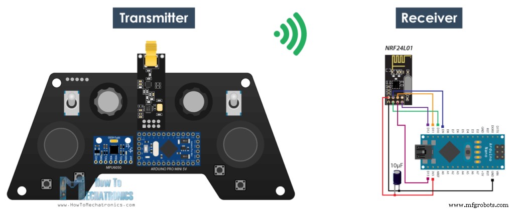
그리고 여기에 우리가 데이터를 수신하고 단순히 통신이 제대로 작동하는지 알 수 있도록 직렬 모니터에 인쇄하는 간단한 수신기 코드가 있습니다. 다시 RF24 라이브러리를 포함하고 송신기 코드에서와 동일한 방식으로 객체와 구조를 정의해야 합니다. 무선 통신을 정의할 때 설정 섹션에서 송신기와 동일한 설정을 사용하고 radio.startListening() 함수를 사용하여 모듈을 수신기로 설정해야 합니다.
/*
    DIY Arduino based RC Transmitter Project
              == Receiver Code ==

  by Dejan Nedelkovski, www.HowToMechatronics.com
  Library: TMRh20/RF24, https://github.com/tmrh20/RF24/
*/
#include <SPI.h>
#include <nRF24L01.h>
#include <RF24.h>
RF24 radio(10, 9);   // nRF24L01 (CE, CSN)
const byte address[6] = "00001";

unsigned long lastReceiveTime = 0;
unsigned long currentTime = 0;

// Max size of this struct is 32 bytes - NRF24L01 buffer limit
struct Data_Package {
  byte j1PotX;
  byte j1PotY;
  byte j1Button;
  byte j2PotX;
  byte j2PotY;
  byte j2Button;
  byte pot1;
  byte pot2;
  byte tSwitch1;
  byte tSwitch2;
  byte button1;
  byte button2;
  byte button3;
  byte button4;
};

Data_Package data; //Create a variable with the above structure

void setup() {
  Serial.begin(9600);
  radio.begin();
  radio.openReadingPipe(0, address);
  radio.setAutoAck(false);
  radio.setDataRate(RF24_250KBPS);
  radio.setPALevel(RF24_PA_LOW);
  radio.startListening(); //  Set the module as receiver
  resetData();
}
void loop() {
  // Check whether there is data to be received
  if (radio.available()) {
    radio.read(&data, sizeof(Data_Package)); // Read the whole data and store it into the 'data' structure
    lastReceiveTime = millis(); // At this moment we have received the data
  }
  // Check whether we keep receving data, or we have a connection between the two modules
  currentTime = millis();
  if ( currentTime - lastReceiveTime > 1000 ) { // If current time is more then 1 second since we have recived the last data, that means we have lost connection
    resetData(); // If connection is lost, reset the data. It prevents unwanted behavior, for example if a drone has a throttle up and we lose connection, it can keep flying unless we reset the values
  }
  // Print the data in the Serial Monitor
  Serial.print("j1PotX: ");
  Serial.print(data.j1PotX);
  Serial.print("; j1PotY: ");
  Serial.print(data.j1PotY);
  Serial.print("; button1: ");
  Serial.print(data.button1);
  Serial.print("; j2PotX: ");
  Serial.println(data.j2PotX);
}

void resetData() {
  // Reset the values when there is no radio connection - Set initial default values
  data.j1PotX = 127;
  data.j1PotY = 127;
  data.j2PotX = 127;
  data.j2PotY = 127;
  data.j1Button = 1;
  data.j2Button = 1;
  data.pot1 = 1;
  data.pot2 = 1;
  data.tSwitch1 = 1;
  data.tSwitch2 = 1;
  data.button1 = 1;
  data.button2 = 1;
  data.button3 = 1;
  data.button4 = 1;
}Code language: Arduino (arduino)
available() 함수를 사용하는 메인 루프에서 들어오는 데이터가 있는지 확인합니다. 참이면 단순히 데이터를 읽고 구조의 변수에 저장합니다. 이제 직렬 모니터에서 데이터를 인쇄하여 전송이 제대로 작동하는지 확인할 수 있습니다. 또한 millis() 함수와 if 문을 사용하여 데이터를 계속 수신하는지 확인하거나 1초 이상 데이터를 수신하지 않으면 변수를 기본값으로 재설정합니다. 예를 들어 드론에 스로틀이 있고 연결이 끊긴 경우 값을 재설정하지 않는 한 드론이 계속 날아갈 수 있는 등 원치 않는 동작을 방지하기 위해 이것을 사용합니다.
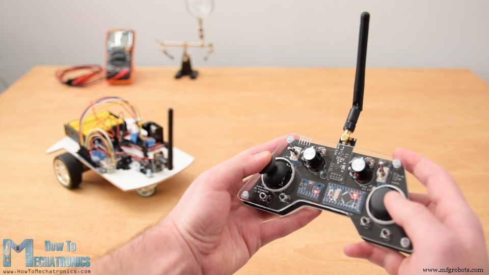
그게 다야. 이제 우리는 모든 Arduino 프로젝트에 대한 데이터를 수신하는 이 방법을 구현할 수 있습니다. 예를 들어 여기 내 이전 비디오 중 하나에서 Arduino 로봇 자동차를 제어하기 위한 코드가 있습니다.
이번 프로젝트의 업데이트로 아두이노 전용 RC 수신기를 만들었습니다. 다시 말하지만 이것은 Arduino Pro 미니 보드를 기반으로 하며 소형 PCB에 배치된 서보 및 ESC 연결을 사용할 준비가 되어 있습니다.
아두이노 코드:
여기서 앞서 설명한 대로 라이브러리, 구조 및 무선 통신을 정의해야 합니다. 그런 다음 메인 루프에서 들어오는 데이터를 읽고 원하는 데이터를 사용하기만 하면 됩니다. 이 경우 차를 운전하기 위해 조이스틱 1 값을 사용합니다.
아두이노 코드:
같은 방법으로 이전 비디오의 Arduino Ant Robot을 이 Arduino RC 송신기를 사용하여 무선으로 제어하도록 만들었습니다. 우리는 데이터를 읽고 그에 따라 전진, 좌, 우, 물기, 공격 등과 같은 적절한 기능을 실행하기만 하면 됩니다.
마지막으로 이 송신기를 상용 RC 장치를 제어하는 데 어떻게 사용할 수 있는지 살펴보겠습니다.
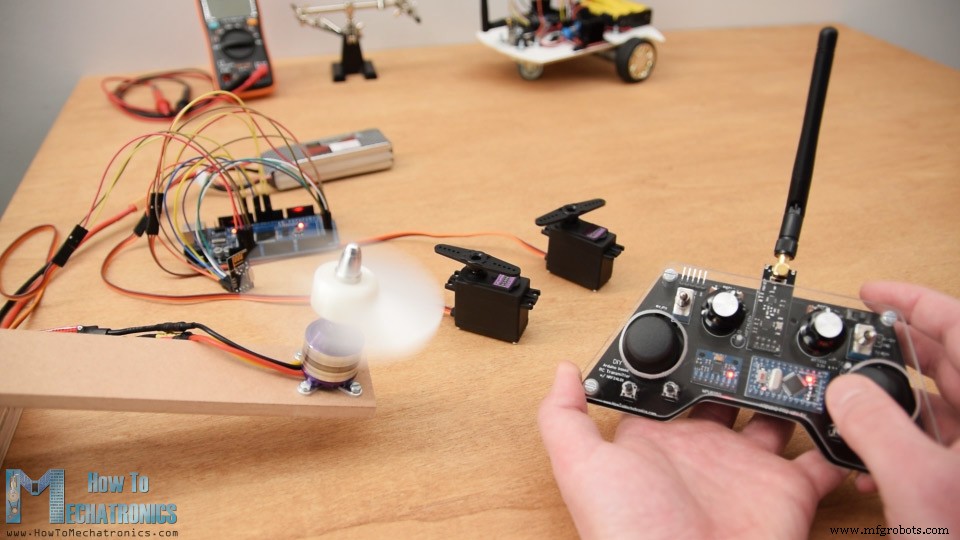
일반적으로 이러한 장치의 경우 서보 또는 브러시리스 모터를 제어해야 합니다. 따라서 송신기에서 데이터를 수신한 후 서보를 제어하기 위해 Arduino Servo 라이브러리를 사용하고 0도에서 180도 사이의 값을 사용하기만 하면 됩니다. ESC를 사용하여 브러시리스 모터를 제어하기 위해 ESC를 제어하는 데 사용되는 50Hz PWM 신호를 생성하기 위해 서보 라이브러리를 다시 사용할 수 있습니다. 듀티 사이클을 1000에서 2000마이크로초로 변경하여 모터의 RPM을 0에서 최대로 제어합니다. 그러나 다음 튜토리얼에서 ESC를 사용하여 브러시리스 모터를 제어하는 방법에 대해 자세히 설명합니다.
Please note that we actually cannot bind the standard RC receiver system with this NRF24L01 2.4GHz system. Instead, we need to modify or create our own receiver consisting of an Arduino and NRF24L01 Module. From there we can than generate the appropriate PWM or PPM signals for controlling the RC device.
/*
    DIY Arduino based RC Transmitter Project
   == Receiver Code - ESC and Servo Control ==

  by Dejan Nedelkovski, www.HowToMechatronics.com
  Library: TMRh20/RF24, https://github.com/tmrh20/RF24/
*/
#include <SPI.h>
#include <nRF24L01.h>
#include <RF24.h>
#include <Servo.h>

RF24 radio(10, 9);   // nRF24L01 (CE, CSN)
const byte address[6] = "00001";

unsigned long lastReceiveTime = 0;
unsigned long currentTime = 0;

Servo esc;  // create servo object to control the ESC
Servo servo1;
Servo servo2;
int escValue, servo1Value, servo2Value;

// Max size of this struct is 32 bytes - NRF24L01 buffer limit
struct Data_Package {
  byte j1PotX;
  byte j1PotY;
  byte j1Button;
  byte j2PotX;
  byte j2PotY;
  byte j2Button;
  byte pot1;
  byte pot2;
  byte tSwitch1;
  byte tSwitch2;
  byte button1;
  byte button2;
  byte button3;
  byte button4;
};

Data_Package data; //Create a variable with the above structure

void setup() {
  Serial.begin(9600);
  radio.begin();
  radio.openReadingPipe(0, address);
  radio.setAutoAck(false);
  radio.setDataRate(RF24_250KBPS);
  radio.setPALevel(RF24_PA_LOW);
  radio.startListening(); //  Set the module as receiver
  resetData();
  esc.attach(9);
  servo1.attach(3);
  servo2.attach(4);
}
void loop() {
  // Check whether we keep receving data, or we have a connection between the two modules
  currentTime = millis();
  if ( currentTime - lastReceiveTime > 1000 ) { // If current time is more then 1 second since we have recived the last data, that means we have lost connection
    resetData(); // If connection is lost, reset the data. It prevents unwanted behavior, for example if a drone jas a throttle up, if we lose connection it can keep flying away if we dont reset the function
  }
  // Check whether there is data to be received
  if (radio.available()) {
    radio.read(&data, sizeof(Data_Package)); // Read the whole data and store it into the 'data' structure
    lastReceiveTime = millis(); // At this moment we have received the data
  }
  // Controlling servos
  servo1Value = map(data.j2PotX, 0, 255, 0, 180);
  servo2Value = map(data.j2PotY, 0, 255, 0, 180);
  servo1.write(servo1Value);
  servo2.write(servo2Value);
  // Controlling brushless motor with ESC
  escValue = map(data.pot1, 0, 255, 1000, 2000); // Map the receiving value form 0 to 255 to 0 1000 to 2000, values used for controlling ESCs
  esc.writeMicroseconds(escValue); // Send the PWM control singal to the ESC
}

void resetData() {
  // Reset the values when there is no radio connection - Set initial default values
  data.j1PotX = 127;
  data.j1PotY = 127;
  data.j2PotX = 127;
  data.j2PotY = 127;
  data.j1Button = 1;
  data.j2Button = 1;
  data.pot1 = 1;
  data.pot2 = 1;
  data.tSwitch1 = 1;
  data.tSwitch2 = 1;
  data.button1 = 1;
  data.button2 = 1;
  data.button3 = 1;
  data.button4 = 1;
}Code language: Arduino (arduino)
So that’s it. 이 비디오를 보시고 새로운 것을 배웠기를 바랍니다. 언제든지 아래 댓글 섹션에 질문하고 내 Arduino 프로젝트 컬렉션을 확인하세요.
제조공정
이 Arduino 프로젝트에서는 Arduino를 사용하여 멋진 LED 하트 액자를 만드는 방법을 보여 드리겠습니다. 자세한 내용은 다음 동영상을 보거나 아래에 작성된 기사를 읽어보세요. 얼핏 보면 평범한 액자처럼 보이지만 뒷면의 스위치를 누르면 색다른 액자로 변신한다. 이 Arduino 프로젝트를 구축하는 것은 매우 재미있으며 사랑하는 사람을 위한 완벽한 발렌타인, 생일 또는 기념일 선물이 될 수 있습니다. 이제 빌드를 시작해 보겠습니다. 포토 프레임 준비 먼저 간단한 18 x 13cm 사진 프레임과 LED를 삽입하기 위
요즘에는 Arduin으로 무엇이든 컴퓨터로 바꿀 수 있습니다. 키패드가 있는 LED 또는 LCD가 보이면 누군가 그 장치 안에 랩톱을 넣었을 것입니다. 이들 중 일부는 마이크로컨트롤러라고 하는 6개, 7개 또는 그 이상의 소형 컴퓨터를 포함합니다. 그 중 Arduino가 가장 인기가 있습니다. 컴퓨터가 내장된 전자 장치를 만들 계획이라면 전자 장치가 무엇이며 어떻게 작동하는지 이해해야 합니다. 그래야만 PCB 상점에서 몇 가지 키트를 구입하고 프로젝트를 시작할 수 있습니다. Arduino란 무엇입니까? 이러한 소형 마이크로컨