

제조공정

산업 제조
연주강의 함유물 및 검출
철강의 연속 주조는 에너지 절약, 높은 수율, 작업 유연성 및 주조 제품의 경쟁력 있는 품질이라는 고유한 이점으로 인해 전 세계적으로 철강 생산에 중요한 공정입니다. 연속주조가 철강 생산의 주요 경로로 확립됨에 따라 연속주조 기술을 통한 철강 생산의 품질 향상 및 원가 절감 측면에 더욱 중점을 두고 있습니다. 오늘날 가장 엄격한 품질 요구 사항 중 하나는 강철의 청결도입니다. 높은 강철 청정도는 연속 주조 공정 중 비금속 개재물 또는 단순히 개재물에 대한 엄격한 제어를 요구합니다. 최종 제품에 남아 있는 개재물은 강철 속성을 손상시키고 품질을 저하시킬 수 있습니다.
연속주조의 금형 내 개재물 제거는 액강이 고형화되어 개재물이 떠오를 기회가 적기 때문에 어렵습니다. 개재물의 제거와 강재의 개재물의 최종 분포는 개재물의 성질, 액강내의 개재물의 수송, 개재물과 응고 쉘의 상호작용에 크게 좌우된다. 따라서 개재물의 포획과 최종 제품의 최종 분포에 대한 이해는 철강 제품의 청결도와 품질을 제어하는 데 중요합니다.
열연 및/또는 냉간 압연 강철의 표면 품질 문제는 강철 품질 및 가격과 직접적인 관련이 있기 때문에 항상 중요한 문제 중 하나입니다. 압연강재의 표면 품질은 연속 주조 및 재가열 공정의 운전에 의해서도 영향을 받으며, 개재물은 압연강재의 표면 균열을 발생시키는 주요 원인 중 하나이기 때문입니다. 열역학 계산을 기반으로 Inclusion 조성과 형태를 수정하여 강철 표면 품질을 향상시키려는 시도가 있습니다. 그러나 이러한 시도는 표면 품질 문제를 완전히 해결하기에는 아직 충분하지 않은 것 같습니다.
철강 내 개재물의 평가는 매우 흥미롭고 (i) 개재물의 총량, 형태, 크기 분포 및 공간적 분포를 탐색하고 (ii) 이들의 화학적 조성을 식별하는 것을 포함합니다.
고품질 철강 제품에 대한 계속 증가하는 요구로 인해 제강 직원은 철강 청결 요구 사항을 점점 더 인식하게 되었습니다. 개재물은 과도한 수리 또는 거부로 이어질 수 있는 주강의 중요한 문제입니다. 압연 강재 제품의 여러 결함은 개재물과 관련될 수 있습니다. 강재의 기계적 거동은 응력 상승제로 작용하는 개재물 및 침전물의 부피 분율, 크기, 분포, 조성 및 형태에 의해 크게 제어됩니다. 큰 거대 개재물이 기계적 특성에 가장 해롭기 때문에 개재물 크기 분포가 특히 중요합니다. 때때로 치명적인 결함은 완전한 강철 열에 단 하나의 큰 개재물에 의해 발생합니다. 큰 내포물이 작은 내포물의 수보다 훨씬 많지만 전체 부피 비율은 클 수 있습니다.
연성은 산화물 또는 황화물 개재물의 양을 증가시키면 눈에 띄게 감소합니다. 또한 고강도 저연성 합금강에 개재물이 존재하면 파괴 인성이 감소합니다. 크리프, 충격 및 피로 시험과 같이 느리거나 빠르거나 주기적 변형률을 반영하는 시험에서 개재물로부터 유사한 특성 저하가 관찰됩니다. 또한, 개재물은 공극을 유발하여 균열을 유발할 수 있습니다. 외인성 내포물이 크면 표면 불량, 광택 불량, 부식 저항성 감소, 예외적인 경우 슬래그 라인 및 라미네이션 등의 문제가 발생할 수 있습니다.
내포물은 또한 '수소 유도 균열'(HIC)에 대한 저항을 낮춥니다. 강철에서 피로 문제의 대부분의 원인은 단단하고 부서지기 쉬운 산화물, 특히 크기가 30마이크로미터 이상인 큰 알루미나(Al2O3) 입자입니다. 개재물의 응고 형태는 주강에서 중요하지만, 단강 제품의 개재물의 형태는 철강 가공 중 기계적 거동, 즉 강 기지에 대해 '경질'인지 또는 '연질'인지에 의해 크게 제어됩니다. 압연 중 변형이 있는 다양한 유형의 개재물의 거동이 그림 1에 개략적으로 표시됩니다.
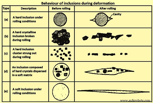
그림 1 변형 중 Inclusion 거동
그림 1의 유형 (b) 및 (c)인 '스트링거' 형성은 기계적 특성의 방향성을 증가시켜 특히 인성과 연성에 부정적인 영향을 미칩니다. 특히 평판 압연 제품의 두께 방향 특성에서 인성 및 연성에 대한 최악의 개재물은 그림 1의 (d)와 같이 매트릭스와 함께 변형되는 개재물입니다. 이러한 문제를 피하기 위해 유해한 개재물의 크기와 빈도는 다음과 같아야 합니다. 신중하게 통제됩니다. 특히 임계 크기 이상의 주강에는 개재물이 없어야 합니다.
개재물의 특성화는 깨끗한 강철을 보장하는 가장 중요한 측면 중 하나입니다. 개재물은 강재의 연마성, 연성 및 피로 강도와 같은 특성에 심각한 영향을 미치는 강재에 존재하는 결함 유형입니다. 따라서 고기능강 생산을 위해서는 개재물 관리가 필요하다. 1차 개재물은 국자에서 강철 처리 중에 형성됩니다. 이들 대부분은 레이들 슬래그 또는 라이닝으로 제거됩니다. 그러나 나머지 Inclusion은 여전히 연속적인 공정 단계를 거쳐 제거되어야 하며 주조 및 응고 과정에서 추가로 새로운 Inclusion이 형성됩니다.
크기가 증가함에 따라 내포물의 수가 감소하기 때문에 크기 간격이 다르면 문제가 발생합니다. 연마성과 관련하여, 다수의 작은 개재물이 단순히 더 자주 발생한다는 점에서 크고 동시에 희귀한 개재물보다 더 유해합니다. 반면에, 낮은 응력 수준에서는 철강 제품의 수명 내에 파손으로 이어질 수 있는 임계 균열이 매우 큰 개재물에서 성장할 가능성이 가장 높습니다. 이러한 내포물은 드물고 발생 밀도를 정확하게 추정하기 어렵습니다. 중간 피로 응력 수준에서 중간 크기의 개재물은 균열 시작점으로서 표면 결함과 경쟁합니다.
강철의 내포물은 내인성(원주민) 또는 외인성으로 형성될 수 있습니다. 내인성 개재물은 강철 내의 합금 원소가 용존 가스(예:산소)와 반응하여 주강에 고체 개재물을 형성한 결과입니다. 포함은 탈산, 재산화 또는 고체 상태에서 감소된 기체 종 용해도로부터 응고 중에 형성될 수 있습니다. 외인성 내포물은 슬래그 비말동반 또는 내화 손상과 같은 액체강 외부의 출처에서 발생합니다.
내인성 포함
내인성 개재물은 강의 냉각 및 응고 중에 탈산 생성물 또는 석출된 개재물입니다.
탈산 제품 – 저탄소 알루미늄 킬드강(LCAK)의 알루미나 개재물과 규소 킬드강의 실리카(SiO2) 개재물은 용존 산소와 첨가된 알루미늄 및 규소 탈산소제의 반응에 의해 생성되는 대표적인 탈산 개재물입니다. 알루미나 개재물은 높은 산소 환경에서 형성될 때 수지상입니다. 탈산 또는 재산화로 인한 클러스터형 알루미나 개재물은 알루미늄 킬드강의 전형입니다. 알루미나 개재물은 높은 계면 에너지로 인해 충돌 및 응집을 통해 3차원 클러스터를 쉽게 형성합니다. 클러스터의 개별 내포물은 직경이 1마이크로미터에서 5마이크로미터일 수 있습니다. 다른 입자와 충돌, 분해 또는 응집되기 전에 꽃판 모양 또는 (응집된) 다면체 내포물이 될 수 있습니다. 또는 산호와 같은 알루미나 내포물은 원래 수지상 또는 클러스터된 알루미나 내포물의 '오스트발트 숙성(Ostwald-ripening)'의 결과로 믿어집니다. 실리카 개재물은 액체 강철에서 액체 또는 유리 상태로 있기 때문에 일반적으로 구형입니다. 실리카는 덩어리로 뭉칠 수도 있습니다.
침전된 내포물 – 이러한 개재물은 강의 냉각 및 응고 중에 형성됩니다. 냉각하는 동안 액체의 용존 산소/질소/황 농도는 높아지지만 해당 요소의 용해도는 감소합니다. 따라서 알루미나, 실리카, 질화알루미늄(AlN) 및 황화물 침전물과 같은 개재물이 생성됩니다. 황화물은 응고 중에 수지상 사이에서 형성되고 액체강에 이미 존재하는 산화물에서 자주 핵을 형성합니다. 이러한 내포물은 일반적으로 작습니다(크기가 10마이크로미터 미만).
외인성 내포물
외인성 개재물은 주로 부수적인 화학적(재산화) 및 주변과 액체강의 기계적 상호작용(슬래그 비말동반 및 내화 라이닝의 침식)으로 인해 발생합니다. 가공 시 채터링이 발생하여 가공부 표면의 움푹 들어간 곳과 가우징, 잦은 파손, 과도한 공구 마모를 유발합니다.
외인성 내포물은 항상 관행과 관련되어 있으며 그 크기와 화학적 조성으로 인해 출처가 확인되는 경우가 많으며 출처는 주로 재산화, 슬래그 비말동반, 라이닝 침식 및 화학 반응입니다. 이러한 내포물에는 다음과 같은 특징이 있습니다.
큰 크기 – 내화 침식으로 인한 외인성 개재물은 일반적으로 슬래그 연행으로 인한 개재물보다 큽니다.
화합물 구성/다상 특성 – 외인성 개재물은 (i) 액강과 실리카의 반응에 의해 슬래그 내 FeO, MnO, 생성된 알루미나 개재물이 표면에 머무를 수 있는 내화성 (ii) 외인성 개재물이 이동함에 따라 발생하는 현상 , 크기가 크기 때문에 표면에 알루미나와 같은 탈산 개재물을 가둘 수 있습니다. (iii) 외인성 개재물은 액체 강철에서 운동하는 동안 새로운 개재물을 석출하기 위한 이종 핵 부위로 작용합니다. (iv) 슬래그 또는 재산화 개재물은 라이닝 내화물과 반응하거나 추가 재료를 액체 강으로 밀어냅니다.
모양 – 외인성 개재물은 슬래그 비말동반 또는 탈산 생성물 실리카로 인해 구형이 아닌 경우 일반적으로 불규칙한 모양을 갖습니다. 구형 외인성 개재물은 일반적으로 크고(50마이크로미터 이상) 대부분 다상이지만 구형 탈산 개재물은 일반적으로 작고 단상입니다.
수량 – 외인성 내포물은 작은 내포물에 비해 수가 적습니다.
배포 – 외인성 개재물은 강에 산발적으로 분포하며 작은 개재물처럼 잘 분산되지 않는다. 그것들은 일반적으로 가득 차고 응고되는 동안 강철에 갇히기 때문에 그들의 발생은 우발적이고 산발적입니다. 다른 한편으로, 그것들은 쉽게 뜨기 때문에 가장 빠르게 응고되는 강철 부분의 영역이나 부상에 의한 탈출이 어떤 식으로든 방해를 받는 영역에만 집중됩니다. 따라서 이러한 내포물은 표면 근처에서 자주 발견됩니다.
철강 특성에 미치는 영향 – 외인성 개재물은 크기가 크기 때문에 작은 개재물보다 강재 특성에 더 해롭다.
외인성 내포물의 원인을 무시하는 한 가지 문제는 왜 그러한 큰 내포물이 일단 강철에 있으면 빠르게 뜨지 않는다는 것입니다. 가능한 이유는 (i) 철강 제조, 이송 또는 야금 용기의 침식 중 늦은 형성으로 인해 주조기 금형에 들어가기 전에 상승할 시간이 충분하지 않고, (ii) 충분한 과열도 부족, (iii) 응고 중 유체 흐름이 유도될 수 있습니다. 몰드 슬래그 포획, 또는 (iv) 부유 개재물이 슬래그에 완전히 들어가기 전에 재연행
재산화로 인한 외인성 내포물 – 재산화로 인한 큰 거대 내포물의 가장 흔한 형태는 강철에서 발견되는 알루미나 클러스터입니다. 공기는 가장 흔한 재산화 원인으로, (i) 강한 난류로 인해 주입 시작 시 턴디쉬의 액강이 상단 표면의 공기와 혼합되고 흐르는 액체 표면의 산화막이 접힙니다. 산화물 입자의 약한 평면을 형성하는 액체 속으로 공기가 흡입되고, 레이들과 턴디쉬 사이, 턴디쉬와 몰드 사이의 접합부에서 공기가 액강으로 흡입되며, (iii) 공기가 강철로 침투합니다. 붓는 동안 국자, 턴디쉬 및 몰드에 있는 강철의 상단 표면.
이러한 종류의 재산화 동안, 알루미늄, 칼슘, 규소 등과 같은 탈산 원소가 우선적으로 산화되고 이들의 생성물은 일반적으로 탈산 개재물보다 1~2배 큰 개재물로 발전합니다. 이러한 종류의 재산화를 방지하기 위한 해결책은 주조 과정에서 공기가 노출되는 것을 제한하는 것입니다. 이것은 (i) 레이들과 턴디쉬 사이, 그리고 턴디쉬와 몰드 사이의 연결부 주위에 강철 링 매니폴드 또는 다공성 내화 링을 사용하여 불활성 가스 커튼으로 가리고, (ii) 일부 아르곤 가스를 내부로 퍼지하여 수행할 수 있습니다. 붓기 전 tundish, 붓는 동안 tundish 표면으로, (iii) 눈 형성을 피하기 위해 국자에서 아르곤 가스 주입을 제어함으로써.
또 다른 재산화 소스는 슬래그와 내화 내화물에 있습니다. 이 재산화 메커니즘에 의해 강철 내의 개재물은 SiO2 / FeO / MnO + [Al] =[Si] / [Fe] / [Mn] + Al2O3 반응을 통해 슬래그 또는 라이닝 계면 근처에서 성장합니다. 이것은 다양한 조성을 가진 더 큰 알루미나 개재물을 초래합니다. 이 현상은 다른 방식으로 외인성 개재물에 추가로 영향을 미칩니다. 즉 (i) 이 반응은 라이닝의 표면을 부식시키고 고르지 않게 할 수 있으며, 이는 라이닝 벽 근처의 유체 흐름 패턴을 변경하고 라이닝의 더 가속화된 분해를 유도할 수 있습니다. (ii) a 파손된 라이닝 또는 동반된 슬래그의 큰 외인성 내포물은 탈산 생성물과 같은 작은 내포물을 포획할 수 있으며 외인성 내포물의 구성을 복잡하게 하는 새로운 침전물에 대한 불균질 핵으로 작용할 수도 있습니다.
슬래그 및 라이닝 내화물의 재산화를 방지하기 위해서는 SiO2, FeO, MnO 함량을 낮게 유지하는 것이 매우 중요합니다. 유리 실리카 함량이 낮은 고 알루미나 또는 지르코니아 벽돌이 사용하기에 더 적합하다고 보고되었습니다.
슬래그 유입으로 인한 외인성 내포물 – 모든 제강 작업 또는 액강 이송에는 특히 용기 간 이송 중에 슬래그와 금속의 난류 혼합이 포함됩니다. 이것은 강철에 부유하는 슬래그 입자를 생성합니다. 크기가 10마이크로미터에서 300마이크로미터인 슬래그 개재물은 다량의 CaO(석회) 또는 MgO(마그네시아)를 포함하며 일반적으로 액강 온도에서 액체이므로 모양이 구형입니다. 'H'자 모양의 턴디쉬를 사용하여 2개의 국자를 통해 붓는 것은 국자 교체 기간 동안 슬래그 혼입을 감소시킵니다. 연속 주조 공정 동안 액강으로의 슬래그 비말동반에 영향을 미치는 원인은 (i) 특히 개방 주입을 위해 래들에서 턴디시로, 턴디시에서 주형으로의 이송 작업 중 액강의 상부 표면에서 와류가 낮은 수준에서 발생합니다. 와류가 시작되기 전에 주입 차단, (ii) 특히 임계 가스 유속 이상의 가스 교반 시 상단 표면의 유화 및 슬래그 비말 동반, (iii) 메니스커스의 난류 금형 내, (iv) 계면 장력 및 슬래그 점도와 같은 슬래그 특성
예를 들어, 금형 분말은 (i) 메니스커스의 난류(그림 2A), (ii) 소용돌이(그림 2C), (iii) 강철에서 슬래그로 이동하는 기포에 의해 유도된 유화로 인해 액체 강철에 갇힐 수 있습니다. [그림 2B 및 2D), (iv) 압력차로 인한 노즐 벽을 따라 흡입(2E), (v) 표면에서 슬래그를 전단하는 고속 흐름(2A), (vi) 수위 변동(그림 2B) .
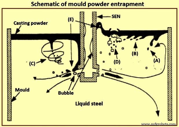
그림 2 도식적인 금형 분말 포획
강철과 액체 주조 분말 사이의 계면 장력은 강철 메니스커스의 높이와 플럭스 비말동반의 용이성을 결정합니다. 특히 순수 철과 접촉하는 석회-실리카-알루미나 슬래그에 대해 미터당 1.4뉴턴(N/m)의 계면 장력은 약 8mm의 메니스커스 높이를 생성합니다. 계면 장력은 황과 같은 표면 활성 종 또는 슬래그의 산화철에 의한 강철의 알루미늄 산화와 같은 계면 교환 반응에 의해 낮은 값으로 감소합니다. 화학 반응과 관련된 매우 낮은 계면 장력은 마랑고니 효과를 통해 계면에서 자발적인 난류를 제공할 수 있습니다. 이러한 난기류는 계면에서 유제를 생성하여 강철에 바람직하지 않은 슬래그 비드를 생성할 수 있습니다.
내화 라이닝의 침식/부식으로 인한 외인성 개재물 – 잘 블록 모래, 느슨한 흙, 부서진 내화 벽돌 및 세라믹 라이닝 입자를 포함하는 내화물의 침식은 일반적으로 단단하고 래들 및 턴디쉬 자체의 재료와 관련된 큰 외생 개재물의 매우 흔한 원인입니다. 이들은 일반적으로 크고 불규칙한 모양의 물질입니다. 외인성 내포물은 알루미나, 의 불균질한 핵 생성을 위한 사이트로 작용할 수 있습니다. 또는 다른 토착 내포물과 합산합니다. 내화 침식 제품 또는 기계적으로 도입된 개재물의 발생은 매우 깨끗한 강철의 품질을 완전히 손상시킬 수 있습니다.
침식 과정을 조사하기 위한 일부 연구에서는 1,550℃ ~ 1,600℃에서 액강으로 '유리 내화물'과 '벽돌 표면의 반응층'이 형성된다는 보고가 있었다. 안감의 표면은 또한 액체 강철로 방출될 수 있습니다.
라이닝 침식은 일반적으로 난류 영역에서 특히 재산화, 높은 주입 온도 및 화학 반응과 결합될 때 발생합니다. 라이닝 침식에 큰 영향을 미치는 매개변수는 아래에 설명되어 있습니다.
일부 강철 등급은 부식성이 매우 높으며(예:망간이 높고 용해성 산소 함량이 높은 등급) 라이닝 벽돌을 공격합니다.
액체강에 용해된 알루미늄이 라이닝 내화물의 실리카를 감소시키는 것과 같은 재산화 반응은 반응성이 매우 높고 라이닝 재료를 적시는 산화철 기반 개재물을 생성하여 높은 유체 난류 영역에서 라이닝 내화물의 침식을 초래합니다.
벽돌의 구성과 품질은 강철의 품질에 상당한 영향을 미칩니다. 한 공장에서는 세 가지 유형의 재료(고알루미나, Al2O3-SiC-C 및 MgO-C 마모율이 각각 1mm/열, 0.34mm/열, 0.16mm/열)를 채택했습니다. 내화물은 침식성 턴디쉬 플럭스와 슬래그에 의해 손상되기 쉬운 슬래그 라인으로 MgO-C 벽돌이 셋 중 가장 높은 내구성을 보인다. 산화망간은 내화물의 일부를 포함하는 실리카를 우선적으로 공격합니다. 고순도 알루미나 및 지르코니아 입자는 산화망간 공격을 견딜 수 있습니다.
고망간강으로부터의 빠른 내화 침식은 (i) 초고순도 알루미나 또는 지르코니아 내화물의 사용, (ii) 알루미늄 또는 칼슘과 같은 강력한 탈산소제로 강철을 완전히 소멸시켜 산소를 최소화하고, 공기 흡수를 방지함으로써 억제될 수 있습니다. 실리카 기반 턴디쉬 라이닝은 마그네시아 기반 스프레이 라이닝보다 나쁩니다. 고 알루미나 내화물이 가장 유망한 것으로 제안되고 있습니다. 산화칼슘을 노즐 내화물에 통합하면 계면으로의 CaO 확산이 충분히 빠르고 노즐 침식이 문제가 되지 않는 한 벽에서 알루미나 개재물을 액화하여 도움이 될 수 있습니다. 노즐 부식은 노즐 내화 성분을 제어하거나(예:나트륨, 칼륨 및 규소 불순물 방지) 노즐 벽을 순수한 알루미나, 질화붕소 또는 기타 저항성 재료로 코팅하여 방지할 수 있습니다. 슈라우드 벽 표면의 내화물은 개재물 및 막힘을 생성하는 강철과의 반응을 최소화하도록 선택해야 합니다.
액체강의 과도한 속도는 입구 영역과 같은 턴디쉬의 벽을 따라 라이닝 침식에 영향을 줍니다. 패드는 턴디쉬 바닥의 침식을 방지하고 흐름 패턴을 제어하는 데 사용할 수 있습니다. 초당 1미터 이상의 액체 강철 속도는 침식과 관련하여 위험하다고 제안되었습니다.
과도한 접촉 또는 충전 시간 및 고온은 침식 문제를 악화시킵니다. 레이들에 오래 머무르는 동안 더 큰 개재물이 레이들 슬래그로 떠오를 수 있습니다. 그러나 강철이 레이들 라이닝과 접촉하는 시간이 길수록 레이들 침식 제품의 경향이 커집니다. 솔루션은 주어진 강종에 대해 매우 안정적인 내화물 개발, 고유동 영역을 위한 고밀도 내마모성 내화물 인서트 개발 및 재산화 방지를 기반으로 합니다.
화학 반응으로 인한 외인성 내포물 – 화학 반응은 칼슘 처리가 부적절하게 수행될 때 개재물 변형으로 인해 산화물을 생성합니다. 이러한 내포물의 출처를 식별하는 것이 항상 쉬운 것은 아닙니다. 예를 들어, 산화칼슘을 함유한 내포물은 동반 슬래그에서 비롯될 수도 있습니다.
포함 응집 및 막힘 – 고형 개재물의 응집은 내화물 및 기포 표면을 포함하여 표면 장력 효과에 의해 도움을 받는 모든 표면에서 발생할 수 있습니다. 액강(134도 ~ 146도)에서 알루미나의 높은 접촉각은 강과의 접촉을 최소화하기 위해 개재물이 내화물에 스스로 부착되도록 합니다. 1,530℃의 높은 온도는 알루미나의 소결을 가능하게 합니다. 접촉각이 크고 개재물의 크기가 클수록 개재물의 응집이 유리합니다. 충돌 및 응집으로 인해 강철의 개재물은 시간과 온도가 증가함에 따라 성장하는 경향이 있습니다. 잉곳의 충돌, 덩어리 및 응고에 의한 개재물 성장은 다양한 연구의 주제였으며, 여기서 탈산소제 첨가에서 시작하는 개재물 핵 생성 및 충돌 및 확산에 의한 나노 크기에서 마이크로 크기로의 성장에 대한 수치 시뮬레이션이 보고되었습니다.
클러스터로 알루미나 소결의 기본 사항은 추가 조사가 필요하지만 일부 연구에서는 클러스터 형태(특징)를 설명하기 위해 프랙탈 이론을 사용했습니다. 내화물 표면의 개재물 덩어리의 가장 명백한 예는 액강의 연속 주조 중 노즐 막힘입니다.
개재물에 대한 유체 흐름 및 응고의 영향 – 강의 연속주조에서 개재물 분포는 액상 강의 유체 흐름, 열 전달 및 응고에 영향을 받습니다. 개재물 포획에 대한 인기 있는 지표는 응고 정면의 임계 진행 속도이며, 이는 개재물 형상, 밀도, 표면 에너지, 열전도도, 냉각 속도(응고 속도) 및 응고 전선의 돌출 조건과 같은 여러 매개변수의 영향을 받습니다. 포획은 항력 및 계면력(Van der Waals force)에 의해 제어되는 것으로 보고되었습니다. 응고 속도가 빠를수록 갇힐 확률이 높다고 제안되었습니다. 갇힐 확률은 응고 시간이 증가하고 분리가 적고 응고 전면의 돌출부가 작아짐에 따라 감소합니다. 덴드라이트 암 간격은 개재물의 포획에 큰 영향을 미치며 미는 현상, 함몰과 관련이 있습니다. 또는 함정.
연속 주조 작업, 개재물 및 깨끗한 강철
연속 주조 작업은 강철 청결도를 제어합니다. 개재물 제거에 대한 체계적인 연구에 따르면 래들 처리는 개재물을 약 65%에서 75%까지 낮추고 턴디쉬는 개재물을 약 20%에서 25%까지 제거하지만 때로는 재산화가 발생하며 금형은 약 5%까지 개재물을 제거합니다. 10% . Tundish 작업은 철강 청결도에 큰 영향을 미칩니다. 강철 청결도에 영향을 미치는 턴디시 작업의 중요한 요소는 턴디시 깊이 및 용량, 주조 전이, 턴디시 라이닝 내화물, 턴디시 플럭스, 아르곤 가스 교반 및 턴디시 흐름 제어입니다.
상부 슬래그 – 레이들 및 턴디쉬의 상부 슬래그는 (i) 열적으로(과도한 열 손실을 방지하기 위해) 화학적으로(공기 유입 및 재산화를 방지하기 위해) 액체강의 절연 및 (ii) 개재물의 흡수와 같은 여러 기능을 제공합니다. 추가 철강 정제를 제공합니다. 일반적인 턴디쉬 플럭스는 구운 왕겨이며, 이는 저렴하고 우수한 단열재이며 크러스트 없이 우수한 피복을 제공합니다. 그러나 왕겨는 실리카(약 80% SiO2)가 높기 때문에 환원되어 내포물의 원인이 될 수 있습니다. 또한 먼지가 많고 탄소 함량이 높기 때문에(C 약 10%) 초저탄소강을 오염시킬 수 있습니다.
기본 플럭스(CaO-Al2O3-SiO2 기반, 실리카 10% 미만)는 이론적으로 LCAK 강을 정련하는 동안 왕겨보다 훨씬 우수하며 턴디쉬의 낮은 산소와 상관관계가 있습니다. 예를 들어, 한 연구에서 총 산소는 플럭스의 염기도가 0.83에서 11로 증가하면서 25ppm(백만분율) 및 50ppm 범위에서 19ppm 및 35ppm 범위로 감소했습니다. 철강 공장, 기본 플럭스 사용, 금형 내 총 산소가 더 낮은 것으로보고되었으며 철강 제품 결함이 감소했습니다. 그러나 기본 플럭스는 더 빠른 용융 속도와 높은 결정화 온도로 인해 표면에 크러스트를 쉽게 형성하기 때문에 비효율적일 가능성이 더 큽니다. 이 크러스트는 티밍 동안 레이들 슈라우드 주변에 슬래그가 없는 열린 눈의 진화를 초래하며, 이는 재산화를 위한 과도한 영역을 제공할 뿐만 아니라 작업 플랫폼의 작업자에게 상당한 복사 열 손실 및 불편함을 허용합니다. 또한 기본 플럭스는 일반적으로 점도가 더 낮습니다. 따라서 그들은 더 쉽게 동반됩니다. 이러한 문제를 피하기 위해 한 제철소는 2층 플럭스를 사용했습니다. 바닥에는 개재물을 흡수하기 위해 저융점 기본 플럭스가 있고 절연을 제공하기 위해 왕겨 기반 플럭스의 최상층은 있습니다. 이로써 총 산소량이 22.5ppm에서 16.5ppm으로 낮아졌습니다.
턴디쉬 깊이, 용량 및 흐름 제어 장치 – 턴디쉬 흐름 패턴은 액강 체류 시간을 늘리고 '단락'을 방지하며 개재물 제거를 촉진하도록 설계되어야 합니다. Tundish 흐름은 형상, 레벨, 입구(슈라우드) 설계 및 충격 패드, 둑, 댐, 배플 및 필터와 같은 흐름 제어 장치에 의해 제어됩니다. 대용량의 Deep tundish는 액체강 및 입자의 체류 시간을 증가시켜 개재물 제거를 촉진합니다. 깊은 턴디쉬는 또한 와류 형성을 억제하여 슬래그 비말동반이 문제가 되기 전에 국자 전환에 더 많은 시간을 허용합니다. LCAK 강재의 턴디쉬 크기는 지난 20년 동안 전 세계적으로 점진적으로 증가했으며 일반적으로 슬래브 연속 주조기의 경우 깊이가 약 1.8미터인 60톤에서 80톤에 이릅니다.
적절하게 정렬되고 둑과 댐과 함께라면, 붓는 패드는 특히 레이들을 교환하는 동안 강철 청결도를 향상시킬 수 있습니다. 예를 들어, 철강 공장 중 하나에 붓는 패드를 추가하면 래들 전환 중 알루미나가 48ppm에서 15ppm으로 감소했습니다. 다른 철강 공장에서는 총 산소량이 26ppm(돔형 패드 포함)에서 22ppm(허브 캡 패드 포함)으로 감소했습니다. 또 다른 철강 공장에서는 댐에 77개의 구멍을 뚫어 부분 필터 역할을 하여 철강 청정도를 향상시켰습니다. 다른 한 철강 공장에서는 초기 턴디쉬 덮개와 결합된 배플을 구성하는 유사한 기술이 정상 상태 주조 동안 턴디쉬의 평균 총 산소를 39 +/- 8 ppm에서 24 +/- 5 ppm으로 낮췄습니다.
세라믹 필터와 CaO 필터는 개재물 제거에 매우 효과적입니다. 그러나 막히기 전에 비용과 효과적인 작동 시간으로 인해 일반적으로 사용이 금지됩니다. 턴디쉬 바닥에서 불활성 가스를 주입하면 액강의 혼합이 향상되고 충돌 및 개재물 제거가 촉진됩니다. 한 철강 공장에서 이 기술을 적용하여 총 산소를 턴디쉬에서 16ppm으로 성공적으로 낮췄습니다. 그러나 이 기술의 위험은 턴디시를 빠져나와 스트랜드에 갇힌 내포물이 포함된 기포가 심각한 결함을 유발한다는 것입니다. 턴디쉬에서 강철의 산화물 면적 분율(0.001%)은 이 기술이 없는 것과 비교하여 이 기술로 25% 감소하는 것으로 보고되었습니다.
전송 전환 – 주조 전환은 주조 순서 시작 시, 레이들 교환 및 노즐 교환 중, 주조 종료 시 발생합니다. 이러한 전환은 대부분의 청정도 결함에 대한 책임이 있습니다. 개재물은 전환 중에 자주 생성되고 오랫동안 지속되어 많은 철강을 오염시킬 수 있습니다. 1차 가열 초기의 은색 결함 지수는 1차 가열 중반보다 5배, 연속 가열보다 15배 이상 높은 것으로 밝혀졌다. 이러한 불안정한 주조 기간 동안 슬래그 비말동반 및 공기 흡수가 더 많이 일어나 재산화 문제를 유발합니다. '자체 개방' 국자는 노즐을 랜싱하지 않고도 저절로 열립니다. 랜싱은 슈라우드를 제거해야 하며, 이는 특히 주조의 처음 650mm에서 1,200mm 동안 재산화가 일어날 수 있도록 합니다. 창 열림 열은 자체 열림 열보다 약 10ppm 더 높은 총 산소 수준을 갖습니다. 국자 열림 모래를 조심스럽게 포장하면 국자 자체 열림을 달성하는 데 도움이 됩니다. 국자 모래는 또한 실리카 함량이 높기 때문에 재산화의 원인이 됩니다.
레이들 전환 중 한 가지 개선 사항은 턴디쉬가 채워질 때까지 금형으로의 액체 흐름을 멈추고 스토퍼를 통해 가스를 버블링하여 포함 부유물을 촉진하는 것입니다. 또 다른 개선 사항은 잠긴 덮개가 있는 새 국자를 여는 것입니다. 이 측정을 통해 철강 공장 중 한 곳의 총 산소량이 41 +/- 14ppm에서 31 +/- 16ppm으로 감소했으며 시퀀스 전반에 걸쳐 품질이 더 일관되었습니다.
As an example, at one of the steel plant, total oxygen in tundish during transitions is 50 ppm to 70 ppm, compared with only 25 ppm to 50 ppm at steady state. At other steel plants, the difference is only 3 ppm. One of the steel plants has reported transitions to have total oxygen only 19.2 ppm relative to 16 ppm at steady state while another steel plant has reported total oxygen of 27 +/- 5 ppm during transitions and 24 +/- 5 ppm during steady casting. At one other steel plant, the nitrogen pickup in tundish is 5 ppm to 12 ppm during the start period of the teeming which decreases to 0 ppm to 2 ppm after around 12 minute of teeming (steady casting state).
Near the end of the teeming of a ladle, ladle slag can enter the tundish, due to the vortex formed in the liquid steel near the ladle exit. This phenomenon needs some steel to be kept in the ladle upon closing (e.g. a four ton of ‘heel’). In addition, the tundish depth drops after ladle close, which disrupts normal tundish flow and can produce slag vortexing, slag entrainment, and increased total oxygen in the mould.
Shrouding, argon protection, and sealing – Steel shrouding from ladle to the mould includes ladle slide gate shrouding, ladle collector nozzle, ladle shroud connection, tundish well block, and top plate of the tundish slide gate. Shroud design variations are of great importance in the operations of the tundish-to-mould transfer of liquid steel. Use of an optimized shrouding system greatly lowers reoxidation during transfer operations. For example, use of a ladle shroud has lowered nitrogen pickup from 24 ppm to 3 ppm relative to open pouring at one of the steel plant. In another steel plant, replacing the tundish pour box with a ladle shroud and dams has lowered nitrogen pickup (ladle to tundish) from 7.5 ppm to 4 ppm, and also has lowered slag entrainment during transitions. At one other steel plant, improving the shroud system from ladle to tundish has lowered the nitrogen pickup from 14 ppm to 3 ppm.
Shrouding the ladle to tundish stream at one of the steel plants has lowered the dissolved aluminum loss from 130 ppm to 70 ppm and has lowered the total oxygen increase by 12 ppm. When pouring without shrouds, which is common in billet casting, the turbulence of the casting stream is very important. A smooth stream entrains much less oxygen than a turbulent or ‘ropy’ stream. For the production of a smooth stream between the tundish and the mould in these operations, the metering nozzle edges are to be maintained and high speed flow in the tundish across the nozzles is to be avoided. A protective tundish cover with carefully sealed edges also helps in lowering total oxygen from 41.5 ppm to 38 ppm.
A variety of inert gas shrouding systems is now available. Total oxygen in the cast product (LCAK steel) can be lowered from 48.5 ppm to 28.5 ppm by shrouding between the ladle and the tundish, and to 23 ppm by this shrouding plus argon sealing. It is very important to carefully seal the joints in the shrouds, both to improve cleanliness and to prevent clogging. Improving the bayonet system between the ladle nozzle and ladle shroud, lowers the nitrogen pickup there from 8 ppm to less than 1 ppm. Stiffening the submerged entry nozzle (SEN) holder and increasing its maintenance has lowered the initial nitrogen pickup from 1.8 ppm to 0.3 ppm in one of the steel plants.
Inert gas can protect the steel from air reoxidation in several ways. To combat air entrainment at the beginning of a cast, the tundish can be purged with inert gas (to displace the air) prior to ladle opening, which lowers both the total oxygen and the nitrogen pickup during startup. Argon injection to pressurize the shrouds can help to prevent the liquid steel from air reoxidation through any joints or leaks. Guidelines for minimum argon gas flow to ensure positive pressure inside the nozzle are to be made. In addition, flooding the joints with argon gas ensures that any leaks aspirate inert gas and not air.
Injecting argon into the tundish stopper rod and improved sealing at one steel plant has decreased nitrogen pickup from tundish to cast product from 5 ppm to 1.8 ppm, has lowered total oxygen in the cast product from 31 ppm to 22 ppm, has decreased the size of alumina clusters in the cast product, and has decreased clogging. Elsewhere, argon injection through the stopper rod lowered the number of inclusions detected by the Mannesmann inclusion detection by analysis surfboards (MIDAS) method by 25 % to 80 %. Injection of argon gas purge through upper plate of the sliding gate has lowered the quantity of 50 micrometers to 100 micrometers sized inclusions from 3 per square centimeter to 0.6 per square centimeter, and lowered 100 micrometers to 200 micrometers macro-inclusions from 1.4 per square centimeter to 0.4 per square centimeter.
Clogging and new techniques at SEN – The nozzle is one of the few control parameters which is relatively inexpensive to change, yet has a profound influence on the flow pattern and hence on the quality of the cast product. Nozzle parameters include bore size, port angle and opening size, nozzle wall thickness, port shape (round, square, or oval), number of ports (bifurcated or multiport), nozzle bottom design (well, flat , or sloped), and submergence depth. Both too large and too small submergence depth increases problems with longitudinal cracks and transverse depressions.
One of the studies has found the occurrence of corundum (Al2O3) covering the bore surface of nozzles used to pour aluminum killed steel ingot early in 1949. Another study has found that nozzle blockage occurred with high levels aluminum (0.0036 %) and that nozzle sectioning revealed dendritic growth of alumina from the nozzle wall onto the bore. Yet another study has observed clogs of aluminum, zircon, titanium, and the rare earths.
Nozzle clogs are caused by reoxidation, or by the accumulation of solid oxides or sulphides, such as alumina and calcium sulphide (CaS) in the steel. In addition to interfering with the production process, tundish nozzle / SEN clogging is detrimental to steel cleanliness for several reasons such as (i) dislodged clogs either become trapped in the steel, or they change the flux composition, leading to defects in either case, (ii) clogs change the nozzle flow pattern and jet characteristics leaving the nozzle, which disrupt flow in the mould, leading to slag entrainment and surface defects, and (iii) clogging interferes with mould level control, as the flow control device (stopper rod or slide gate) tries to compensate for the clog.
The cure for the nozzle clog problem includes improving steel cleanliness by improving ladle practices, implementing smooth and non-reacting refractories, and controlling fluid flow though the nozzle for ensuring a smooth flow pattern. Changing from a three-plate slide gate system to a stopper rod system has reduced clogging at one of the steel plant. Several practices can be used to minimize clogging. In addition to taking general measures to minimize inclusions, clogging through refractory erosion can be countered by controlling nozzle refractory composition, (e.g. avoiding sodium, potassium, and silicon impurities), or coating the nozzle walls with pure alumina, boron nitride, or other resistant material. There are several new techniques at SEN which have reported to improve the fluid flow pattern and inclusion removal, such as (i) swirl-nozzle technique, (ii) step nozzle technique, (iii) multi-ports nozzle, and (iv) oval offset bore throttle plate.
Swirl-nozzle technique – A fixed blade placed at the upstream end of the SEN induces a swirl flow in nozzle. Centrifugal force generated by the swirling flow in the nozzle can distribute the liquid steel equally to its two spouts. Since liquid steel stream with centrifugal force has the maximum velocity in the vicinity of the wall inside the nozzle, it tends to flow out of the upper part of the spout. Hence, the velocity distribution which tends to have higher values toward the lower part of the spout with a conventional nozzle can become uniform. It has been reported that by using this swirl nozzle for the continuous casting, the defect ratio of finish products (coils) has decreases to 25 % of the conventional nozzles, and casting speed has riseby 30 %. Its cost is higher only by 20 % than the cost of the conventional and hence it is cheaper than using an ‘electro-magnetic brake’. This swirl flow pattern can also be generated by the ‘electro-magnetic stirring’ at the nozzle, which can also improve the solidification structure of the cast steel as well.
Step nozzle – The flow pattern at out-ports of conventional SEN is uneven or biased because of the sliding gate of SEN. This biased flow pattern (swirl flow at out-ports of SEN) increases the impingement of the jet, and hence worsens inclusion removal to top surface. By using inner annular steps, the biased flow in mould can be weakened. The calculation suggests that the removal fraction of 50 micrometers inclusions to the top surface of the mould is 2 % with the conventional SEN, but increases to 7 % with the use of the stepped SEN.
Oval offset bore throttle plate – In the conventional system, gate throttling results in a highly skewed and biased flow in the tundish-to-mould flow channel both upstream and downstream of the gate. These effects have considerably diminished the offset bore system. The offset gate design extracts the fluid more centrally from the tundish well nozzle. Hence, the system is less sensitive to any build-up on the walls of the well nozzle, which extends the useful life of the tundish well nozzle and hence, allowing longer tundish sequences. In practice, it has also been found that clogging within the plates of the offset bore gate is considerably reduced as compared to the conventional gate.
Multiple out-ports – It is well known that the surface velocity of the mould has a big effect on slag entrainment and top surface fluctuation. Several defects are related to the surface velocity of the mould. Thus decreasing the surface velocity is very important to improve the steel cleanliness. This task can be targeted by using multiple out-ports at SEN. Addition of a bottom hole at SEN lowers the momentum of the side jets so it is possible to get a good steel flow and meniscus condition even under high throughput which is better stabilized.
Mould and operation of continuous casting machine
The continuous casting mould region is the last refining step where inclusions either are safely removed into the top slag layer or they become entrapped into the solidifying shell to form permanent defects in the steel product. Mcpherson has used the words ‘mould metallurgy’ in 1985 to emphasize the importance of the mould to improve steel cleanliness. The mould flow pattern is very important for avoiding defects since it affects particle transport and removal to the top slag or entrapment by the solidifying shell.
Top surface control – Directing too much flow towards the top surface generates surface defects, due to transients, turbulence at the meniscus, and inclusion problems from slag entrainment. However, decreasing surface flows too much can also generate problems. These include surface defects due to the meniscus region becoming too stagnant, and a higher fraction of incoming inclusion particles being sent deep before they can be removed into the slag. Hence, a balance is to be found in order to optimize the flow parameters to avoid defects.
The most obvious source of surface defects is the capture of foreign particles into the solidifying shell at the meniscus. If the steel jet is directed too deep or has too little superheat, then the liquid surface has very little motion and becomes too cold. This can lead to freezing of the steel meniscus, which aggravates the formation of meniscus hooks. This allows inclusions and bubbles to be captured, the latter forming pinholes just beneath the surface of the cast product. As an example, decreasing surface velocity below 0.4 metre/second (m/s) has been measured to increase surface pinhole defects. For avoiding these problems, the flow pattern is to be designed to exceed a critical minimum velocity across the top surface, which is estimated to be around 0.1 m/s to 0.2 m/s.
Slag entrainment is less likely with deeper nozzle submergence and slower casting speed. For avoiding shearing slag in this manner, the surface velocity is to be kept below a critical value. This critical velocity has been measured in water – oil models as a function of viscosity and other parameters. Entrainment is more difficult for shallower slag layers, higher slag viscosity, and higher slag surface tension.
A maximum limit of the argon gas injection flow rate into the nozzle has been reported as a function of the casting speed, beyond which mould slag entrainment takes place. Increasing casting speed tends to increase transient turbulent fluctuations, and worsens the extent of flow pattern asymmetries. This in turn worsens detrimental surface turbulence and level fluctuations. Improving internal cleanliness frequently needs limiting the maximum casting speed, to avoid pencil pipe defects. Lower casting speed and avoiding variations in casting speed both reduce the rate of slivers. More precisely, it is important to lower the liquid mass flow rate in order to control the jet velocity leaving the nozzle.
Fluid flow pattern – The mould flow pattern is controlled by adjustable parameters such as nozzle geometry nozzle submergence depth, argon gas injection rate, and the application of electro-magnetic forces. It also depends on parameters which normally cannot be adjusted to accommodate the flow pattern, such as the position of the flow control device (slide gate or stopper rod), nozzle clogging, casting speed, strand width, and strand thickness. All of these parameters together form a system which is to be designed to produce an optimal flow pattern for a given operation.
Bubbles, which are injected into the nozzle and the mould, have five effects related to the control of tge steel quality. These effects are (i) helping to reduce nozzle clogging, (ii) helping influence and control the flow pattern in the mould, (iii) generating serious top surface fluctuation even emulsification if gas flow rate is too large, (iv) capturing inclusions as they flow in the liquid steel, and (v) bubbles entrapped solid oxide particles captured by solidified shell eventually lead to surface slivers or internal defects.
Normally, low gas flow tends to double-roll flow pattern, while a high argon flow rate induces single-roll flow. This phenomenon has been studied as early as in 1983. For maintaining a stable double roll flow pattern, which is frequently optimal, the argon is to be kept safely below a critical level. Excessive argon injection can generate transient variation of the jets entering the mould, introduce asymmetry in the mould cavity, and increase surface turbulence. Argon gas bubbles can also be trapped in the solidifying steel shell to form blister defects, such as pencil pipe in the finish product.
It has been observed that inclusion entrapment varies from side to side, which suggests a link with the variations in the transient flow structure of the lower recirculation zone, and the asymmetrical flow pattern (Fig 3), which can be induced by nozzle clogging, by turbulence, and by excessive argon gas injection. It is especially important to keep nearly constant the liquid steel level in the mould, powder feeding rate, casting speed, gas injection rate, slide gate opening, and nozzle position (alignment and submergence).
Electro-magnetic forces can be applied to the liquid steel in a number of ways to alter considerably the flow pattern in the strand. It has been reported that electro-magnetic stirring of outer strands can improve the steel cleanliness, lowering total oxygen in the cast product from 30 ppm to 20 ppm. Another example is the electro-magnetic brake (EMBR), which bends the jet and shortens its impingement depth, to lessen the likelihood of capture by the solidified shell deep in the strand.
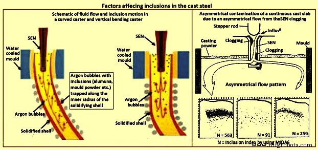
Fig 3 Factors affecting inclusions in cast steel
Casting machine curvature – Continuous casting machines with curved mould are known to entrap more particles than straight (vertical) mould casting machines (Fig 3), since the particles gradually move upwards towards the inside radius while they spiral with the liquid in the lower recirculation zone. Majority of the particles are captured 1 m to 3 m below the meniscus, independent of casting speed, which corresponds to a specific distance through the strand thickness. Frequently, inclusions concentrate at surface and one-eighth to one-fourth of the thickness from the top of the inside radius surface. The vertical bending casting machine has fewer inclusions and pinholes, which are distributed deeper, relative to the curved casting machine. Particle entrapment defects such as pencil pipe can be lessened if at least the top 2.5 m section of the casting machine is straight (vertical).
Inclusions detection methods
The quantity, size distribution, shape and composition of inclusions are required to be measured at all stages of the production of steel. Measurement techniques range from direct methods, which are accurate but costly, to indirect methods, which are fast and inexpensive, but are only reliable as relative indicators. The inclusion detection methods are sometimes divided into two categories namely (i) off-line methods, and (ii) online methods.
Direct methods
There are several direct methods to evaluate steel cleanliness. These methods are described below.
Inclusion evaluation of solid steel sections
Several traditional methods directly evaluate inclusions in a two dimensional section through solidified product samples. The last five of the methods described below add the ability to measure the composition of the inclusions.
Metallographic microscope observation (MMO) – MMO method can only reveal the two-dimensional section of an inclusion though the inclusions are three-dimensional in nature.
Image analysis (IA) – This enhancement to MMO improves on eye evaluation by using high speed computer evaluation of video-scanned microscope images to distinguish dark and light regions based on a grey scale cutoff.
Sulphur print – It is a popular and inexpensive macro-graphic method which distinguishes macro-inclusions and cracks by etching sulphur rich areas. It has the same issues as the other two-dimensional methods.
Scanning electron microscopy (SEM) – This method clearly reveals the three-dimensional morphology and the composition of each inclusion. Composition can also be measured with ‘electron probe micro analyzer’ (EPMA).However, extensive sample preparation is needed to find and expose the inclusion(s).
Optical emission spectrometry with pulse discrimination analysis (OES-PDA) – The optical emission spectrometry (OES) method analyzes elements dissolved in liquid steel. Inclusions cause high intensity spark peaks (relative to the background signal from the dissolved elements), which are counted to give the PDA (pulse discrimination analysis) index.
Laser micro-probe mass spectrometry (LAMMS) – In this method, individual particles are irradiated by a pulsed laser beam, and the lowest laser intensity above a threshold value of ionization is selected for its characteristic spectrum patterns due to their chemical states. Peaks in LAMMS spectra are associated with elements, based on comparison with reference sample results.
X-ray photoelectron spectroscopy (XPS) – This method use x-rays to map the chemical state of individual inclusions which greater than 10 micrometers in size.
Auger electron spectroscopy (AES) – This method use electron beams to map the composition of small areas near the surface of flat samples.
Cathodoluminescence microscope – Under microscope, the steel or lining sample section is stimulated by a cathode-ray (energetic electron-beam), to induce cathodoluminescence (CL). The colour of CL depends on the metal ions type, electric field, and stress, allowing inclusions to be detected.
Inclusion evaluation three-dimensional steel matrix
Several methods directly measure inclusions in the three-dimensional steel matrix. The first four of these scan through the sample with ultrasound or x-rays. The last four of these volumetric methods first separate the inclusions from the steel.
Conventional ultrasonic scanning (CUS ) – In this method, the transducer (typically a piezoelectric) emits a sound pressure wave which is transferred into the sample with the aid of a coupling gel. The sound waves propagate through the sample, reflect off at the back wall and return to the transducer. The magnitude of the initial input pulse and the reflected signals are compared on an oscilloscope to indicate the internal quality of the sample. Obstructing objects in the path of the sound scatters the wave energy. This non-destructive method detects and counts inclusions larger than 20 micrometers in the solidified steel samples.
Mannesmann inclusion detection by analysis surfboards (MIDAS) – In MIDAS method the steel samples are first rolled to remove the porosity and then ultrasonically scanned to detect both the solid inclusions and compound solid inclusions / gas pores. This method has been now renamed as the ‘liquid sampling hot processing’ (LSHP) method.
Scanning acoustic Microscope (SAM) – In this method, a cone-shaped volume of continuous cast product is scanned with a spiraling detector, such as a solid ultrasonic system, which automatically detects inclusions at every location in the area of the sample surface, including from surface to centre-line of the product.
X-ray detection – By this method, inclusions images are detected by their causing variation in the attenuation of x-rays transmitted through the solid steel. An inclusion distribution can be constructed by dividing a sample into several wafers and subjecting each to conventional x-rays to print penetrameter radiograghs for image analysis.
Chemical dissolution (CD) – In the CD method, acid is used to dissolve the steel and partially extract the inclusions. The inclusion morphology and composition can be detected by another method like SEM, or be fully extracted by dissolving the complete steel sample. The three dimensional nature of inclusions can be revealed by this method. The disadvantage is that the acid dissolves away FeO, MnO, CaO, and MgO in the inclusions. Hence, this method is good to detect only alumina and silica inclusions.
Slime (electrolysis) technique – This method is also called ‘potentiostatic dissolution technique’. A relatively large (200 grams to 2 kilograms) steel sample is dissolved by applying electric current through the steel sample immersed in a ferrous chloride or ferrous sulphate solution. This method is used to reveal the individual, intact inclusions. One disadvantage of this method is the cluster inclusions possibly break into separate particles after extraction from steel.
Electron beam (EB) melting – In this method, a sample of aluminum killed steel is melted by an electron beam under vacuum. Inclusions float to the upper surface and form a raft on top of the liquid sample. The normal EB index is the specific area of the inclusion raft. An enhanced method (EB-EV – ‘extreme value’) has been developed to estimate the inclusion size distribution.
Cold crucible (CC) melting – Inclusions are first concentrated at the surface of the melted sample as in the EB melting. After cooling, the sample surface is then dissolved, and the inclusions are filtered out of the solute. This method improves on EB melting by melting a larger sample and being able to detect silica.
Fractional thermal decomposition (FTD) – When temperature of a steel sample exceeds its melting point, inclusions can be revealed on the surface of the liquid and decomposed. Inclusions of different oxides are selectively reduced at different temperatures, such as alumina based oxides at 1,400 deg C or 1,600 deg C, or refractory inclusions at 1,900 deg C. The total oxygen content is the sum of the oxygen contents measured at each heating step.
Magnetic particle inspection (MPI) – This method also called magnetic leakage field inspection can locate inclusions larger than 30 micro-meters in steel sheet products. The test procedure consists of generating a homogeneous field within the steel sheet which is parallel to the sheet surface. If an inhomogeneity (such as an inclusion or a pore) is present, the difference in magnetic susceptibility forces the magnetic flux field to bend and extend beyond the surface of the sheet. The main disadvantage of this method is poor resolution of inclusions which are close together.
Inclusion size distribution after inclusion extraction
Several methods can find three-dimensional inclusion size distributions after the inclusions are extracted from the steel using a suitable method described earlier.
Coulter counter analysis – in this method, particles which flow into the sensor through its tiny hole are detected because they change the electric conductivity across a gap. The method measures the size distribution of inclusions extracted by slime and suspended in water.
Photo scattering method – Photo-scattering signals of inclusions (which have been extracted from a steel sample using another method such as slime, are analyzed to evaluate the size distribution.
Laser diffraction particle size analyzer (LDPSA) – This laser technique can evaluate the size distribution of inclusions which have been extracted from a steel sample using another method such as slime.
Inclusion evaluation of liquid steel
There are several approaches which can be used to detect the inclusion quantity and the size distribution in the liquid steel.
Ultrasonic techniques for liquid system – This method captures the reflections from ultrasound pulses to detect on-line inclusions in the liquid steel.
Liquid metal cleanliness analyzer (LIMCA) – This on-line sensor uses the principle of the ‘Coulter counter’ to detect inclusions directly in the liquid steel. This method is normally used for aluminum and other metals, and it is still under development for steel.
Confocal scanning laser microscope – This new in-situ method can observe the behaviour of individual inclusions moving on the surface of the liquid steel, including their nucleation, collision, agglomeration, and pushing by interfaces. The detected alumina inclusion clustering process on a liquid surface by this method is shown in Fig 4.
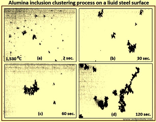
Fig 4 Alumina inclusion clustering process on a liquid steel surface
Electromagnetic visualization (EV) – This Lorentz-force-based detection system is used to accelerate inclusions to the top free surface of the sample of liquid metals and highly conductive opaque fluids. The technique has better resolution than other on-line methods.
Indirect methods
Owing to the cost, time requirements, and sampling difficulties of direct inclusion measurements, steel cleanliness is normally measured in the steel plants using total oxygen, nitrogen pickup, and other indirect methods.
Total oxygen measurement – The total oxygen in the steel is the sum of the free oxygen (dissolved oxygen) and the oxygen combined as inclusions. Free oxygen or ‘active’ oxygen can be measured relatively easily using oxygen sensors. It is controlled mainly by equilibrium thermodynamics with deoxidation elements, such as aluminum. Since the free oxygen does not vary much for example, 3 ppm to 5 ppm at 1,600 deg C for aluminum killed steel. The total oxygen is a reasonable indirect measure of the total amount of oxide inclusions in the steel since there is small population of large inclusions in the steel sample. Hence, the total oxygen content really represents the level of small oxide inclusions only. The total oxygen measured from liquid samples roughly correlates with the incidence of slivers in the product. In particular, tundish samples are normally taken to indicate cleanliness for the cast steel dispositioning.
One of the steel plants needs the total oxygen in the tundish samples less than 30 ppm to ensure shipment of cold-rolled sheet without special inspection. The general conclusions drawn from the data of the total oxygen levels in LCAK steel at each processing step at several steel plants are (i) total oxygen in LCAK steel has steadily decreased with passing years, as new technology is implemented, (ii) plants with RH (Rurhstahl Heraeus) degassing unit achieve lower total oxygen (10 ppm to 30 ppm) than plants with ladle gas stirring (35 ppm to 45 ppm), and (iii) the total oxygen normally drops after every processing step such as 40 ppm in the ladle, 25 ppm in the tundish, 20 ppm in the mould, and 15 ppm in the cast product. Fig 5 shows relationship between total oxygen in tundish and sliver defect index.
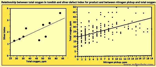
Fig 5 Relationship between total oxygen in tundish and sliver defect index for product and between nitrogen pickup and total oxygen
Nitrogen pickup – The difference in nitrogen content between steelmaking vessels is an indicator of the air entrained during transfer operations. Hence, nitrogen pickup serves as a crude indirect measure of total oxygen, steel cleanliness, and quality problems from reoxidation inclusions. For example, a steel plant restricts nitrogen pickup from ladle to tundish to less than 10 ppm for critical clean steel applications. The oxygen pickup is always many times higher than the measured nitrogen pickup, because of its faster absorption kinetics at the air steel interface. Fig 3 shows relationship between nitrogen pickup and total oxygen. In addition, nitrogen pickup is faster when the oxygen and sulphur contents are low. Hence, for the reduction of the nitrogen pickup, deoxidation is best carried out after tapping. Plant measurements confirm this, as nitrogen pickup reduced from 10 ppm to 20 ppm for deoxidation during tapping to 5 ppm after tapping.
The general conclusion drawn from the data of minimum nitrogen pickup and nitrogen contents measured in LCAK steel at every processing step (except tundish and mould) for several steel plants is that the nitrogen in LCAK steel cast products is around 30 ppm to 40 ppm at the majority of the steel plants. It is controlled mainly by the steelmaking converter or electric furnace operation, but is also affected by secondary steelmaking and shrouding operations. However, the nitrogen pickup is decreasing with passing years, because of new technologies and improved operations. Nitrogen pickup can be normally controlled at 1 ppm to 3 ppm from ladle to the mould. With optimal transfer operations to lessen air entrainment, this pickup can be lowered during steady state casting to less than 1 ppm.
Concentration measurement – For LCAK steels, the dissolved aluminum loss also indicates that reoxidation has occurred. However, this indicator is a less accurate measure than nitrogen pickup since aluminum can also be reoxidized by the slag. The silicon pickup, manganese pickup can be also used to evaluate the reoxidation process.
Lining refractory observation – Analysis of the lining refractory composition evolution before and after operations can be used to estimate inclusion absorption to the lining and the lining erosion. Also, the origin of a complex oxide inclusion can be traced to lining refractory erosion by matching the mineral and element fractions in the slag with the inclusion composition.
Slag composition measurement – Analysis of the slag composition evolution before and after operations can be interpreted to estimate inclusion absorption to the slag. Also, the origin of a complex oxide inclusion can be traced to slag entrpment by matching the mineral and element fractions in the slag with the inclusion composition. However, these methods are not easy because of the sampling difficulties and since changes in the thermodynamic equilibrium are to be taken into account.
Tracer studies for determining exogenous inclusions from slag and lining erosion – Tracer oxides can be added into slags and linings in ladle, tundish, mould, or ingot trumpet, and top compound. Typical inclusions in the steel are then analyzed by SEM and other methods. If the tracer oxides are found in these inclusions, then the source of these inclusions can be decided.
Submerged entry nozzle (SEN) clogging – Short SEN life due to clogging is sometimes an indicator of poor steel cleanliness. The composition of a typical clog during LCAK steel continuous casting consists of Al2O3- 51.7 %, Fe – 44 %, MnO – 2.3 %, SiO2 – 1.4 %, and CaO – 0.6 % , which shows that nozzle clogs are frequently caused by a simultaneous build-up of small alumina inclusions and frozen steel. Hence, SEN clogging frequency is another crude method to evaluate steel cleanliness.
Final product tests
The ultimate measure of cleanliness is to use destructive mechanical tests to measure formability, deep-drawing, and / or bending properties of the final sheet product, or fatigue life of test samples or product samples. Other steel sheet tests include the HIC test and magnetoscopy. Another example is the inclusion inspection method in ultra-sonic fatigue test. These tests are needed to reveal facts such as the potential benefit of very small inclusions (less than 1 micrometer), which are not to be counted against cleanliness.
It can be seen from the above that there is no single ideal method to evaluate steel cleanliness. Some methods are better for quality monitoring while others are better for problem investigation. Hence, it is necessary to combine several methods together to give a more accurate evaluation of steel cleanliness in a given operation.
Since exogenous inclusions can originate from a combination of several sources, methods for their prevention are not likely to be simple. It is only through the correct combination of all these sources and removal mechanisms that the incidence of large inclusions in the steels can be reduced. For the detection of the exogenous inclusions in steel, the methods which are suitable are ultrasonic scanning, microscopic observation, sulphur print, slime (electrolysis), X-ray, SEM, slag composition analysis, and refractory observation.
제조공정
파운드리에서 테스트 및 검사 주강은 최대 탄소 함량이 약 0.75%인 철 합금입니다. 강철 주물은 주형 내의 빈 공간을 액체 강철로 채워서 생산되는 단단한 금속 물체입니다. 그들은 단조 금속으로 생산할 수 있는 동일한 탄소강 및 합금강에서 사용할 수 있습니다. 주강의 기계적 특성은 일반적으로 연강보다 낮지만 화학적 조성은 동일합니다. 주강은 더 적은 단계로 복잡한 모양을 형성할 수 있어 이러한 단점을 보완합니다. 주강의 특성 주강은 다양한 특성으로 생산할 수 있습니다. 주강의 물성은 화학적 조성과 열처리에 따라 크게 변한다.
주철과 주강의 차이점은 무엇입니까? 주물은 설계 세부 사항을 위한 탁월한 능력을 제공하므로 종종 추가 제작 및 조립이 필요하지 않습니다. 여러 유형의 금속 및 합성물을 포함하여 많은 재료를 주조할 수 있지만 특히 철과 강철은 광범위한 응용 분야에서 우수한 기계적 특성을 보입니다. 주철과 강철은 표면적으로 유사하게 보일 수 있지만 생산에서 적용까지 각각 뚜렷한 장점과 단점이 있습니다. 이러한 장점과 단점을 이해하고 적절하게 선택하는 것은 용서할 수 없는 강도와 내구성과 금세 광택을 잃는 파손되거나 변형된 부품의 차이를 의미할