

제조공정

산업 제조
강 연속 주조의 자동화, 계측 및 모델링
액강용 연속주조법은 액강을 압연기에서 후속 압연을 위해 반제품(빌렛, 블룸, 빔-블랭크, 원형 또는 슬래브)으로 응고시키는 공정입니다. 연속 주조기의 기본 작동은 1차 냉각 구역, 분무 냉각 구역, 교정기 등의 작업 그룹을 통해 주어진 조성의 액강을 원하는 모양과 크기의 가닥으로 변환하는 것입니다.
연속 주조 공정은 기본적으로 (i) 주형 위에 위치한 턴디시(tundish)로, 강철 티밍 래들로부터 액체강을 받아 규정된 속도로 주형에 공급하며, (ii) 수냉식으로 구성된 1차 냉각 구역 2차 냉각 구역으로 통과할 때 스트랜드 형태를 유지하기에 충분히 강한 응고된 외부 강철 쉘을 생성하기 위해 액체 강철이 턴디쉬로부터 공급되는 구리 몰드, (iii) 배치된 봉쇄 구역과 관련된 2차 냉각 구역 스틸 스트랜드(여전히 대부분 액체)가 통과하고 스틸 스트랜드의 추가 응고를 위해 물 또는 물과 공기의 혼합물(에어 미스트)이 분사되는 금형 아래, (iv) 구부림 및 직선화 섹션 강철 스트랜드, (v) 응고된 강철 스트랜드를 제거를 위해 원하는 길이로 절단하기 위한 절단 토치 또는 기계적 가위로 구성된 절단 섹션, 및 (vi) 냉각을 위한 런아웃 롤러 테이블 침대를 눕히거나 제품 이동 구역으로 직접 이동합니다.
강의 연속 주조 공정은 열전달, 액강의 응고 공정, 액강의 흐름, 액체에서 고체 상태로의 상전이와 관련된 문제를 포함하는 복잡한 기술 프로세스입니다. 이는 액강의 연속 주조 공정에서 발생할 수 있는 모든 물리화학적 현상의 영향을 포함하는 최적의 공정 제어 시스템을 만드는 데 상당한 어려움을 수반합니다. 이 때문에 연속 주조 공정의 제어는 제강 공정에서 가장 어려운 작업 중 하나입니다.
연속 주조 공정은 복잡성으로 인해 여러 물리적 현상을 동반합니다. 액강 응고 과정은 금형 내부와 2차 냉각 영역에서 금형을 떠난 후 이러한 중요한 현상이 가장 많이 발생합니다. 1차 냉각 구역에서 발생하는 부분 프로세스는 (i) 복잡한 기하학적 영역과 대류에 의해 야기되는 잠긴 입구 노즐 또는 슈라우드를 통한 액강의 난류 유동, (ii) 액강 내부의 열 전달입니다. 영역, (iii) 성형 쉘과 금형 벽 사이의 금형 내 열 전달, (iv) 고체 및 액체 슬래그 층을 통한 열 흐름, (v) 열 응력 형성, (vi) 응고 쉘 관련 수축 강철 응고 과정에서 발생하는 전이, (vii) 응고 현상에 수반되는 열 효과, (viii) 응고 스트랜드에 대한 금형 벽의 기계적 충격, (ix) 금형 벽과 응고 사이에 에어 갭 형성 과정 가닥 및 (x) 원소 분리 효과를 수반하는 응고 영역 내 결정의 형성.
표면 결함의 형성은 2차 냉각 영역에서 발생합니다. 이 영역에서 일어나는 과정은 (i) 액체 코어 영역 내 열 전달(전도 및 대류), (ii) 응고된 쉘 층에서의 열 전도, (iii) 응고 현상을 수반하는 열 효과, (iv) 노즐 시스템에 의한 스트랜드 냉각으로 인한 다단계 열 전달, 스프레이 영역의 수 및 적용된 냉각 유형과 관련, (v) 강 응고 과정에서 발생하는 전이와 관련된 응고 스트랜드의 수축, (vi) 개별 응고 영역(수지상 결정 영역 및 등축 결정 영역)의 형성 및 (vii) 롤과 스트랜드의 접촉과 관련된 응력 형성 및 연속 주조기 롤 사이의 팽창 가능성. 피>
철강 연속 주조의 자동화, 계측 및 모델링을 위한 몇 가지 동인이 있습니다. 이러한 동인에는 품질에 대한 고객 요구 증가, 경쟁 증가, 더욱 엄격한 환경 규정 및 안전 요구 사항 증가가 포함됩니다. 또한 연속 주조기의 전체 생산 시스템은 이전 및 후속 장치와의 공정 일관성을 보장하는 것입니다. 또한, 연속 주조 공정 자동화 시스템은 생산 계획 및 일정, 품질 보증, 보다 전통적인 감독 제어 기능을 포함하는 필수 작업을 수행하기 위해서도 필요합니다.
연속 주조 공정의 공정 제어는 스트랜드 응고 공정의 완전한 제어를 위한 정교한 기기가 필요합니다. 연속 주조기의 측정 시스템은 많은 공정 정보를 제공합니다. 그러나 기계의 개별 지점에서 쉘 두께의 변화 및 야금학적 길이(액체 코어의 길이)와 같은 주요 정보는 누락되었습니다. 따라서 수학적 모델은 연속 주조 공정의 제어 시스템에 매우 중요합니다. 이러한 수학적 모델의 정확성으로 인해 프로세스 중에 기술적 결정을 내리는 데 사용할 수 있습니다.
수학적 모델과 함께 자동화 및 계측 시스템은 연속 주조 제품의 품질을 향상 및 확인하고 다양한 방식으로 기계 가동 중지 시간을 줄입니다. 수학적 모델을 통합하는 전문가 시스템이 개발되었습니다. 계속해서 증가하는 품질 요구와 연속 주조 공정의 잘 알려진 다양한 문제를 해결하기 위한 새로운 아이디어에서 비롯된 새로운 과제는 공정 자동화 및 제어의 여러 발전으로 이어졌습니다.
연속 주조 공정을 위한 최신 자동화 시스템은 여러 수학적 모델을 사용하여 주조 공정의 여러 단계를 시뮬레이션합니다. 이러한 계산을 위한 입력 데이터는 레벨 1 자동화의 특정 전송 어댑터에 의해 실시간으로 획득됩니다. 주조 공정의 대상 매개변수는 주어진 생산 프로그램 또는 작업자가 지정해야 합니다. 전문가 시스템은 프로세스 매개변수의 최적 값을 계산하고, 생산 품질을 제어하고, 기술 프로세스의 다양한 상태에 대한 즉석 모델링을 실행하고, 롤러 및 세그먼트 설정을 확인하는 데 사용됩니다. 전문가 시스템은 레벨 2 자동화의 일부입니다. 데이터 전송을 위한 명확한 소프트웨어 아키텍처와 안정적인 미들웨어 플랫폼은 다양한 자동화 시스템, 전문가 시스템 및 운영자 간의 성공적인 상호 작용에 중요한 역할을 합니다.
HMI(인간 기계 인터페이스)는 생산 프로세스 전반에 걸쳐 작업자를 안내합니다. 운영 직원 상호 작용은 품질 관련 및 안전 관련 활동으로 제한됩니다. 주요 정보의 개요는 메인 디스플레이에 표시되며 세부 사항은 광범위한 전용 화면 세트를 통해 쉽게 액세스할 수 있습니다. 작업자 화면은 작업자가 이해할 수 있는 언어와 단위로 표시됩니다. 전체 시스템은 구성 가능한 응용 프로그램 세트로 구성되며 사용자는 미리 정의된 텍스트를 입력하는 대신 선택할 수 있습니다. 그림은 연속 주조 공정의 일반적인 자동화 시스템을 보여줍니다.
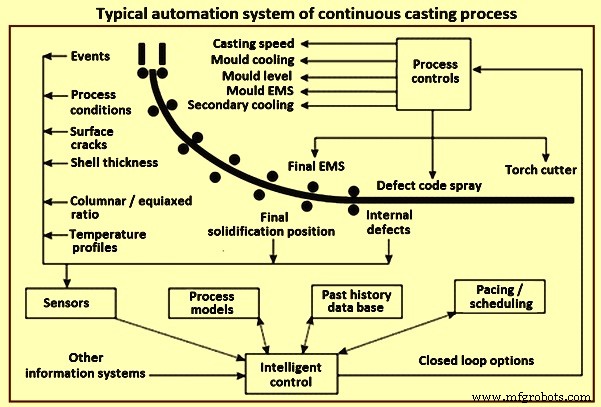
그림 1 연속 주조 공정의 일반적인 자동화 시스템
자동화 시스템의 계층 구조
자동화 시스템의 책임, 요구 사항 및 응답 수준에 대한 다음 분류는 연속 주조기의 기술 프로세스에 대한 자동화 및 제어 시스템을 설계 및 개발할 때 정의됩니다.
레벨 0 자동화 – 개별 단위의 제어로 구성됩니다. 자동화 영역 내의 개별 장치는 연결된 센서, 변환기, 회전 변환기, 드라이브, 제어 장치 및 제어 회로를 사용하여 제어됩니다. 직접 수동 제어는 레벨 0 자동화 시스템에 의해 차례로 처리되는 장치, 드라이브 및 인터록을 통해 수행됩니다. 대부분의 안전 메커니즘도 이 수준에 저장됩니다.
레벨 1 자동화 – PLC(Programmable Logic Controller) 제어를 통해 유닛 그룹을 제어합니다. 레벨 1 자동화 시스템이 처리하는 작업에는 하나의 자동화 영역 내 여러 장치의 제어 시스템이 포함됩니다. 제어 작업은 일반적으로 PLC 제어의 경우 20밀리초(ms) ~ 150ms, 마이크로 컨트롤러(의 경우 예:모션 컨트롤러). 이러한 시스템에 대한 응답 시간의 엄격한 제한으로 인해 복잡한 생산 프로세스 모델을 구현할 수 없습니다. 예를 들어 모바일 장치를 사용한 자재 추적 및 적용 범위 계획과 관련된 작업은 다른 자동화 수준에 위임됩니다.
연속 주조기의 레벨 1 자동화 기능에는 일반적으로 (i) 터렛, 더미 바 카 및 턴디쉬 제어, (ii) 더미 바 위치 결정, (iii) 구동 롤러 조정, ( iv) 너비 조정, 금형 테이퍼 및 금형 레벨 제어, (iv) 1차 및 2차 냉각 시스템에서 선택한 설정점에 따른 공기 및 물 조절
레벨 2 자동화 – 레벨 2 자동화는 프로세스 제어를 위한 것입니다. 레벨 2 자동화 시스템은 생산 프로세스의 효율성과 품질 보증을 결정하는 데 중요한 역할을 합니다. 레벨 2 자동화 시스템은 운영 엔지니어 또는 관련 표준이 미리 정의한 지침과 설정을 사용하여 주조 공정을 관리하고 모니터링합니다. 또한 각 주조 지침에는 목표 제품 품질을 생산하기 위한 최상의 조건을 나타내는 품질 평가 매개변수 세트가 포함되어 있습니다. 일련의 야금 모델을 사용하면 주조 공정을 완전히 자동화할 수 있어 작업자 입력이나 개입의 필요성을 최소화할 수 있습니다. 프로세스 모델은 전체 성능을 최적화하기 위해 모든 학부를 연결합니다.
레벨 2 자동화 시스템은 (i) 생산 품질 보증, (ii) 프로세스 제어 및 레벨 1 자동화 시스템에 대한 명령 및 매개변수 전송, (iii) 자동화된 생산 데이터 수집, (iv) 시뮬레이션 및 기술 프로세스의 통합 수학적 모델을 사용하여 시스템 상태 예측, (v) 자재 추적, (vi) 모바일 장비를 사용한 자재 취급 및 적용 범위 계획 시스템 최적화, (vii) 생산 평가를 포함한 경고 및 결함 표시 시스템 오류 및 설정 시간.
연속 주조 공정에 대한 레벨 2 자동화 시스템 요구 사항에는 (i) 주조 중 공정 매개변수 수집 및 표시, (ii) 스트랜드, 스트랜드 표면 및 가장자리에서 3D 온도 분포 계산이 포함됩니다. 스트랜드 쉘 성장, 응고 길이, 모서리 수축, 스케일 및 기타 주조 특성 계산, (iv) 스트랜드 2차 냉각 시스템의 동적 위치 지정, (v) 세그먼트의 동적 조정 수행(소프트 감소), (vi ) 재료 변경 및 응고 위치 추적, (vii) 운영자 개입 수락 및 전달.
일반적으로 레벨 2 자동화에 포함되는 프로그램 및 모델에는 (i) 스토퍼 메커니즘이 있는 액강 흐름 제어, (ii) 금형 레벨 제어, (iii) 금형 분말 레벨 제어, (iv) 주조 자동 시작, ( v) 금형 이탈 방지 시스템, (vi) 금형, 가닥 및 최종 교반, (vii) 유압 금형 진동, (viii) 열 추적 모델, (ix) 실시간 품질 평가, (x) 절단 최적화 모델, ( xi) 실시간 스트랜드 응고 모델, (xii) 온라인/오프라인 응고 곡선 계산기, (xiii) 동적 기계적 소프트 감소, (xiv) 동적 2차 냉각 제어, (xv) 주조 제품 마킹 머신, (xvi) 광학 제품 인식 시스템, (xvii) 공정 분석 및 시뮬레이션, (xviii) 야금 데이터 관리, (xix) 생산 지연 감지, (xx) 장비 수명 추적, (xxi) 3차 냉각을 포함한 주조 제품 취급 물류 피>
연속 주조 공정을 위한 레벨 2 자동화 제어 기능을 구현할 때 도메인에 대한 다양한 기술 용어를 모델링하기 위해 복잡한 데이터 구조가 사용됩니다. 무엇보다도 스프레이 계획, 공기 계획, 기준 온도 곡선, 주물 분말, 주물 매개변수 데이터 세트, 강종, 화학 기준 분석, 강종 그룹, 균열 및 샘플 절단을 사용하여 문제 영역의 매핑을 다양한 각도에서 검사합니다. 전형적인 야금학적 문제와 관련하여. 또한 수학적 모델, 제어 메커니즘 및 사용자 인터페이스는 스트랜드 안내, 몰드, 세그먼트, 롤, 스프레이 노즐, 2차 냉각 제어 회로 및 냉각 세그먼트. 언급된 용어는 간결한 도메인별 언어를 도입하여 쉽게 설명할 수 있습니다.
연속 주조의 경우 레벨 1 또는 레벨 2 자동화 시스템의 작업은 항상 명확하게 분류될 수 없습니다. 각 개별 자동화 작업의 배치 및 배포에 대한 결론은 입력 매개변수 및 프로세스 데이터의 현지화, 임베디드 모델의 가능한 응답 시간, 필요한 저장 공간 및 자율성 정도에 따라 결정됩니다. 요구 사항은 자재 추적과 같은 두 시스템 간에 자주 분산되며 일부는 안전 연동 장치와 같이 중복되기도 합니다. 두 시스템 모두 일반적으로 각각의 자동화 수준 작업을 위해 설계된 고유한 사용자 인터페이스를 가지고 있습니다.
레벨 3 – 레벨 3 자동화는 생산 계획을 위한 것입니다. 주조 프로그램, 작업 일정 및 준비 또는 매장 관리와 같은 생산 계획의 생성과 유지 관리 계획, 종료 시간 및 유지 관리 작업을 다룹니다.
분산 레벨 2 자동화 시스템의 소프트웨어 아키텍처 – 레벨 2 자동화 시스템이 충족해야 하는 중요한 요구 사항은 레벨 1 제어 시스템, 레벨 3 계획 시스템, 연결된 데이터베이스 및 연속 주조기 운영 인력과 통합 수학 모델의 안정적이고 안전한 통신입니다. . 레벨 2 자동화를 설계하고 구성하는 동안 다양한 구성 요소, 해당 인터페이스 및 연결된 데이터 소스가 중요하며 모든 단일 구성 요소의 동작 논리를 과소평가해서는 안 됩니다.
레벨 2 자동화 시스템에 통합된 수학적 생산 프로세스 모델은 프로세스 제어 시스템의 핵심을 형성합니다. 프로세스의 실제 상태를 모니터링하여 레벨 1 자동화 시스템의 실제 값을 모델에 지속적으로 제공할 수 있습니다. 한편, 데이터는 단기 계획 결과와 레벨 3 자동화 시스템의 자재 및 주문 데이터로 보완됩니다. 연산 결과와 생산 공정의 전체 보기는 사용자 인터페이스에서 작업자를 위해 연속 주조기에서 표시됩니다. 속도 설정과 같은 레벨 1 자동화 시스템 입력 마스크와 제어 체제(기준 온도 및 스프레이 계획 제어) 변경과 같은 레벨 2 자동화 시스템 사용자 인터페이스를 모두 사용하여 작업자가 필요한 모든 공정 제어 개입을 수행할 수 있습니다. .
다양한 소프트웨어 아키텍처 패턴이 이러한 시스템을 구현하는 데 사용되며 여기에는 모델(다중 에이전트 아키텍처), 이벤트 및 메시징 디스패처(이벤트 기반 아키텍처), 분산 서비스(서비스 지향 아키텍처)가 포함됩니다.
계측기
연속주조의 초창기부터 연속주조기에 기구가 사용되어 왔다. 기계는 터렛 또는 레이들 카와 주조 제품용 런아웃 롤러 테이블 사이의 연속 주조기의 모든 주요 구성 요소에 사용됩니다. 기기는 그림 2에서와 같이 국자, 턴디쉬, 금형, 2차 냉각 영역, 복사 영역 및 런아웃 롤러 테이블의 변수를 모니터링하기 위해 연속 주조 기계에서 광범위하게 사용됩니다. 제어 주조 매개변수는 연속 주조 기계의 생산성과 품질을 크게 향상시킨 주요 요인 중 하나로 인정받고 있습니다.
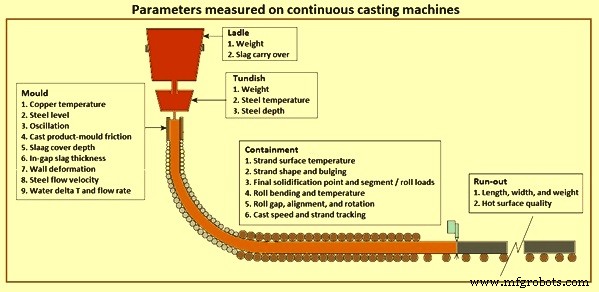
그림 2 연속 주조기에서 측정한 매개변수
기기는 모든 제어 및 자동화 시스템에 매우 중요하며 최신 생산성 및 품질 표준을 달성하기 위한 기기의 기여도는 아무리 강조해도 지나치지 않습니다. 기기는 제어 및 자동화 시스템의 '눈'이며, 현재 기술로 영구 기기는 공정 및 품질 관리 시스템에서 가장 중요한 국자, 턴디시 및 금형 변수를 '확인'하는 데 사용할 수 있습니다.
연속 주조 공정에서 기기의 주요 기능은 (i) 연속 주조의 기계적 및 야금학적 기능의 성능을 제어하는 데 사용되는 매개변수를 측정하고, (ii) 각 주조 섹션에 대한 품질 등급을 지정하고, (iii) ) 작동 및 기계 문제 진단, (iv) 제품 품질 및 생산성을 주조 기계 설계 및 작동과 연관시키는 지식 개발.
연속 주조기에 사용되는 기기의 수와 정교함은 빠르게 증가하고 있습니다. 급속한 성장의 주된 이유는 더 높은 생산성 및 주조 제품 품질에 대한 계속 증가하는 요구와 최신 온라인 디지털 컴퓨터의 가용성입니다. 품질 및 생산성 요구 사항이 가장 엄격한 슬래브 주조 기계의 경우 특히 그렇습니다. 이전에는 금형 방식과 매개변수가 제품 품질과 생산성에 가장 큰 영향을 미치기 때문에 금형 계측에 중점을 두었습니다. 그러나 최근에는 국자, 턴디쉬, 격납 및 주조기 런아웃 롤러 테이블에 대한 기기의 개발 및 적용에 상당한 진전이 있었습니다.
연속 주조기의 2차 냉각 구역의 스프레이 챔버 내에서 발견되는 위험한 환경을 감안할 때 주조기 제어 시스템이 이 공정에서 스트랜드 표면 온도와 같은 중요한 공정 변수의 변화에 자주 '무시'된다는 것은 놀라운 일이 아닙니다. 존. 여기에 사용된 계측은 일반적으로 일시적인 특성을 가지므로 실험적으로 사용됩니다. 기타 중요한 기기로는 롤 간 팽창, 응고된 쉘의 두께, 몰드/스트랜드 마찰을 측정하는 데 사용되는 기기가 있습니다.
연속 주조 공정 모델링
강 연속 주조 공정을 모델링하는 것은 매우 복잡한 작업이며 다양한 유형의 수학적 모델을 사용하여 수행할 수 있습니다. 현재로서는 연속 주조의 전체 과정에서 발생하는 모든 영향을 동시에 포착하여 단일 종합 수치 모델의 형태로 제시하는 것이 불가능합니다. 연속주조 공정 모델링에 적용되는 자연분할은 실제 용강을 주조할 때 발생하는 문제점을 파악하거나, 기존 기술을 개선하기 위해 공정의 선택된 부분에 집중하려는 시도와 관련이 있다.
문제 해결의 초기 단계에서 모델 유형의 올바른 선택과 해결된 문제의 클래스에 적용하기 위한 관련 가능성은 어려운 도전이었습니다. 이론적으로 더 복잡한 모델(즉, 더 '지능적인')이 주조 공정의 주요 기술 매개변수에 대한 질문에 쉽게 답할 수 있습니다. 그러나 실제로는 여러 가지 제한 사항이 있습니다. 복잡한 모델이 올바른 것으로 검증되었다고 가정하면 최상의 경우 컴퓨팅 시간의 불필요한 연장이 필요합니다. 이는 모델이 정의된 문제를 해결하는 데 필요한 것보다 훨씬 더 많은 매개변수를 계산한다는 사실에서 비롯됩니다. 사용된 도구의 '지능'과 세트 문제의 복잡성을 동기화하지 않음으로써 발생하는 두 번째 위험은 모델 매개변수 및 프로세스 데이터와의 상관 관계 검증 문제입니다. 모델이 정교할수록 더 많은 매개변수와 측정할 수 없는 매개변수의 발생 위험이 높아집니다. 마지막 의견은 필요한 모델 매개변수의 값에 대한 지식을 획득하는 전략의 문제에 관한 것입니다. 연속 주조 공정 모델링에 대한 수년간의 경험에 따르면 최상의 선택은 모든 측정 가능한 모델 매개변수의 실험적 측정입니다. 온도, 강철의 열전도율, 점도 등의 함수로 주조된 강철의 비열 형태의 매개변수로 설명할 수 있습니다.
물리적 모델링 – 물을 사용하여 액강을 시뮬레이션하는 것과 같은 연속 주조 공정의 물리적 모델링을 통해 연속 주조 공정 중 액강의 유동 거동에 대한 상당한 통찰력을 얻을 수 있습니다. 연속 주조 공정에서 유체 흐름에 대한 이전의 이해는 주로 물리적 물 모델을 사용한 실험을 통해 이루어졌습니다. 이 기술은 프로세스에서 구현하기 전에 새 구성의 효과를 테스트하고 이해하는 데 유용한 방법입니다. 전체 규모 모델에는 운영자 교육 및 이해를 제공하는 중요한 추가 이점이 있습니다.
물리적 모델의 구성은 중요한 관심 현상을 지배하는 기하학적 구조와 힘 균형을 모두 일치시켜 모델과 실제 프로세스 사이의 특정 유사성 기준을 충족하는 것을 기반으로 합니다. 물 모델로 액강 유동 패턴을 재현하기 위해 지배력 간의 모든 비율은 두 시스템에서 동일해야 합니다. 이렇게 하면 모델과 철강 프로세스 간의 속도 비율이 모든 위치에서 동일하게 유지됩니다. 무차원 그룹의 크기는 두 힘의 상대적 중요성을 나타냅니다. 매우 작거나 매우 큰 그룹은 무시할 수 있지만 주조 과정에서 중간 크기의 모든 무차원 그룹은 물리적 모델에서 일치해야 합니다. 이러한 일치를 달성하려면 적절한 기하학 척도와 유체를 선택해야 합니다.
물과 강철의 운동학적 점도가 매우 유사하다는 것은 다행스러운 일입니다. 따라서 본격적인 물 모델을 구성하여 Reynolds와 Froude 수를 동시에 일치시킬 수 있습니다. 이 두 가지 기준을 충족하면 연속 주조 노즐 및 금형과 같은 등온 단상 흐름 시스템을 모델링하는 데 합리적인 정확도를 달성하기에 충분하며 이는 큰 성공을 거두었습니다.
실물 크기 모델은 기계 구성 요소의 손쉬운 테스트와 작업자 교육의 추가 이점이 있습니다. 실제로 두 시스템의 속도가 완전한 난류 흐름과 매우 높은 레이놀즈 수를 생성할 수 있을 만큼 충분히 높기만 하면 모든 기하학적 규모의 물 모델은 대부분의 흐름 시스템에 대해 합리적인 결과를 생성합니다. 턴디쉬 및 몰드 노즐을 통한 흐름은 중력에 의해 구동되기 때문에 Froude 수는 일반적으로 유압 헤드와 형상이 모두 동일한 양으로 조정되는 이러한 시스템의 모든 물 모델에서 충족됩니다.
물리적 모델은 때때로 열 유사도 기준을 충족해야 합니다. 예를 들어, 레이들과 턴디쉬의 정상 흐름의 물리적 흐름 모델에서 열 부력은 수정된 Froude 수의 크기로 표시되는 지배적인 관성 유도 흐름에 비해 크므로 모델에서 동일하게 유지되어야 합니다. 액체 강철 시스템에서와 같이. 속도를 추정하기 어려운 국자에서는 Reynolds 수의 제곱을 수정된 Froude 수로 나눈 값을 Grashof 수라고 하는 것이 편리합니다. 관성은 금형에서 지배적이므로 열 부력은 무시할 수 있습니다. 열 부력의 상대적 크기는 전체 규모의 온수 모델에서 일치시킬 수 있습니다. 그러나 이는 열손실을 지배하는 현상이 유체전도도, 비열, 용기벽전도율 등의 물성에 따라 달라지며, 이는 모델과 강재 용기에 따라 다르기 때문에 쉽지 않습니다. 저속, 과도 또는 응고와 관련된 시스템과 같은 다른 시스템에서는 열 전달에 중요한 몇 가지 다른 유사성 기준을 동시에 충족하는 것이 사실상 불가능합니다.
연속 주조 공정의 복잡성과 그림 3과 같이 이를 지배하는 현상으로 인해 물리적 모델을 갖기가 어렵습니다. 그러나 컴퓨터 하드웨어 및 소프트웨어의 성능이 향상됨에 따라 수학적 모델링은 연속 주조 공정의 모든 측면을 제어하는 데 중요한 도구가 되었습니다.
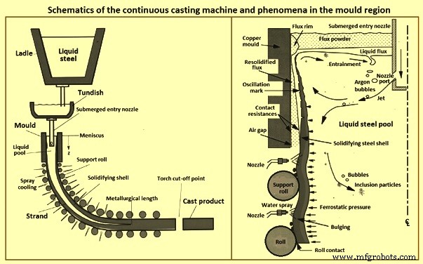
그림 3 연속 주조의 개략도와 금형 영역의 현상
전산 또는 수학적 모델링 – 현재에는 계산 비용이 감소하고 상용 모델링 패키지의 기능이 증가함에 따라 액체강의 연속 주조 공정의 복잡한 재료 공정 단계를 이해하기 위한 추가 도구로 수학적 모델을 더 쉽게 적용할 수 있습니다. 전산 모델은 등온수 모델에서는 어려운 열전달, 입자 운동 및 2상 흐름과 같은 다른 현상으로 쉽게 확장할 수 있는 장점이 있습니다. 계산 모델은 또한 액강이 경험하는 유동 조건을 보다 충실하게 표현할 수 있습니다. 예를 들어, 물가 모델을 나가는 흐름을 방해하는 물리적 바닥이 필요하지 않으며 이동하는 응고 쉘의 존재를 고려할 수 있습니다.
수학적 모델은 이제 연속 주조 공정에 중요한 대부분의 현상을 시뮬레이션할 수 있습니다. 여기에는 (i) 아르곤 기포, 열 및 용액 부력의 영향을 받는 복잡한 기하학적 구조(입구 노즐 및 스트랜드 액체 풀)에서 완전 난류, 과도 유체 운동, (ii) 분말과 강철 상 내부 및 사이의 열역학적 반응, (iii) 강철의 상단 표면에 떠 있는 액체 및 고체 플럭스 층 내의 유동 및 열 전달, (iv) 표면 장력, 진동 및 중력 유도의 영향을 포함하는 자유 액체 표면 및 계면의 동적 운동 파동 및 여러 단계의 흐름, (v) 난류 액체강을 통한 과열도의 이동, (vi) 용질의 이동(등급 변경 중 혼합 포함), (vii) 부력의 영향, 난류 상호 작용 및 노즐 벽, 기포, 응고되는 강철 벽 및 상단 표면에 대한 개재물의 가능한 갇힘, (viii) 메니스커스 영역의 열, 유체 및 기계적 상호 작용 응고 메니스커스, 고체 슬래그 림, 침투하는 액체 플럭스, 액체 강, 분말 층 및 개재 입자 사이, (ix) 응고 강 쉘을 통한 열 전달, 쉘과 금형 사이의 계면(분말 층 및 증가하는 에어 갭 포함) , 및 구리 몰드, (x) 쉘과 몰드 사이의 틈으로 분말의 대량 수송, (xi) 몰드 벽 및 지지 롤의 왜곡 및 마모, (xii) 용융물 및 몰드에 대한 고체 결정의 핵 생성 벽, (xiii) 덴드라이트, 결정립 및 미세 구조의 성장, 상 변형, 침전물 형성 및 미세 편석을 포함하는 강철 쉘의 응고, (xiv) 열 수축, 상 변형 및 내부 변형으로 인한 응고 강철 쉘의 수축 응력, (xv) 외력(금형 마찰, 지지 롤 사이의 팽창, 철수 및 중력)으로 인한 응고강 쉘 내 응력 생성, (xvi) 열 변형, 크리프 및 플라스 미시적 규모와 거시적 규모 모두에서 밀도(온도, 등급 및 냉각 속도에 따라 다름), (xvii) 균열 형성 및 (xviii) 결합된 분리.
연속 주조 공정의 엄청난 복잡성으로 인해 이러한 모든 현상을 한 번에 함께 모델링하는 것이 불가능합니다. 따라서 합리적인 가정을 하고 덜 중요한 현상을 분리하거나 무시할 필요가 있습니다. 정량적 모델링은 특정 관심 문제에 영향을 미치는 모든 현상을 통합해야 합니다. 따라서 각 모델에는 특정 목적이 필요합니다. 지배 방정식이 선택되면 일반적으로 유한 차분 또는 유한 요소 방법을 사용하여 이산화되고 해결됩니다. 적절한 수치 검증을 수행하는 것이 중요합니다.
수치 오류는 일반적으로 비선형 방정식을 풀 때 계산 영역이 너무 조잡하거나 불완전한 수렴에서 발생합니다. 알려진 테스트 문제를 해결하고 격자 독립 솔루션을 달성하기 위해 메쉬 미세 조정 연구를 수행하는 것은 모델을 검증하는 데 도움이 되는 중요한 방법입니다. 마지막으로, 모델은 매개변수 연구를 위한 실제 프로세스의 정량적 예측을 하기 전에 실험실 및 공장 규모 모두에서 실험적 측정과 비교하여 확인해야 합니다.
모델의 최종 테스트는 결과가 구현될 수 있고 철강 제품의 결함 방지와 같은 개선이 달성될 수 있는지입니다. 이 구현을 위해서는 궁극적으로 식물 실험이 필요합니다. 시험은 물리적 모델, 수학적 모델, 문헌 및 이전 경험을 포함하여 사용 가능한 모든 소스에서 제공된 통찰력을 기반으로 수행되어야 합니다. 계산 능력이 증가함에 따라 수치 시뮬레이션 도구의 기능이 계속 발전함에 따라 모델링은 첨단 연속 주조 공정의 미래 발전에서 점점 더 중요한 역할을 합니다. Modelling can augment traditional research methods in generating and quantifying the understanding needed to improve any aspect of the process. Areas where advanced computational modelling plays a crucial role in future improvements include (i) transient flow simulation, (ii) mould flux behaviour, (iii) taper design, (iv) on-line quality prediction and control, especially for new problems and processes such as high-speed billet casting, thin slab casting, and strip casting.
Future advances in the continuous casting process are not going to come from models, experiments, or plant trials. They are going to come from ideas generated by people who understand the process and the problems. This understanding is rooted in knowledge, which can be confirmed, deepened, and quantified by tools which include computational models. As the computational tools continue to improve, their importance is increasing in fulfilling this important role, leading to future process advances.
The assumed computing objective and the required accuracy are to be the key in selecting the model. In several cases, the desired information is knowledge of the metallurgical length of the strand and the dynamics of changes in the shell thickness. This is the case when determining a place for carrying out the so‐called soft reduction operation. As can happen when the strand casting speed needs to be changed, a procedure allowing a new cooling intensity to be determined is needed. A problem like this does not need answering a series of questions related to stress occurring in the strand, the structure formed, or potential cast strand defects. Thus, it is understandable that the model is naturally simplified to a form, which still provides a credible answer to the questions which needs solution.
Some of the important models used in the automation and control of the continuous casting process are given below. The models are normally incorporated at the Level 2 automation level.
Dynamic secondary cooling control – There is a third dimension in the dynamic secondary cooling control. The model set up takes the precision and control possibilities to the next dimension allowing completely new philosophies for secondary cooling and soft reduction. When setting up the secondary cooling system, it is prerequisite to consider all known parameters which have a known influence to the calculation of 3-dimensional temperature profile of the strand. All different nozzle types are measured at the nozzle test stand to evaluate the spray water distribution. This derived information is input to the maintenance and setup system (MSS) of the 3D model. The visualized spray distribution can be seen in the maintenance system.
The exact positions of the nozzles in the cooling zones are entered and the spray distribution of one zone can be seen in the MSS. The heat removal of a cooling zone is calculated considering the heat removal of the spray water, rolls, and heat radiation. The MSS allows all cooling-relevant settings to be configured in such a way that the spray-water distribution in the cooling zones and the application of cooling practices are optimized for continuous casting machines. Metallurgical know-how can be easily incorporated into the automation setup. A built-in off-line simulation system enables comprehensive testing of new parameter settings prior to application in the production process.
The Level 2 automation system for secondary cooling provides a mathematical model for calculating the temperatures on the strand surface and inside the strand as a function of the spray plan to be used, the interpolation points in the reference temperature curve, or in relation to time changes for the spray water quantities across the complete machine. The dynamic secondary cooling control system can handle three control regimes namely (i) temperature control, (ii) strand age, and (iii) spray plan control.
In the temperature control regime the dynamic secondary cooling control system calculates the volumes of water for strand secondary cooling which are needed to maintain the specified reference temperature on the strand surface. The strand age regime is one way of controlling the secondary cooling process, taking into account the change in parameters over a given period of time. With the spray plan control regime a spray plan is produced for secondary cooling whereby preset spray water volumes correspond to a specific casting speed. As the change in casting speed takes effect, the spray water volumes are also immediately modified, and the resulting temperatures on the strand surface are displayed to the continuous casting machine operator. If temperature scanners are used in the plant, the dynamic secondary cooling control system is able to adapt to the values delivered by the scanners, so that the coefficients of the strand temperature field calculation can be adapted to the values measured.
Dynamic 3D secondary cooling system – The first-generation dynamic solution was characterized by a two-dimensional temperature calculation of the strand centre. The strand corners were largely neglected by the process model. Continuous improvements in computer performance have now made it possible to calculate the temperature at any point within the entire strand in real time, in a full three-dimensional mode and in a sufficiently fine discretization yielding very detailed temperature profiles as can be seen for strand surface and strand centre.
The model is based on an explicit finite-volume approximation which solves the heat transfer equation and takes into consideration temperature-dependent material properties such as density as well as the position-specific cast product thickness and width. Dynamic 3D secondary cooling system accurately assesses the heat transfer from the cast product surface resulting from radiation, heat transfer to the rolls, natural convection and spray water. Further, the dynamic 3D secondary cooling system can be applied for both spray cooling and air-mist cooling and takes into account the spray distribution pattern of the nozzles and the actual spray water temperature. This ensures an accurate spray-cooling heat transfer prediction to temperatures below 700 deg C when the Leidenfrost phenomenon disappears. The result is an even more precise determination of the strand surface-temperature profile and the final point of strand solidification.
Based on the precise temperature calculations the dynamic 3D secondary cooling system allows specifying the desired surface temperature not only along the strand length, but also across the strand width. Even individual control of the water flow and positioning of each cooling nozzle is possible. The control algorithms of the dynamic 3D secondary cooling system calculate the water flow set-points to achieve the target strand surface temperature values. Pyrometer measurement results show an excellent fit in between calculated and measured lateral strand temperature profile.
Application of the dynamic 3D secondary cooling system allows introducing completely new philosophies to set up cooling practices for upcoming challenges in continuous casting. The combination with moveable spray nozzles (3D sprays) yields unprecedented quality results.
The advanced secondary cooling dynamic 3D model derives correct water flow rates even in transient casting situations such as steel grade changes, casting speed variations, different tundish temperatures, tundish exchanges, and at the beginning and end of a casting sequence. The water flow rate for each cooling zone is calculated to maintain a defined surface temperature profile throughout the entire casting sequence. The maintenance system allows the process engineer to change cooling practices easily and introduce continuous casting shop specific cooling expertise. The off-line simulation system is used to test the effect of the new settings in various casting situations before utilization in the production process.
Dynamic phase calculation of material properties – In order to calculate a 3-dimensional temperature profile of the strand, material properties like enthalpy, solid fraction, density, and conductivity as a function of the temperature are to be known. In case, these properties are experimentally known for a given steel grade composition, these functions can be entered by the process engineers in the MSS, which is very time-consuming. Normally the process engineer does not know these thermo-physical properties. The software model calculates all the thermo-physical data used by 3D model. Dynamic phase calculation of material properties is available as an on-line tool to determine the material properties for the current steel grade analysis.
The traditional approach is to define the thermo-physical properties for grade groups with a pre-defined concentration range of the chemical analysis. Using the dynamic phase calculation, these data can be calculated for each individual steel grade. This makes the prediction of quantities such as the point of complete solidification on the strand and the temperature distribution of the strand during casting more accurate and hence allows for precise metallurgical treatments which can lead to an improved quality of the products. Further, the model indicates whether the current analysis of the steel is peritectic or not and alerts the operator in the event of an unexpected peritectic grade. This can reduce the risk of breakouts and improves quality.
The dynamic phase calculation is based on thermodynamical models. The liquid-solid phase transformation in the high temperature range is described by a Gibbs free energy model in combination with a micro-segregation model. For solid-solid phase transformations in the low temperature range an Avrami type model is employed. The free parameters of the models are determined with the help of experimentally measured quantities. Using off-line simulations of dynamic phase calculation together with the 3D model allows metallurgical development of new steel grades.
Traditionally the steel grades are grouped and a typical chemical analysis for the group is used to determine the material properties. With dynamic phase calculation, the material properties are derived from the actual steel analysis. Calculations can show that there can be a difference in the point of final solidification of half a meter or even more by comparing the results of the actual steel analysis versus the grade group analysis. This fact shows the importance of having an on-line calculation of the actual steel grade in order to improve the quality of the cast products.
Dynamic gap soft reduction – Dynamic gap soft reduction stands for dynamic roll-gap adjustment in the continuous casting process. This is made possible by specially designed strand-guide segments – known as ‘smart segments’ in which the roller gaps can be remotely adjusted for strand thickness changes and for improved internal strand quality. On the basis of the on-line information provided by the dynamic 3D thermal-tracking model, the dynamic gap soft reduction dynamically calculates the set points of the adjustable roll gap.
Supervision of the roll engagement, depending on the state of solidification (liquid, mushy, or solid) and the calculated strand-thickness profile, is a decisive factor for precise roll adjustments and thus improved product quality. An optimized roll engagement also reduces excessive forces on the strand and decreases roller wear. The more accurate control of the roller gaps allows additional casting strategies to be implemented such as liquid-core reduction and intentional bulging soft reduction. 즉. intentional dynamic gap increase before the soft reduction area allows for higher thickness reduction in this area. This further improves the casting flexibility and the product quality.
Dynamic gap soft reduction makes it possible to freely define scenarios for start-up, tundish change, and tail out strategies based on the strand thickness, steel grade, and casting status. In this way roll damage and production interruptions, which can arise from the different casting behaviour of the cold strand head or end, can be avoided.
Nozzle expert for early clogged nozzle detection – Cooling water is sprayed through nozzles onto the strand with the objective of achieving uniform cooling of the steel. However, if one or more of these nozzles are clogged, then a section of the strand cannot be uniformly cooled to the required temperature. This can lead to surface defects, and the cast product possibly has to be down-graded. The issue of changing segments in the continuous casting machine is also a source of difficulty. Hoses can easily be ruptured or jammed. Aware of the consequences of leakages or clogged nozzles, maintenance personnel spend a large number of working hours checking whether nozzles are operating properly.
The nozzle expert helps to detect clogged nozzles and broken hoses in the continuous casting machines and thus ensures that the strand is evenly cooled for high quality steel production. It automatically monitors the condition of the nozzles during the casting process. The model can also be manually activated during casting breaks. The advantage is that nozzle status can be checked following maintenance work or segment changes and immediately repaired before the casting process is restarted.
The model calculation considers parameters like nozzle type (measuring results from the nozzle test stand), height between pressure measuring device, water pressure, pipe lengths, pipe diameters, and nozzle positions. Any modifications to the secondary cooling system e.g. use of different nozzle types needs a change in the set-up of the nozzle expert in order to get correct computational results.
The nozzle expert is based on statistical models and indicates the clogging ratio in each zone (e.g., zone 2 nozzles clogged 10 % with a probability of 96 %). Operators need only to inspect zones for which an alarm is generated. Calculations begin automatically with the start cast signal, and the condition of the nozzles is monitored throughout the casting process. Several alarms help to detect leakages, clogged nozzles, and even falsely installed nozzles on a segment.
Inter-mix expert – It improves yield by prior simulations. During sequence casting, a mixing of steel grades takes place in the tundish and therefore in the strand with each ladle change. On the basis of the chemical composition of the steel, the inter-mix expert calculates whether the mixed steel zones can be used for the foreseen product application or if the steel has to be downgraded or even scrapped. Information acquired from tundish flow experiments combined with analysis results of steel samples taken from solidified products ensures a high degree of accuracy of Inter-mix predictions with respect to the actual composition of the mixed steel zones.
The inter-mix expert determines traces of the previously cast heat present in the current heat. Steel mixing takes place not only in the tundish but also in the mould and upper parts of the strand. Mixing in these areas is evaluated by a mix-box-type sub-model of inter-mix which makes it possible to calculate the chemical composition of the steel at any position along the cast strand.
Tundish changes or the use of separator plates are treated individually. Inter-mix calculations are cyclically performed for selected chemical elements starting with the ‘ladle open event’ of a new heat. The final decision about the compatibility of heats cast in sequence is performed by the heat-assignment function of inter-mix. The concentration profiles of certain critical elements which have an impact on the final product disposition (prime, downgraded, or outright rejection) are determined. A deviation is detected if one of the critical elements does not match the steel-grade specification.
The full benefit from the inter-mix model is achieved by combining the model output with the yield expert model which assures maximum prime quality yield by applying cut-length optimization to incompatible steel areas along the strand which are designated as scrap.
Process engineers work with the powerful simulation environment, which makes it possible to simulate any combinations of different steel grades. Input parameters like analysis, tundish weight, and dimensions of the strand can be easily entered and modified and the computed results are made visible in the HMI. Graphs are displayed for single analysis elements or combinations of more elements. Valuable information like volume concentration, mixed steel length, scrap length, and heat ranges on the strand are shown on the bottom of the graphs.
Configuration of the model can be easily done in the MSS. The process engineer can choose which chemical elements are to be used to determine the inter-mix for any grade link. A powerful simulation environment allows simulating the mixing behaviour of two different grades and the computed volume concentration, calculated analysis along the strand, and heat ranges including possible scrap sections are displayed.
Speed expert – The speed expert model is for the optimum casting speed in any casting situation. Selection of a proper casting speed on the continuous casting machine is of high importance. Several aspects (e.g. quality, safety, machine limits, and production requirements) influence the choice of the casting speed. These different aspects are frequently contradictory such as increase in production calls for a high casting speed whereas the safety requirements limit the casting speed. Normally, several continuous casting shops have self-made software solutions to calculate the casting speed considering different aspects. The aim of the speed expert is to cover most aspects and to provide an easy maintenance tool which enables the process engineer to adjust the behaviour of the speed expert to the special needs.
The speed expert calculates cyclically the optimum casting speed. The calculation of the casting speed is based on various rules, which consider the different aspects and are specified in the speed expert practice. Each rule determines a speed range which satisfies its requirements. The speed expert first determines the inter-section of all these speed ranges. If the inter-section is not empty, then it selects a casting speed depending on the predefined strategy, which can be maximum speed, aim speed, or avoid speed changes as long as actual casting speed is in the valid range. If there is a conflict between the different rules, then the inter-section is empty. In this case the pre-selected conflict resolve strategy is applied which can be (i) priority (lower priority rules are to be neglected till a solution can be found), or (ii) minimum of maximum speed (the smallest of all maximum speeds is to be selected).
On the on-line HMI the casting machine operator can view the speed ranges of all rules and the derived optimum casting speed. The casting operator can change the priorities of the different rules, the strategy, and the conflict resolve strategy to fine adjust the calculation if necessary. Speed set-points are sent to Level 1 and can be executed automatically.
MSS is used to define the speed expert practice considering (i) quality related rules consisting of quality expert rule, minimum / aim / maximum speed for the steel grade, superheat, Mn/S ratio, low tundish weight, and optimum soft reduction, (ii) production related rules consisting of heat pacing, start cast, and clearing, and (iii) safety related rules consisting of machine protection, and forecast calculation for minimum and maximum speed.
Optimum soft reduction can be achieved if the final point of solidification is at the end of a strand segment. A pre-calculation assuming steady state conditions determines the required casting speeds for each strand segment.
Yield expert – The aim of the yield expert is to minimize scrap and to optimize the yield. It considers scrap portions, quality defects, weight restrictions, sample cuts, and width changes while producing the maximum number of scheduled products. The important features of the yield expert are (i) optimization of product length or product weight in the case of scrap sections or quality-related defects, (ii) scheduling of mould width adjustments, (iii) scrap section allocation algorithms, (iv) optimization steps can be switched on-line and off-line, and (v) replay of cut-to-length optimization steps, even in actual production situations
Quality expert – Quality expert determines the definitions necessary for the quality-related process parameters, tracks the actual data during production, predicts the quality of the cast products, and automatically determines the subsequent product disposition. It supports the continuous casting machine operators by on-line quality alerts and a preview of the quality of the cast strands in the casting machine. Quality expert is of two distinct types distinguished by basic or comprehensive product quality rating capability.
All the tracked information and calculation results can be transferred from the production module of the quality expert to the so-called discovery system. This system is dedicated to the long-term archiving and evaluation of the huge amount of information tracked.
제조공정
제조 산업에서 사용되는 다양한 주조 공정이 있습니다. 이러한 모든 공정에는 고유한 장점과 단점이 있어 특정 주조에 적합합니다. 쉘 몰드 주조라고도 하는 쉘 몰딩은 가장 적합한 주조 중 하나입니다. 복잡하고 기타 얇은 섹션에 대한 공정. 이 프로세스는 높은 정확도와 더 나은 표면 조도를 제공합니다. 다양한 주조 산업에 적합한 이 주조 공정의 주요 장점 중 하나는 쉽게 자동화할 수 있다는 것입니다. 이러한 모든 장점으로 인해 이 프로세스는 모든 산업 분야에 다양하고 쉽게 채택할 수 있습니다. 쉘 몰드 주조 공정은 모래와 수지의 혼
SKD11 다이스틸은 일본의 공구강입니다. 재료 열처리 경도:hrc58-60 SKD11은 일종의 고탄소 및 고크롬 합금 공구강입니다. 열처리 후 높은 경도, 연삭성, 강한 경화성 및 우수한 치수 안정성을 갖습니다. 좋은 기계 가공성, 미세하고 균일한 탄화물 입자, 화학 원소인 몰리브덴과 바나듐의 특수 첨가로 인해 담금질 균열에 대해 걱정할 필요가 없습니다. SKD11 특정 성능 A) 고온 강도 및 인성, 우수한 내마모성, 쉬운 절단; B) 강도, 인성 및 내열성 균형이 우수한 냉간 가공 다이 강, 다) 진공 탈기 정제를