

verilog

산업 제조
wire 유형의 신호 또는 데이터 유형과 같은 유사한 연결에는 값의 지속적인 할당이 필요합니다. 예를 들어, 브레드보드의 조각을 연결하는 데 사용되는 전선을 생각해 보십시오. 전선의 한쪽 끝에 +5V 배터리를 인가하면 전선의 다른 쪽 끝에 연결된 부품에 필요한 전압이 공급됩니다.
Verilog에서 이 개념은 assign wire 또는 데이터 유형과 같은 다른 유사한 와이어는 값으로 연속적으로 구동될 수 있습니다. 값은 상수이거나 신호 그룹으로 구성된 표현식일 수 있습니다.
할당 구문은 assign 키워드로 시작합니다. 단일 신호 또는 다른 신호 네트의 연결일 수 있는 신호 이름이 뒤에 옵니다. 추진력 및 지연 선택 사항이며 실제 하드웨어로 합성하는 것보다 데이터 흐름 모델링에 주로 사용됩니다. 오른쪽의 표현식 또는 신호는 평가되어 왼쪽의 net 또는 표현식에 할당됩니다.
assign <net_expression> = [drive_strength] [delay] <expression of different signals or constant value>
지연 값은 게이트에 대한 지연을 지정하는 데 유용하며 실제 하드웨어에서 타이밍 동작을 모델링하는 데 사용됩니다. 값이 평가된 값으로 네트를 할당해야 하는 시기를 지정하기 때문입니다.
assign를 사용할 때 따라야 하는 몇 가지 규칙이 있습니다. 문:
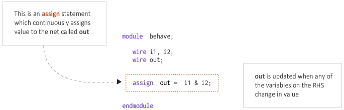
assign 명령문은 연속 할당이라고도 하며 항상 활성 상태입니다.
다음 예에서 호출된 네트는 신호 표현에 의해 연속적으로 구동됩니다. 논리 AND &가 있는 i1 및 i2 식을 형성합니다.
대신 와이어를 포트로 변환하여 합성하면 합성 후 아래와 같은 RTL 회로도를 얻을 수 있습니다.
<노스크립트>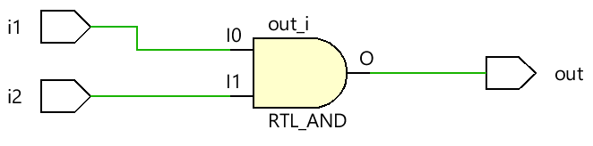
연속 할당 문은 Verilog에서 조합 게이트를 나타내는 데 사용할 수 있습니다.
아래에 표시된 모듈은 두 개의 입력을 취하고 assign를 사용합니다. 부분 선택 및 다중 비트 연결을 사용하여 출력 z를 구동하는 문. 각 경우를 모듈의 유일한 코드로 처리하고, 그렇지 않으면 많은 assign 동일한 신호에 대한 명령문은 확실히 출력을 X로 만들 것입니다.
module xyz (input [3:0] 	x,		// x is a 4-bit vector net
						input 				y, 		// y is a scalar net (1-bit)
						output [4:0] 	z ); 	// z is a 5-bit vector net

wire [1:0] 	a;
wire 				b;

// Assume one of the following assignments are chosen in real design
// If x='hC and y='h1 let us see the value of z

// Case #1: 4-bits of x and 1 bit of y is concatenated to get a 5-bit net
// and is assigned to the 5-bit nets of z. So value of z='b11001 or z='h19
assign z = {x, y};

// Case #2: 4-bits of x and 1 bit of y is concatenated to get a 5-bit net
// and is assigned to selected 3-bits of net z. Remaining 2 bits of z remains
// undriven and will be high-imp. So value of z='bZ001Z
assign z[3:1] = {x, y};

// Case #3: The same statement is used but now bit4 of z is driven with a constant
// value of 1. Now z = 'b1001Z because only bit0 remains undriven
assign z[3:1] = {x, y};
assign z[4] = 1;

// Case #4: Assume bit3 is driven instead, but now there are two drivers for bit3,
// and both are driving the same value of 0. So there should be no contention and
// value of z = 'bZ001Z
assign z[3:1] = {x, y};
assign z[3] = 0;

// Case #5: Assume bit3 is instead driven with value 1, so now there are two drivers
// with different values, where the first line is driven with the value of X which
// at the time is 0 and the second assignment where it is driven with value 1, so
// now it becomes unknown which will win. So z='bZX01Z
assign z[3:1] = {x, y};
assign z[3] = 1;

// Case #6: Partial selection of operands on RHS is also possible and say only 2-bits
// are chosen from x, then z = 'b00001 because z[4:3] will be driven with 0
assign z = {x[1:0], y};

// Case #7: Say we explicitly assign only 3-bits of z and leave remaining unconnected
// then z = 'bZZ001
assign z[2:0] = {x[1:0], y};

// Case #8: Same variable can be used multiple times as well and z = 'b00111
// 3{y} is the same as {y, y, y}
assign z = {3{y}};

// Case #9: LHS can also be concatenated: a is 2-bit vector and b is scalar
// RHS is evaluated to 11001 and LHS is 3-bit wide so first 3 bits from LSB of RHS
// will be assigned to LHS. So a = 'b00 and b ='b1
assign {a, b} = {x, y};

// Case #10: If we reverse order on LHS keeping RHS same, we get a = 'b01 and b='b0
assign {a, b} = {x, y};

endmodule
reg을(를) 운전하거나 할당하는 것은 불법입니다. assign이 있는 유형 변수 성명. 이는 reg 때문입니다. 변수는 데이터를 저장할 수 있으며 연속적으로 구동할 필요가 없습니다. reg 신호는 initial와 같은 절차 블록에서만 구동될 수 있습니다. 및 always .
assign일 때 문은 주어진 네트에 어떤 값을 할당하는 데 사용되며, 이를 명시적이라고 합니다. 과제. Verilog는 또한 net이 선언되고 암시적으로 호출될 때 할당이 수행되도록 허용합니다. 할당.
wire [1:0] a;
assign a = x & y; 			// Explicit assignment

wire [1:0] a = x & y; 	// Implicit assignment
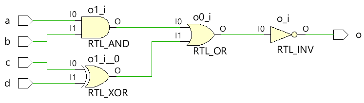
조합 게이트와 해당 Verilog 코드로 만든 다음 디지털 회로를 고려하십시오.
<노스크립트>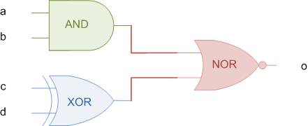
조합 논리에서는 값이 캡처되어 클록의 가장자리에 저장되는 플립 플롭과 같은 순차 요소와 달리 출력을 유지하기 위해 입력을 지속적으로 구동해야 합니다. 따라서 assign 오른쪽의 입력이 변경될 때마다 출력 o가 업데이트되기 때문에 문은 목적에 잘 맞습니다.
// This module takes four inputs and performs a boolean
// operation and assigns output to o. The combinational
// logic is realized using assign statement.

module combo (	input 	a, b, c, d,
								output  o);

  assign o = ~((a & b) | c ^ d);

endmodule
설계 정교화 및 합성 후에 우리는 assign에 의해 모델링된 것과 동일한 방식으로 동작하는 조합 회로를 보게 됩니다. 성명서.
RHS의 조합 식이 참이 될 때마다 신호 o가 1이 되는 것을 확인하십시오. 유사하게 o는 RHS가 거짓일 때 0이 됩니다. 같은 시간 동안 입력이 X이기 때문에 출력 o는 0ns에서 10ns까지 X입니다.
<노스크립트>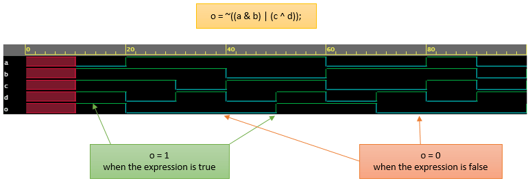
시뮬레이션 예제가 있는 슬라이드쇼를 보려면 여기를 클릭하십시오!
verilog
매개변수는 다른 사양으로 모듈을 재사용할 수 있도록 하는 Verilog 구성입니다. 예를 들어, 4비트 가산기는 비트 수에 대한 값을 허용하도록 매개변수화될 수 있으며 모듈 인스턴스화 중에 새 매개변수 값이 전달될 수 있습니다. 따라서 N비트 가산기는 4비트, 8비트 또는 16비트 가산기가 될 수 있습니다. 함수 호출 중에 전달되는 함수에 대한 인수와 같습니다. parameter MSB = 7; // MSB is a parameter with a constant value 7 paramet
Verilog는 하드웨어 설명 언어이며 설계자가 RTL 설계를 시뮬레이션하여 논리 게이트로 변환할 필요가 없습니다. 시뮬레이션이 필요한 이유는 무엇입니까? 시뮬레이션은 RTL 코드가 의도한 대로 동작하는지 확인하기 위해 다른 시간에 다른 입력 자극을 설계에 적용하는 기술입니다. 기본적으로 시뮬레이션은 설계의 견고성을 검증하기 위해 잘 따라야 하는 기술입니다. 또한 가공된 칩이 실제 세계에서 사용되는 방식과 다양한 입력에 반응하는 방식과 유사합니다. 예를 들어, 위의 디자인은 출력 pe 보여진 바와 같이. 시뮬레이션을 통해