

제조공정

산업 제조
 |
| × | 1 | |||
 |
| × | 1 | |||
| |
| × | 1 | |||
 |
| × | 1 | |||
| × | 1 | ||||
 |
| × | 1 | |||
| × | 1 | ||||
| |
| × | 1 | |||
 |
| × | 3 | |||
 |
| × | 3 | |||
 |
| × | 3 | |||
 |
| × | 1 | |||
 |
| × | 1 | |||
 |
| × | 1 |
 |
|
|
어렸을 때 나는 항상 생각으로 물건을 옮기거나 날아가는 것과 같은 특별한 능력을 갖고 싶었습니다. 나는 "내 마음의 힘"으로 물건을 움직이려고 시도했지만 물론 성공하지 못했습니다.글쎄, 나는 그랬고 나는 저는 Star Wars의 열렬한 팬이지만 전자 제품과 프로그래밍도 좋아합니다. 이 두 가지를 결합하여 놀라운 프로젝트를 만드는 것은 어떻습니까?
하드웨어 및 소프트웨어 섹션에서 링크가 있는 모든 부품, 코드 및 라이브러리를 찾을 수 있습니다.

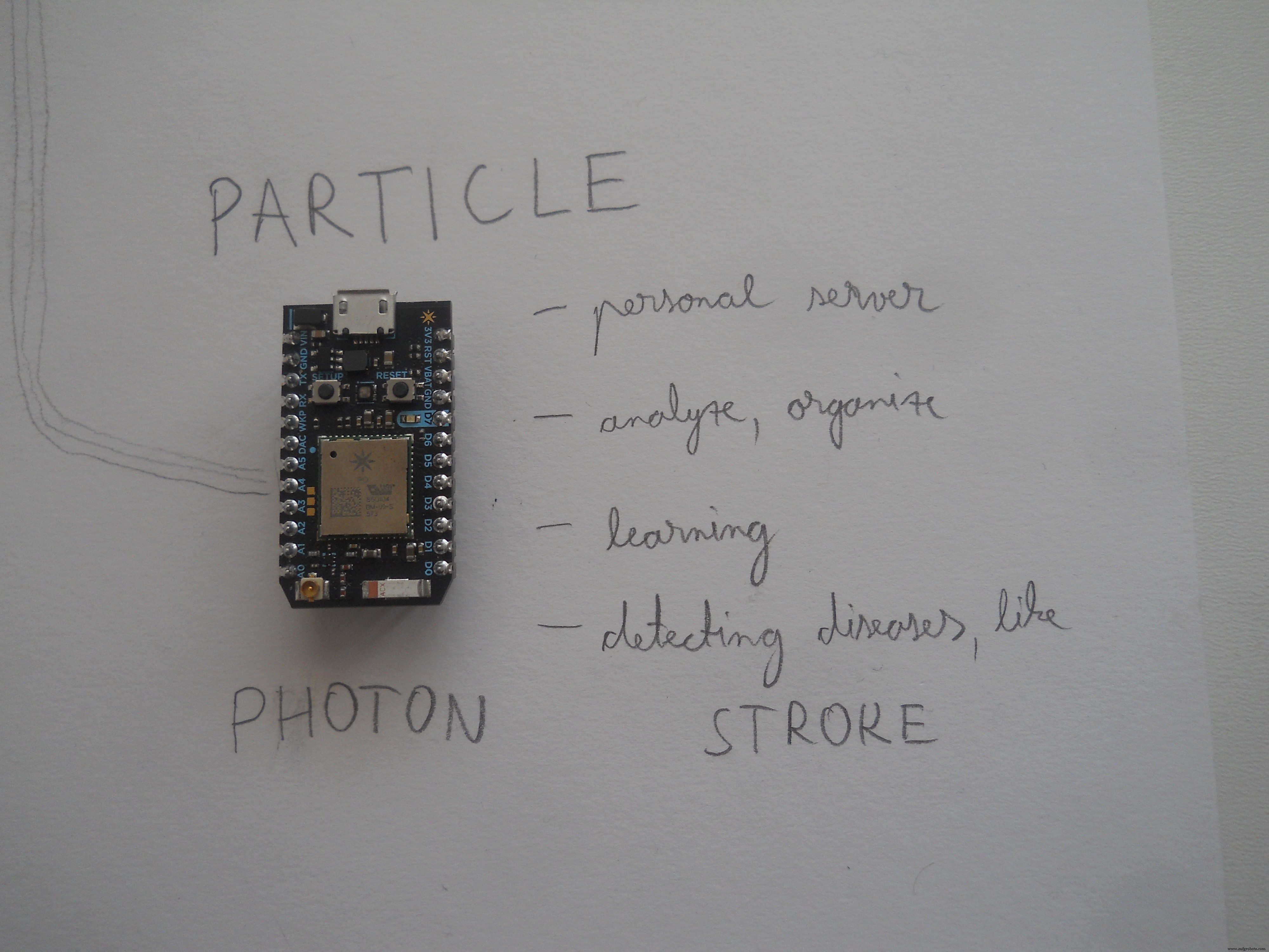
주요 개념 다른 뇌파를 사용하여 사용자가 로봇을 제어하거나 PC의 커서를 제어하거나 집에 있는 조명을 켜고 끌 수 있는 반면 마이크로컨트롤러(Particle Photon)는 사용자의 뇌파에 대한 온라인 분석을 생성합니다. 이것은 질병이나 스트레스 및 졸린 진술을 감지하는 완벽한 방법입니다. 이것은 또한 사람들이 더 나은 삶을 살도록 돕고 감정을 조절하고 항상 행복한 방법을 배우는 데 사용할 수 있습니다. 인간의 두뇌에는 균형이 필요합니다. 건강하려면 잠을 자고 생각하고 움직여야 합니다... Particle Photon과 Particle의 창립자가 만든 웹 서버를 사용하여 사람들이 자연스러운 두뇌 균형을 찾도록 도울 수 있습니다. 어린 시절의 꿈이 저를 이 프로젝트로 이끌었고, 제가 이 프로젝트를 하게 되어 매우 기쁩니다.
하지만 스타워즈와 포스를 잠시 접어두자면 이 장치는 게으른 사람이나 팬을 위한 것이 아니라 매일매일 장애를 안고 싸우는 사람들에게 능력을 되돌려주기 위해 만들어졌습니다. 내가 디자인한 로봇은 휠체어와 같은 방식으로 작동합니다. 홈 오토메이션 시스템은 사용자가 움직일 수 없어도 조명이나 TV를 제어하는 데 도움이 됩니다. PC 컨트롤러 모드는 완벽하게 건강한 사람에게도 유용할 수 있습니다. 우리 모두는 컴퓨터 게임을 하거나 생각만으로 인터넷 서핑을 하고 싶어합니다.
프로젝트 스토리에 대한 짧은 소개 동영상 보기:
나만의 것을 만들고 싶습니까? 여기에서 이 프로젝트에 대해 알아야 할 모든 것을 설명하겠습니다. 코드, 회로도 및 이 자세한 지침을 공유하므로 납땜 인두를 따뜻하게 하세요...
프로젝트 이면의 과학
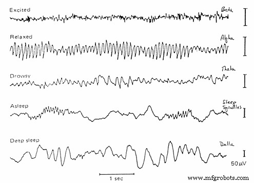
뇌파검사(EEG)는 뇌의 전기적 활동을 기록하는 전기생리학적 모니터링 방법입니다. 침습성 전극이 특정 응용 분야에서 때때로 사용되기는 하지만 일반적으로 두피를 따라 전극이 변위된 비침습성입니다. EEG는 뇌의 뉴런 내의 이온 전류로 인한 전압 변동을 측정합니다. 진단 애플리케이션은 일반적으로 EEG의 스펙트럼 콘텐츠, 즉 EEG 신호에서 관찰할 수 있는 신경 진동(일반적으로 '뇌파'라고 함) 유형에 초점을 맞춥니다. (Wikipedia 감사합니다) 하지만 우리는 두 개의 매우 정확한 값을 사용할 것입니다.
 <울>
<울>
어떻게 작동합니까?
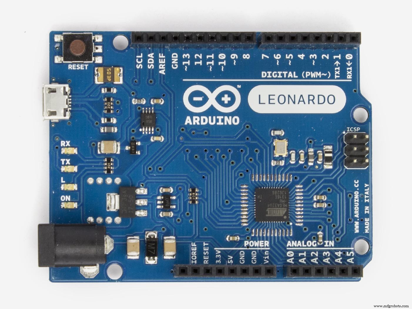
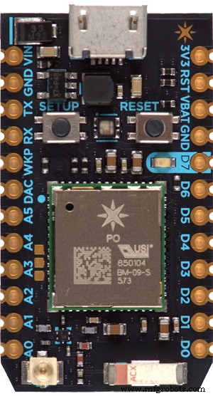
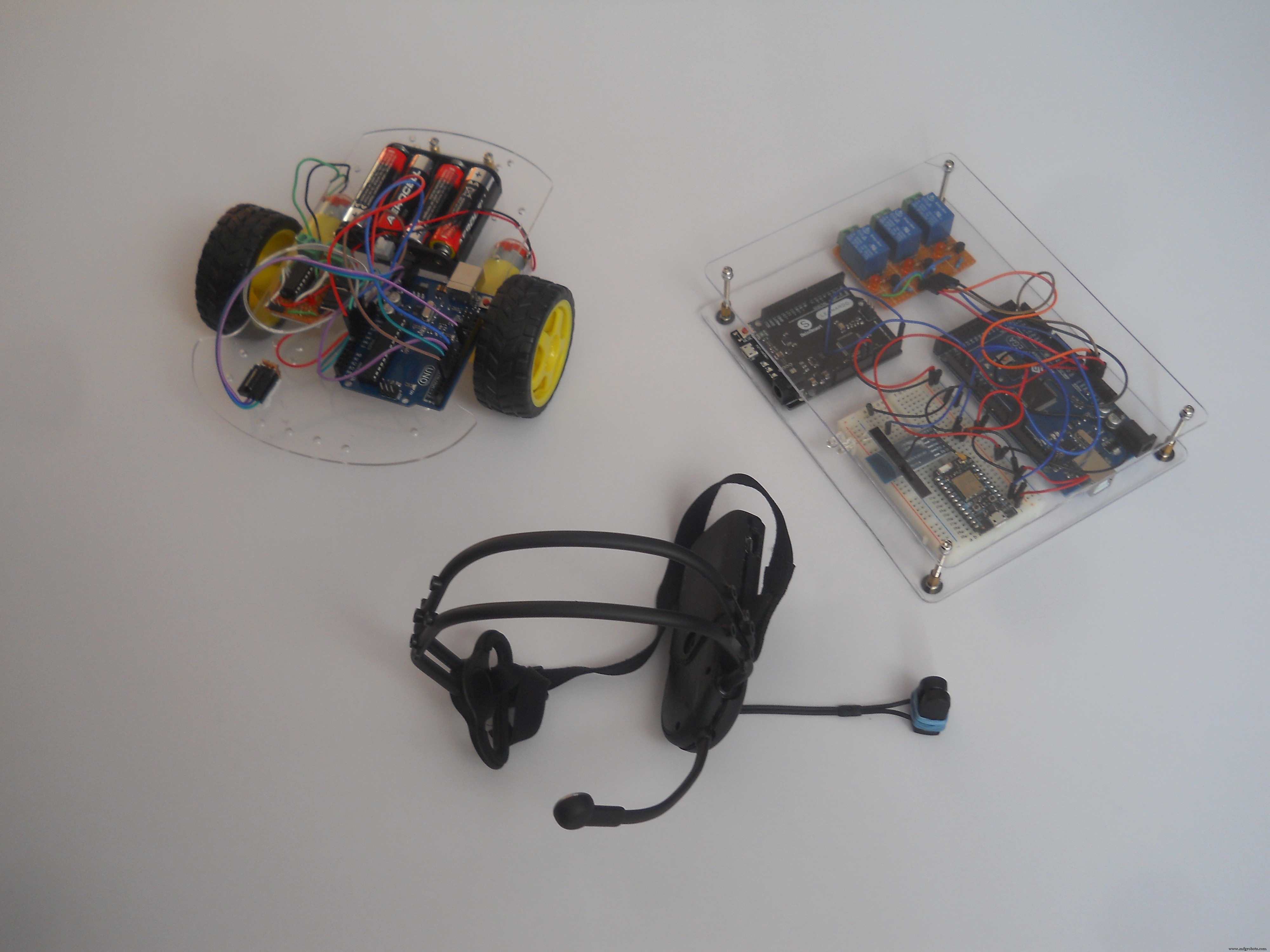
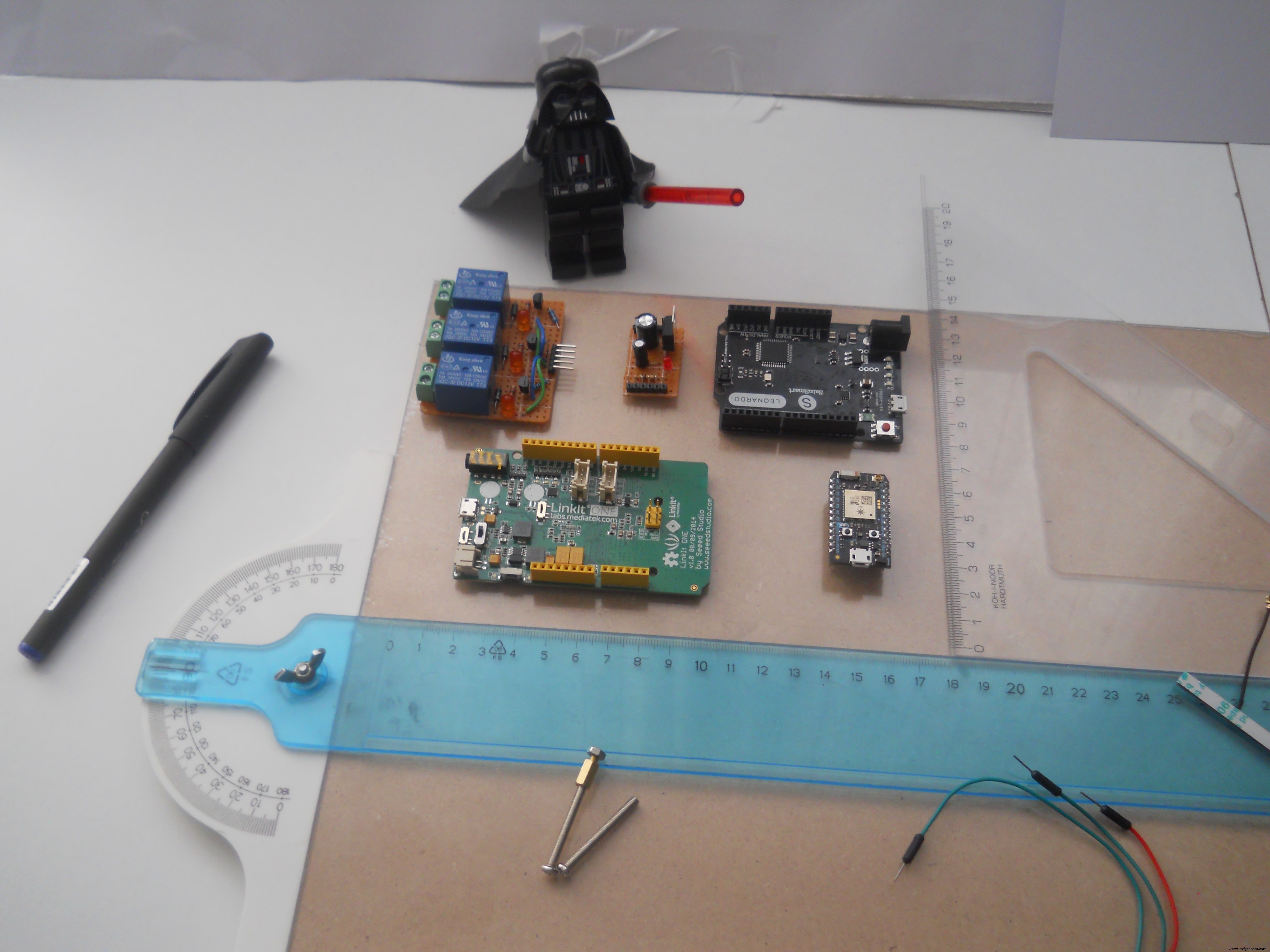
이 프로젝트에 생명을 불어넣기 위해 네 개의 마이크로컨트롤러를 사용했습니다:Arduino Mega, ArduinoLeonardo, UNO 및 Particle Photon. Mega는 헤드셋에서 신호를 수신하고 분석한 다음 명령을 다른 장치로 전달하는 프로젝트의 두뇌입니다. 웹서버를 생성하는 Photon으로 모든 데이터를 전송합니다. Leonardo는 PC에서 마우스를 제어하고 Uno는 IR(적외선 신호)을 수신하고 로봇을 제어하는 데 사용됩니다. 내가 말했듯이 장치는 세 가지 다른 것을 제어할 수 있습니다(또는 다른 것을 프로그래밍하려는 경우 그 이상). 이제 이 세 가지를 채널이라고 부를 것입니다. 눈을 감으면 장치가 다음 채널 사이를 전환합니다.
<울>릴레이를 사용하여 TV, 전구, 벽면 콘센트 등 원하는 모든 것을 연결할 수 있는 홈 오토메이션 기능을 만들었습니다.
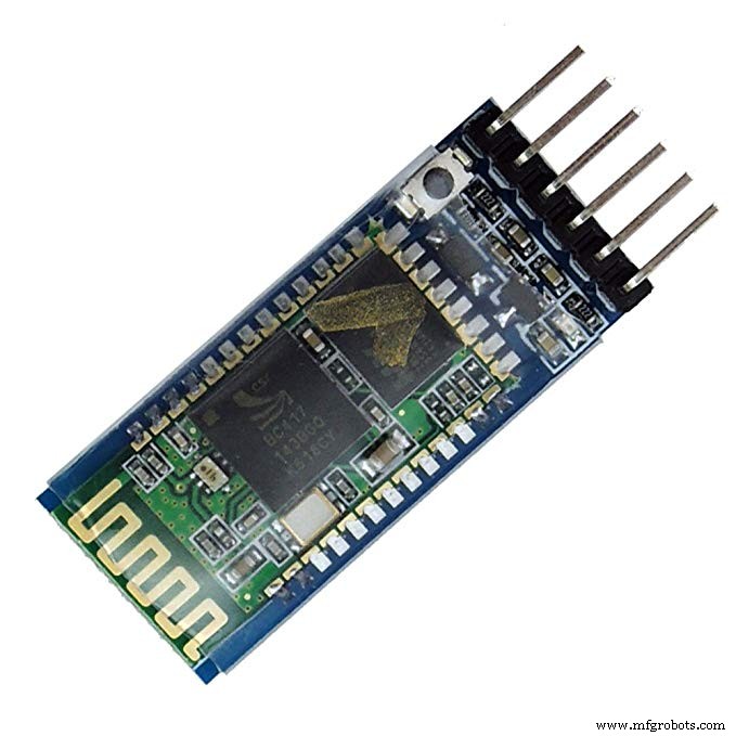
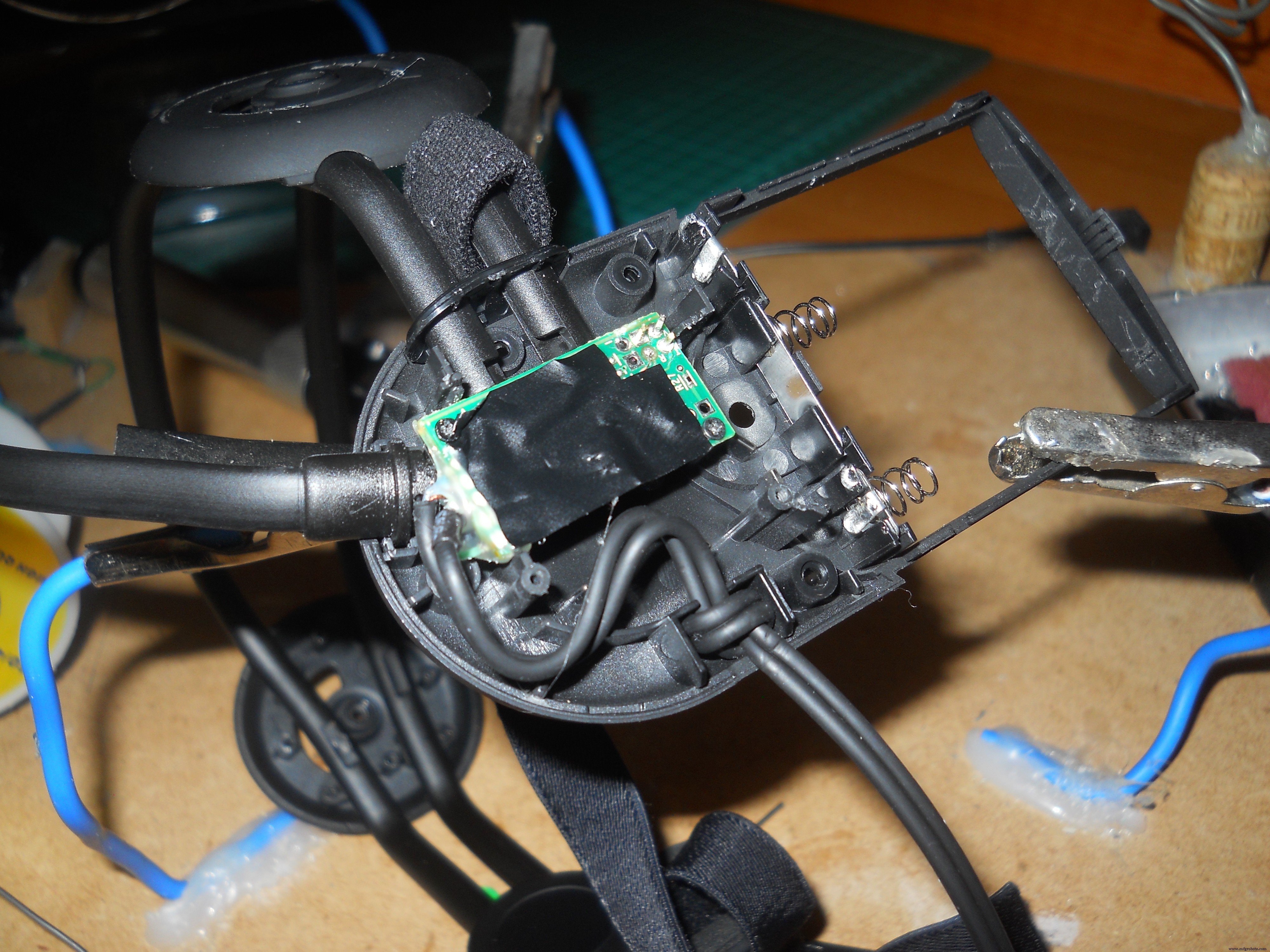
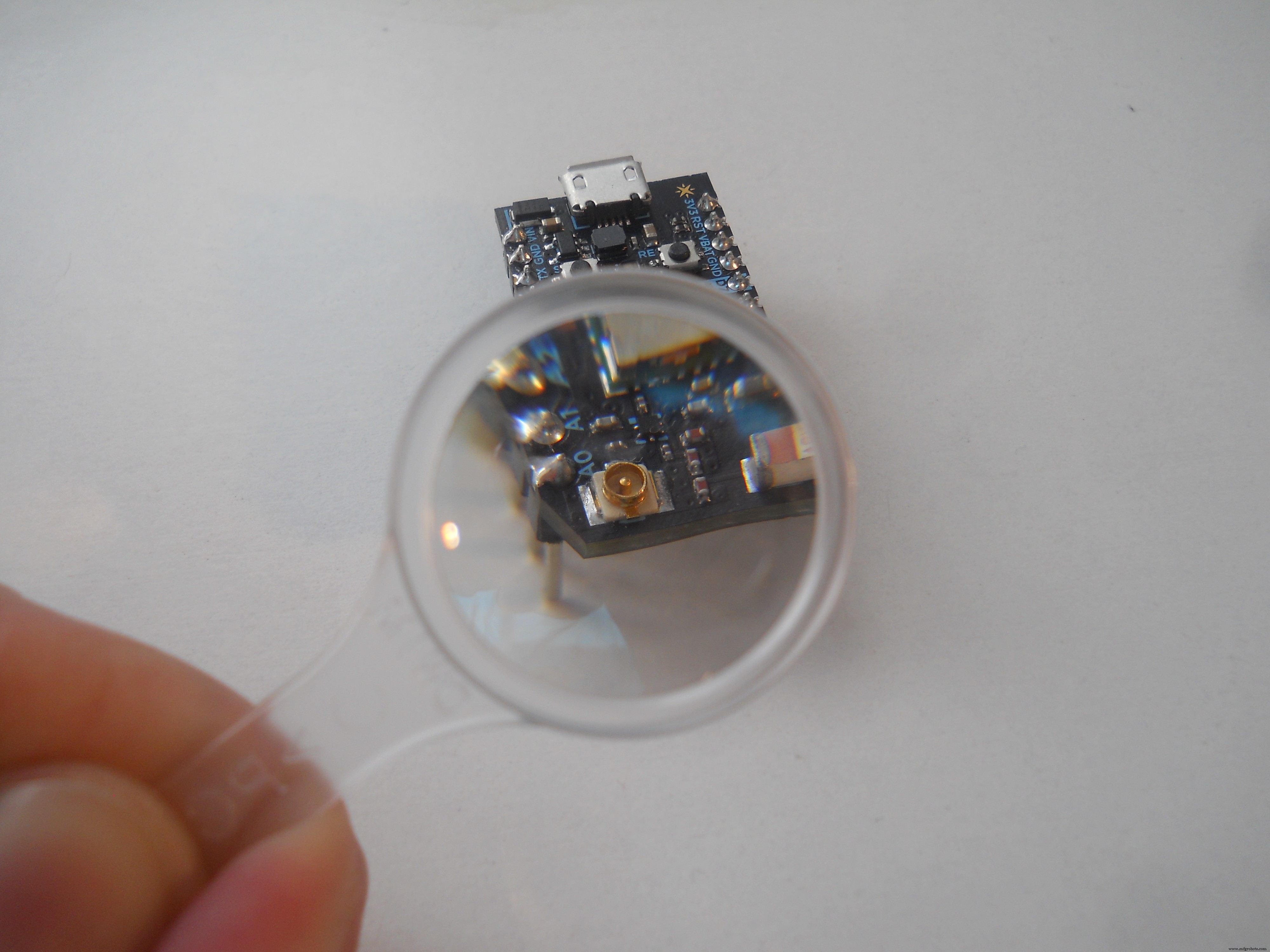
무선 헤드셋:
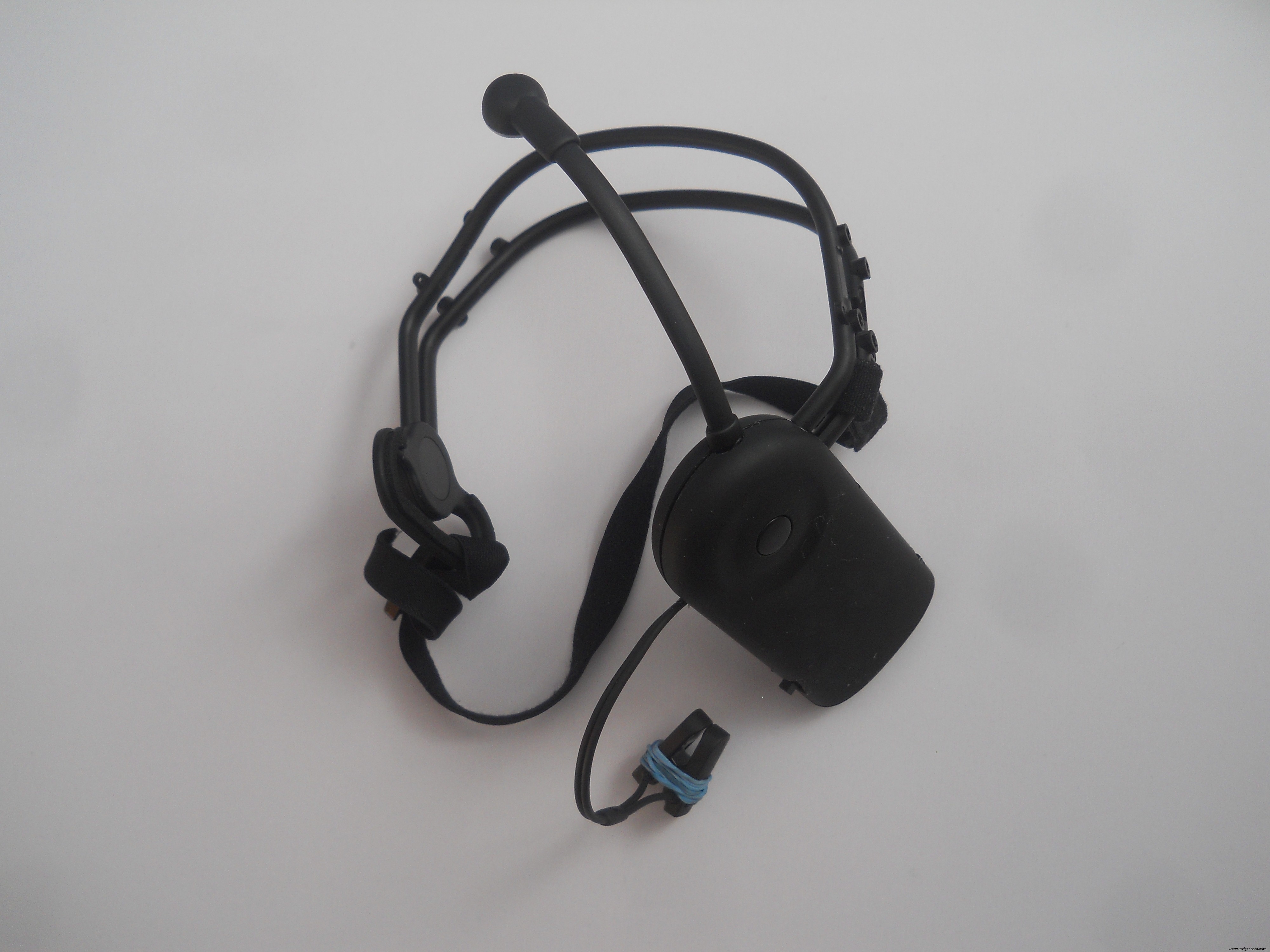
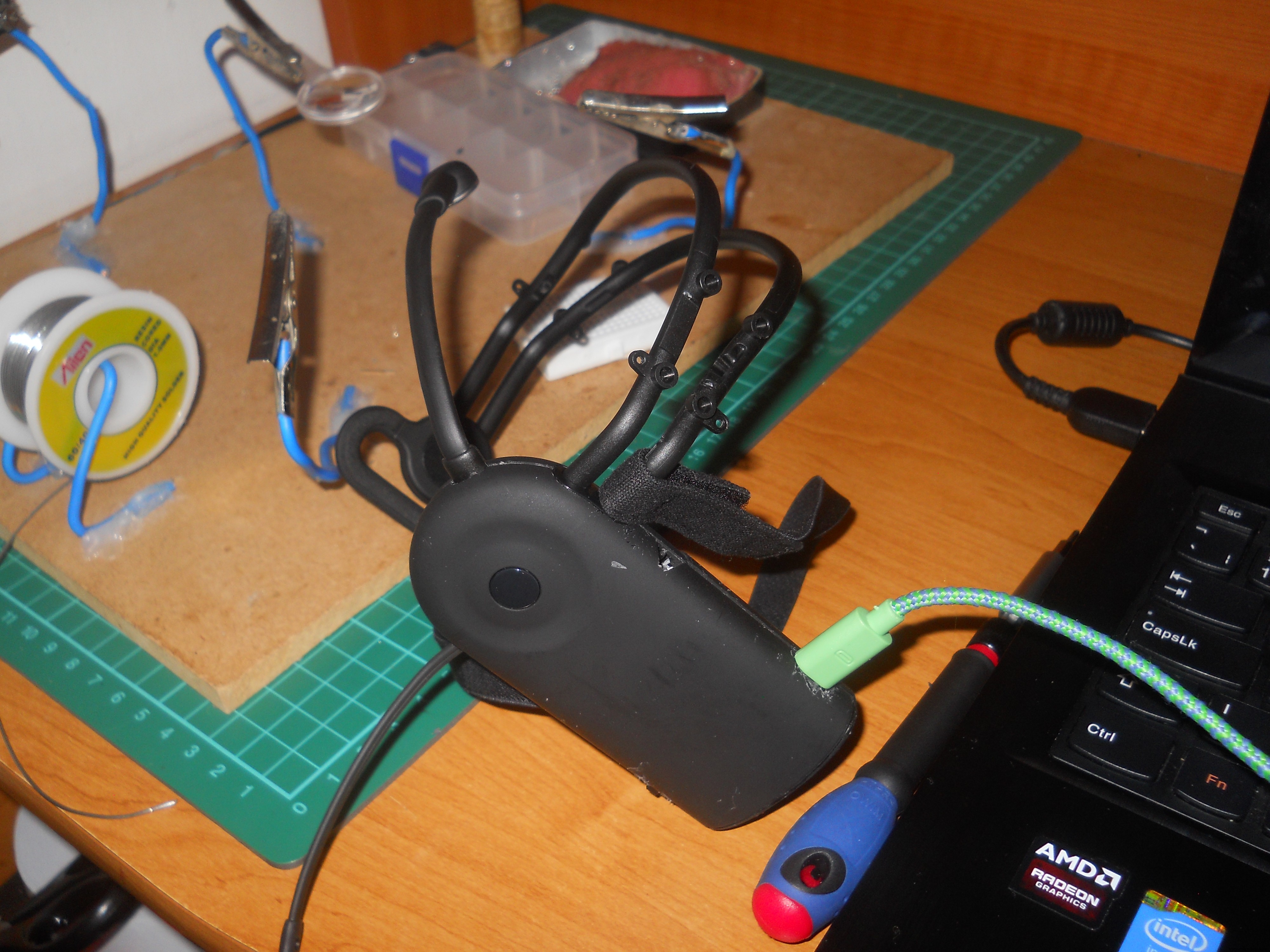
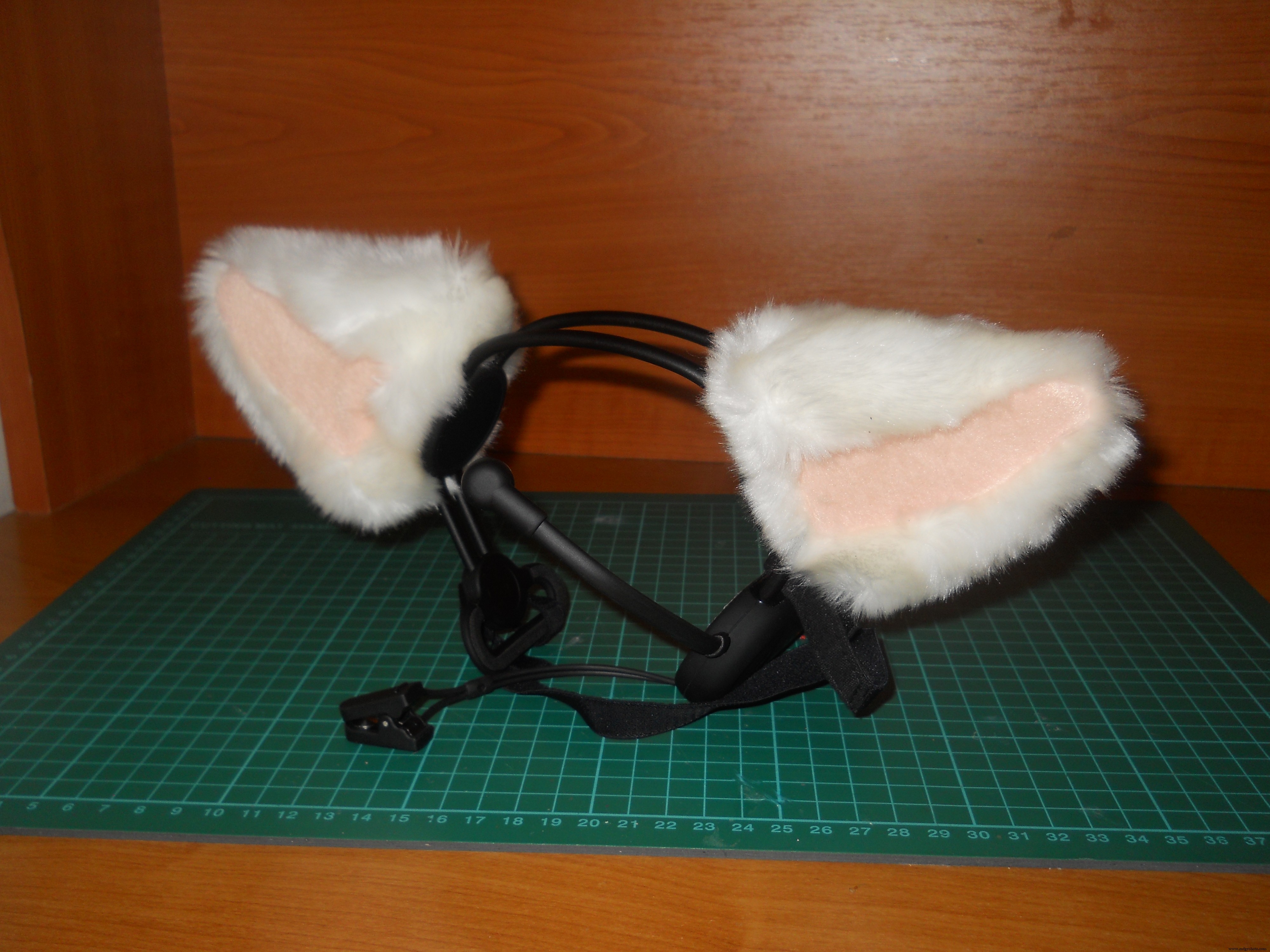
저는 해킹토이를 좋아해서 뇌파(주의, 명상)에 따라 귀가 움직이는 뇌파 감지 장난감 네코미미를 샀습니다. 이것은 내가 본 것 중 가장 쓸모없는 장난감이지만 뇌파를 읽고 노이즈를 걸러내고 매우 좋은 신호를 제공하는 작은 칩이 내부에 있습니다. UART(Serial) 인터페이스와 함께 작동하므로 일부 해킹으로 Arduinos를 사용하여 뇌파를 읽을 수 있습니다. 이 헤드셋의 역할은 무선으로 뇌파를 중앙 서버로 전송하는 것입니다. 아무도 머리에 케이블을 꽂고 싶어하지 않기 때문에 이 편안하고 사용자 친화적인 헤드셋을 만들었습니다.
무선 블루투스 헤드셋을 분해하고 만드는 방법을 보려면 아래로 이동하세요.
어떻게 사용하나요?
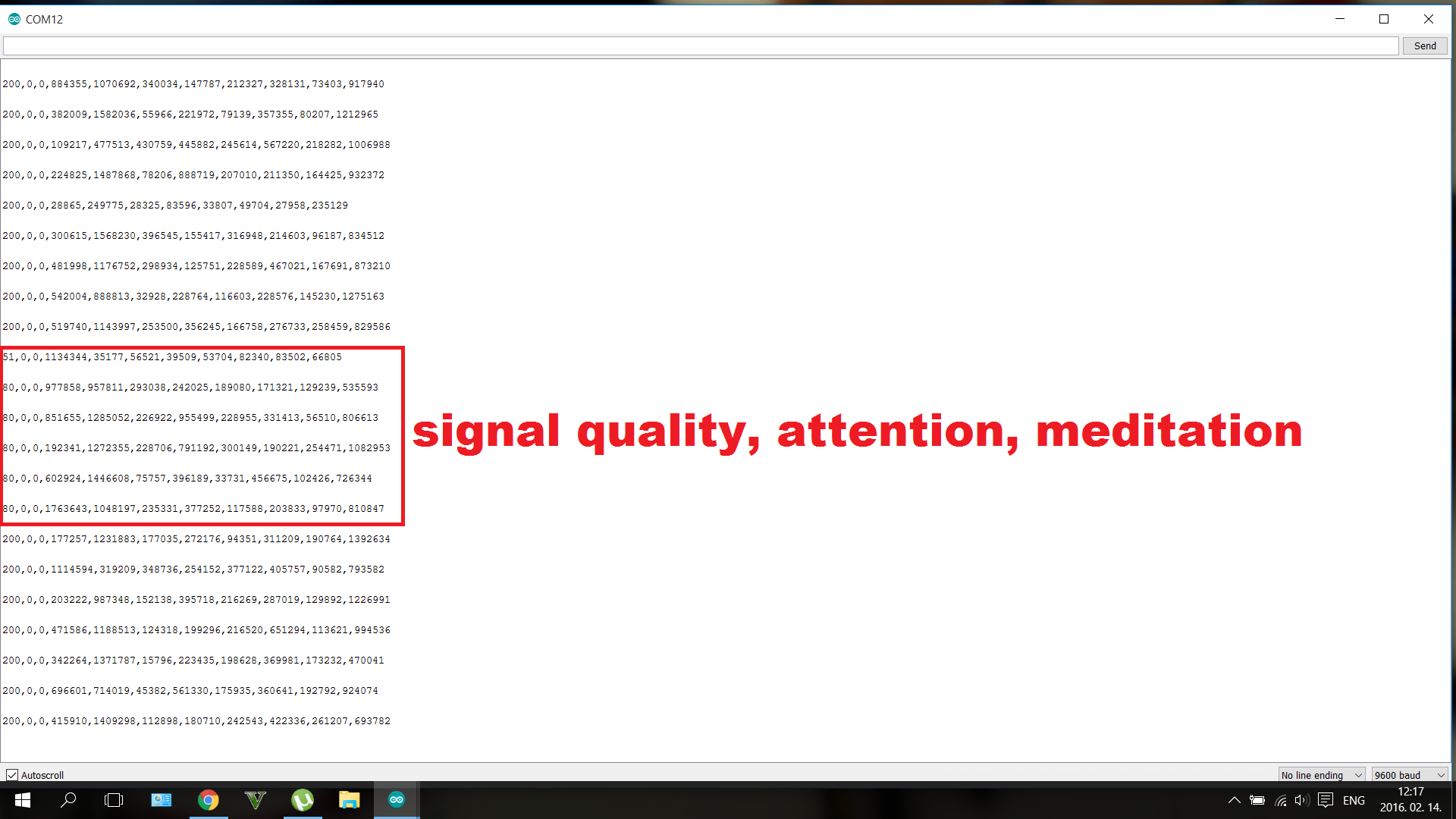
측정 가능한 eSense 값(NeuroSky 값)에는 0에서 100까지의 명상과 0에서 100까지의 주의가 있습니다. 집중할수록 주의 값이 높아집니다. 긴장을 풀수록 명상 수준이 높아집니다.
시스템은 생각과 함께 작동하며 집중하거나 이완하는 방법만 배울 필요가 없습니다. 일주일간의 실험 후에 나는 나의 "주의" 값을 매우 정확하게 제어할 수 있었습니다. 의식적으로 주의 수준을 약 15, 39, 65, 90으로 설정할 수 있습니다. 자신의 가치를 제어하는 방법을 찾아야 합니다. 우리는 모두 다릅니다. 감정과 아주 잘 어울렸다. 사랑, 우정, 분노 또는 두려움에 대해 생각하면 가치관이 매우 잘 대조됩니다.
시스템의 전원을 켜려면 마이크로 USB를 연결하세요. Arduino Leonardo의 케이블. 이것은 또한 (원하는 경우) 마우스를 제어하고 시스템에 대해 5볼트 및 500mA를 보장합니다.
홈 자동화 시스템 제어
홈 오토메이션 모드로 전환된 경우 주의 수준을 70 이상으로 높여 첫 번째 릴레이를 켜세요. , 명상 레벨을 70 이상으로 높여 두 번째 릴레이를 켭니다. , 그리고 세 번째 릴레이를 켜려면 둘 다 70 이상으로 증가 . 약간 까다롭지만 몇 가지 마인드 트레이닝 후에는 불가능하지 않습니다. 가 이미 켜져 있는 경우 동일한 명령을 사용하여 끄십시오(따라서 가 켜져 있으면 70에 다시 도달하여 끄십시오). 시스템이 완료되면 모든 고전압 장치(조명, TV, PC, 쿨러 팬, 원하는 모든 것)를 릴레이 모듈에 연결할 수 있습니다.
마우스 제어
커서는 감정으로 제어됩니다. 주의 수준이 25단계 미만인 경우 , 25와 50 사이의 경우 오른쪽으로 이동 , 50에서 75 사이인 경우 위로 이동 75에서 100 사이이면 아래로 이동 . 명상 레벨을 높여 클릭할 수 있습니다. 앞서 말했듯이 주의력은 감정으로 쉽게 조절할 수 있습니다(저에게는).
로봇 제어
로봇에는 정지, 좌회전, 전진의 세 가지 명령만 있습니다. 이동 옵션이 두 개뿐인 이유는 무엇입니까? 이 두 방향만 있으면 로봇을 원하는 곳 어디든지 움직일 수 있기 때문입니다. 명상 레벨을 사용하여 회전 로봇과 함께 이동하고 싶은 방향에 도달하면 로봇을 멈추고 주의 수준으로 앞으로 이동합니다. . 로봇을 제어하는 데 더 좋은 방법이며 주의력/명상 값을 잘 제어하지 못하는 초보자도 이 로봇을 가지고 놀 수 있습니다.
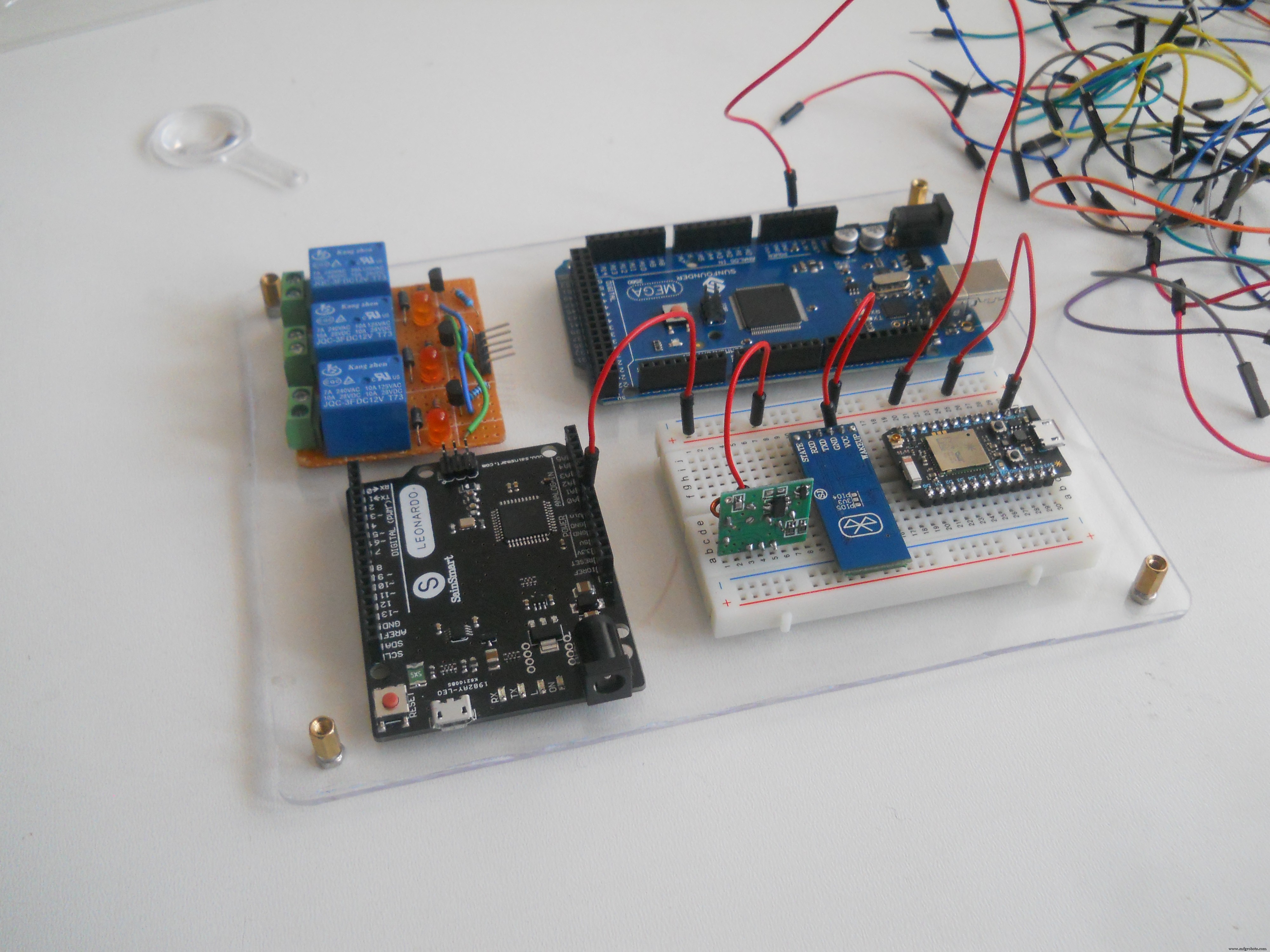
내 계획
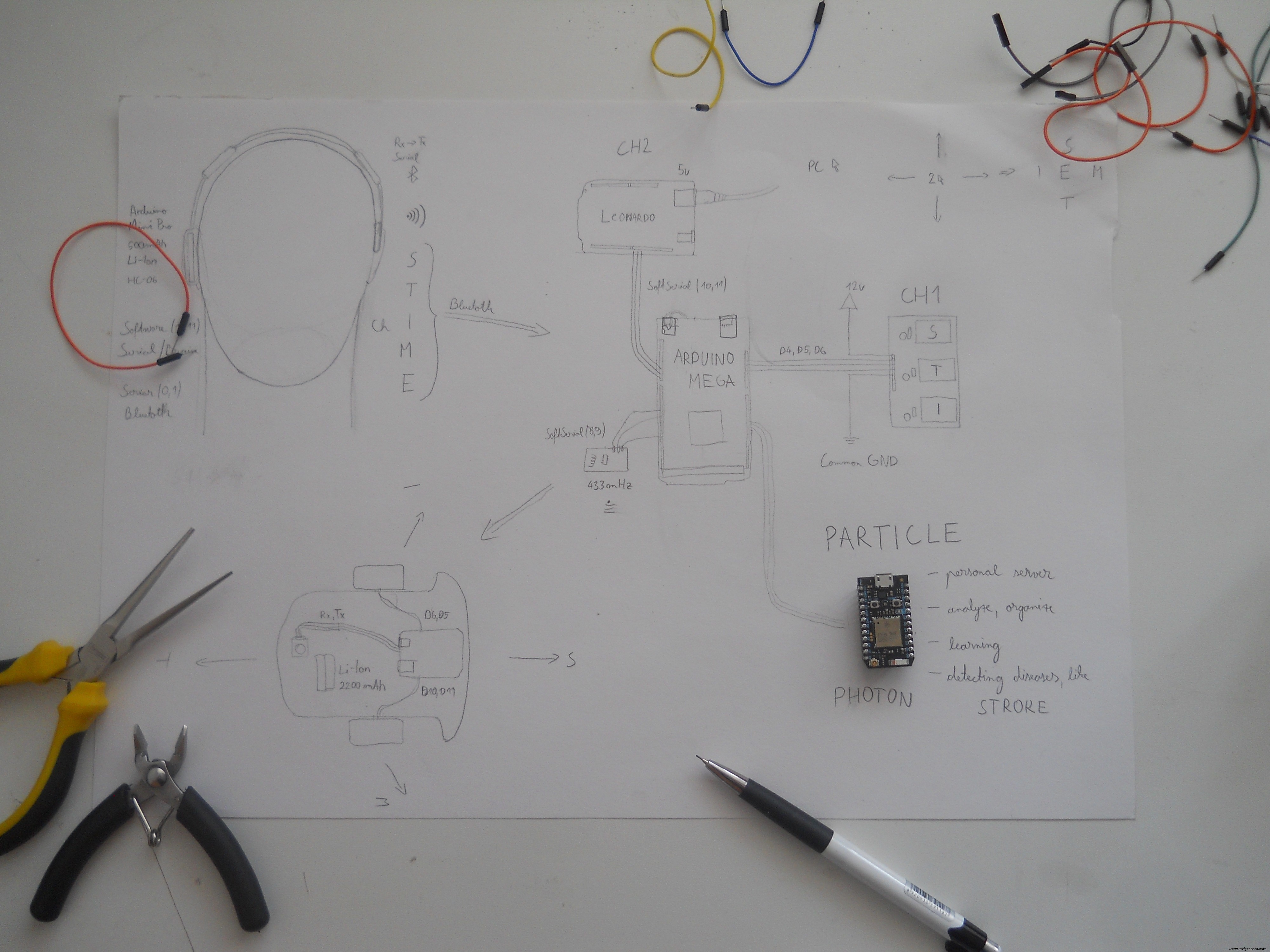
이것은 내 계획에 대한 더 오래된 그림이지만 성공했습니다.그래서 결과에 매우 만족합니다. 헤드셋은 BT(Bluetooth) 신호를 전송합니다. 들어오는 바이트를 분석하고 사용자의 생각에 따라 다른 기능을 제어하는 Arduino Mega에. 이 많은 데이터를 전송하는 가장 좋은 방법을 찾는 것이 매우 어려웠지만 Wi-Fi 대신 Bluetooth를 선택했습니다. 처음에는 Particle Photon을 데이터 전송기로 사용하고 싶었지만 그 작은 녀석이 웹 서버를 만드는 데 더 나은 역할을 하게 되었습니다. 전체 프로젝트에서 가장 큰 수정 사항이었습니다. (사진에서 실제 계획을 볼 수 있습니다). 집에서 만든 Arduino 모듈을 사용했습니다 , 왜냐하면 나는 내 자신의 회로를 디자인하는 것을 좋아하기 때문입니다. 원하는 경우 이 모듈을 온라인으로 구입하거나 저와 함께 구축할 수 있습니다.
반년 간의 학습 및 실험
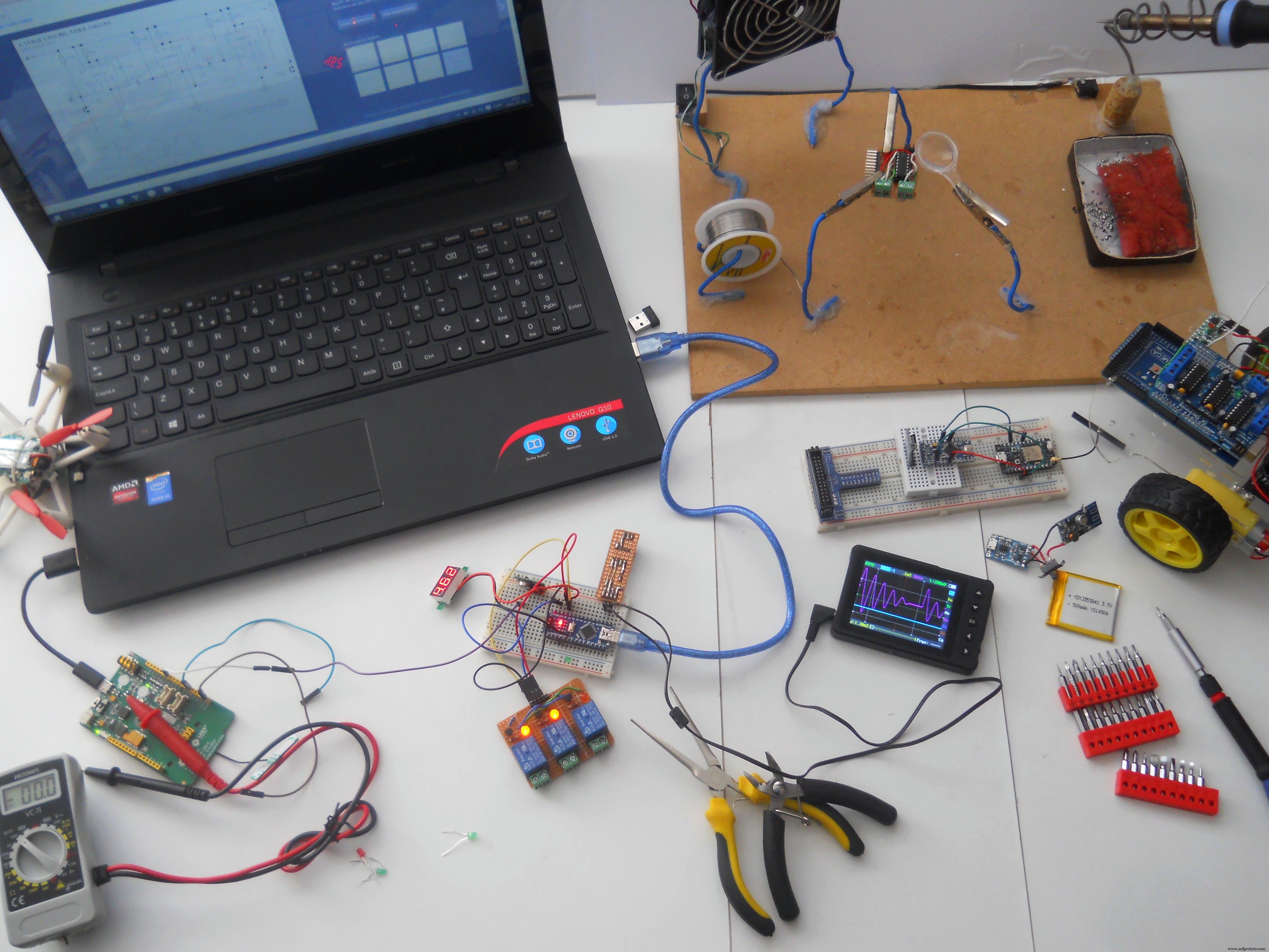
저는 이 프로젝트에서 많은 일을 했습니다. 예, 거의 반년 전에 시작했지만 Photon으로 일이 가속화되었습니다. 대시보드를 사용하는 것은 매우 쉬웠습니다. 그건 그렇고 인터넷에 EEG 장난감을 해킹하는 방법에 대한 많은 자습서가 있습니다. 약간 도움이되었지만 추가 기능이 없었습니다. 그래서 나는 이 Necomimi 장난감을 해킹하기로 결정하고 내 창의력을 사용하여 LED를 깜박이는 것보다 훨씬 더 많은 기능을 가진 이 장치를 만들었습니다. 즐기시기 바랍니다!
시작하겠습니다!
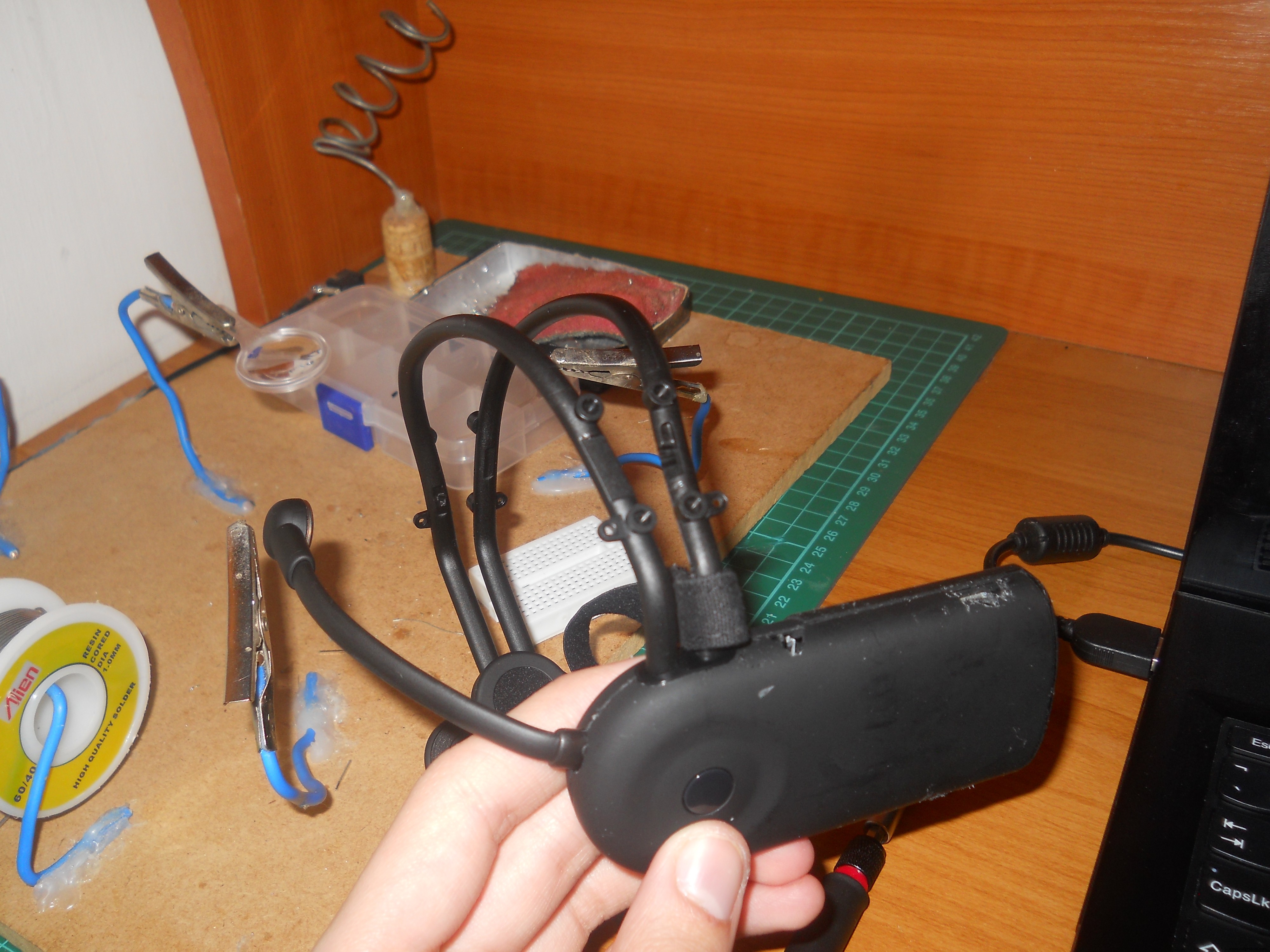
네코미미 장난감 해킹하기
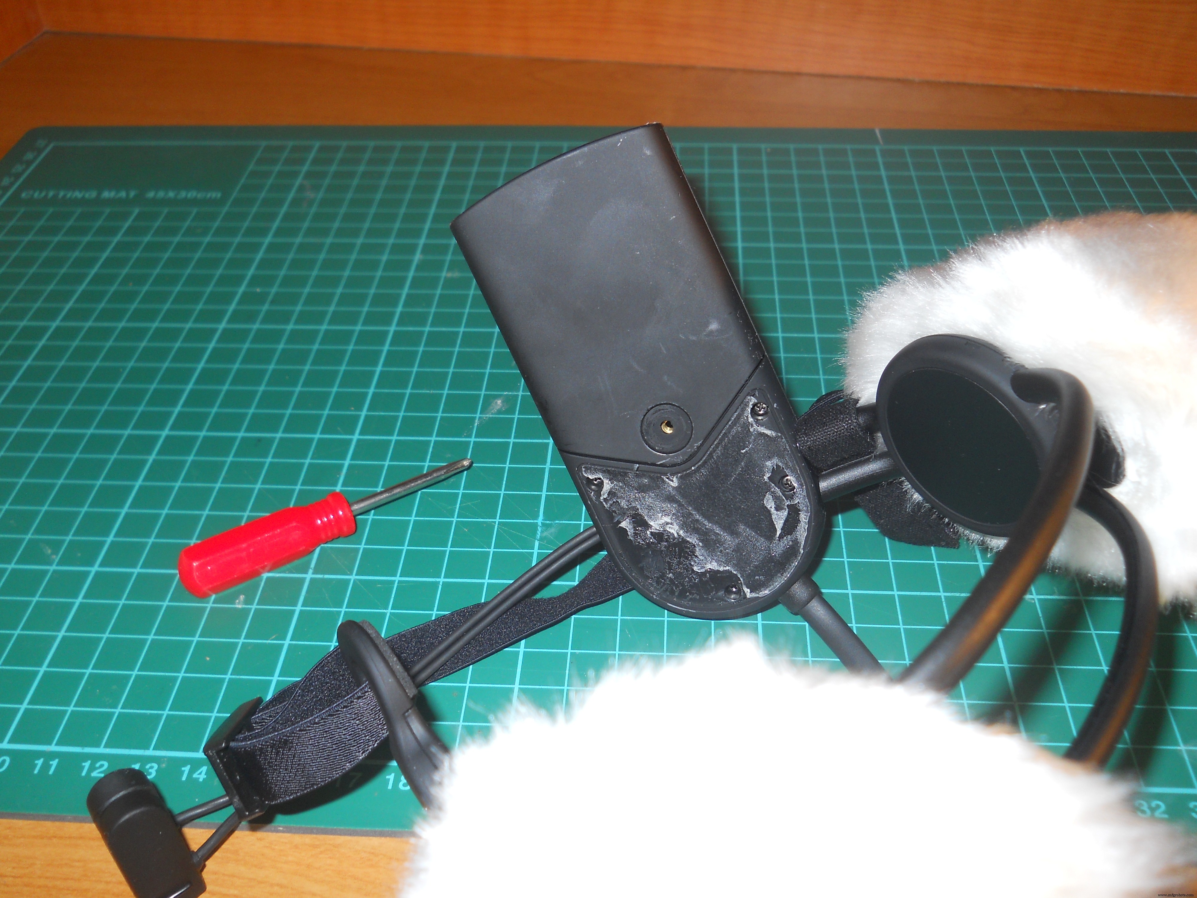
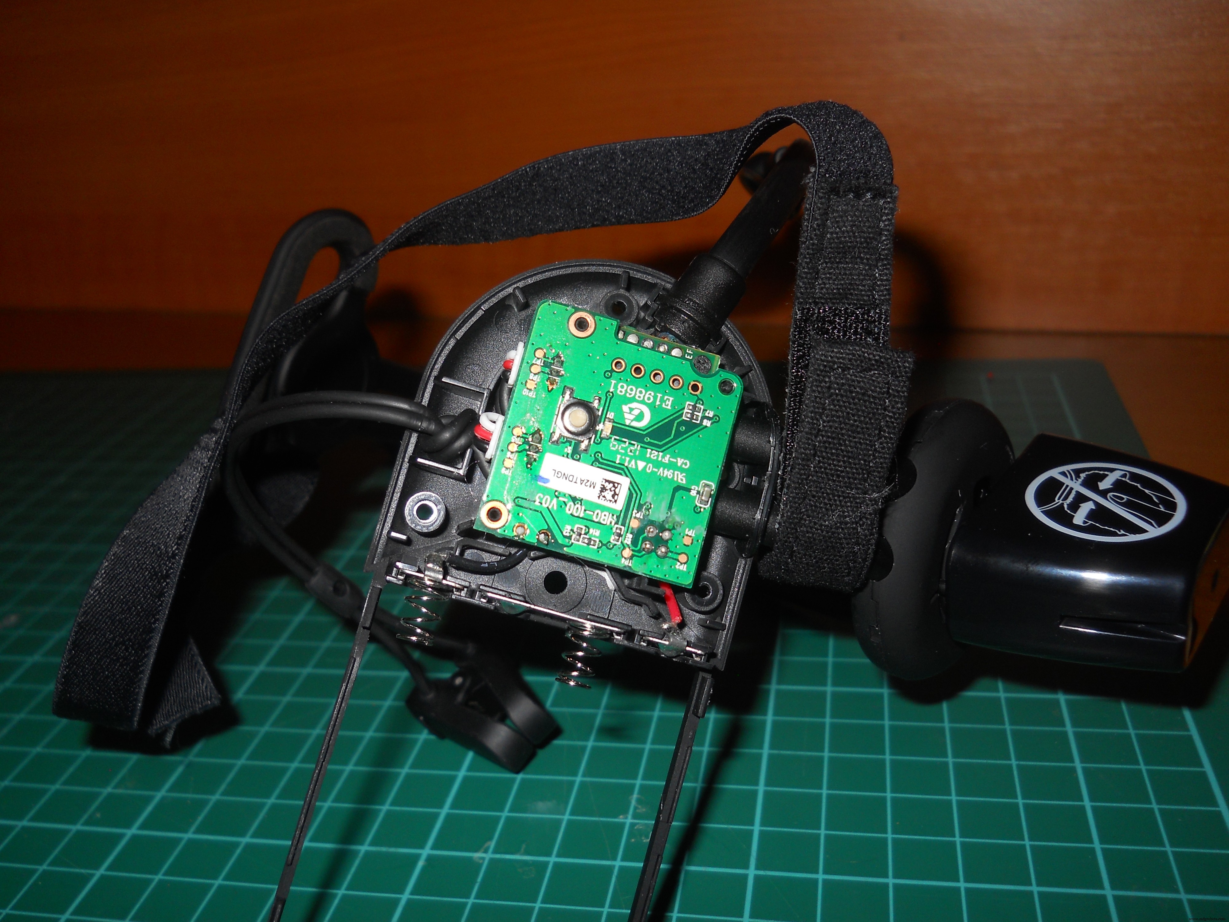
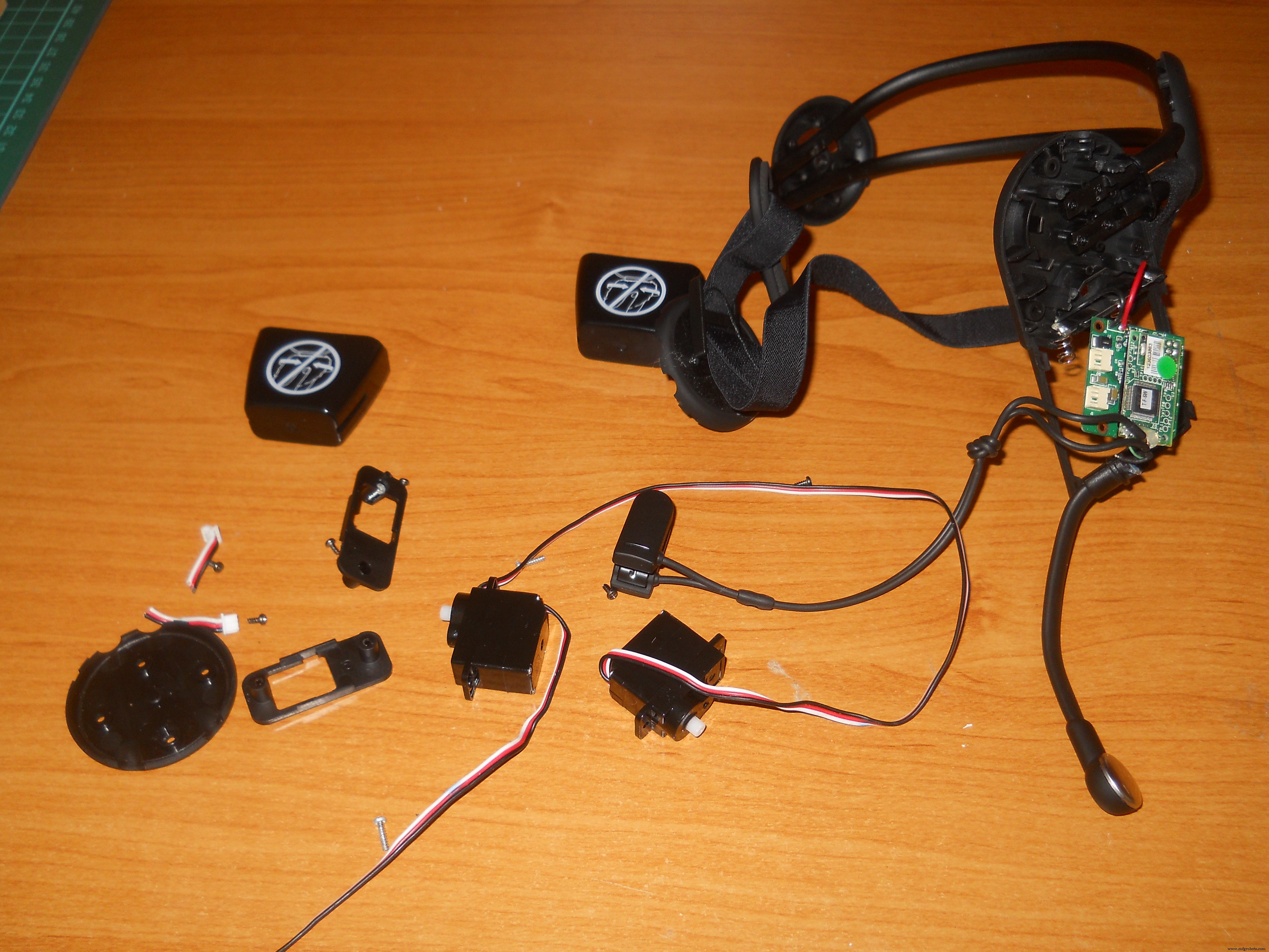
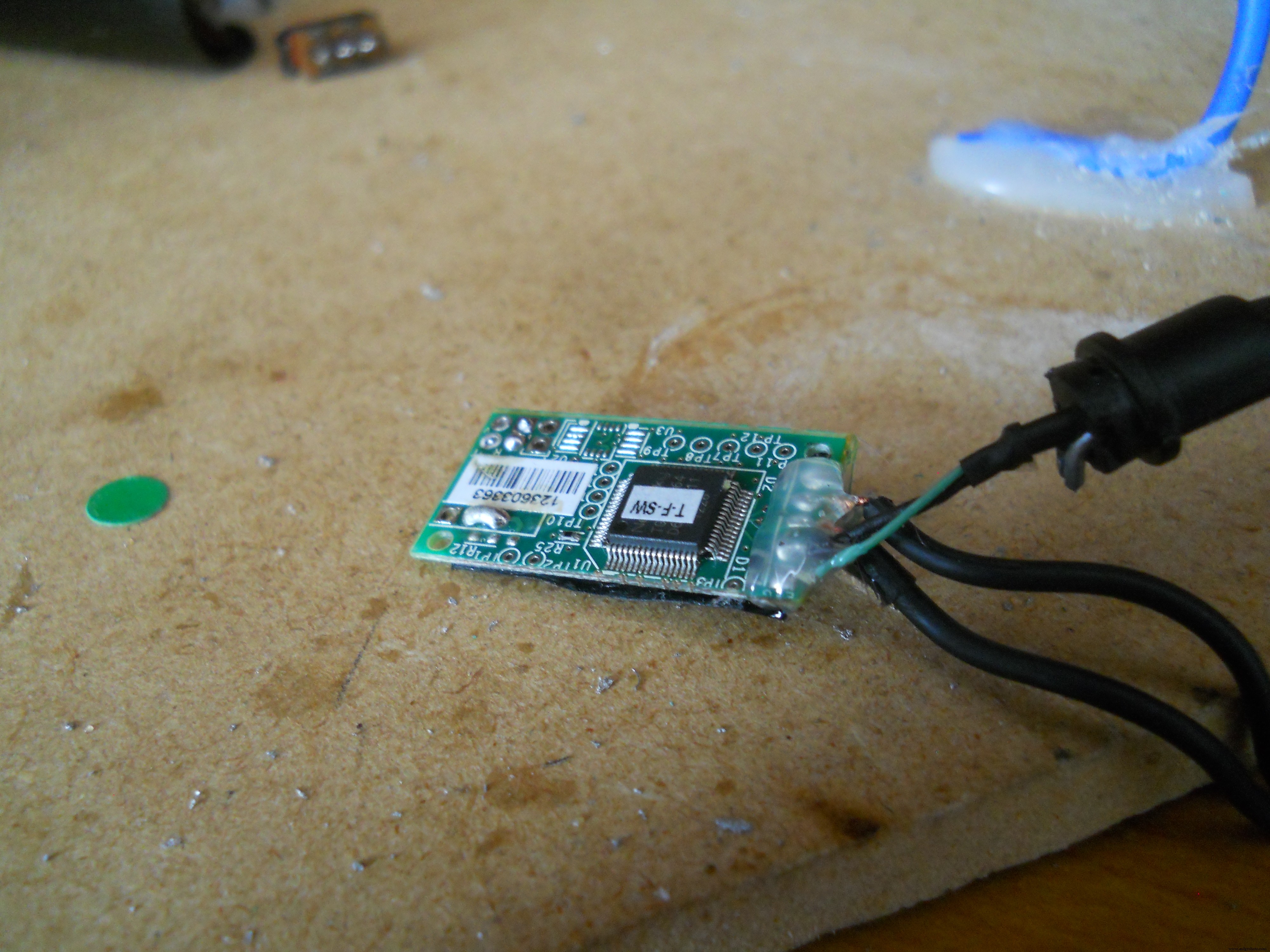
블루투스를 통해 데이터를 전송하도록 이 EEG 장난감을 수정하고 싶으므로 먼저 케이스를 분해하십시오. 나사는 스티커 아래에 있습니다.스티커 제거 및 뒷면 장치의 내부에서 찾을 수 있습니다. 주 회로 아래에 있는 것은 Neurosky TGAM 칩입니다. 이것은 메인 마이크로컨트롤러 보드에 4개의 헤더 핀으로 연결되어 있으므로 납땜 인두를 가지고 이 회로를 제거하십시오 주의하여. 이제 세 개의 와이어를 GND 핀에 VCC 핀과 T 핀에 납땜합니다. T-핀은 전송 속도가 57600인 전송기 핀입니다. 이것은 데이터 패킷을 마이크로컨트롤러로 전송하지만 이를 HC-06 slaveBT 모듈에 직접 연결했습니다 . HC-06은 9600 보드 레이트로 설정되어 있지만 이 문제는 해결될 테니 걱정하지 마세요. 세 개의 전선을 납땜하면 자체 충전식 전원을 구축할 수 있습니다. 500mAh 리튬 이온 배터리, USB 충전기 회로, 5v 스텝 업 회로 및 2개의 저항(100옴 및 200옴)을 사용하여 칩과 Bluetooth 모듈에 완벽한 3.4볼트 전원 공급을 보장합니다. 회로도를 따라 빌드하십시오. 헤드셋에 필요한 회로. 회로가 완료되면 Bluetooth 모듈을 구성합니다.
칩 정보:
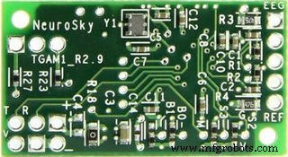
Neurosky ThinkGear AM은 직렬 인터페이스를 통해 데이터를 필터링, 증폭 및 전송하도록 설계되었습니다. 자세한 정보는 여기를 참조하세요.
회로도 / 전자 장치
아래 지침과 그림에 따라 나만의 무선 EEG 헤드셋을 만드세요.

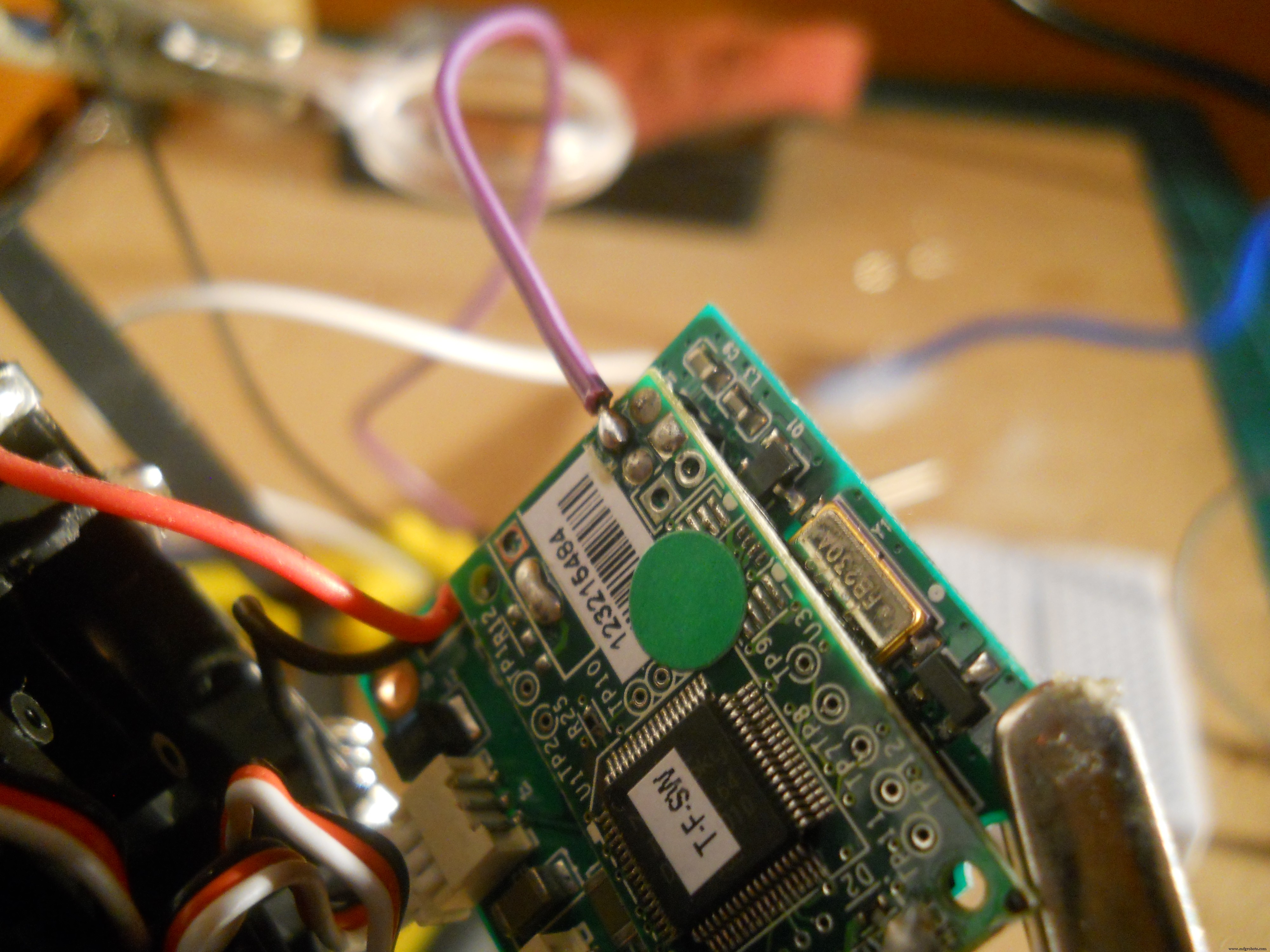
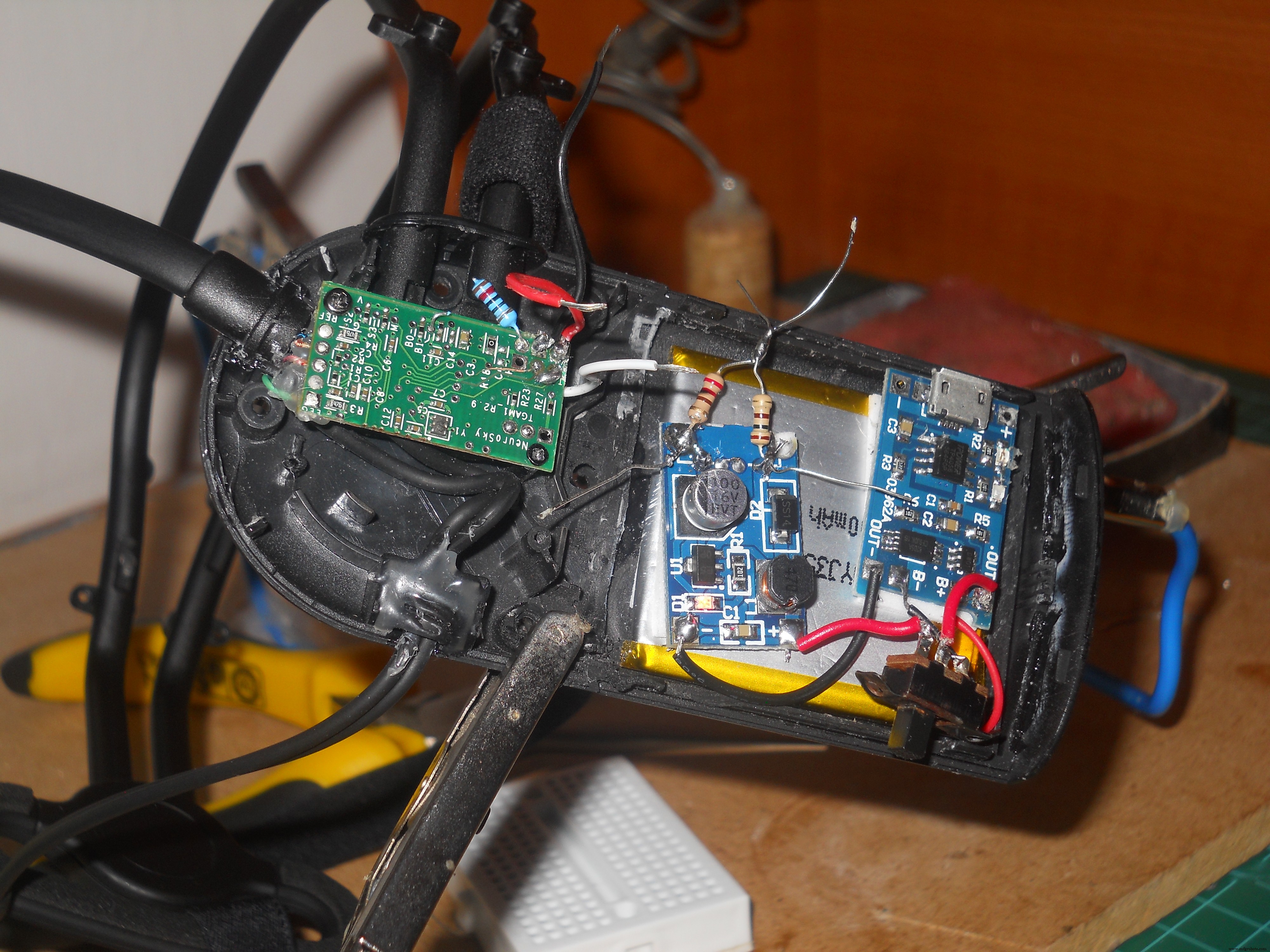
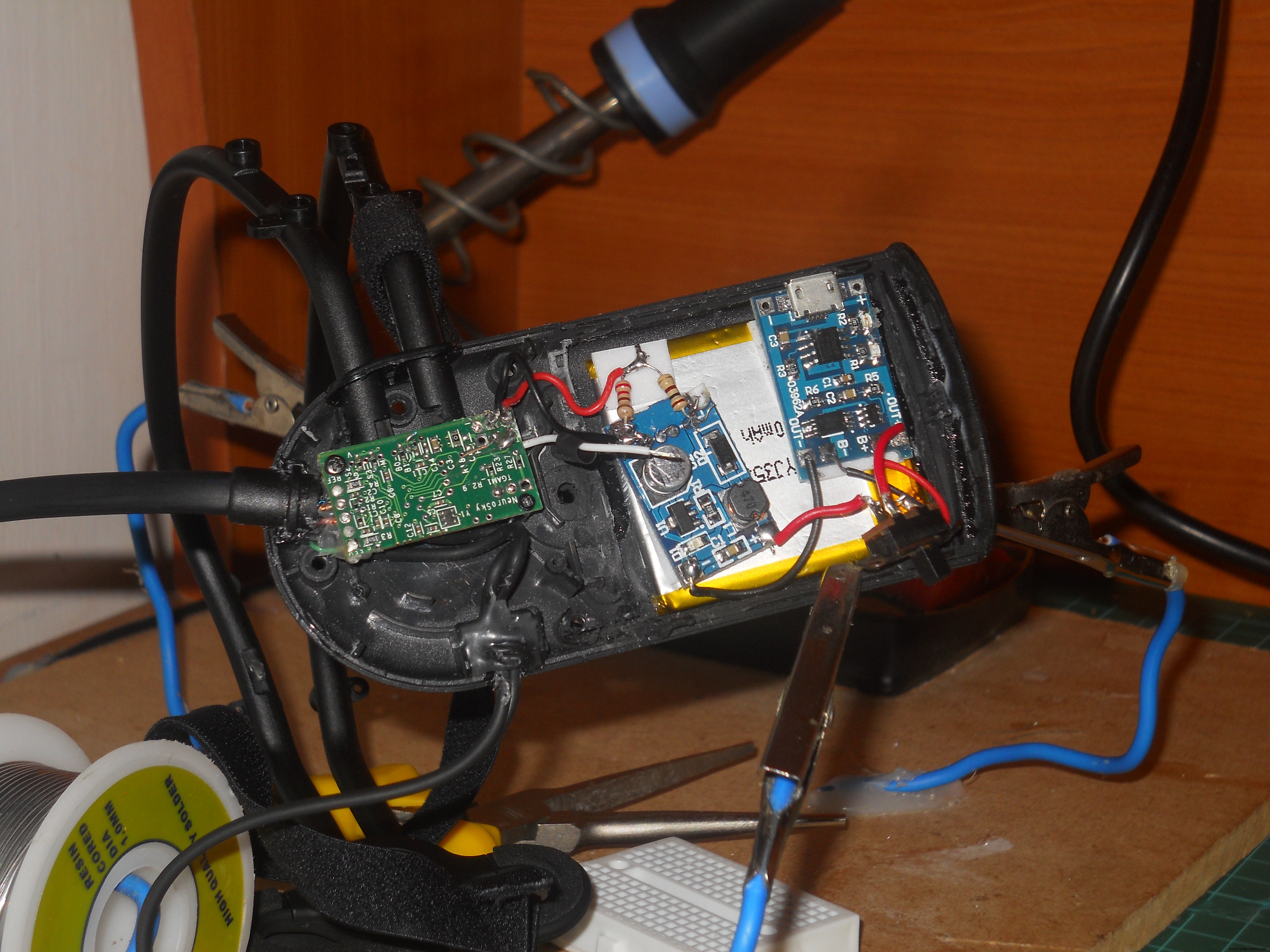

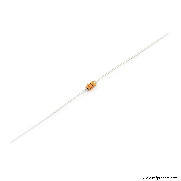
안정적인 전압을 생성하려면 500mAh 리튬 이온 배터리, 5v 전압 스텝업 모듈이 필요하고 안정적인 3.3볼트로 전압을 낮추기 위해 100옴 및 200옴 저항이 필요합니다. 전원을 켜고 블루투스 모듈에 데이터를 전송하기 위해 암 헤더 핀을 납땜했습니다.
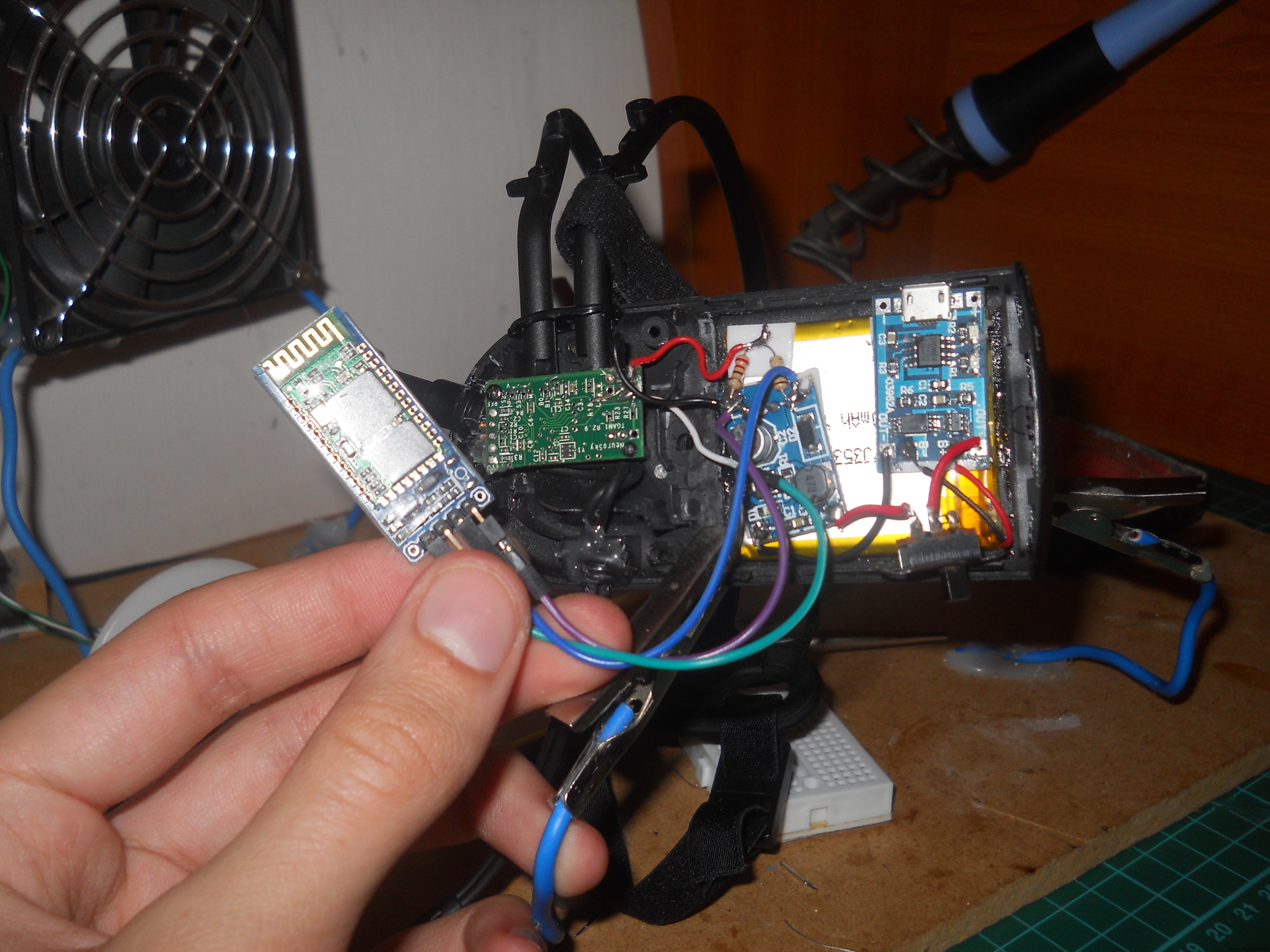
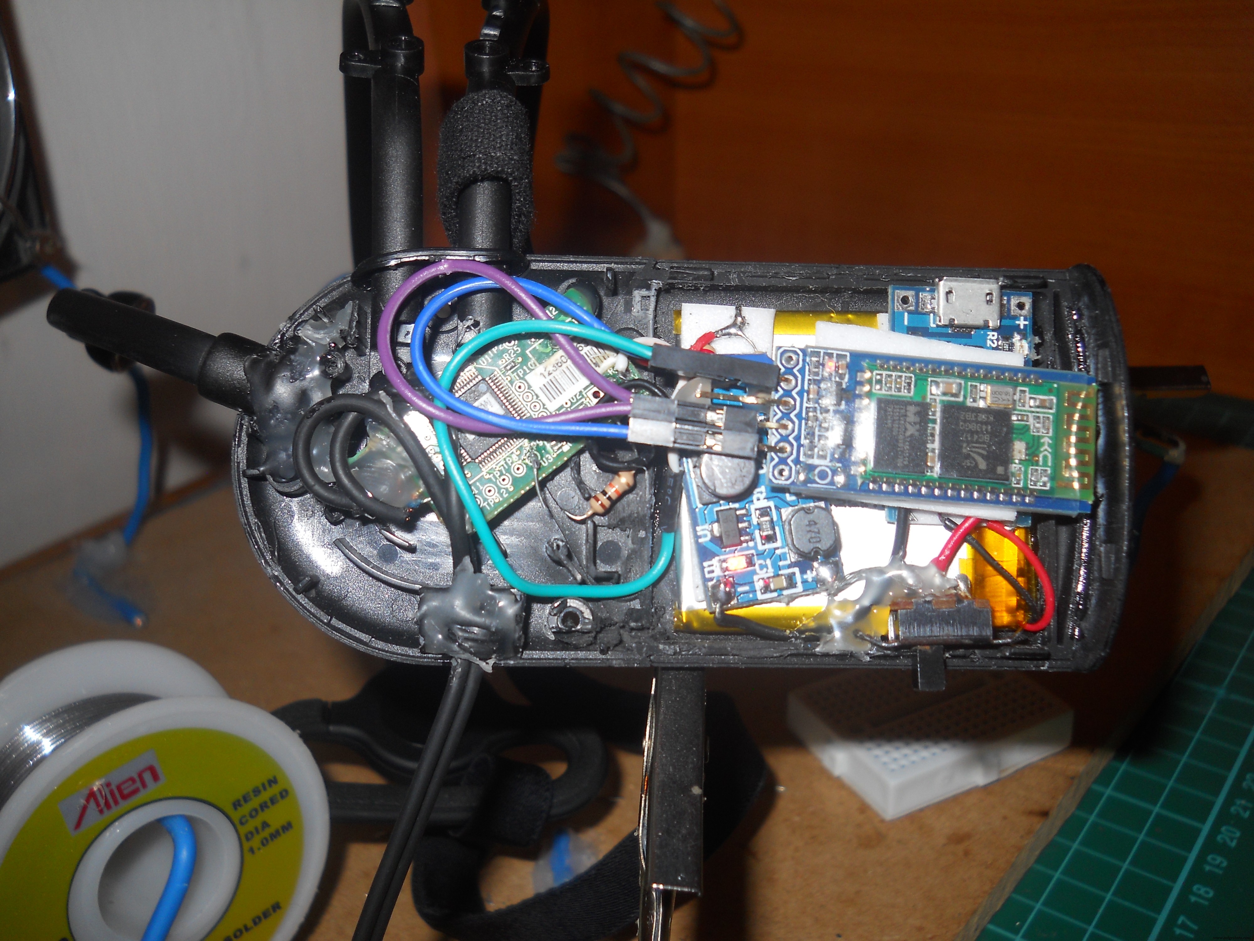
가장 중요한 부분은 "T" 핀을 Bluetooth 모듈의 "RX"에 연결하는 것입니다. 이것은 우리의 프로젝트에 생명을 불어넣습니다.
블루투스 모듈 구성
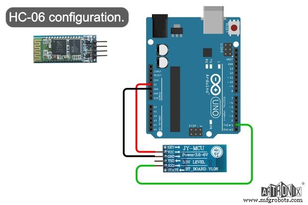
HC-06:먼저 "HC_06_Bluetooth"라는 이름의 스케치를 로드합니다. Arduino UNO에 연결한 다음 회로도와 같이 Bluetooth 모듈을 연결합니다. Artronix 팀의 웹사이트에서 이 회로도를 발견했고 유용해 보였습니다.
void setup() { // 하드웨어 시작 serial.Serial.begin(9600); // 기본 HC-06 전송 속도delay(1000);Serial.print("AT");delay(1000);Serial.print("AT+VERSION");delay(1000);Serial.print("AT+PIN "); // passworddelay(1000) 제거;Serial.print("AT+BAUD7"); // 전송 속도를 576000으로 설정 - 예:Necomimi dafaultdelay(1000);Serial.begin(57600); // 지연(1000);}무효 루프() {} Arduino IDE에서 직렬 모니터를 열고 Arduino가 BT 모듈을 구성할 때까지 기다립니다. 이제 Bluetooth 모듈이 57600baud rate로 설정되었습니다. . 이 해킹된 블루투스 Necomimi 장난감은 모든 Neurosky 앱과 호환되기 때문에 많은 BCI(Brain Computer Interface) 앱을 시험해 볼 수 있습니다.
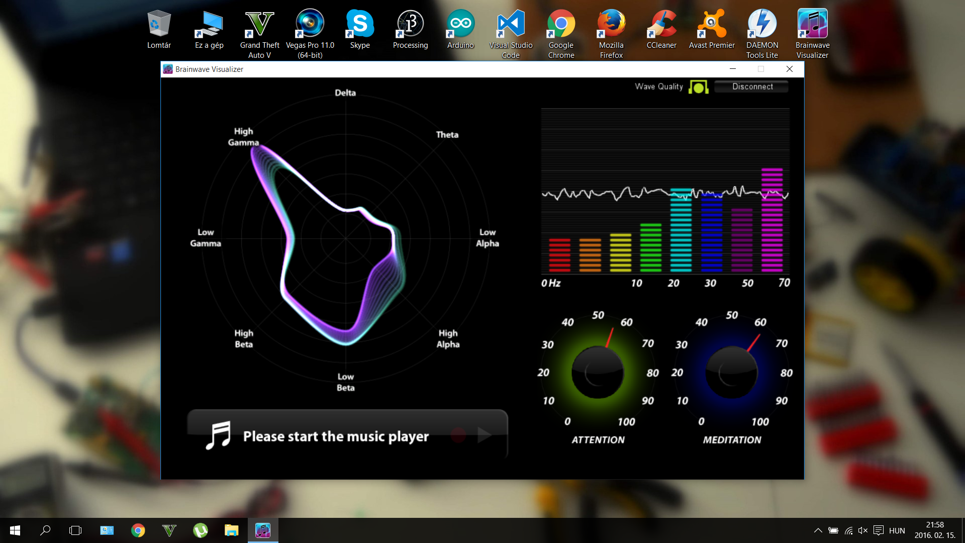
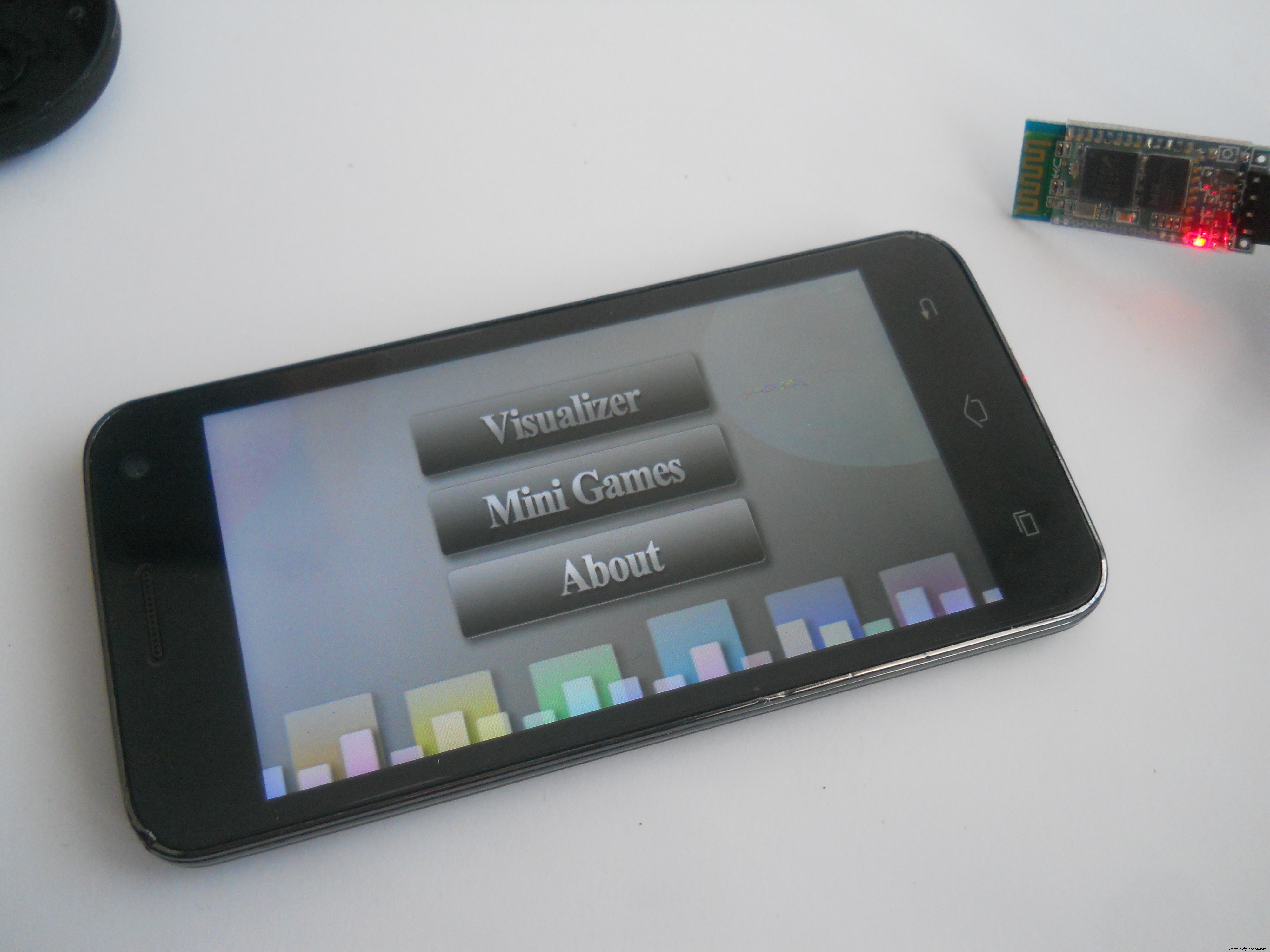


이러한 앱을 사용하여 주의력이나 명상과 같은 뇌파와 가치를 제어하는 방법을 배울 수 있습니다. 멋진 게임을 많이 시도할 수 있지만 다음 앱을 추천합니다(PC, iOS 및 Android와 호환됨).
http://store.neurosky.com/products/brainwave-visualizer-android
http://store.neurosky.com/products/eeg-analyzer
http://store.neurosky.com/collections/android/products/blink-camera-android
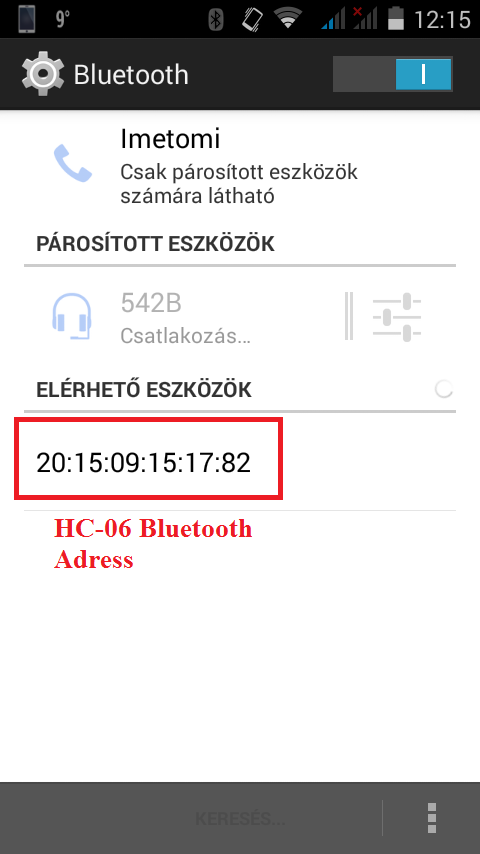
그런 다음 "HC_05_Bluetooth"를 사용합니다. 이전과 같은 방식으로 Arduino에 로드합니다. HC-05의 "EN"핀을 Arduino의 3v3에 연결하십시오. 코드에 HC-06 모듈의 주소를 적어야 합니다. 저같은 안드로이드 스마트폰으로 BT 모듈의 주소를 확인해보세요. 코드에서 ":"(이중 점)를 "," 쉼표로 바꿉니다.
코드에서 주소를 변경해야 합니다.
20:15:09:15:17:82 ==> 2015,09,151782 이런 식으로 HC-05 모듈은 주소를 인식할 수 있습니다. 따라서 일부 ":"는 필요하지 않으므로 그대로 두십시오.
// HC-05 configurationvoid setup() { // 하드웨어 직렬을 시작합니다. Serial.begin(9600); // 기본 HC-05 전송 속도 지연(1000); Serial.print("AT"); 지연(1000); Serial.print("AT+버전"); 지연(1000); Serial.println("AT+ROLE=1"); // HC-05를 마스터 모드로 설정합니다. delay(1000); Serial.println(" AT+LINK="여기에 주소 복사"); //이제 모듈은 자동으로 연결되어야 합니다. delay(1000); Serial.print("AT+UART=57600,1,0"); // 설정 576000으로 전송 속도 Serial.begin(57600); // delay(1000);}void 루프() {}
마지막으로 두 모듈이 서로 연결되어야 합니다. 문제가 있는 경우 이 링크를 클릭하여 자세한 내용을 읽으십시오.
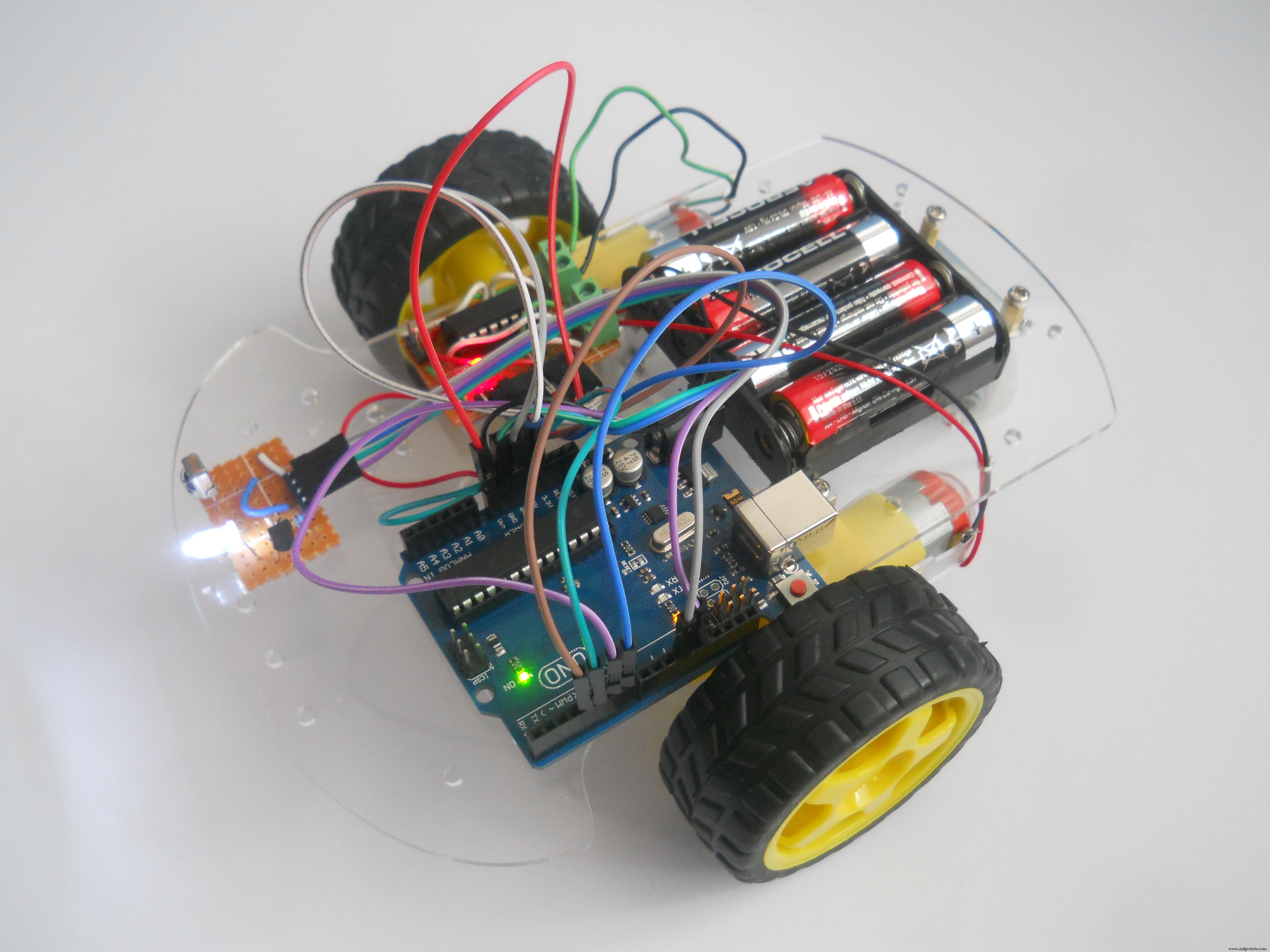
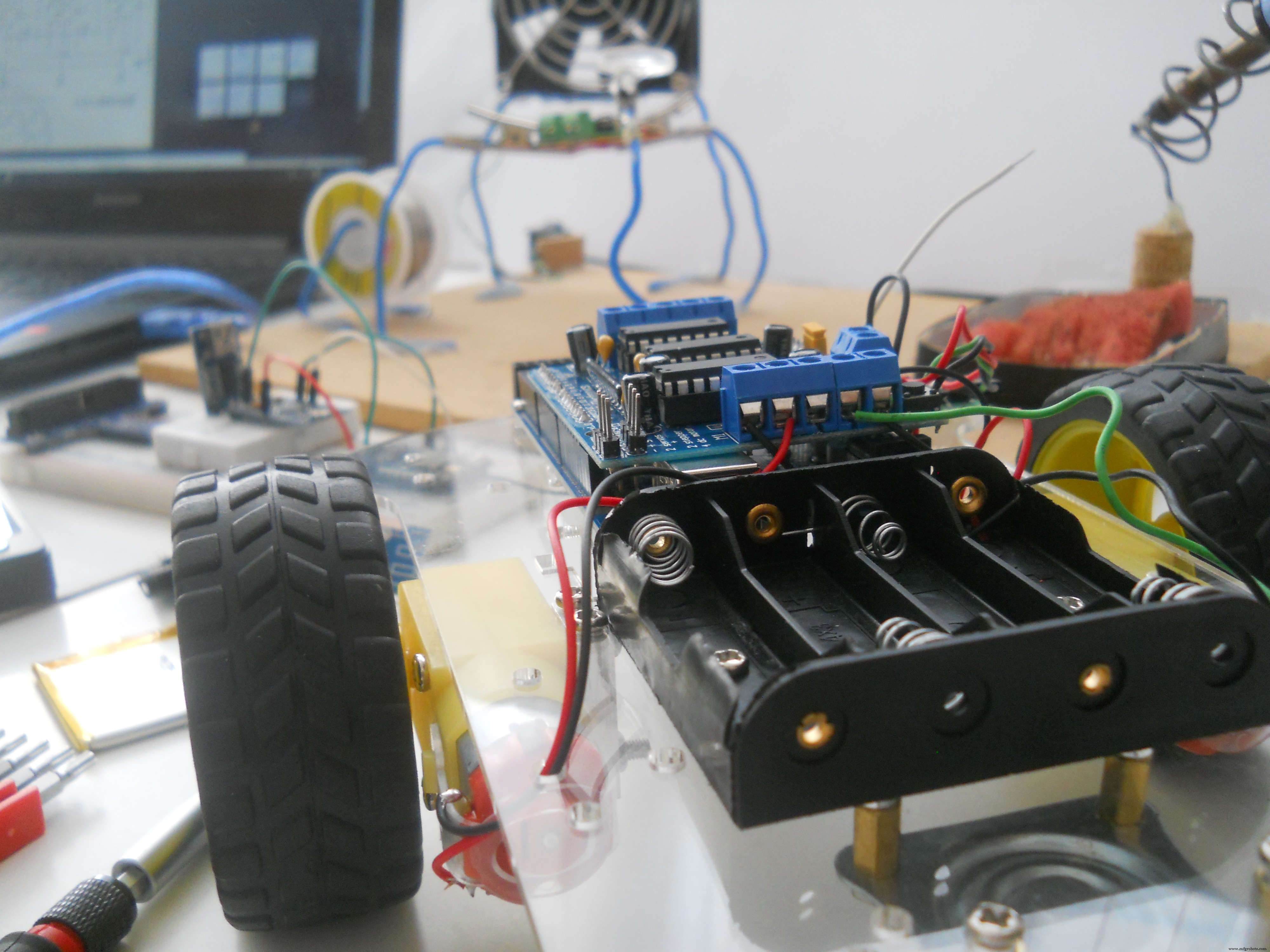
원격 제어 로봇
이 저렴한 로봇을 만들기 위해 38kHz IR 기술을 사용했습니다. , TV 리모컨에 사용됩니다. 나는 내 로봇을 위해 Amazon achassis에서 샀습니다. IR 수신기는 오래된 TV에서 회수했으며 TheArduino도 Amazon에서 가져온 것입니다. 부품에 대한 링크를 추가했습니다(하드웨어 섹션의 아래 참조).
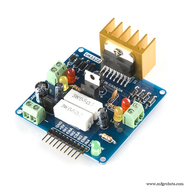
모터 드라이버 회로
다음 부품이 필요합니다.
<울>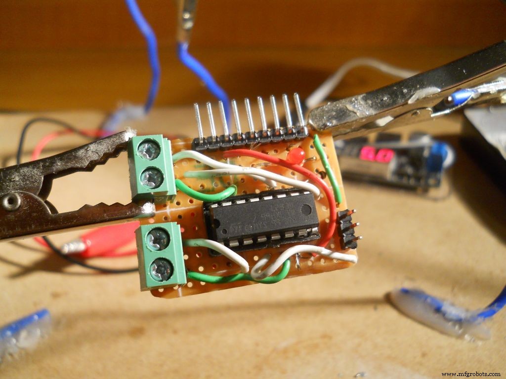
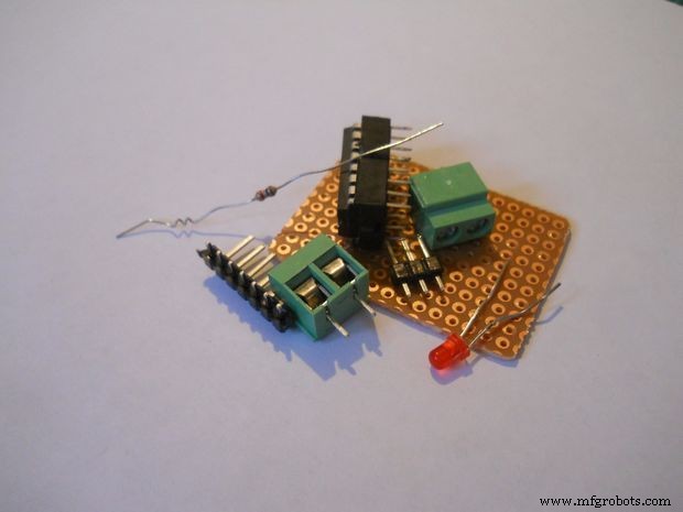
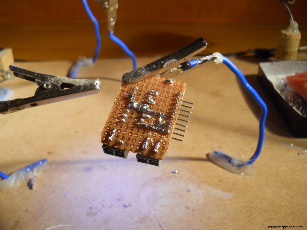
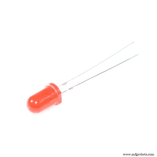
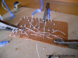
일부 구리선을 사용하고 회로도에 따라 IC의 핀을 헤더 핀에 연결했습니다. 어떤 핀이 어떤 헤더 핀에 연결되는지는 중요하지 않습니다. 연결했는지 기억하십시오. LED는 저항과 직렬로 연결되고 5v VCC와 병렬로 연결됩니다.
섀시 조립
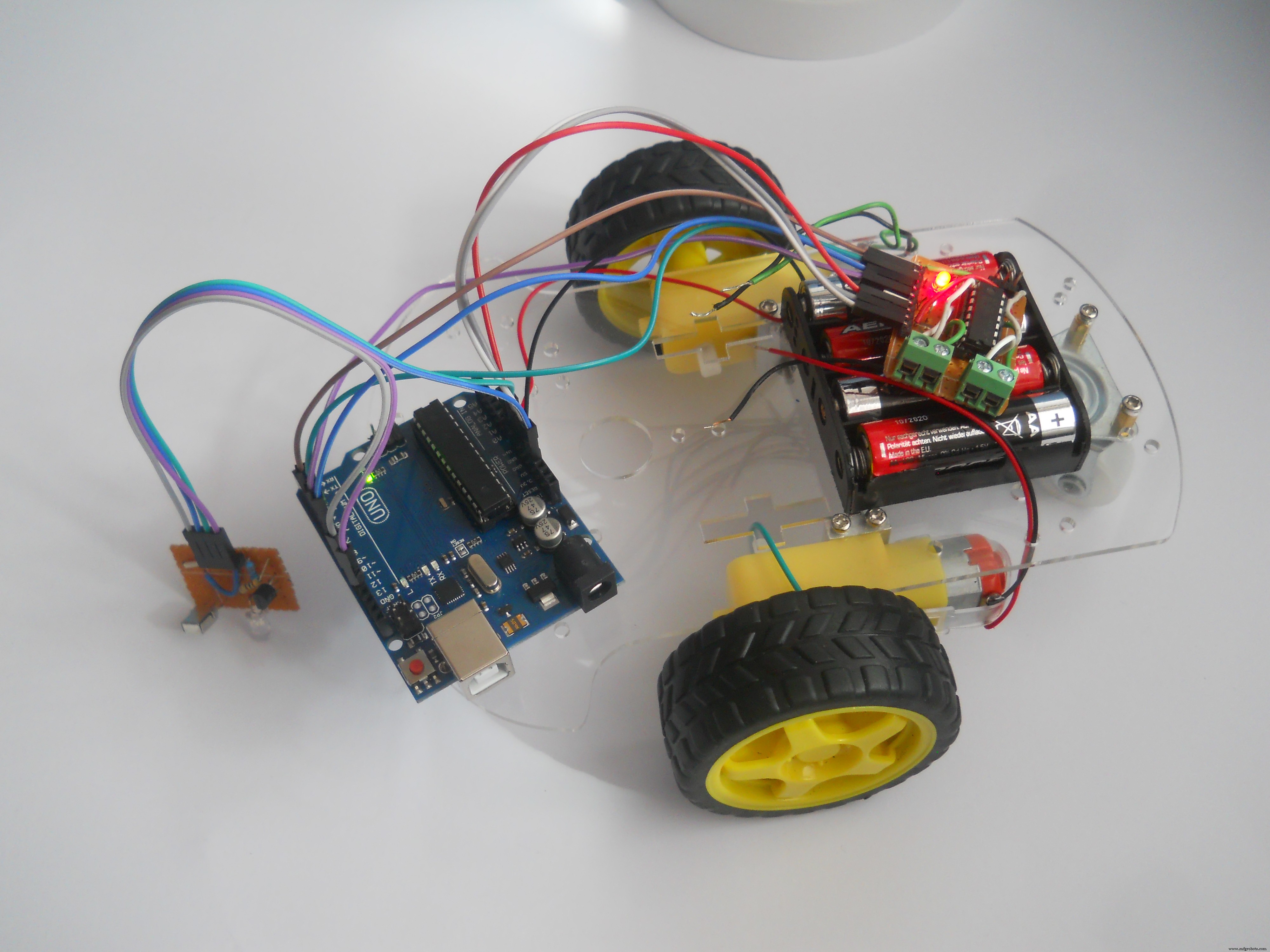
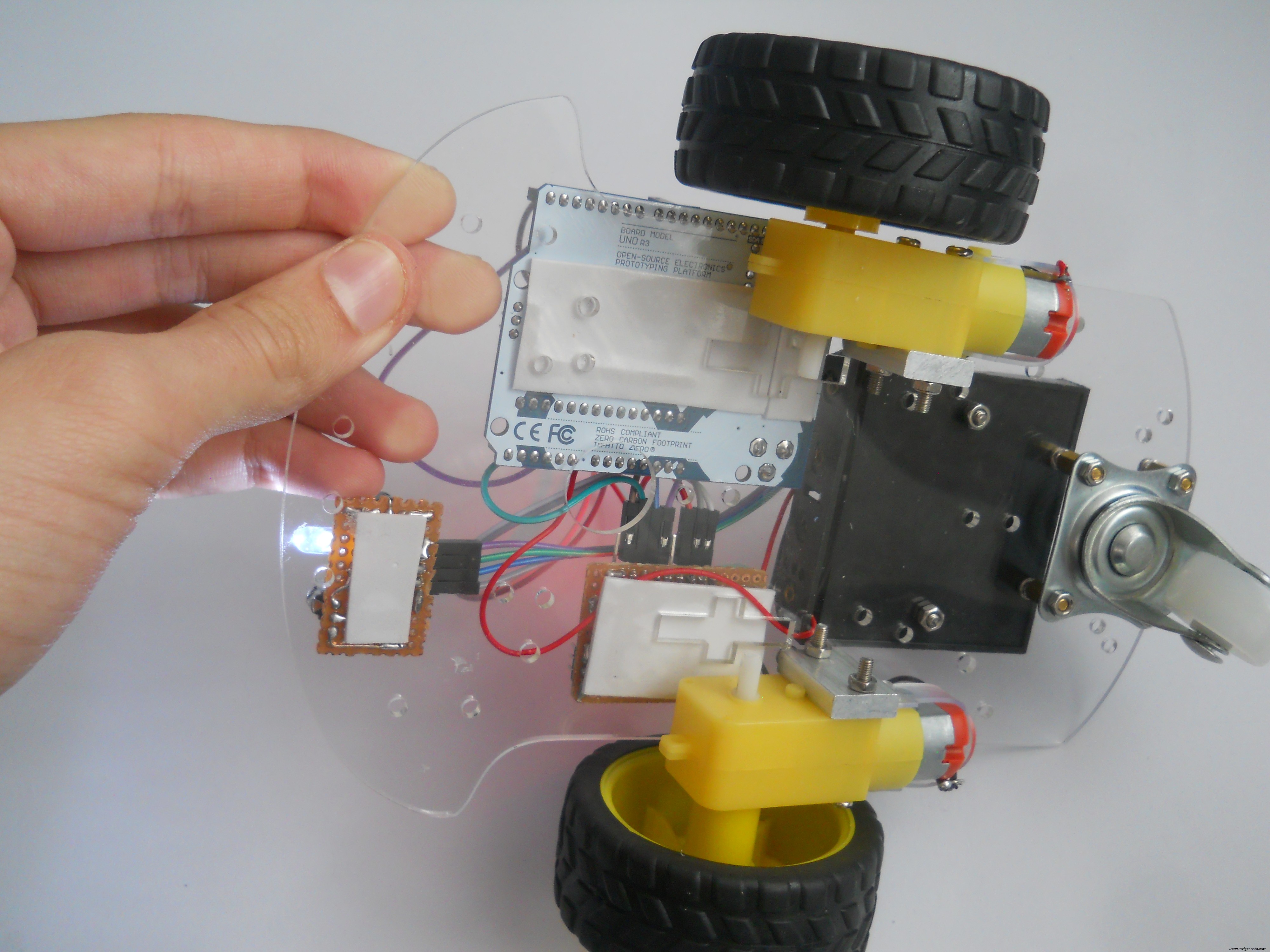
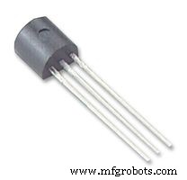
이 단계는 매우 쉬웠고 드라이버와 약간의 공예 기술을 사용하여 5분 만에 프레임을 만들었습니다. 이것이 더 어려운 부분이 된 후에 우리는 모터 드라이버 회로를 만들어야 합니다. 내 모터를 제어하려면 두 개의 모터를 구동할 수 있는 L293D IC를 선택합니다. 회로도를 빌드하십시오.
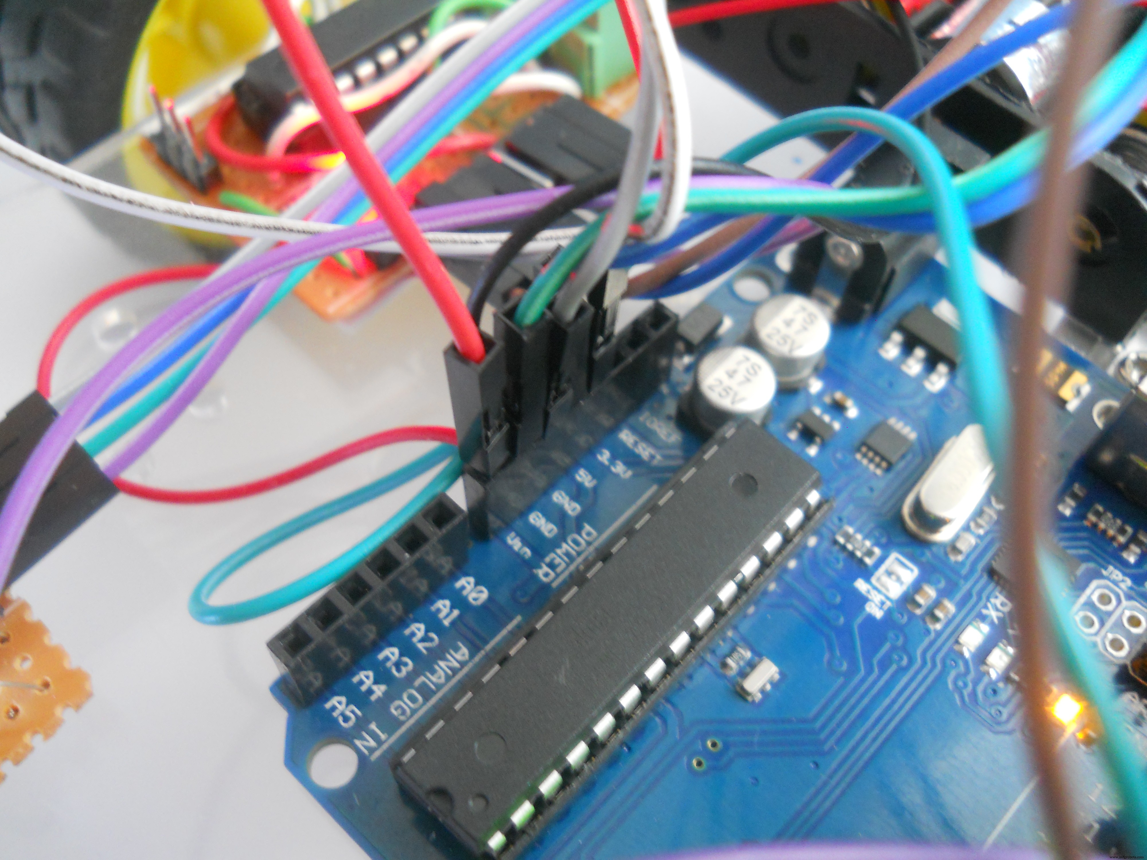
부품을 Arduino에 연결
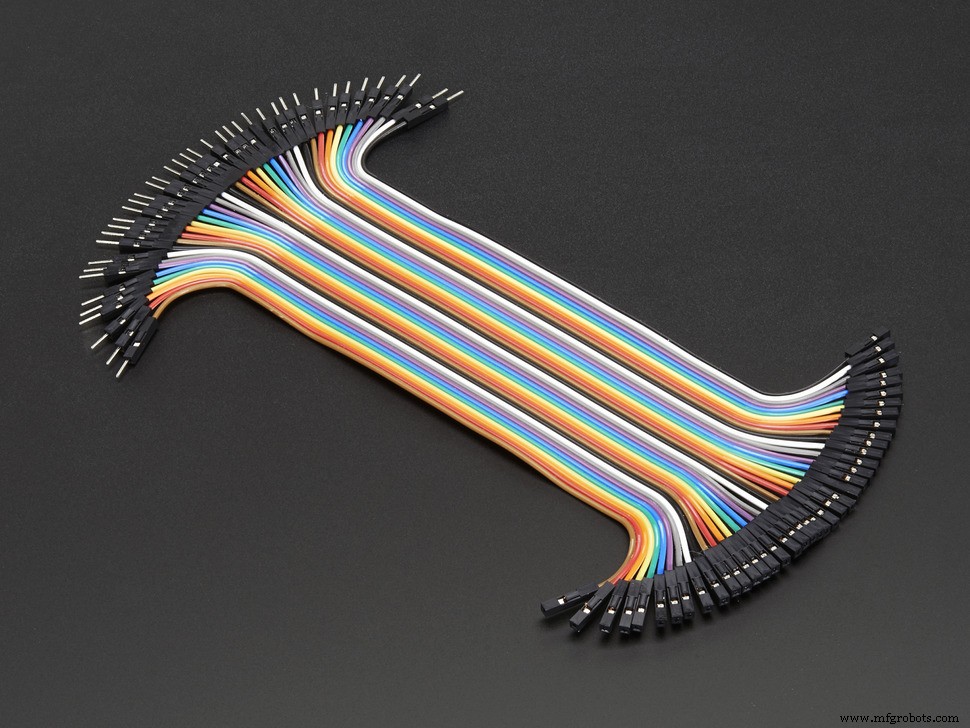
센서와 모터 드라이버를 Arduino에 연결하기 위해 점퍼선을 사용했습니다.
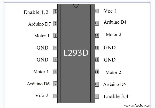
Arduino 핀 ==> 모터 드라이버
4 ==> 15
5 ==> 10
6 ==> 7
7 ==> 2
VIN ==> 8
5v ==> 1, 9, 16
GND ==> 4, 5, 13, 12
따라서 L293D 모듈의 회로도를 보고 여기에 쓴 것처럼 핀을 Arduino UNO에 연결합니다. 5v 핀 Arduino의 1, 9, 16 핀에 연결해야 합니다. IC의 모터 드라이버 기능을 활성화합니다. 그런 다음 마지막으로 나사 단자를 사용하여 모터의 전원을 켭니다.

코드 작성 중...
IRremote 라이브러리를 사용하여 38kHz 적외선 신호를 읽고 디코딩한 다음 로봇을 움직이는 코드를 만들었습니다. (코드 섹션에서 라이브러리를 다운로드하십시오).
코드에 설명을 추가했지만 그 실체는 메인 서버에서 오는 IR 신호를 해독한 다음 사용자가 원하는 것에 따라 로봇을 앞으로 움직이거나 왼쪽으로 돌리는 것보다 모터를 움직인다는 것입니다. 코드 다운로드:"Robot_Code" . 이것을 Arduino에 로드하면 로봇이 완성됩니다.
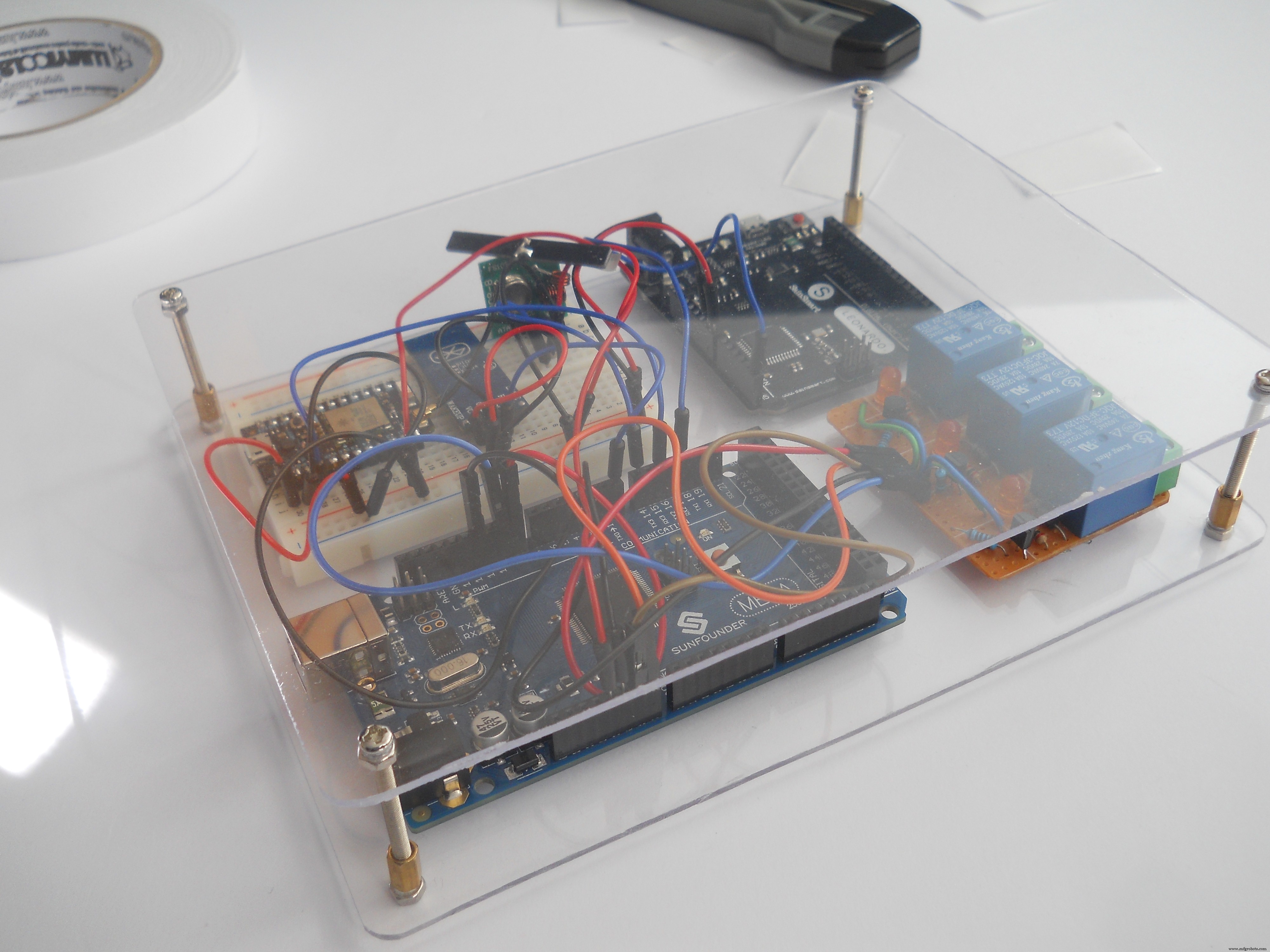
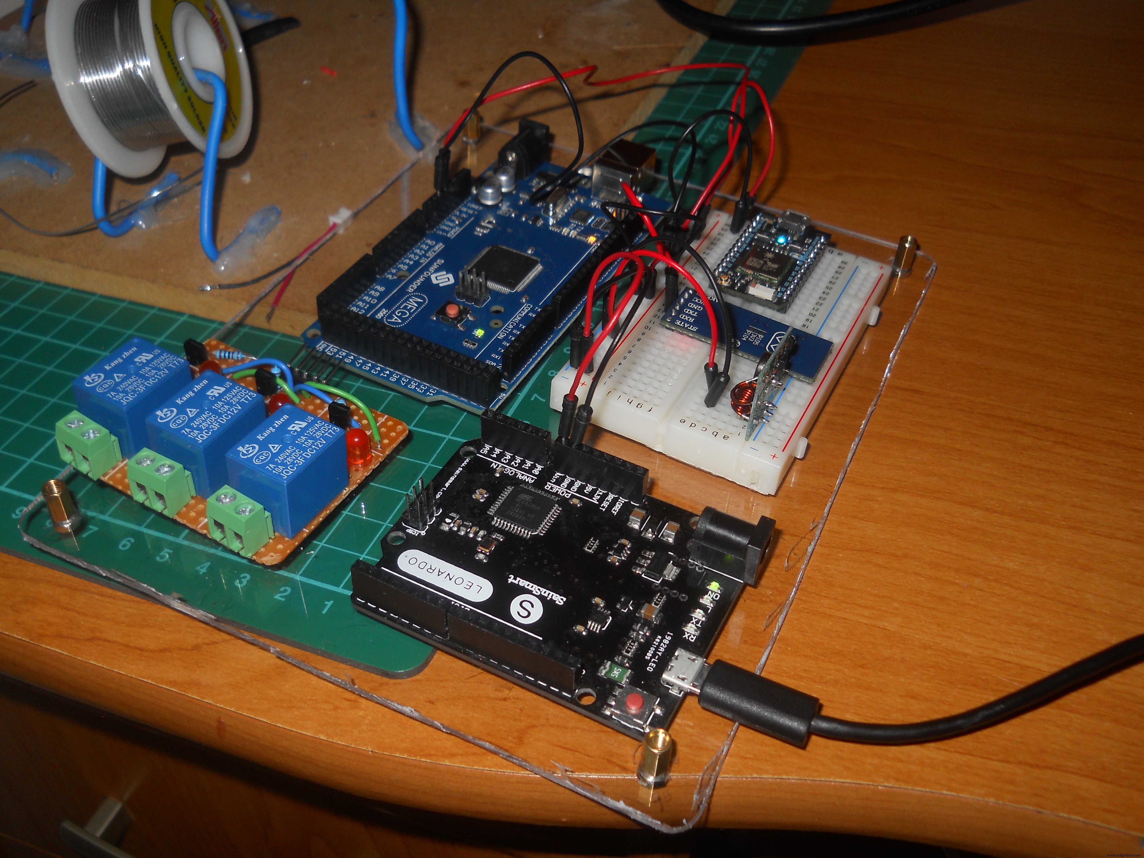
메인 서버(Arduino Mega, Leonardo, Photon)
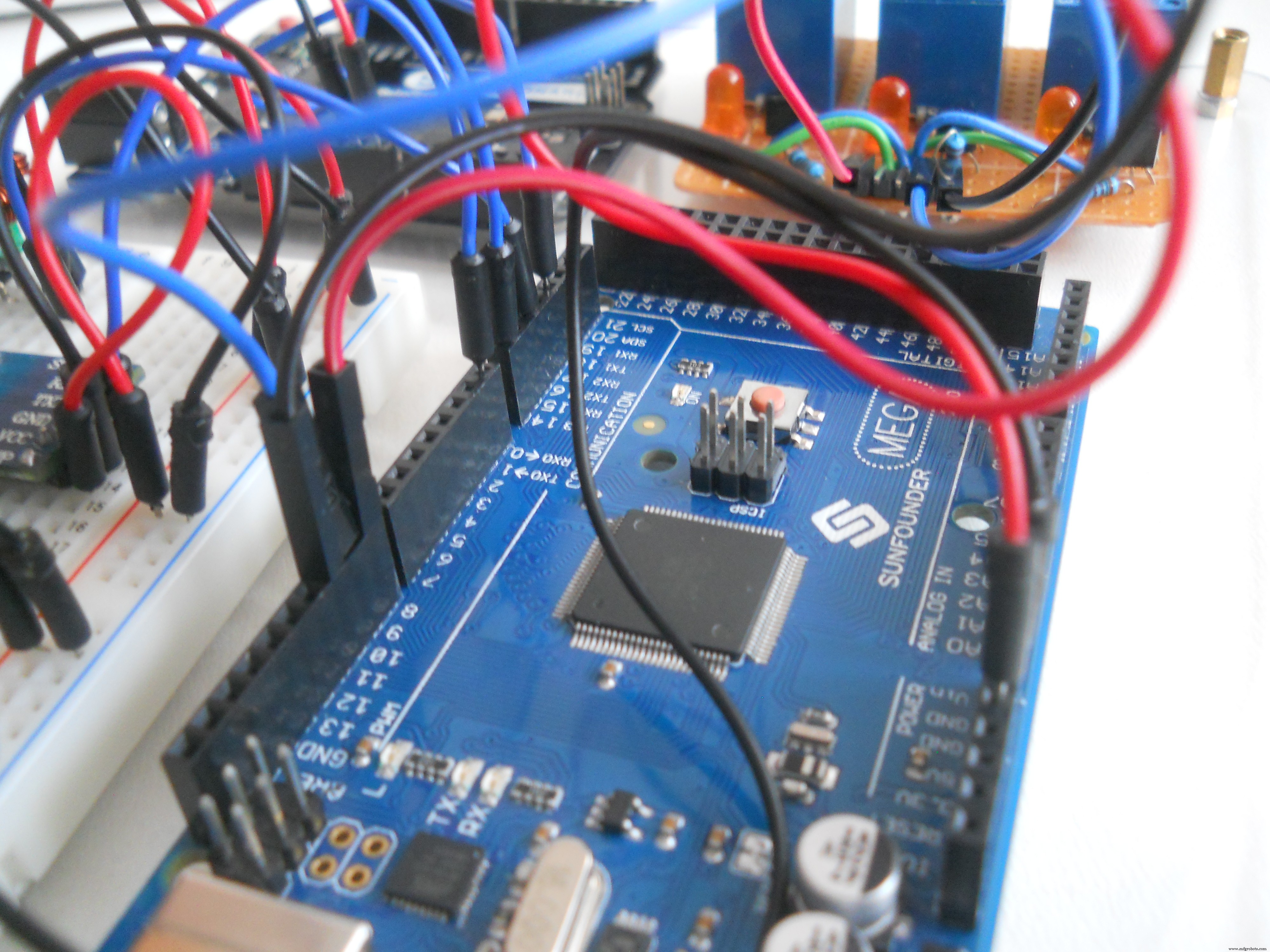
서버는 무선 헤드셋에서 들어오는 데이터 패킷을 읽습니다. 헤드셋과 서버 간의 연결을 보장하기 위해 구성된 BT 모듈을 사용합니다. Arduino Mega는 회로의 두뇌이며 Bluetooth, 적외선 송신기 LED, 웹 서버 및 마우스 컨트롤러와 같은 모든 것이 이 마이크로 컨트롤러에 연결됩니다. 코드가 조금 복잡하지만 이해를 돕기 위해 설명을 추가했습니다.
케이스
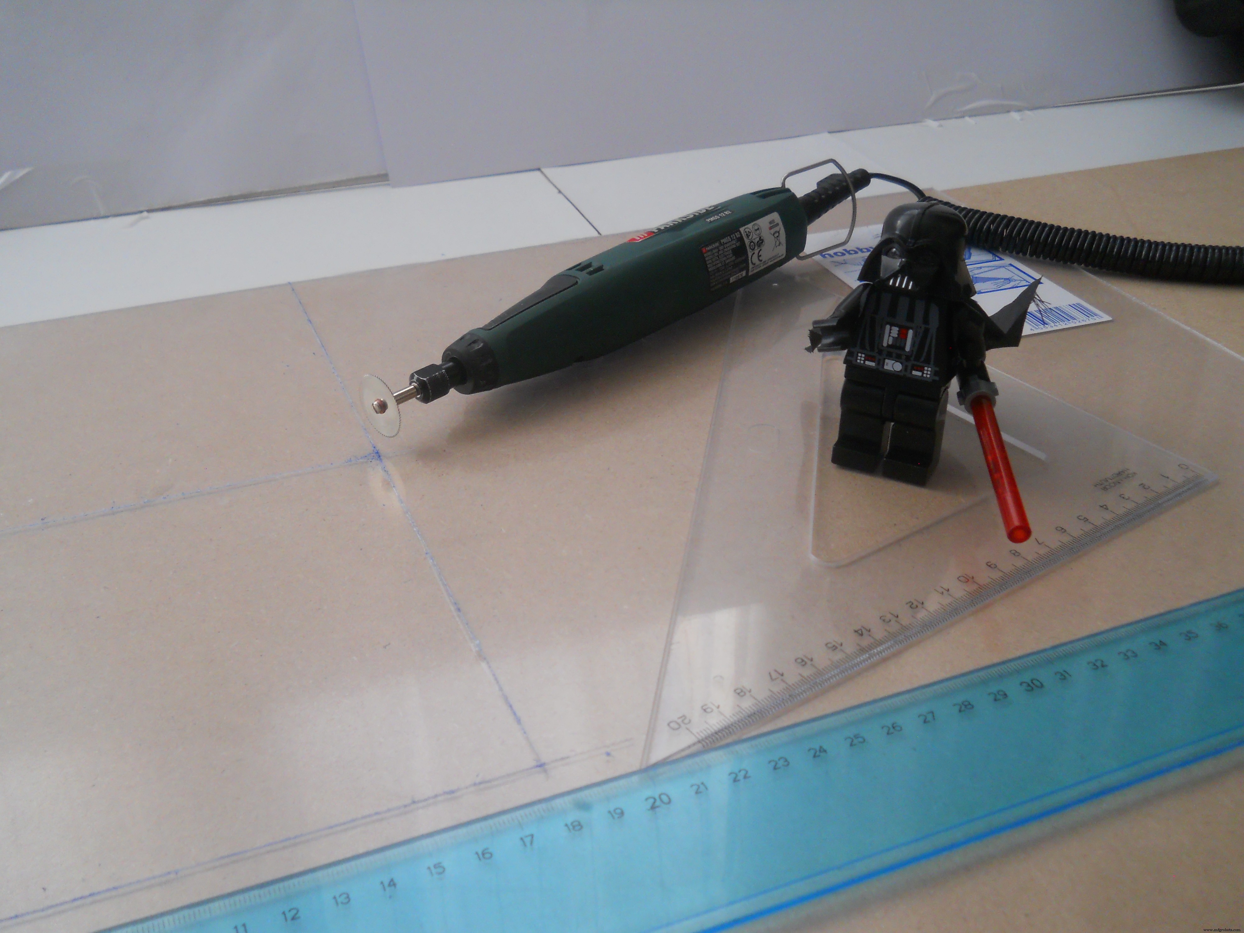

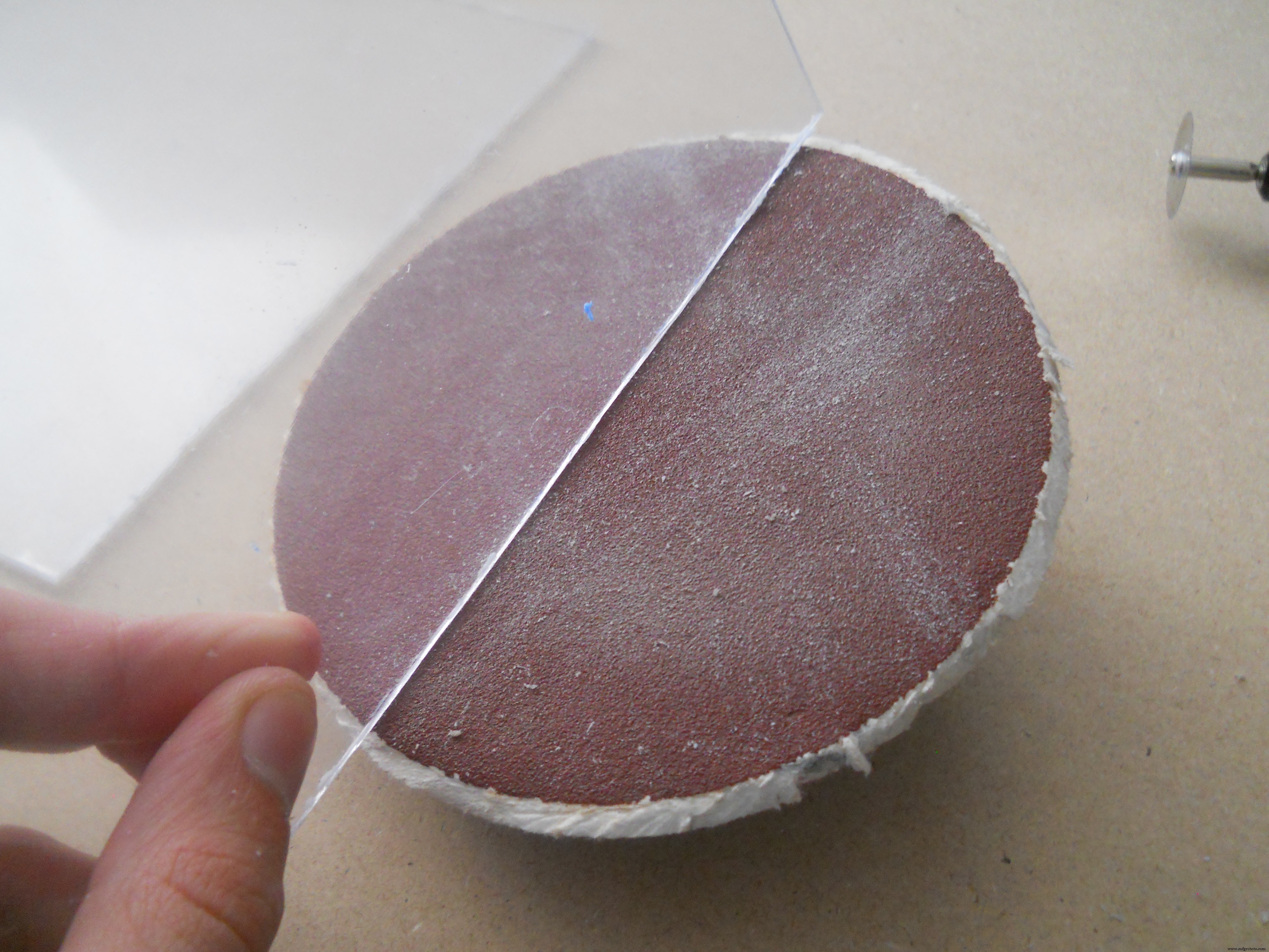
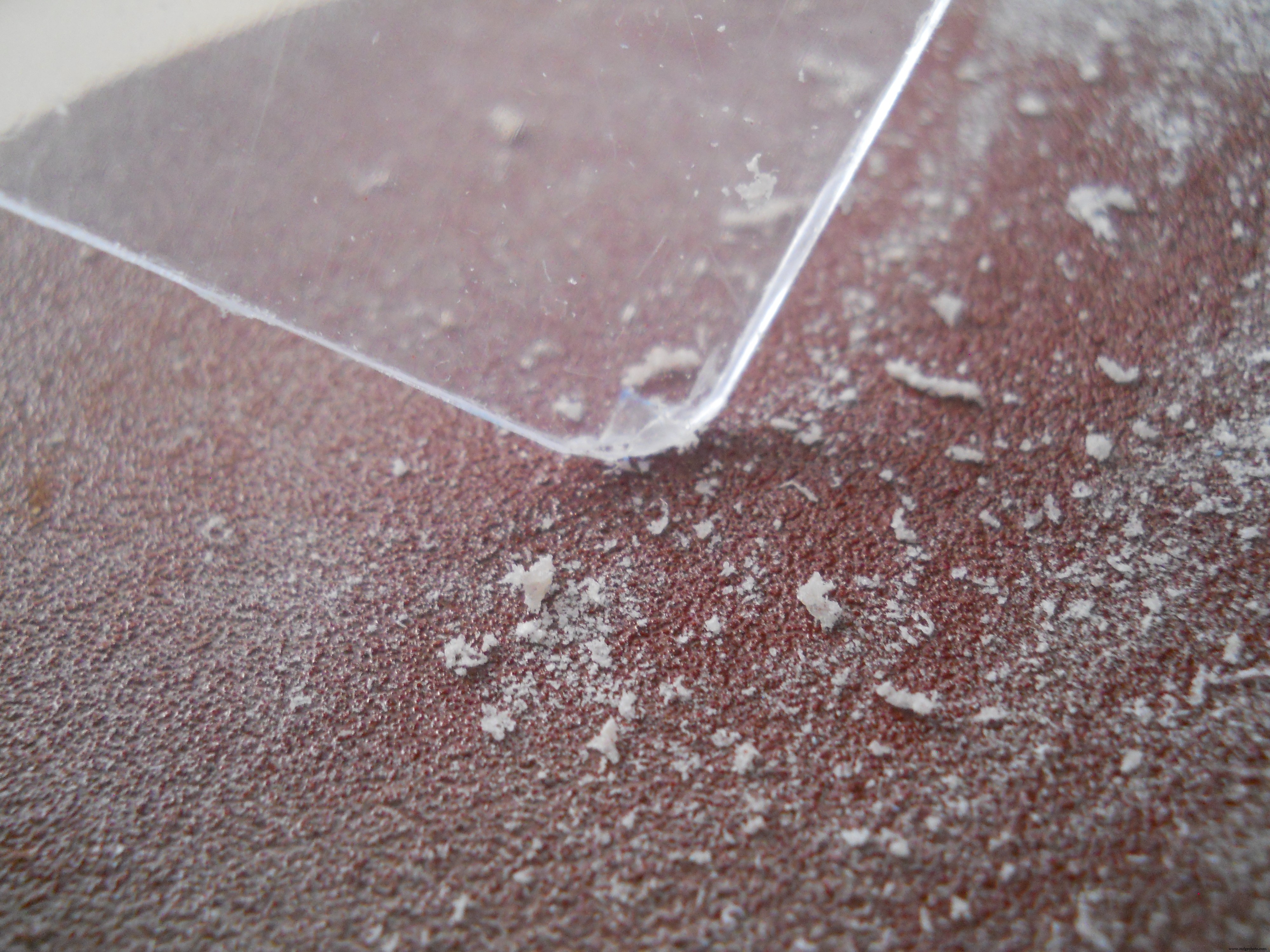
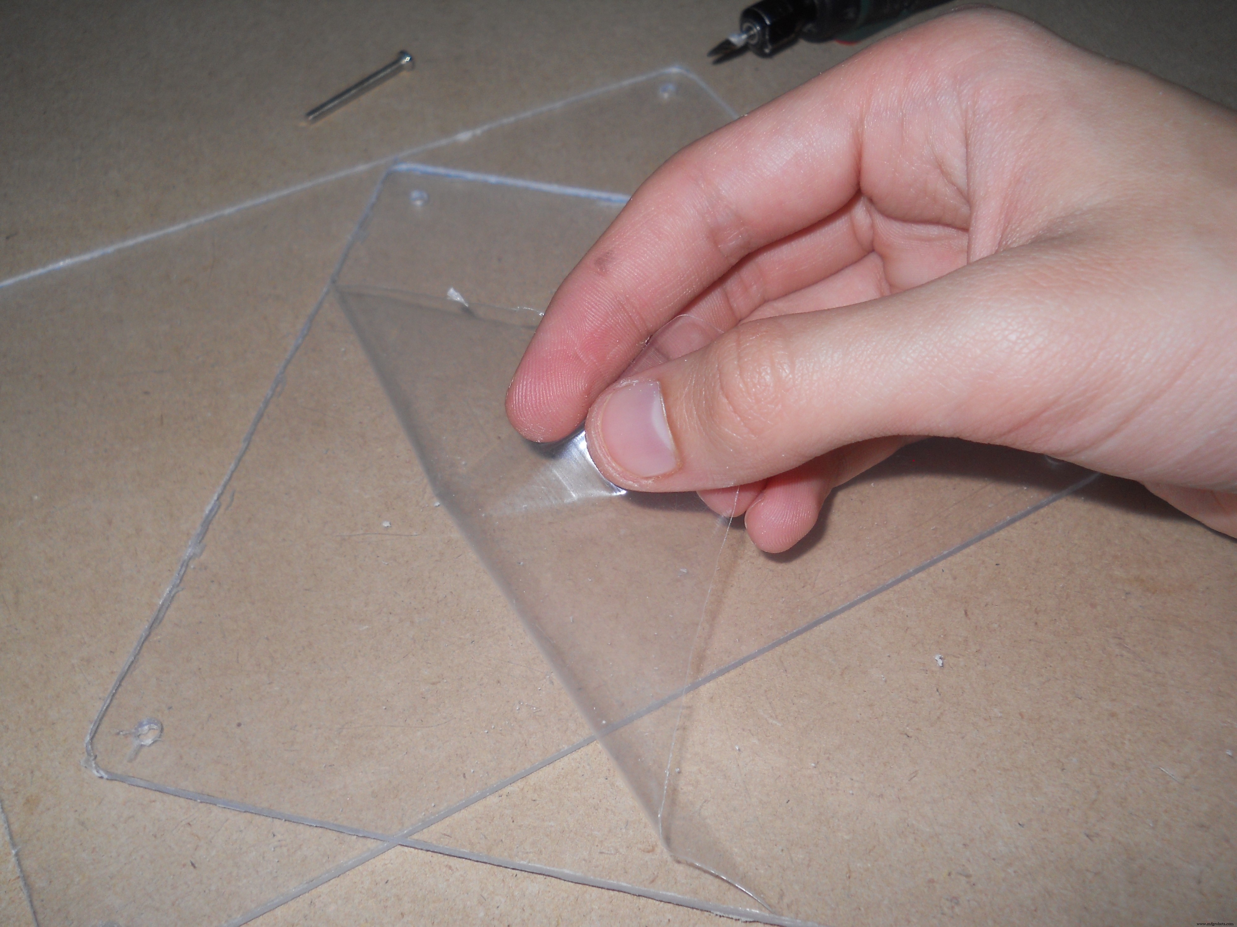
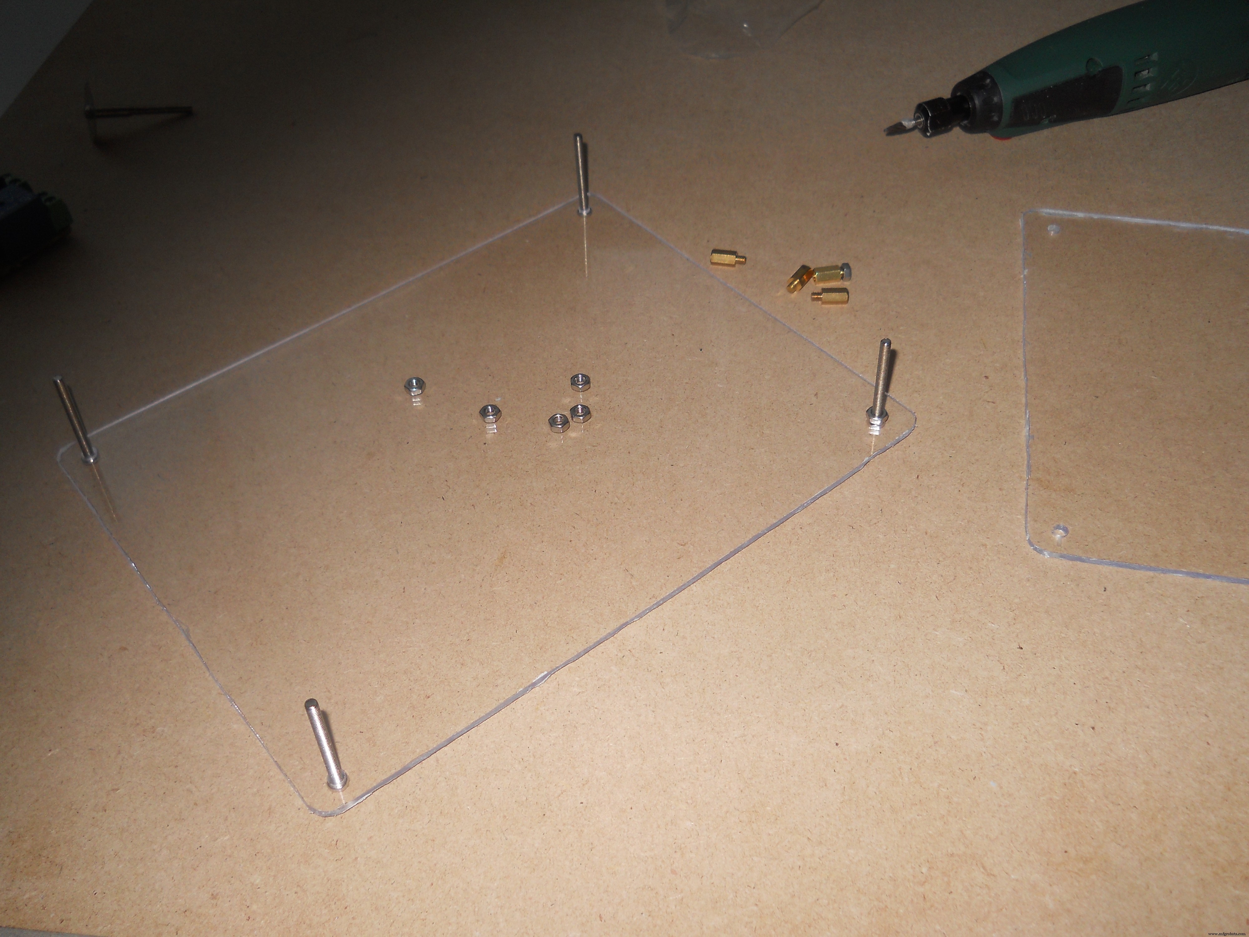
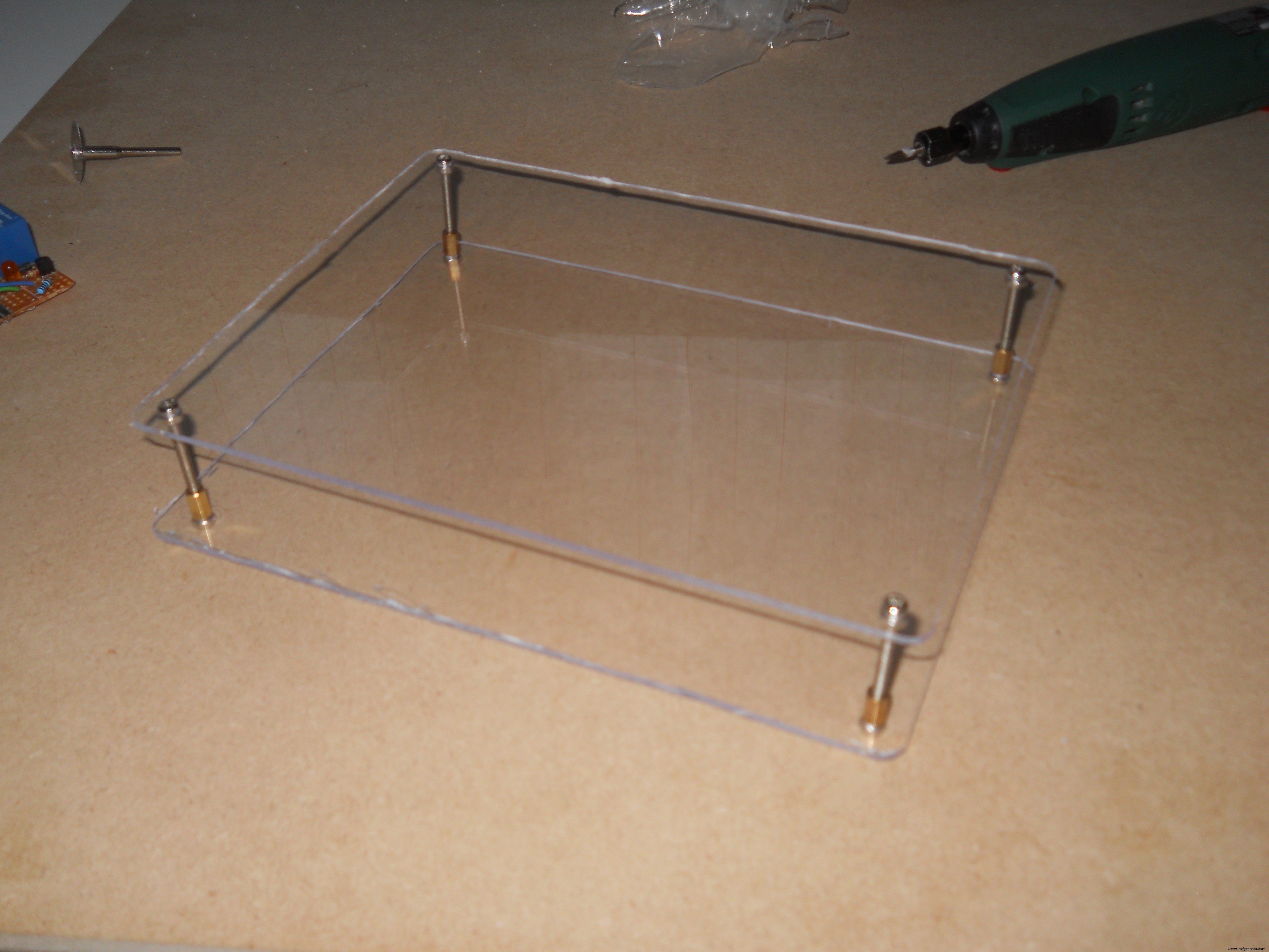
간단하지만 멋지게 보입니다. 나는 두 개의 18x15cm 판을 자르고 사포로 가장자리를 부드럽게했습니다. 나사를 이용해서 서로 연결했습니다.
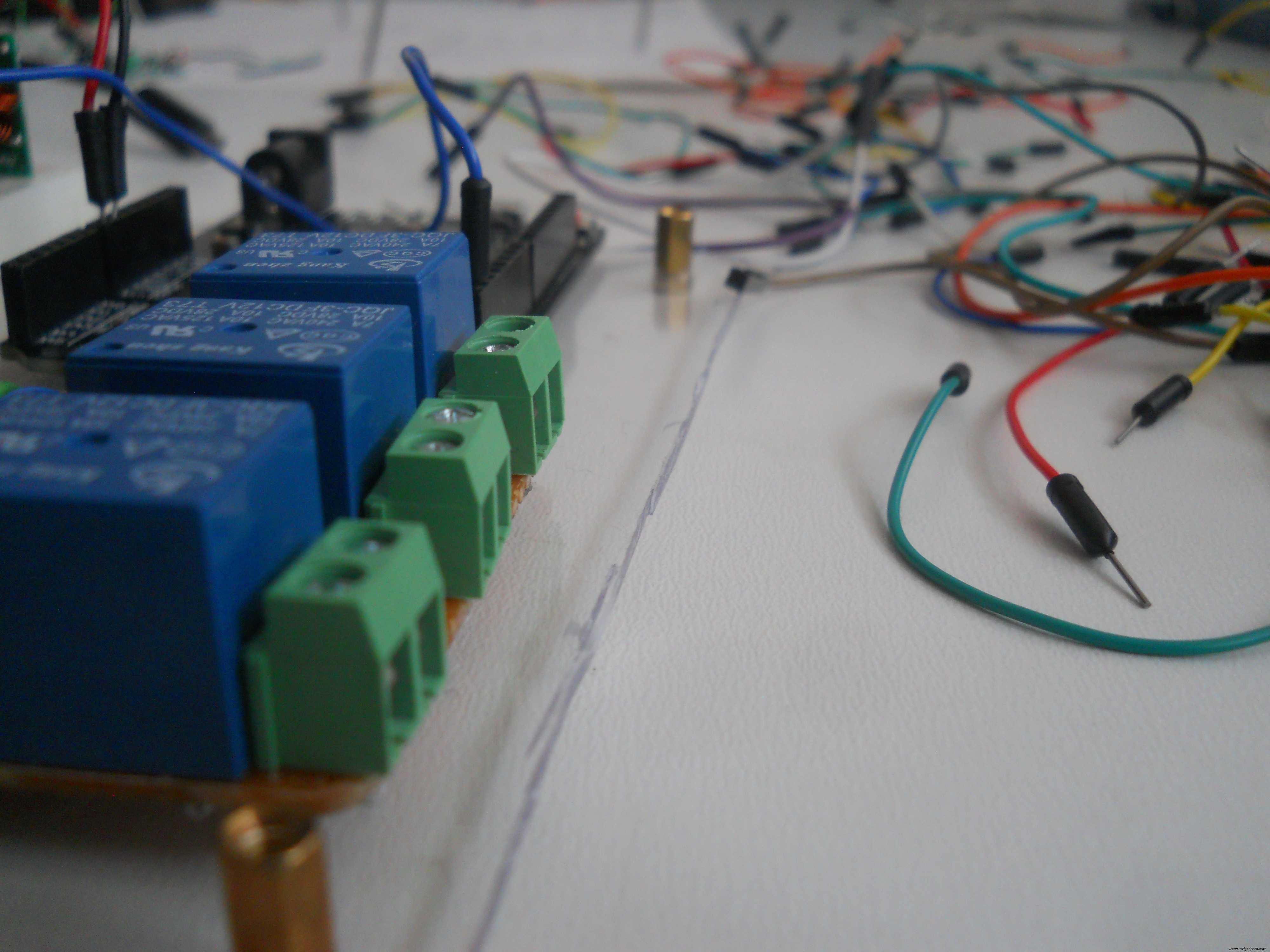
릴레이 회로
필요한 부품:
<울>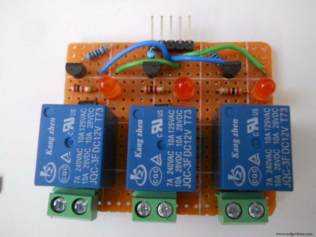
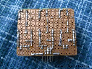
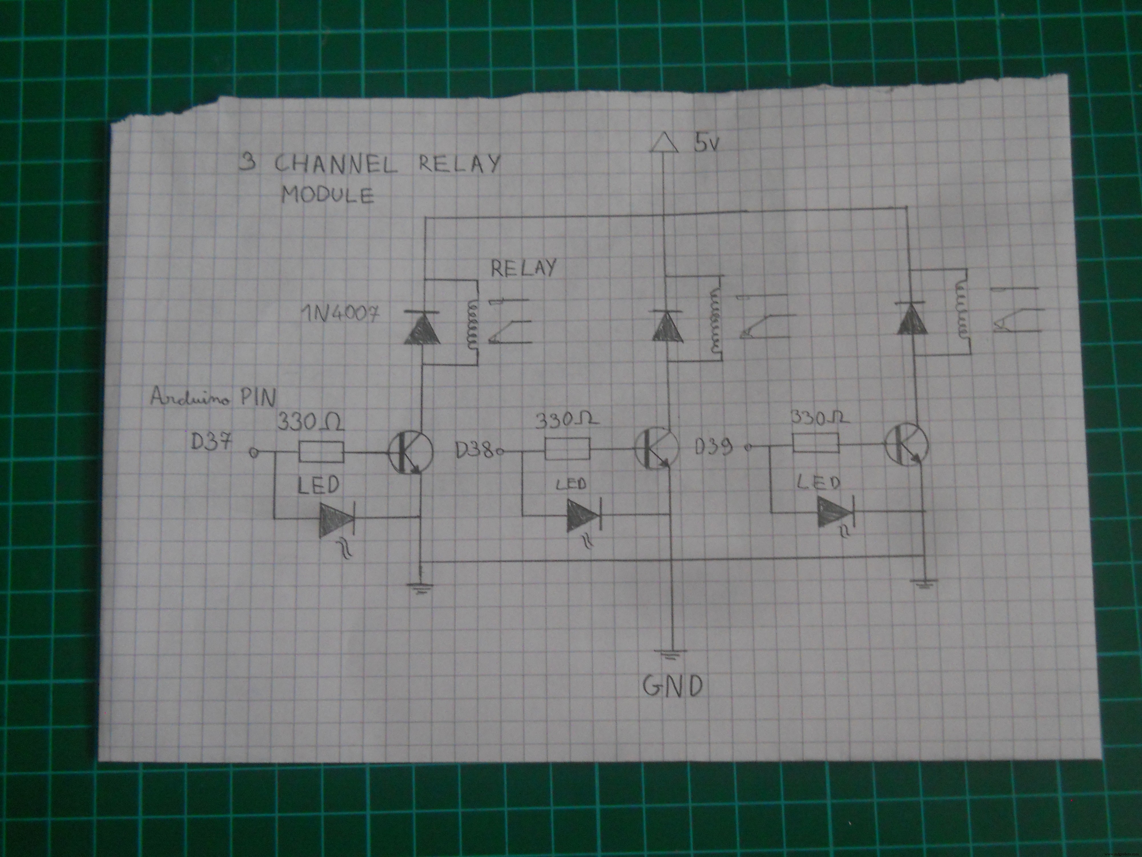
천 단어 이상의 가치가 있는 그림, 그래서 PCB의 부품을 어떻게 연결해야 하는지 글로 쓰려고 하는 대신 "Signal" 핀이 Arduino에서 신호를 받으면 릴레이가 켜집니다. 트랜지스터는 신호를 증폭하여 릴레이에 충분한 전력을 공급합니다. 37-38-39 핀을 사용하여 각 릴레이의 HIGH-LOW 레벨을 제어합니다.
케이스에 부품 설치
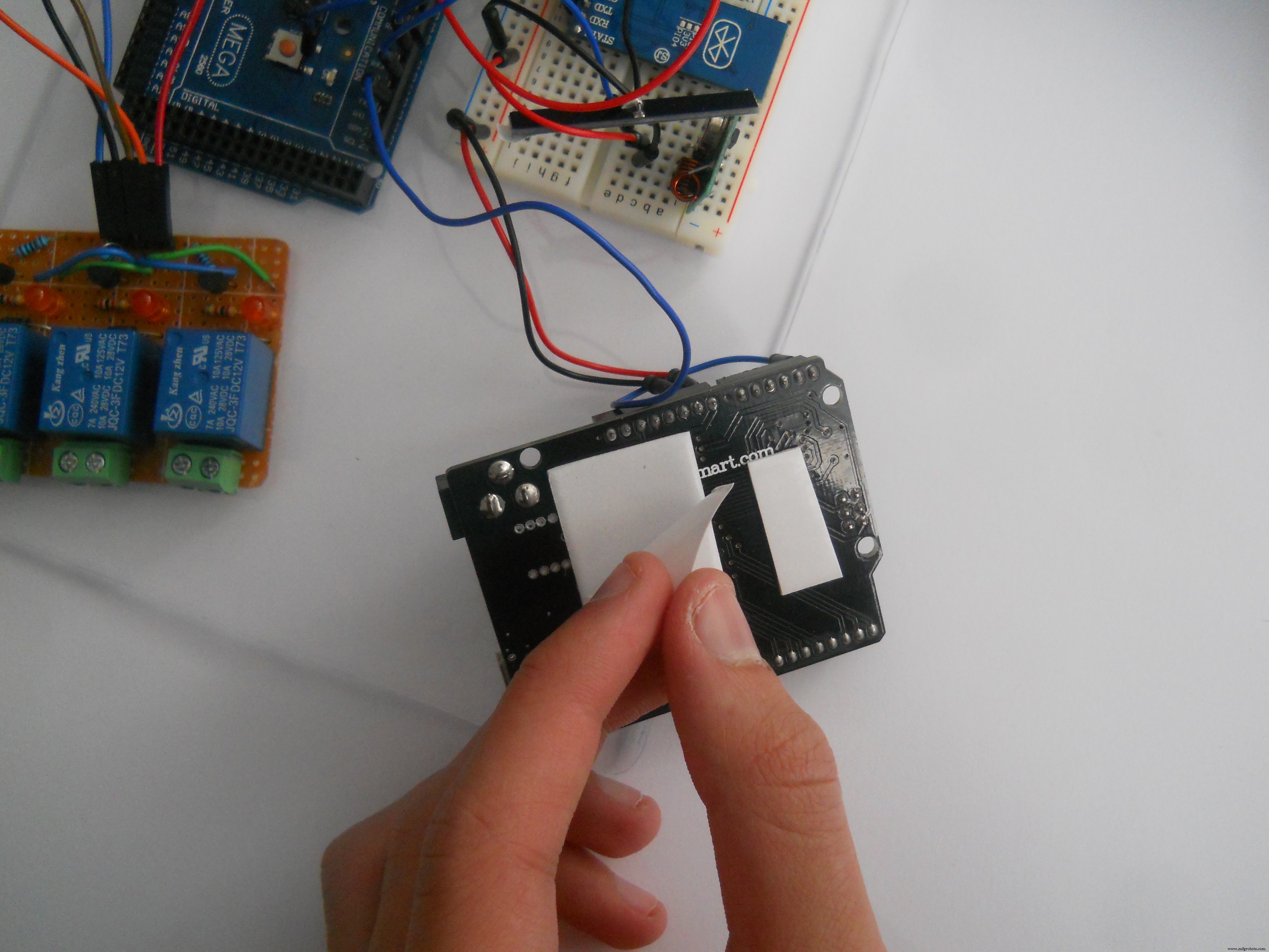


플렉시 유리 케이스에 부품을 설치하기 위해 양면 흰색 테이프를 사용했습니다. 이것은 눈에 띄지 않고 케이스의 회로를 꽤 강하게 고정시킵니다.
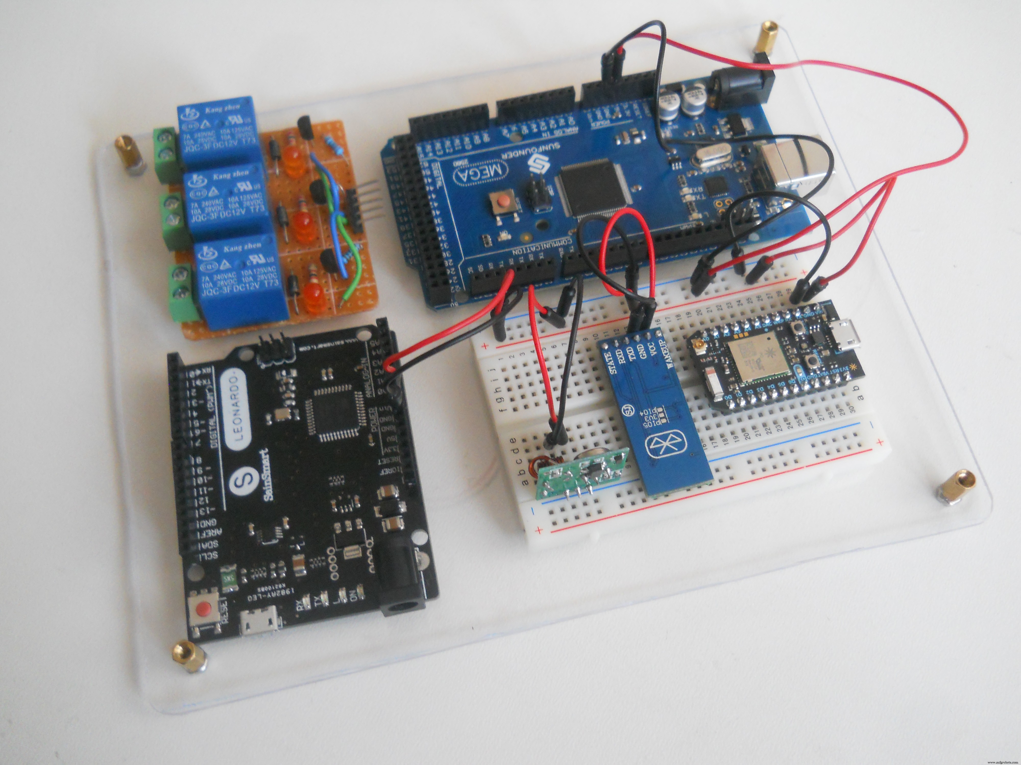
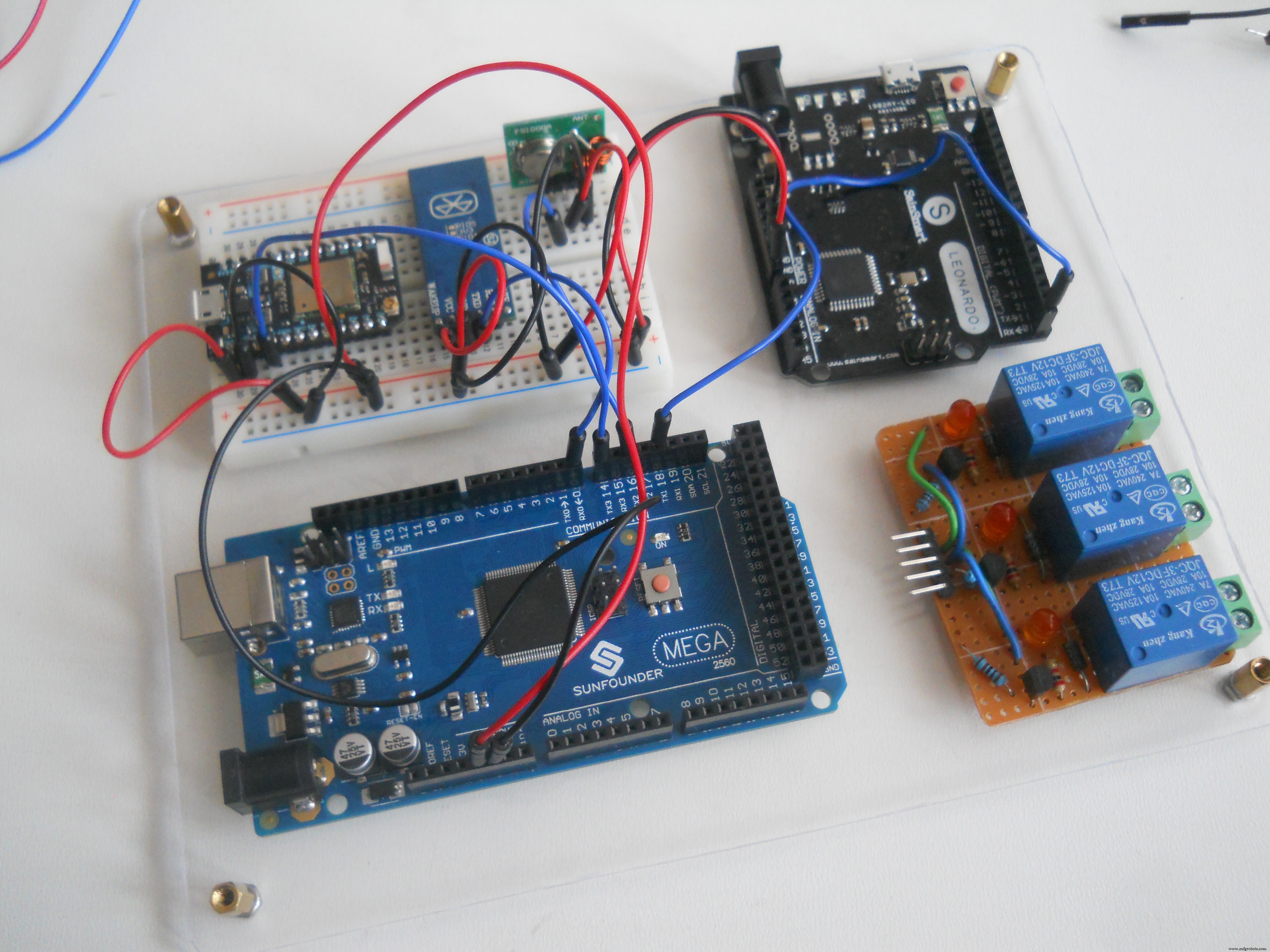
서버 회로
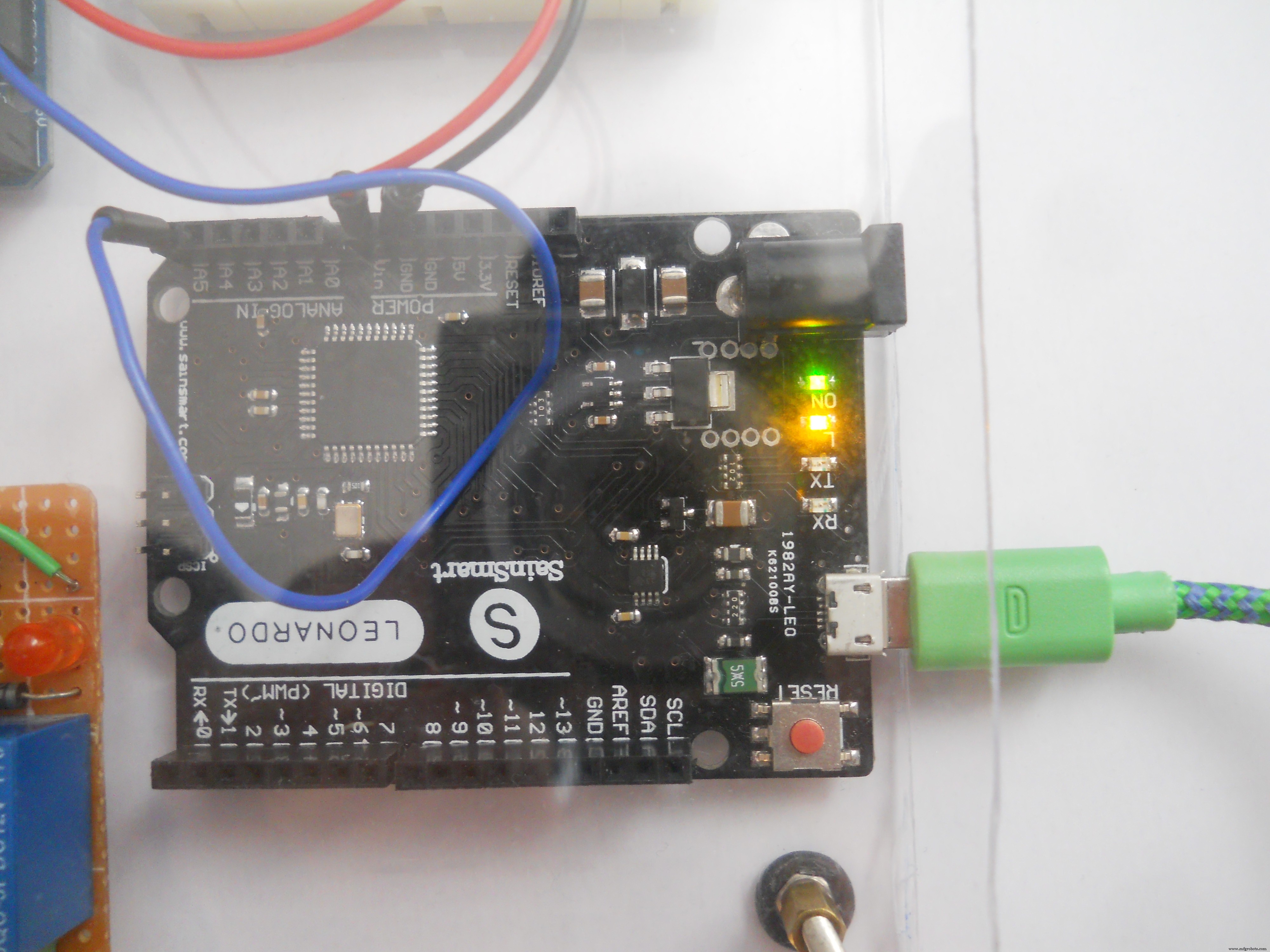
이 서버는 소프트웨어 기반이므로 회로를 만드는 것이 그리 어렵지 않습니다. (도식 다운너 참조). 마이크로컨트롤러의 전원을 켜고 이들 사이를 연결하기만 하면 됩니다. IR LED는 핀 D3에 연결되고 릴레이는 37-38-39에 연결됩니다. Arduino Mega의 D16은 Photon의 RX로, D18은 Leonardo의 RX로 연결됩니다.
로봇과의 연결
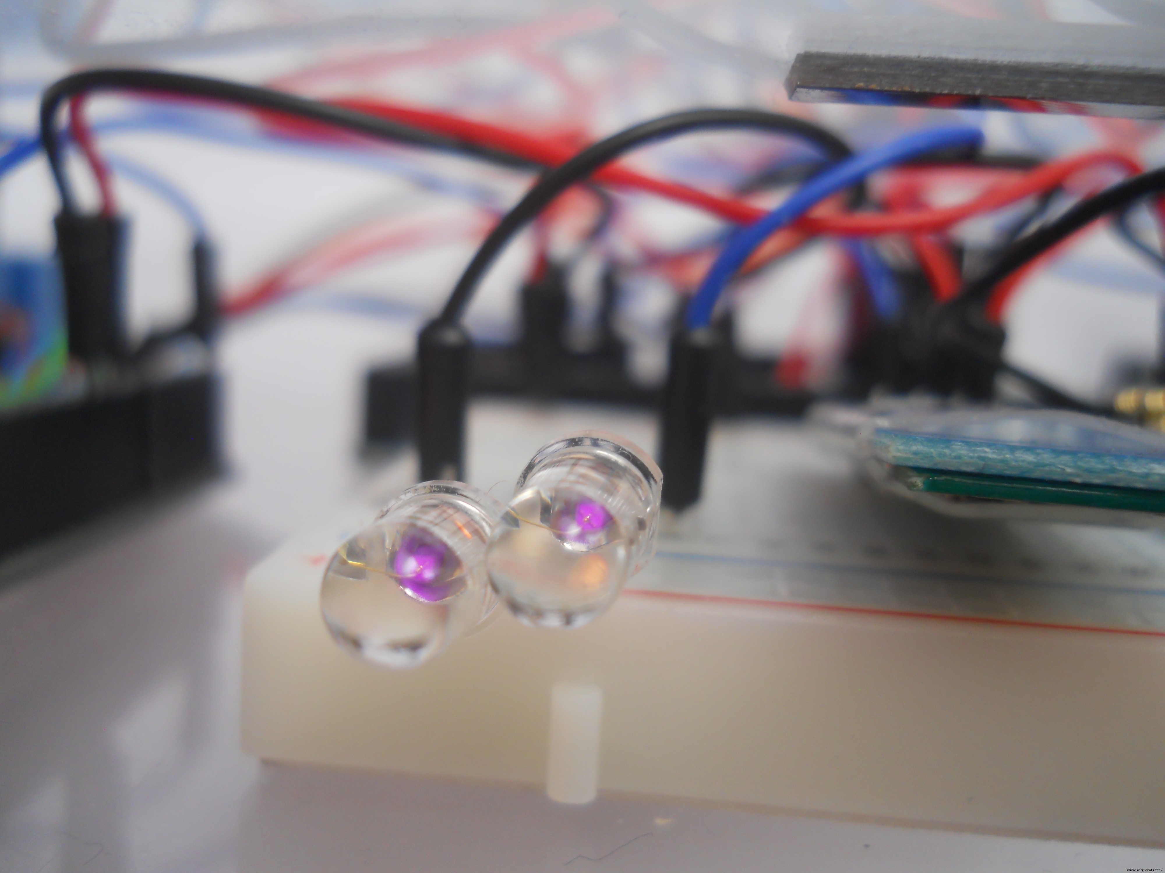
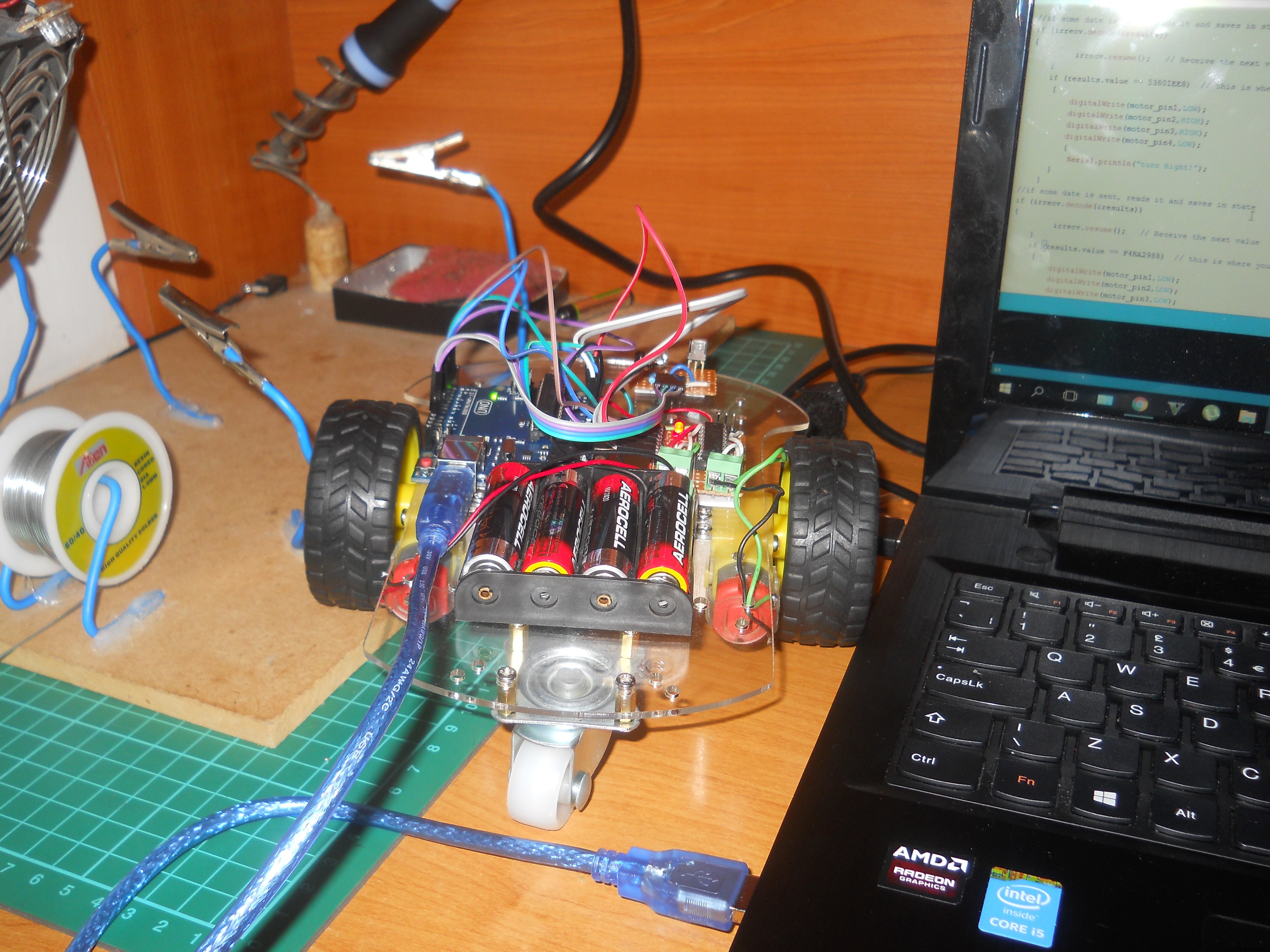
The IR Leds are connected to the digital pin D3 and with the IRremote library we send codes to the robot. It's pretty simple. The IR codes must be the same in the robot's code. If you think you're done you can test it with your camera. The infrared light looks purple on a photo, cameras can detect the IR light. This trick always works.
The Code
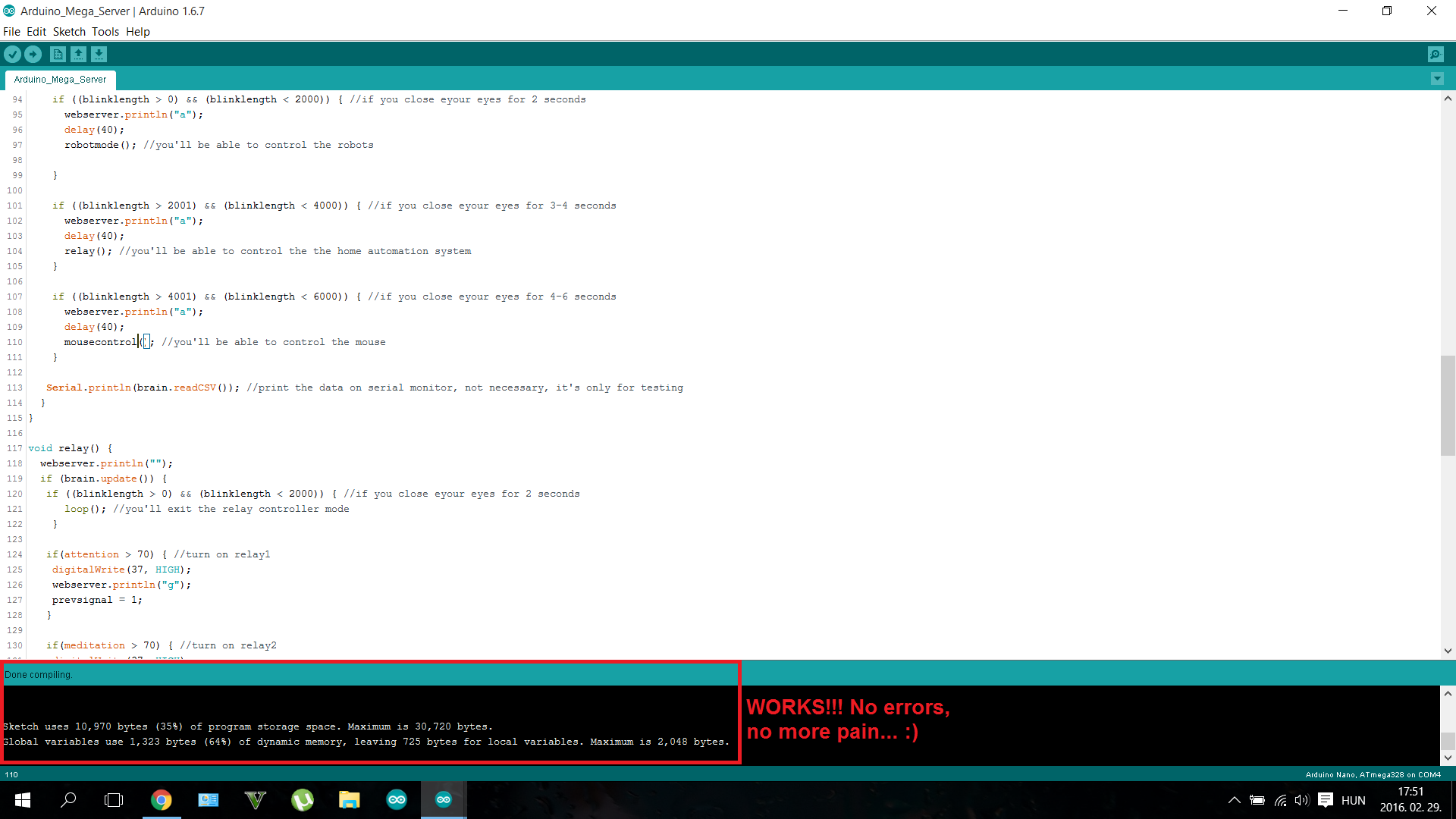
Use the "Arduino_Mega_Server" code in the Software part.
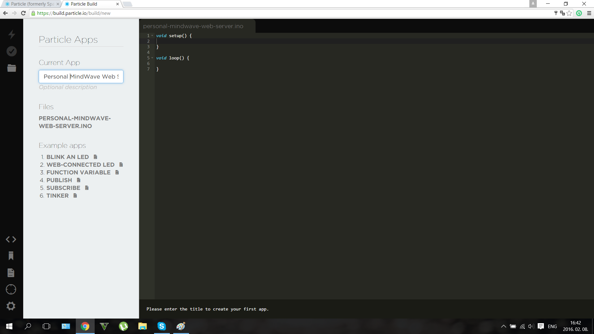
I suffered a lot while wrote the codes. I should program three different microcontrollers, so it was a big challenge. I used IRremote, Brain, SofwareSerial and Mouse libraries. (see download links at the Software part). But now the code is done and works so you just should upload to your microcontrollers. Download the .ino file or copy/paste the code in your IDE and use it. The code to the Particle Photon should be uploaded via the browser IDE. To make this register to the Particle Build. And connect your laptop to your microcontroller. I was really surprised that this happened almost automatically, I just added my Device ID number.

Before loading up the codes be sure nothing is connected to the RX/TX pins. So disconnect your BLuetooth module from the Mega, and disconnect the Mega from the Leonardo and the Photon.
The Mouse Controller
The Webserver
I wanted to add an IoT (Internet of Things) function in my project, so I made an online data logger using the Particle Photon. Depending on what you make with the device the Photon creates a personal server, and writes the data in the Cloud.
This may seem scary at first time, but imagine that you can detect if you are stressful (attention level increases and decreases quickly ) or if you should sleep (meditation level is always higher than 80) . This webserver may help you to live healthlier.
The Particle also has an online dashboard where you can publish any kind of data with the "Particle.publish();" syntax. We should have to say a big "thank you" for the developers of the dashboard. They saved a lot of time for us.
Writing codes in a browser?
It was intresting to write codes on a web page, but worked the same way like the normal IDE. The code was uploaded wirelessly. This microcontroller would be a very useful tool in everyone's toolbox.
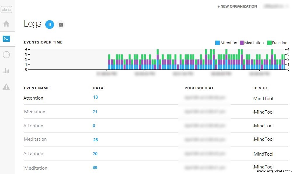
The dashboard looks somehow like this if you worked fine. Shows Attention and Meditation, and you can check them anytime, at your dashboard URL. For more info about the dashboards click here.
A quick upgrade for those who want to control only a robot with mindwaves:
You don't want to build the build the whole project, only a mindwave controlled robot? Don't worry if you're a beginner I thought even on you. I made a code with explanations that needs an Arduino Mini Pro and an IR LED and of course the headset to control the robot. I know that many of my readers wants to make a simple and fun weekend project so here's the description and the code for you.

Use the "RobotControlllerHeadset" code inthe Software section. Connect an IR LED to the D3 pin on the Mini Pro (Or Arduino UNO) and connect the T pin of the NeuroSky chip to the RX pin of the Arduino. Power up with 3.3 or 5 volts and you're done. So build the robot, then use this code in your headset:
#include #include #include IRsend irsend;Brain brain(Serial);const int ledPin =3; long interval =500; long previousMillis =0;int ledState =LOW; int medValue;void setup() { // Set up the LED pin. pinMode(ledPin, OUTPUT); // Start the hardware serial. Serial.begin(57600);}void loop() { // Expect packets about once per second. if (brain.update()) { Serial.println(brain.readCSV()); // Attention runs from 0 to 100. medValue =brain.readMeditation(); } // Make sure we have a signal. if(brain.readSignalQuality() ==0) { // Send a signal to the LED. if (medValue> 65) {irsend.sendNEC(0xFF10EF, 32); delay(40); } if (brain.readAttention()> 65) {irsend.sendNEC(0xFF18E7, 32); delay(40); } } }
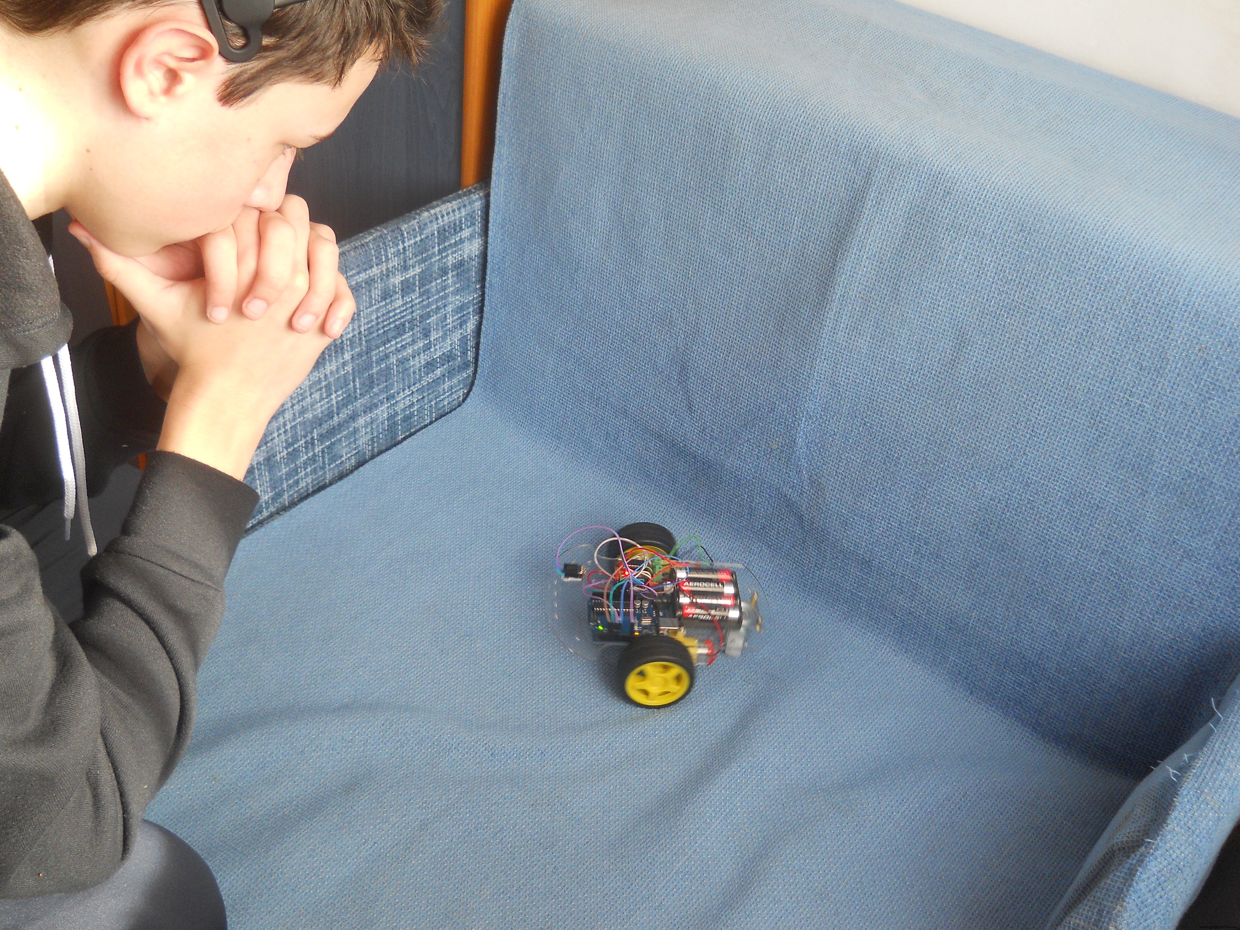
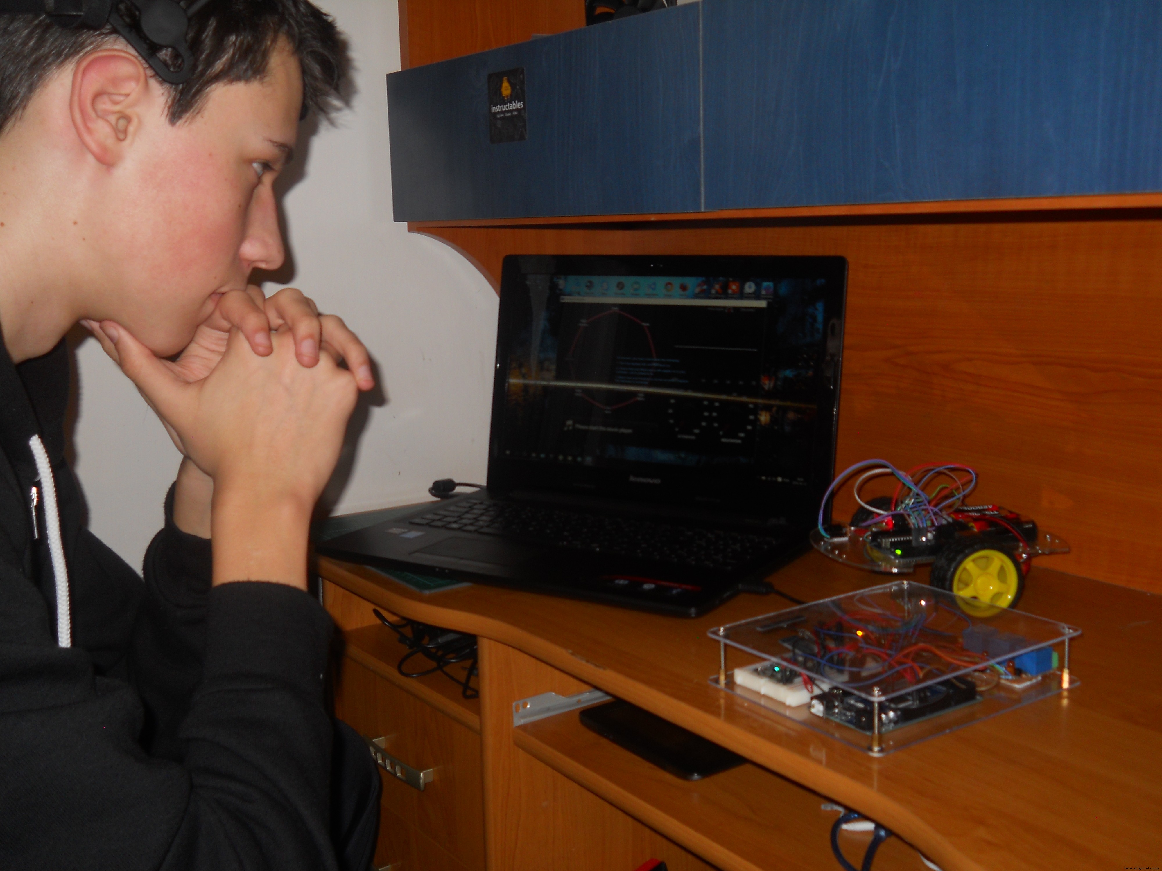
Becoming an IoT Jedi (Testing)
After making everything that I explained here, only one thing is left: try it out . Use the power of your mind, use the Force of the neurons in your brain, move your little robot, control your home, control everything with thoughts...
Now you become a real IoT Jedi!
The device has many features and it's very fun to play with. But as I said before it isn't only a toy , featuring biology and electronics we created a device that may help for people, who fight each day with their disabilities, to get back their natural capabilities.
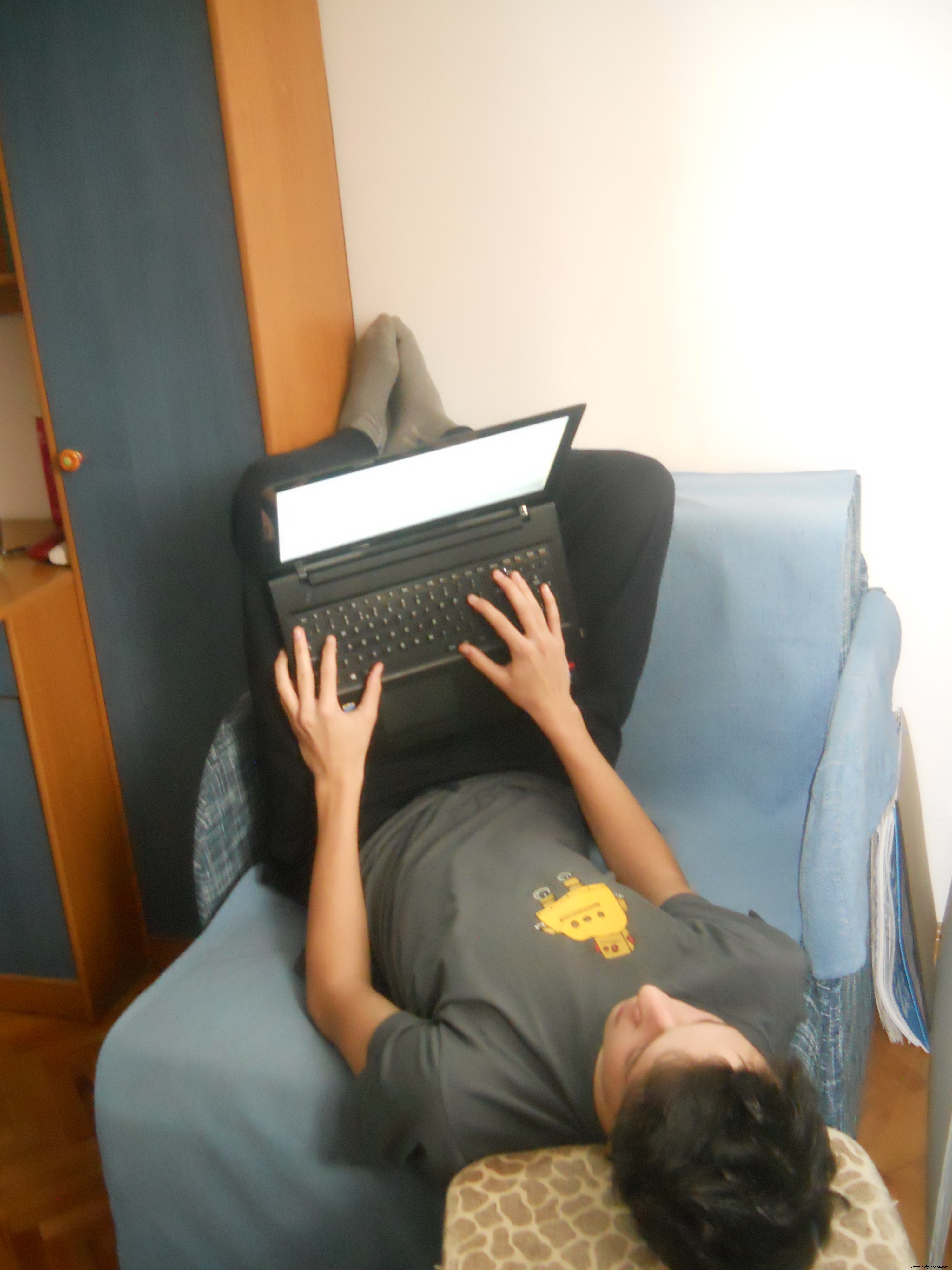
The robot can be controlled easily, the relays aren't big challange too. You only should learn how to control your attention levels to control the mouse. On the picture I'm trying to exit an app with my brainwaves. More practice guarantees better experience.
Thank you for watching!
I really hope that you liked my project and please write your opinion in comments. I wanted to make a video about the device, but coding was hard so I haven't enough time to make a short movie, but I'll publish it very soon on my Youtube channel and I'll update this project presentation too.
May the Force be with you, always!
<섹션 클래스="섹션 컨테이너 섹션 축소 가능" id="코드">//this is the code for the webserver for a "Use the Force... Or your Brainwaves?" project//creates a statistics for the user about his/her brainwaves meditation and attention level//thanked to the fully functioning dashboard of the Particle the code is very simpleint att;int med;int function;void setup() { Serial.begin(9600); }void loop() { // Publish data Spark.publish("Attention", (att) + "%"); 지연(2000); Spark.publish("Meditation", (med) + "%"); 지연(2000); Spark.publish("Last Function", (function) + ""); 지연(2000); if (Serial.available> 0) { char c =Serial.read(); } delay(10); switch(c) { case'a':att =10; 부서지다; case'b':att =20; 부서지다; case'c':att =30; 부서지다; case'd':att =40; 부서지다; case'e':att =50; 부서지다; case'f':att =60; 부서지다; case'g':att =70; 부서지다; case'h':att =80; 부서지다; case'i':att =90; 부서지다; case'j':att =100; 부서지다; case'k':med =10; 부서지다; case'l':med =20; 부서지다; case'm':med =30; 부서지다; case'n':med =40; 부서지다; case'o':med =50; 부서지다; case'p':med =60; 부서지다; case'q':med =70; 부서지다; case'r':med =80; 부서지다; case's':med =90; 부서지다; case't':med =100; 부서지다; case'x':function ="Home Automation" break; case'y':function ="Robot Controller Mode" break; case'z':function ="Mouse Controller" break; }} //Used for "Use the Force or your Brainwaves?" project#includeint IRpin =3;IRrecv irrecv(IRpin);decode_results results;int motor_pin1 =4;int motor_pin2 =5;int motor_pin3 =6;int motor_pin4 =7;void setup (){ irrecv.enableIRIn(); pinMode(motor_pin1,OUTPUT); pinMode(motor_pin2,OUTPUT); pinMode(motor_pin3,OUTPUT); pinMode(motor_pin4,OUTPUT); Serial.begin(9600);}void loop() { if (irrecv.decode(&results)) { irrecv.resume(); // Receive the next value } if (results.value ==0xFF18E7) //if gets this code goes forward { digitalWrite(motor_pin1,LOW); digitalWrite(motor_pin2,HIGH); digitalWrite(motor_pin3,LOW); digitalWrite(motor_pin4,HIGH); { Serial.println("Go Forward!"); } } if (irrecv.decode(&results)){ irrecv.resume(); // Receive the next value } if (results.value ==0xFF4AB5) //if gets this code goes backward { digitalWrite(motor_pin1,HIGH); digitalWrite(motor_pin2,LOW); digitalWrite(motor_pin3,HIGH); digitalWrite(motor_pin4,LOW); { Serial.println("Go Backward!"); } }if (irrecv.decode(&results)){ irrecv.resume(); // Receive the next value } if (results.value ==0xFF10EF) //if gets this code turns left { digitalWrite(motor_pin1,HIGH); digitalWrite(motor_pin2,LOW); digitalWrite(motor_pin3,LOW); digitalWrite(motor_pin4,HIGH); { Serial.println("Turn Left!"); } }if (irrecv.decode(&results)){ irrecv.resume(); // Receive the next value } if (results.value ==0xFF5AA5) //if gets this code turns right { digitalWrite(motor_pin1,LOW); digitalWrite(motor_pin2,HIGH); digitalWrite(motor_pin3,HIGH); digitalWrite(motor_pin4,LOW); { Serial.println("Turn Right!"); } }if (irrecv.decode(&results)){ irrecv.resume(); // Receive the next value } if (results.value ==0xFF38C7) //if gets this code stops { digitalWrite(motor_pin1,LOW); digitalWrite(motor_pin2,LOW); digitalWrite(motor_pin3,LOW); digitalWrite(motor_pin4,LOW); { Serial.println("Stop!"); } }}
// HC-05 configurationvoid setup() { // Start the hardware serial. Serial.begin(9600); // default HC-05 baud rate delay(1000); Serial.print("AT"); 지연(1000); Serial.print("AT+VERSION"); 지연(1000); Serial.println("AT+ROLE=1"); //set the HC-05 to master mode delay(1000); Serial.println(" AT+PAIR=copy here your adress,9"); //now the module should connnect automatically delay(1000); Serial.print("AT+BAUD7"); // Set baudrate to 576000 - eg Necomimi dafault Serial.begin(57600); // delay(1000);}void loop() {} //Code by Imets Tamas for the Use the Force... Or your Brainwaves? project//Moves the mouse cursor through serial signals#includevoid setup() { Serial.begin(9600); // initialize mouse control:Mouse.begin();}void loop() { // use serial input to control the mouse:if (Serial.available()> 0) { char inByte =Serial.read(); switch (inByte) { case 'u':// move mouse up Mouse.move(0, -8); 부서지다; case 'd':// move mouse down Mouse.move(0, 8); 부서지다; case 'l':// move mouse left Mouse.move(-8, 0); 부서지다; case 'r':// move mouse right Mouse.move(8, 0); 부서지다; case 'c':// perform mouse left click Mouse.click(MOUSE_LEFT); 부서지다; } }}
/* Arduino Mega Code for "A Tool for the Mind" project by Imets Tams, 2nd of February, 2016 This code analyzes and organizes then sends forward incoming bluetooth serial signals from the brainwave sensor Feel free to edit, but don't forget to credit, For the variable values I used the characters of family's name, you can change them if you want:I. M. E. T. S. See more details at http://www.instructables.com/member/Imetomi/ or https://www.hackster.io/Imetomi */#include// include the library #include // include the library #include // include the library #include // include the library #include int led =13;int medled =50; //the LED to shows the meditation levelint attled =51; //the LED to shows the attention levelint blinkled =52;char robot;IRsend irsend; //IR led to pin 3SoftwareSerial mouse(18, 19); //RX, TX this goes to the Leaonardo BoardSoftwareSerial webserver(16, 15); //goes to the Particle Photon to create a web serverLiquidCrystal lcd(12, 11, 5, 4, 3, 2); // initialize the library with the numbers of the interface pinsBrain brain(Serial); //the Brainwaves are read with the help of the bluetooth module through hardware serialint closedeye =(brain.readLowAlpha()); //to detect blinkint attention =(brain.readAttention()); //to read attentionint brainsignal =(brain.readSignalQuality()); //to read signal qualityint meditation =(brain.readMeditation()); //to detect meditationint alpha =(brain.readHighAlpha()); //to detect closed eyeint lightatt;int lightmed;int blinklength;int prevsignal =0;void setup() { //here we're going to set the main settings:mouse.begin(9600); //set the baud rate webserver.begin(9600); //set the baud rate Serial.begin(57600); //set the baud rate (57600 is the Necomimi's bit/seconds rate) lcd.begin(16, 2); //start the LCD screen pinMode(led, OUTPUT); //set pinmodes for the leds and relays pinMode(attled, OUTPUT); //set pinmodes for the leds and relays pinMode(medled, OUTPUT); //set pinmodes for the leds and relays pinMode(blinkled, OUTPUT); //set pinmodes for the leds and relays pinMode(37, OUTPUT); //set pinmodes for the leds and relays pinMode(38, OUTPUT); //set pinmodes for the leds and relays pinMode(39, OUTPUT); //set pinmodes for the leds and relays lightatt =map(attention, 0, 100, 0, 255); //map the attention level for analogWrite the LED lightmed =map(meditation, 0, 100, 0, 255); //map the attention level for analogWrite the LED}void robotmode() { if (brain.update()) { if ((blinklength> 0) &&(blinklength <2000)) { //if you close eyour eyes for 2 seconds loop(); //you'll exit the robot controller mode } if (attention> 70) { irsend.sendNEC(0xFF18E7, 32); //go forward webserver.println("g"); delay(40); } if (meditation> 70) { irsend.sendNEC(0xFF10EF, 32); //spin webserver.println("q"); delay(40); } }}void loop() { if (brain.update()){ analogWrite(attled, lightatt); //analog write the attention led to show the actual attention level //the more focused you are, the stronger thee LED lights analogWrite(medled, lightmed); //analog write the attention led to show the actual attention level //the higher meditation level will light up the LED if ((closedeye> 30000) &&(alpha> 30000)) { //we use 2 values to be sure the user's eye is closed digitalWrite(blinkled, HIGH); //in english:if eyes are closed the LED will light up blinklength =millis(); // count milliseconds if eye closed } else if ((closedeye <30000) &&(alpha <30000)) { digitalWrite(blinkled, LOW); //in english:if eyes are opened the LED will turn off blinklength =0; } if ((blinklength> 0) &&(blinklength <2000)) { //if you close eyour eyes for 2 seconds webserver.println("a"); delay(40); robotmode(); //you'll be able to control the robots } if ((blinklength> 2001) &&(blinklength <4000)) { //if you close eyour eyes for 3-4 seconds webserver.println("a"); delay(40); relay(); //you'll be able to control the the home automation system } if ((blinklength> 4001) &&(blinklength <6000)) { //if you close eyour eyes for 4-6 seconds webserver.println("a"); delay(40); mousecontrol(); //you'll be able to control the mouse } Serial.println(brain.readCSV()); //print the data on serial monitor, not necessary, it's only for testing }}void relay() { webserver.println(""); if (brain.update()) { if ((blinklength> 0) &&(blinklength <2000)) { //if you close eyour eyes for 2 seconds loop(); //you'll exit the relay controller mode } if(attention> 70) { //turn on relay1 digitalWrite(37, HIGH); webserver.println("g"); prevsignal =1; } if(meditation> 70) { //turn on relay2 digitalWrite(37, HIGH); webserver.println("q"); prevsignal =1; } if(1000> blinklength> 0) { //turn on relay3 digitalWrite(37, HIGH); webserver.println("qj"); prevsignal =1; } if((attention> 70) &&(prevsignal ==1)) { digitalWrite(37, LOW); webserver.println("q"); prevsignal =1; //check if is already turned on, then turn off } if((meditation> 70) &&(prevsignal ==1)) { digitalWrite(37, LOW); webserver.println("qj"); prevsignal =1; //check if is already turned on, then turn off } if((1000> blinklength> 0) &&(prevsignal ==1)) { digitalWrite(37, LOW); webserver.println("a"); prevsignal =1; //check if is already turned on, then turn off } }}void mousecontrol() { //you'll need a few hours of practice to control the cursor perfectly webserver.println("z"); //forward data to the webserver if(brain.update()) { if (0 70) { mouse.println('c'); //click webserver.println("t"); } }}
#include#include #include IRsend irsend;Brain brain(Serial);const int ledPin =3; long interval =500; long previousMillis =0;int ledState =LOW; int medValue;void setup() { // Set up the LED pin. pinMode(ledPin, OUTPUT); // Start the hardware serial. Serial.begin(57600);}void loop() { // Expect packets about once per second. if (brain.update()) { Serial.println(brain.readCSV()); // Attention runs from 0 to 100. medValue =brain.readMeditation(); } // Make sure we have a signal. if(brain.readSignalQuality() ==0) { // Send a signal to the LED. if (medValue> 65) {irsend.sendNEC(0xFF10EF, 32); delay(40); } if (brain.readAttention()> 65) {irsend.sendNEC(0xFF18E7, 32); delay(40); } } }
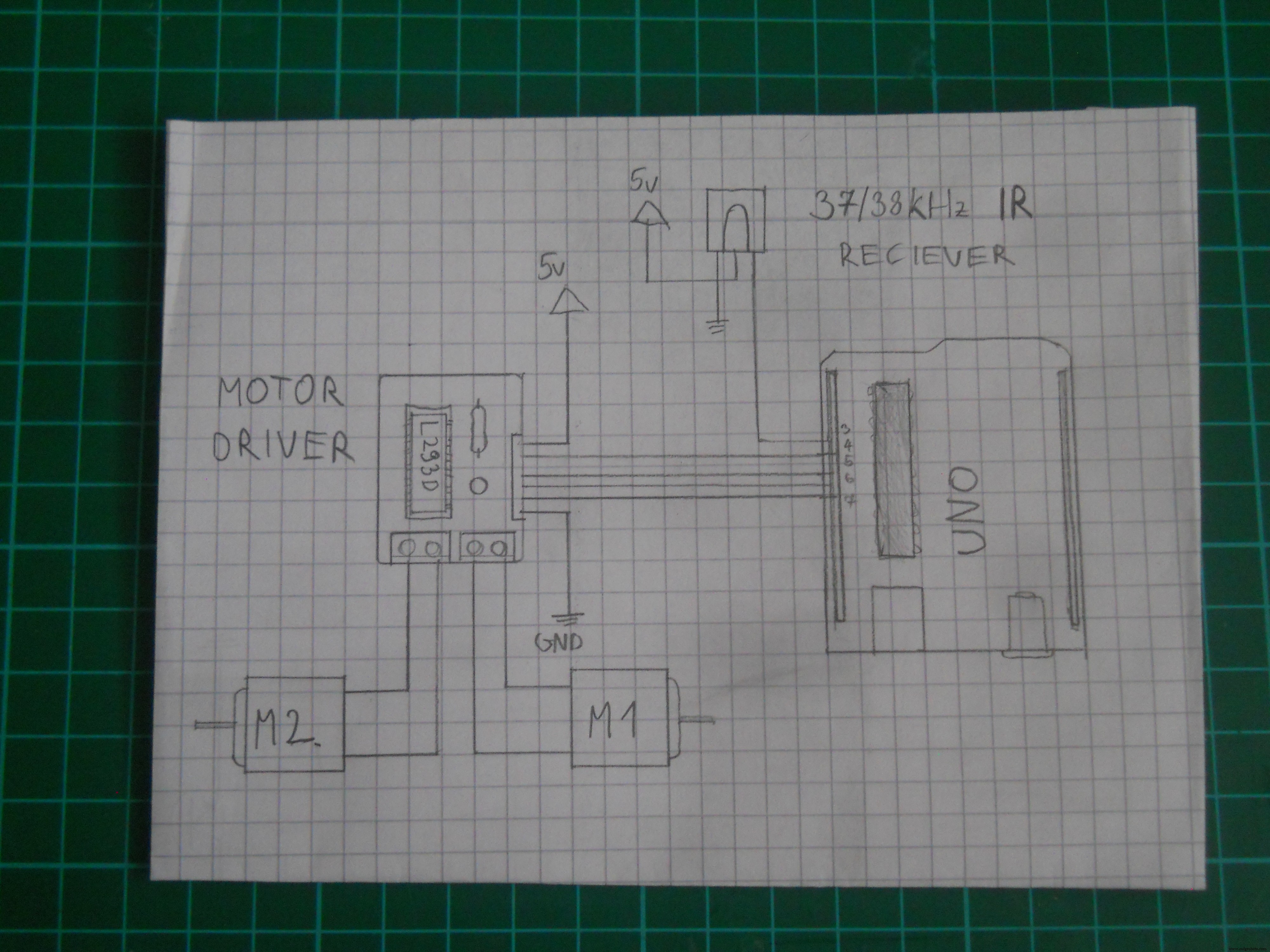
 Schematic for the DIY IR robot
 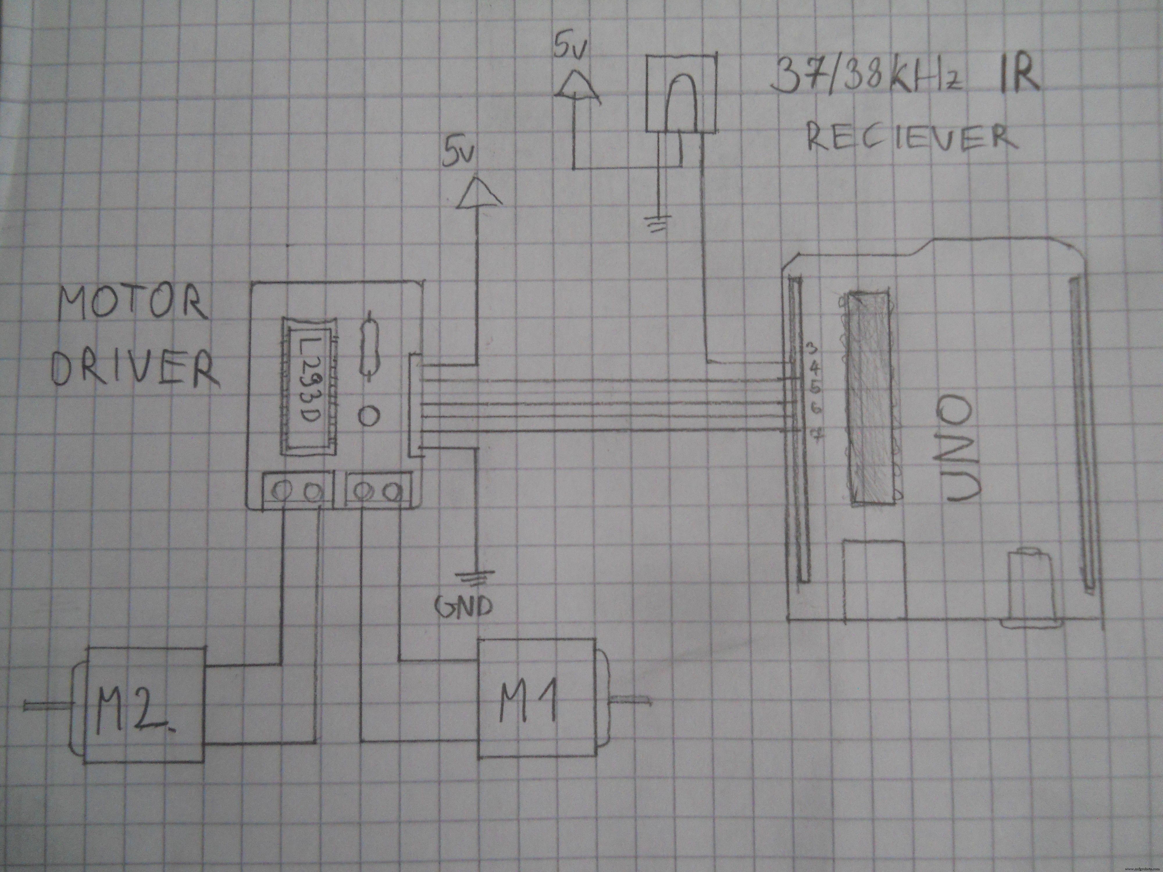 Schematic for the DIY 3 channel relay module. Used Arduino pins:D37, D38, D39.
 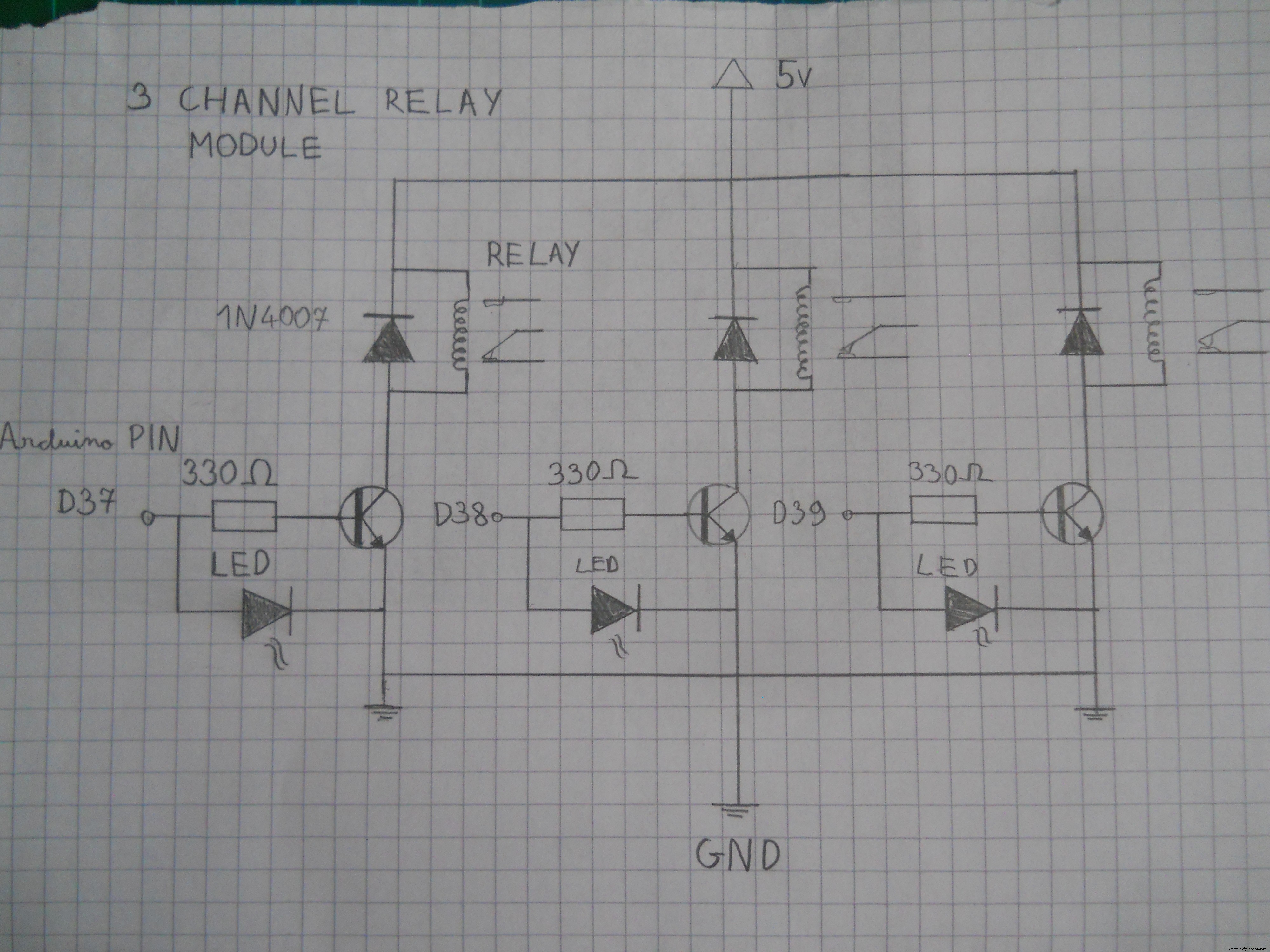 Schematic for the motor driver. Connect the pins to the Arduino.
  Schematic for the main server's electronics.
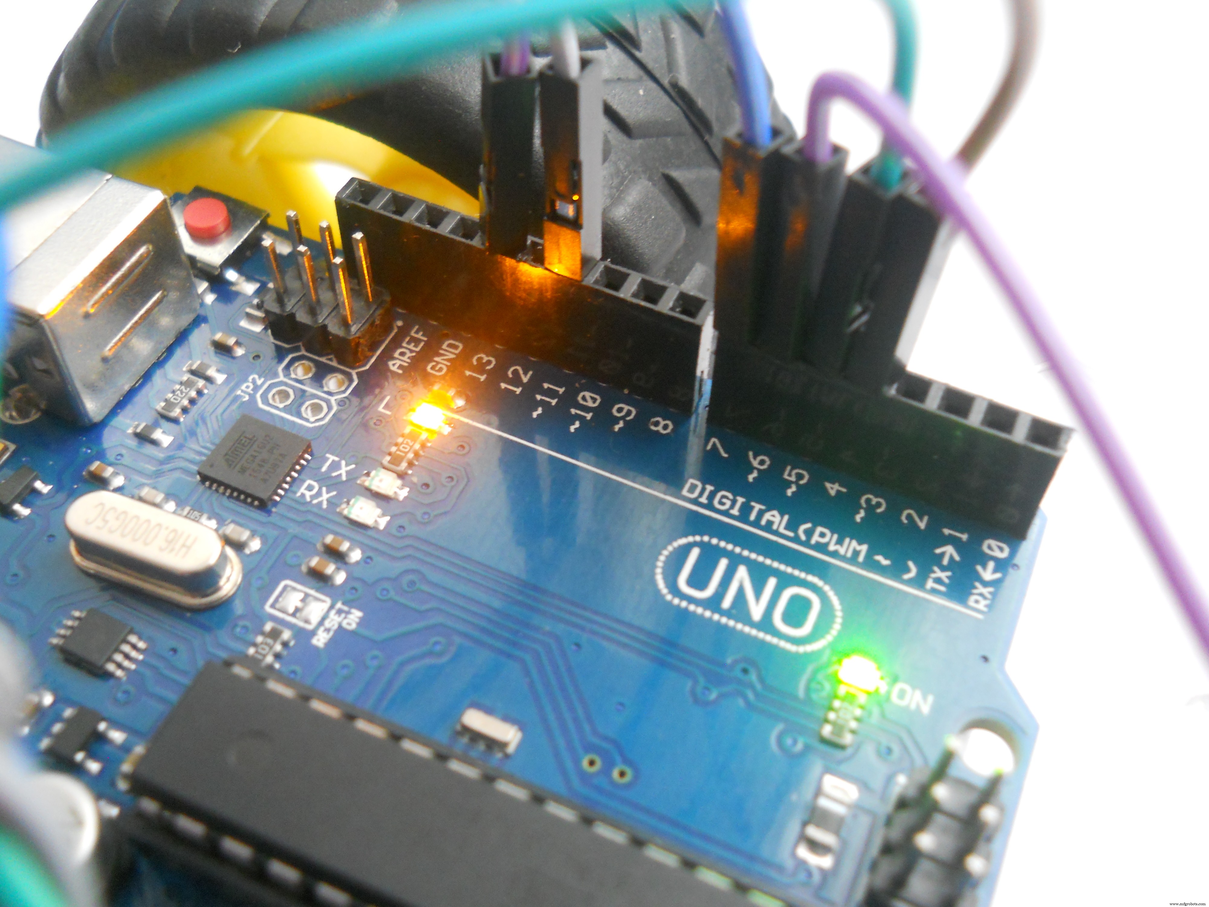
  Schematic for the Arduino UNO robot
 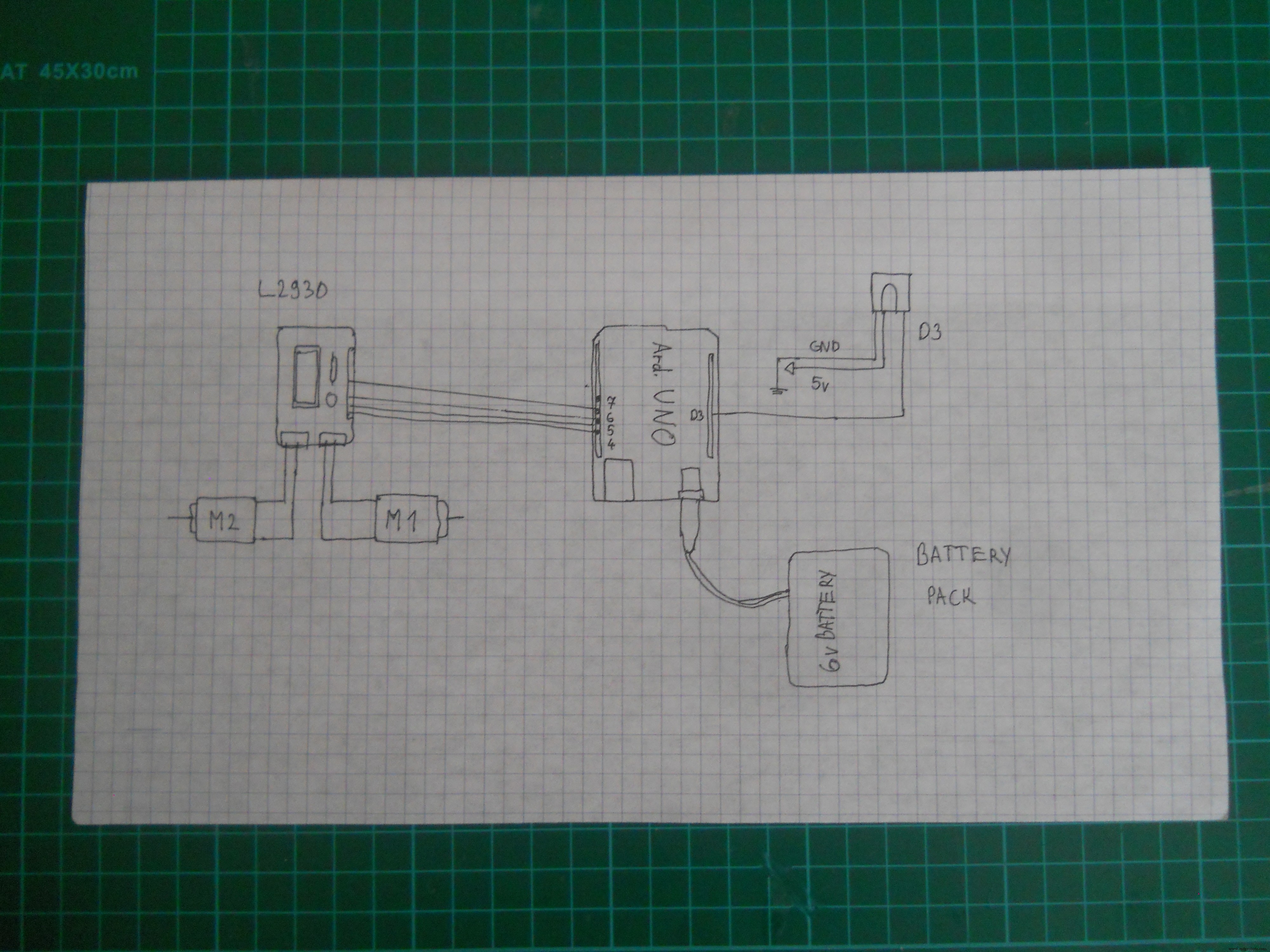 Schematic for the IR robot
  Use this schematic to make the main server.
 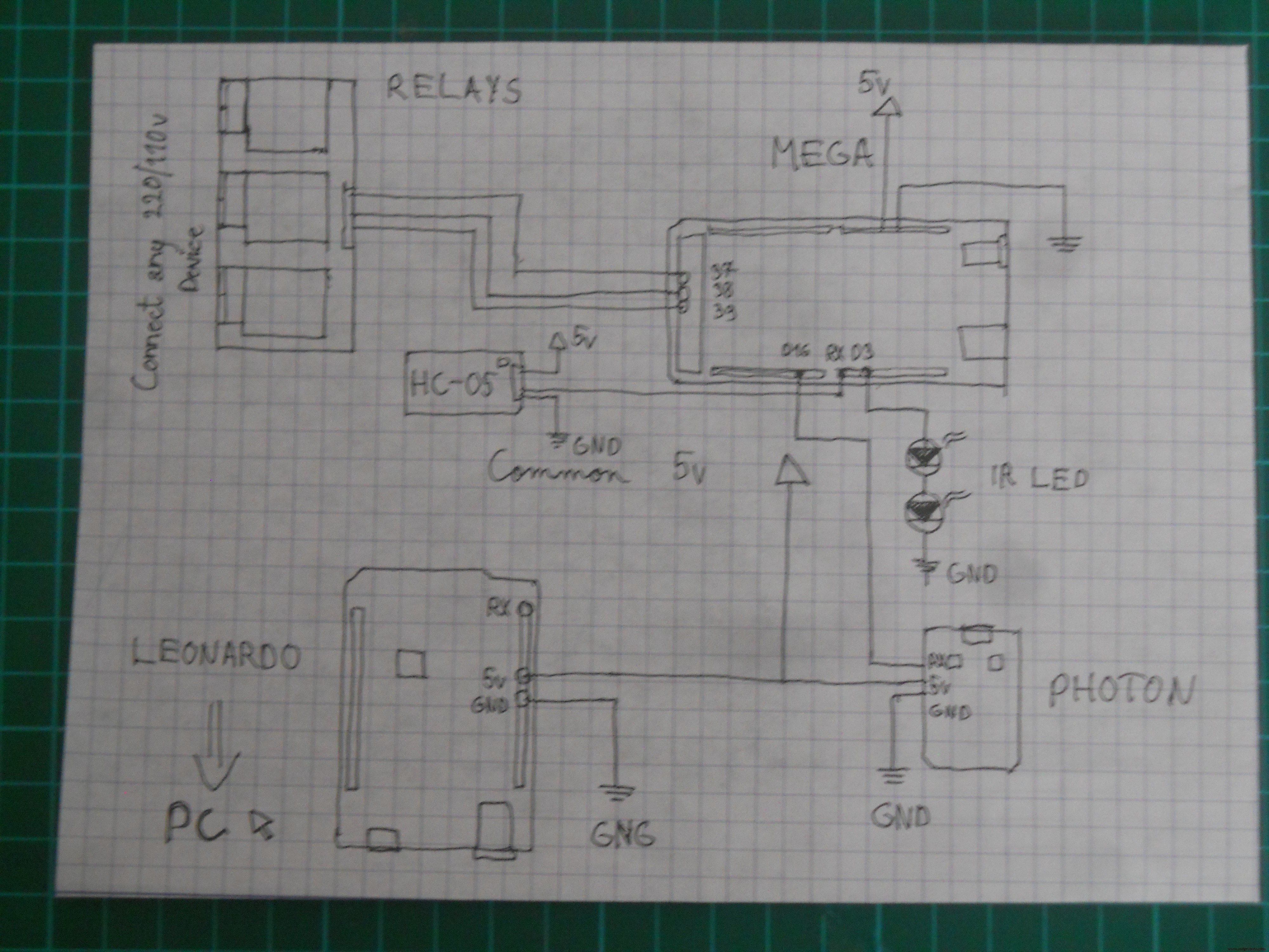 Schematic for the headset's electronics
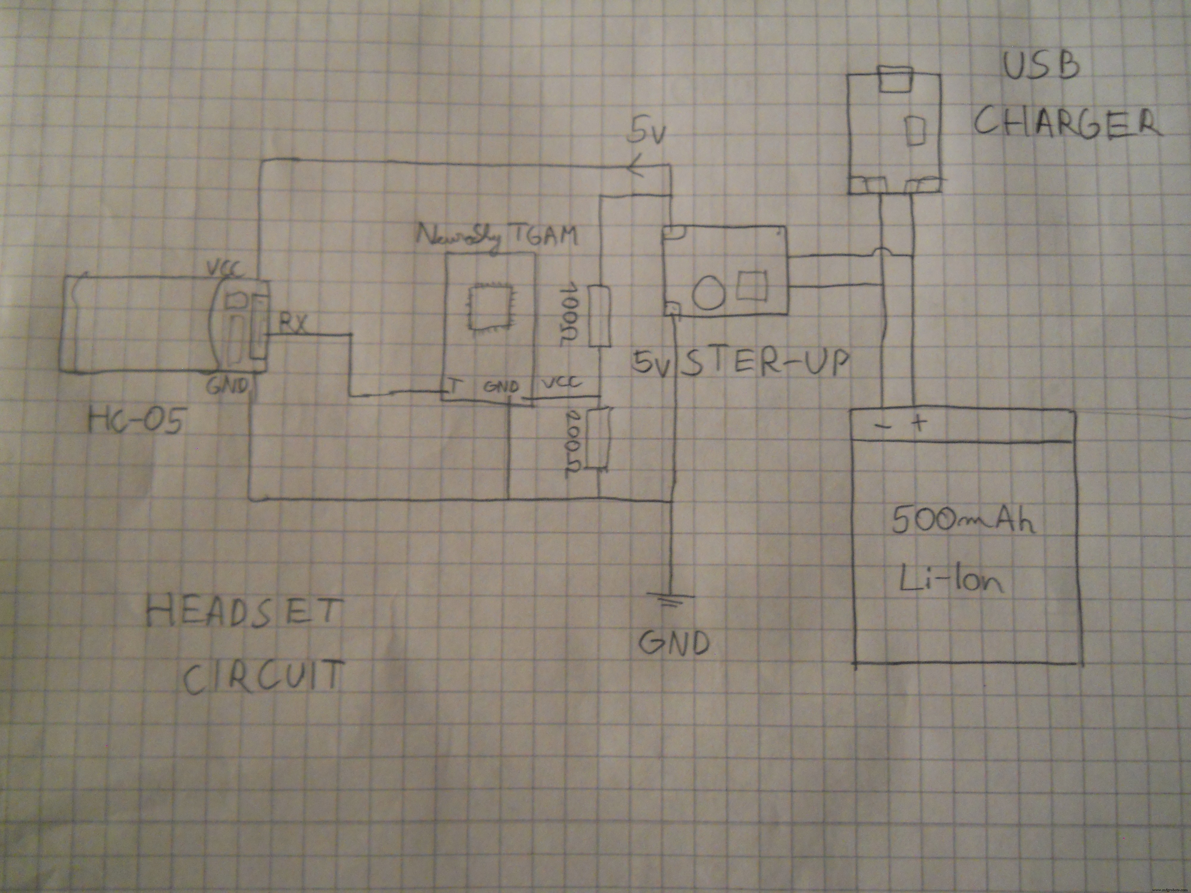
제조공정
Arduino 자습서 시리즈의 네 번째 Arduino 자습서에 오신 것을 환영합니다. 이 튜토리얼에서는 PWM(Pulse Width Modulation)을 사용하여 DC 및 서보 모터를 제어하는 방법을 배웁니다. 이것은 따라하기 쉬운 단계별 비디오 자습서입니다. 또한 동영상 아래에서 이 튜토리얼에 필요한 부품과 동영상의 예제 소스 코드를 찾을 수 있습니다. 첫 번째 예에 필요한 구성요소 DC 모터 ........................................................... 또는 CPU 팬
스테퍼 모터는 정확한 위치 제어를 달성하기 위해 전체 회전을 동일한 단계로 나눕니다. 오늘의 토론 주제는 28BYJ-48 단극 8비트 4상 영구 자석 구동 스테퍼 모터입니다. 프로젝트를 진행 중이고 사용하기 쉬운 모터가 필요하다고 가정해 보겠습니다. 28BYJ-48이 적합합니다. 또한 Arduino와 페어링할 수 있는 가장 저렴한 스테퍼 모터 중 하나입니다. 이 스테퍼 모터의 작동을 더 잘 이해하려면 계속 읽으십시오. 28BYJ-48이란 무엇입니까? 그림 1:28BYJ-48 스테퍼 모터 28BYJ-48은 5개의 단자