오늘은 인터넷에 연결하여 사용자가 Wi-Fi를 통해 원격으로 집을 제어할 수 있는 장치를 구축할 것입니다. 우리는 이 장치를 만들기 위해 ESP8266-01 와이파이 모듈과 함께 Arduino 보드(모든 모델이 잘 작동합니다)를 사용할 것입니다. 시작하겠습니다!
스마트 홈이란 무엇입니까?
작업 시나리오
제어판
우리는 사용자가 우리 시스템에 연결된 모든 가전 제품을 제어할 수 있도록 하는 제어판으로 작동할 간단한 웹 페이지를 구축할 것입니다. 웹 페이지를 구축하기 위해 다음을 사용할 것입니다:
<울>
HTML
CSS
제이쿼리
내장 하드웨어
웹 페이지는 Arduino 보드에 연결된 웹 서버로 작동하는 ESP8266-01에 몇 가지 주문을 보냅니다. 그리고 들어오는 데이터에 따라 Arduino 보드는 전구 켜기, TV 끄기와 같은 몇 가지 작업을 수행하며 이 부분에서는 다음을 사용합니다.
<울>
아두이노
ESP8266-01
ESP8266-01 시작하기
앞서 말했듯이 인터넷에 연결하려면 Arduino 보드가 필요하지만 현재 사용 중인 Arduino Nano 버전에는 해당 기능이 없습니다. 따라서 ESP8266-01 Wi-Fi 모듈을 사용하여 우리의 작은 Arduino 보드에 Wi-Fi 기능을 추가합니다.
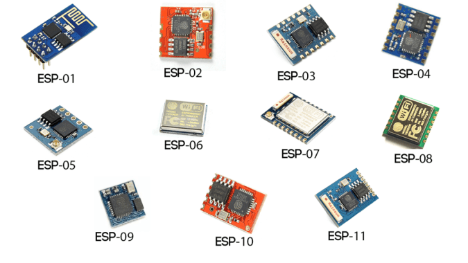
ESP wifi 모듈 모델이 많이 있는데 어떤 모델을 선택해야 하나요? 음, 거의 모든 ESP 제품군 Wi-Fi 모듈이 잘 작동하지만 각각 고유한 기능과 사양이 있습니다. 각각의 사양과 기능을 살펴보고 필요에 가장 적합한 것을 선택하는 것이 좋습니다.
내 필요에 따라 ESP8266-01이 가장 적합한 것으로 나타났으며 여러 가지 이유가 있습니다. 메이커 커뮤니티에서 매우 유명합니다. 그 결과, 이 멋진 작은 모듈로 직면하는 거의 모든 질문이나 문제에 대한 답을 찾을 수 있는 매우 견고한 온라인 커뮤니티가 생겼습니다. 또한 가격도 매우 저렴합니다(약 1.5$).
또한, 시리얼 통신을 통해 아두이노 보드와 통신할 수 있는 시리얼 와이파이 모듈로 아두이노 보드와 함께 사용하기 매우 쉽습니다. 마이크로컨트롤러가 내장되어 있어 독립형 마이크로컨트롤러와 Wi-Fi 모듈을 하나의 콤보로 사용할 수 있어 매우 좋습니다. 2개의 GPIO가 내장되어 있습니다. 1.5$만 있으면 이 모든 기능을 사용할 수 있습니다. 이 기능은 실제로 매우 훌륭합니다. 이 모듈을 자세히 살펴보겠습니다.
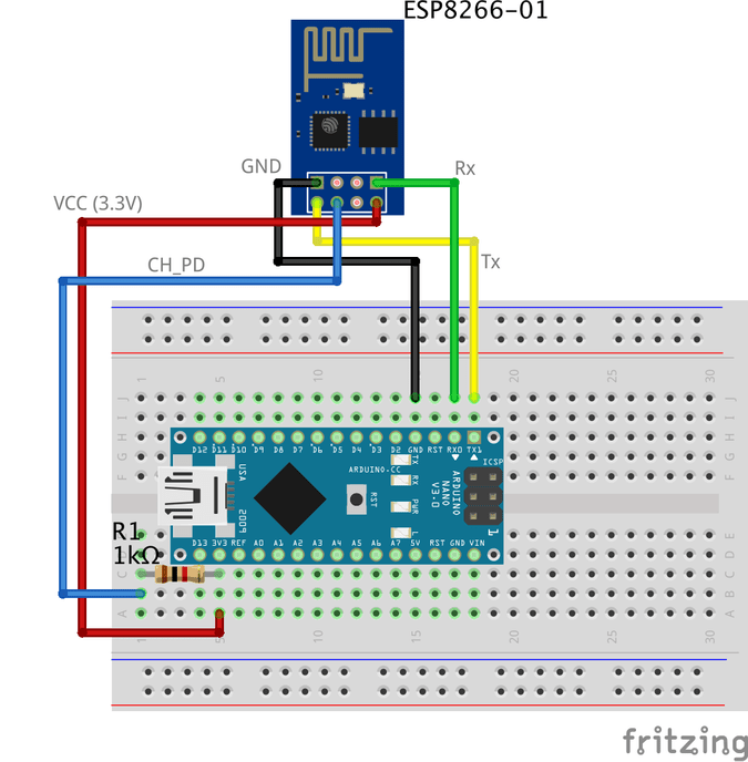
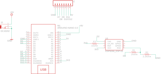
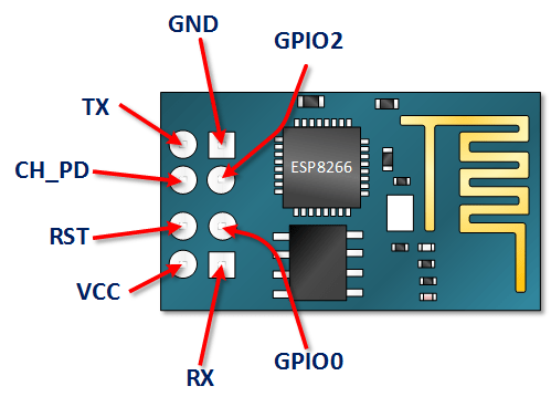
ESP8266-01 핀아웃 <울>
VCC: +3.3V 전원에 연결합니다. 5V 소스에 연결하지 마세요. 손상될 수 있습니다. .
GND: -ve 핀, 회로의 접지에 연결합니다.
CH_PD: 칩 인에이블 핀 – Active HIGH. 모듈을 부팅할 수 있도록 논리 값 HIGH에 연결합니다.
RST: 칩 리셋 핀 - 활성 LOW, LOW로 당겨지면 모듈을 리셋합니다.
GPIO0, GPIO2: 범용 입력/출력 핀.
송신: 마이크로 컨트롤러(Arduino)의 Rx에 연결하여 직렬 통신을 설정합니다.
수신: 마이크로 컨트롤러(Arduino)의 Tx에 연결하여 직렬 통신을 설정합니다.
ESP8266-01 구성
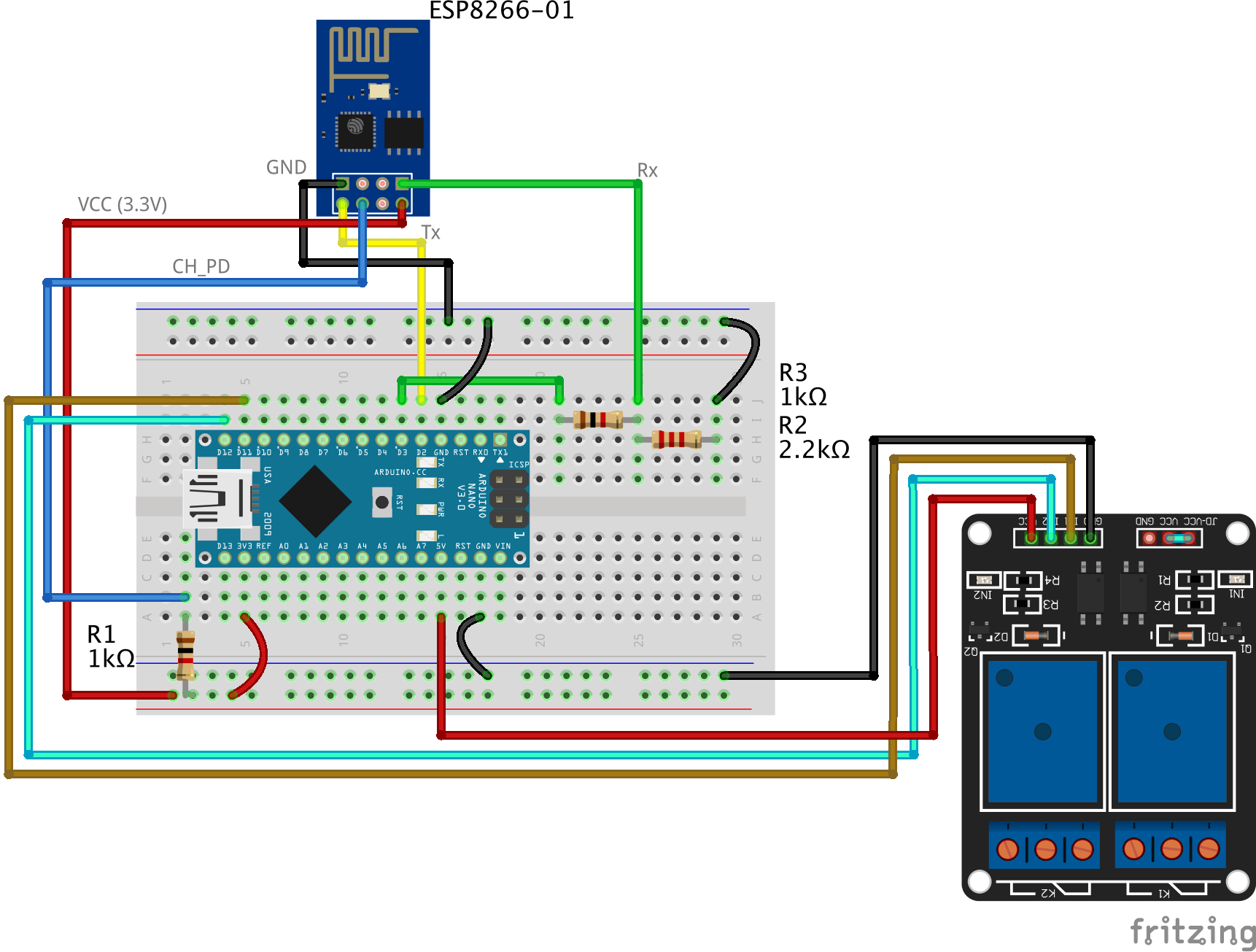
ESP8266-01 모듈은 직렬 통신을 통해 Arduino 보드와 통신하기 전에 언급했듯이 Arduino의 직렬 핀 0, 1(Tx, Rx)과 연결해야 합니다. 그러나 여기서 문제는 디버깅 목적으로 ESP8266-01과 함께 Arduino 직렬 모니터를 사용하기 때문에 이 핀이 사용 중이라는 것입니다. 따라서 ESP8266-01과 함께 사용하려면 다른 두 개의 직렬 통신 핀을 찾아야 합니다.
다행히 Arduino는 이것을 쉽게 만들었습니다. 소프트웨어를 사용하여 기능을 복제하여 Arduino의 다른 디지털 핀에서 직렬 통신을 허용하도록 개발된 "SoftwareSerial"이라는 라이브러리가 있습니다. 예를 들어 이 라이브러리를 사용하여 핀 2, 3(SoftwareSerial)을 핀 0, 1(하드웨어 직렬)과 함께 Rx 및 Tx로 설정할 수 있습니다.
"소프트웨어 직렬" 라이브러리는 전송 속도가 19,200보드 미만인 한 잘 작동합니다. 하지만, 여기에 작은 문제가 있습니다! ESP8266-01 와이파이 모듈은 "SoftwareSerial" 라이브러리에서 통신하기 어려운 115, 200 보드 속도로 통신하도록 공장에서 프로그래밍된 상태로 제공됩니다. 따라서 "SoftwareSerial" 라이브러리와 매우 잘 작동하는 통신 속도를 9600 보드로 설정하기 위해 Wi-Fi 모듈을 다시 프로그래밍해야 합니다. 이를 위해 일부 "AT 명령"을 사용할 것입니다.
ESP8266-01 통신 속도 변경
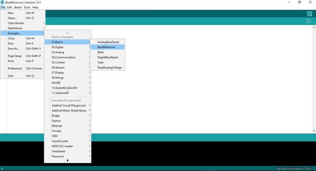
첫 번째 단계:Arduino 보드에 빈 프로그램 업로드
이 단계에서는 빈 코드를 Arduino 보드에 업로드합니다. Arduino 보드에 의해 백그라운드에서 실행 중인 것이 없는지 확인하십시오.
두 번째 단계:Arduino 보드와 ESP8266-01 연결
ESP8266-01을 재구성하고 통신 속도(전송 속도)를 변경하려면 AT 명령을 사용합니다. 간단히 말해서, AT 명령은 모뎀, 휴대폰, 블루투스 모듈, 와이파이 모듈, GSM 모듈을 제어하는 데 사용되는 몇 가지 명령입니다.
이 명령을 사용하면 제조업체 이름, 모델 번호, IMEI 등과 같은 휴대폰 또는 GSM 모듈에 대한 기본 정보를 얻을 수 있습니다. "AT"는 "ATtention"의 약어이며 모든 명령이 시작되기 때문에 AT 명령이라고 합니다. "AT"로. "AT" 접두사는 명령 자체의 일부가 아니며 모듈에 명령의 시작을 알려줍니다.
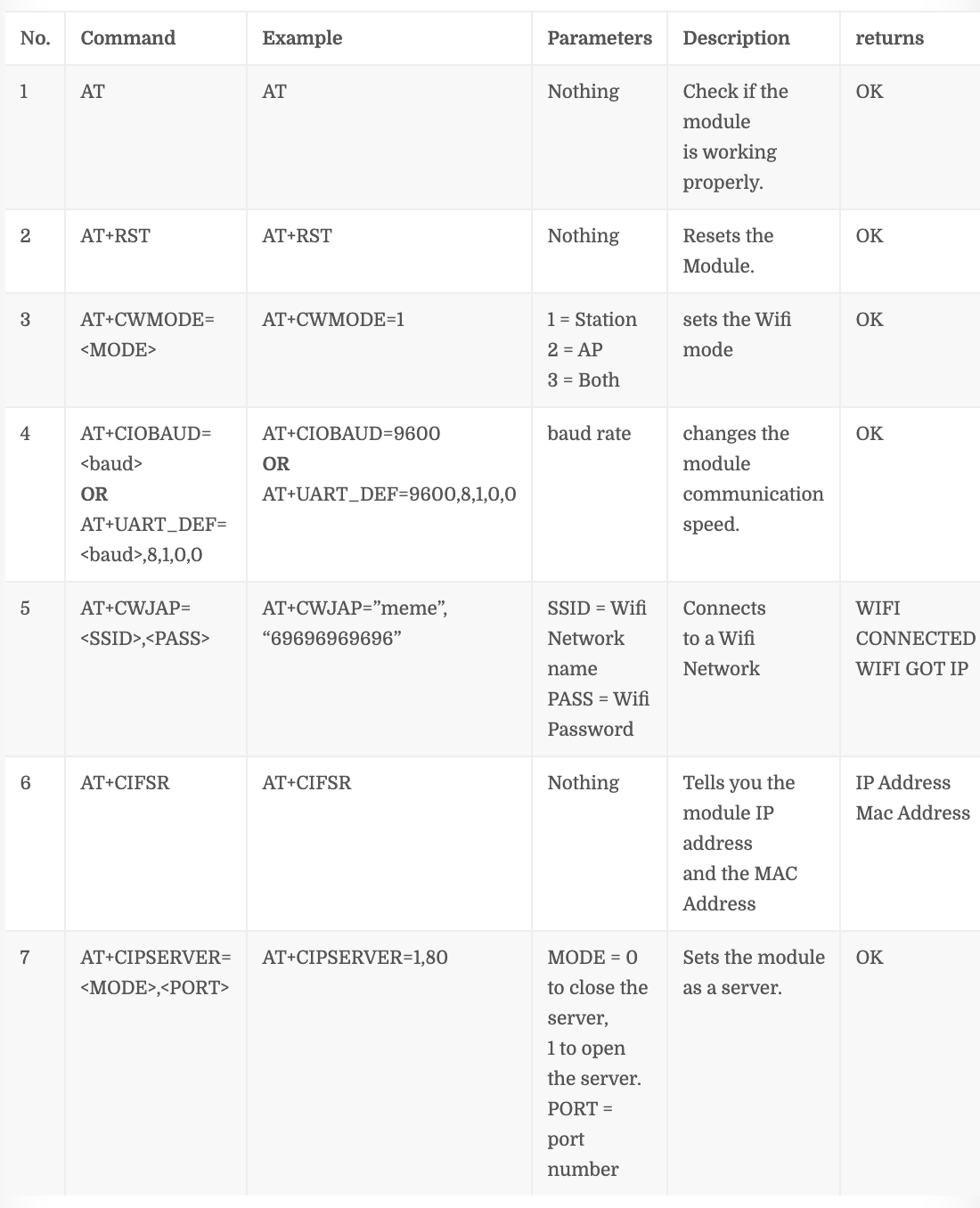
몇 가지 중요한 AT 명령
명령 번호 “4” 이 명령이 작동하지 않는 경우 ESP8266-01 펌웨어 버전에 따라 다릅니다. AT+CIOBAUD=AT+UART_DEF=,8,1,0,0을 사용해 보세요.
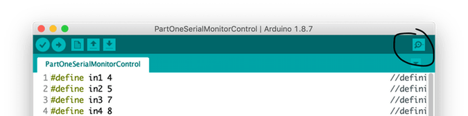
1단계:직렬 모니터 열기
2단계:통신 속도를 115, 200보드로 설정
앞서 언급했듯이 ESP는 115, 200보드의 속도로 통신하도록 프로그래밍된 제조업체에서 제공합니다. 따라서 Arduino 통신 속도를 115, 200으로 설정해야 합니다. 그것도 처음으로 만 나중에 우리가 그것을 변경할 것입니다. 또한 'NL 및 CR 모두'를 선택해야 합니다. .
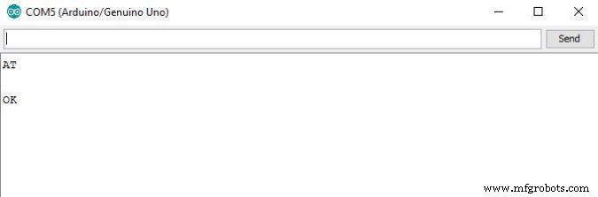
3단계:'AT'를 보내고 ESP 모듈이 사용자의 말을 듣고 있는지 응답을 기다립니다.
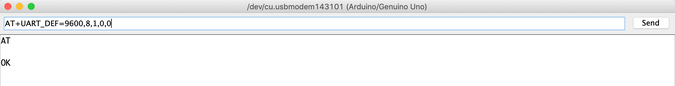
4단계:이제 ESP8266-01 통신 속도를 변경합니다.
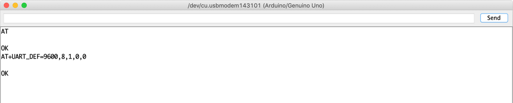
내 ESP8266-01 모듈 로드 펌웨어는 1.6입니다. 이 명령은 AT+UART_DEF=,8,1,0,0 나를 위해 잘 작동합니다. 작동하지 않으면 AT+CIOBAUD=를 시도하십시오. . "확인"으로 응답하는 경우 이제 ESP 모듈 통신 전송 속도가 115, 200에서 변경되었습니다. baud to 9600 보오드. 축하 해요!
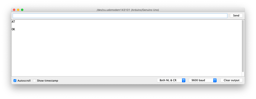
시리얼 모니터 통신 속도를 다시 9600으로 변경하고 "AT"를 다시 보내 ESP 모듈이 새로운 속도(9600)에서 우리의 말을 들을 수 있는지 확인합니다.
바라보다! 작동 중입니다. ESP8266-01은 이제 115, 200 전송 속도 대신 9600 전송 속도에서 Arduino 보드와 통신할 수 있습니다.
이제 Wi-Fi 네트워크에 연결해 보겠습니다.
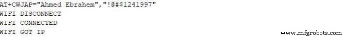
Enter 키를 누르면 ESP8266-01이 이 네트워크를 검색하여 연결합니다. 프로세스가 성공하면 이
를 반환합니다.
와이파이 연결
WIFI GOT IP
이 시점에서 ESP8266-01 통신 속도를 115, 200 baud에서 9600 baud로 성공적으로 변경했습니다. 이제 사용자가 가전 제품을 제어하는 데 사용할 제어판(웹 페이지)을 빌드해야 합니다. 자, 이제 만들어 봅시다!
인터넷이란 무엇입니까?
사실, 인터넷은 땅 속에 묻힌 전선입니다. 광섬유, 구리 또는 위성일 수도 있지만 인터넷은 단순한 전선입니다. 그 전선에 연결된 두 대의 컴퓨터는 통신할 수 있습니다. 컴퓨터가 직접 연결된 경우 해당 회선에 서버라고 합니다. 해당 회선에 직접 연결되지 않은 경우 클라이언트라고 합니다. .
서버: Apache와 같은 특정 운영 체제를 실행하는 특수 컴퓨터입니다. 이 특수 컴퓨터는 디스크 드라이브에 일부 웹 페이지, 파일, 데이터베이스를 저장합니다. 인터넷에 연결된 모든 서버에는 172.217.171.228과 같은 고유한 IP 주소가 있습니다. , IP 주소는 사람들이 서로를 쉽게 찾을 수 있도록 도와주는 전화번호와 같습니다. 그 IP 주소는 사람이 기억하기 쉽지 않기 때문입니다. 그래서 이름을 google.com으로 지정했습니다. (도메인 이름).
고객: 여러분과 제가 매일 사용하는 것과 같은 컴퓨터로, 인터넷 서비스 제공자(ISP)를 통해 간접적으로 인터넷에 연결되고 고유한 IP 주소도 가지고 있습니다.
작업 시나리오
간단히 말해서 google chrome, firefox와 같은 웹 브라우저(클라이언트)에서 보낸 요청으로 시작하여 웹 서버에서 받은 응답으로 끝납니다.
컴퓨터(클라이언트)에서 브라우저에 웹사이트 URL makesomestuff.org를 입력한 다음 이 브라우저가 웹사이트를 호스팅하는 웹서버에 요청을 보내고 웹서버는 HTML 페이지 또는 기타 문서 형식이 포함된 응답을 브라우저에 반환하여 표시합니다. 그것.
그것이 바로 오늘 우리가 프로젝트에서 해야 할 일입니다. 웹 브라우저(클라이언트)에서 ESP8266-01(웹 서버)로 요청을 보내야 합니다. 둘 다 동일한 로컬 네트워크에 연결되어 있습니다. 이 요청에는 Arduino에게 전구를 켜거나 끄는 작업을 알려주는 일부 데이터가 포함되어 있습니다. 자, 웹페이지를 만들어 봅시다!
웹 페이지 구축
웹 페이지를 구축하려면 HTML, CSS, Javascript를 다루어야 합니다. 이전에 이 이름에 대해 들어본 적이 없더라도 걱정하지 마세요.
HTML: "HyperText 마크업 언어"를 의미하며 웹 페이지의 주요 구조를 구축하는 데 사용합니다. 일부 버튼, 이미지, 단락, 헤더, 테이블 및 더 많은 요소를 추가하는 것과 같습니다. 웹 페이지 콘텐츠를 표시하는 방법을 브라우저에 알려주는 일련의 요소로 구성됩니다. 이러한 요소는 태그로 표시됩니다.
CSS: cascading style sheet의 약자입니다. 웹 페이지 기본 구조를 만든 후에는 이 구조를 보기 좋게 만들어야 합니다. 여기에 CSS가 있어 스타일을 지정할 수 있습니다. HTML 요소의 스타일을 설명하는 언어입니다. 일부 선택기와 감속 블록으로 구성됩니다.
자바스크립트: 애니메이션, 지도를 추가하는 것과 같이 웹 페이지를 보다 인터랙티브하게 만드는 데 사용할 프로그래밍 언어이며 웹 페이지에서 복잡한 것을 만들 수 있습니다. 주로 오늘은 클라이언트(웹 브라우저)에서 웹 서버(ESP8266-01)로 HTTP 요청을 보내 전구를 켜거나 끄는 등의 작업을 수행하는 데 사용할 것입니다.
웹 페이지 구조 구축
다음 설명을 쉽게 이해하려면 이 멋진 글을 읽는 것이 좋습니다. HTML 소개.
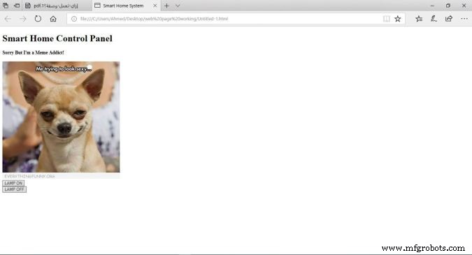
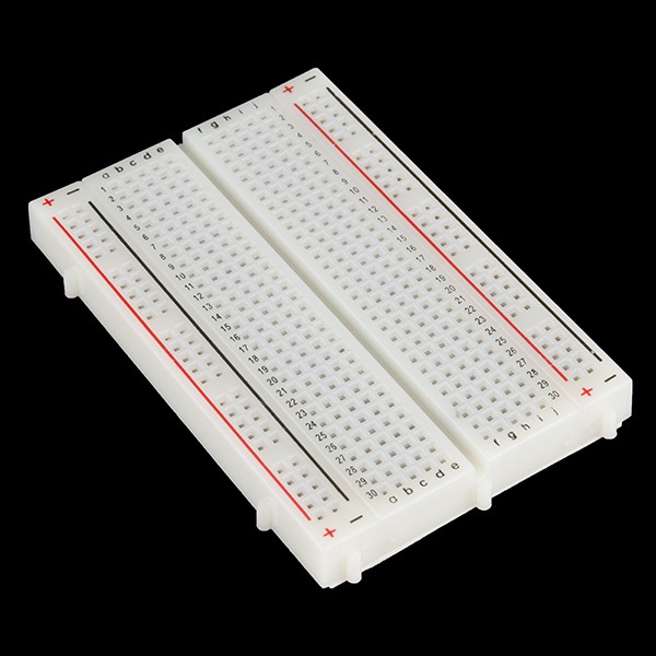
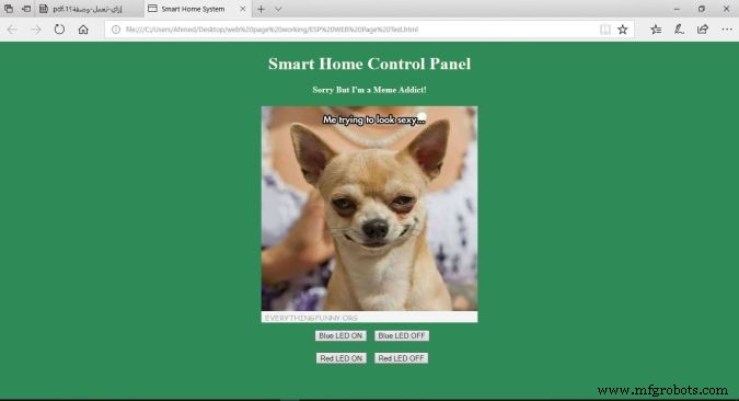
제어판은 매우 단순합니다. 각각 크기가 다른 2개의 헤더, 이미지 1개, LED를 켜기 위한 버튼과 끄기를 위한 버튼 2개가 포함되어 있습니다.
코드
스마트 홈 시스템
스마트 홈 제어판
죄송하지만 나는 밈 중독자입니다!
코드 설명
<울>
: 선언은 이 문서가 HMTL5 문서임을 정의합니다.
: HTML 페이지의 루트 요소입니다.
: 요소는 페이지에 대한 메타 정보를 포함합니다.
<제목>: 요소는 문서의 제목을 지정합니다. 이 제목은 웹페이지 브라우저 탭에 나타납니다.
: 요소는 보이는 웹페이지 콘텐츠를 포함합니다.
:
요소는 큰 요소를 정의합니다.
:
요소는 더 작은 헤더를 정의합니다. 헤더 값이 감소하면 글꼴이 감소합니다.
: 요소는 웹 페이지에 이미지를 추가합니다. 표시하려는 이미지는 동일한 프로젝트 폴더에 있어야 합니다.
: 커서를 새 줄로 이동합니다.
<버튼>: 요소는 페이지 콘텐츠에 버튼을 추가합니다.
각 버튼은 웹 페이지에 매우 중요한 두 가지 속성 id가 있습니다. 및 클래스 속성. Jquery 코드 설명에서 이 두 값을 버튼에 할당한 이유에 대해 이야기하겠습니다.
웹 페이지 스타일링
다음 설명을 쉽게 이해하려면 이 멋진 글을 읽는 것이 좋습니다. CSS 소개.
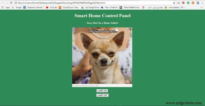
이제 웹 페이지가 더 멋지게 보입니다(너무 xD가 아님). 멋진 녹색 배경색을 지정하고 페이지 콘텐츠를 가운데 정렬하고 헤더 글꼴 색상과 글꼴 모음을 변경하여 웹 페이지를 더 생생하게 만듭니다. 우리는 CSS를 사용하여 이 모든 스타일링 작업을 수행했습니다.
웹 페이지를 더 보기 좋게 만들기 위해 몇 줄의 코드를 추가했습니다. style="background-color:seagreen; color:seashell; text-align:center;"를 추가했습니다. 본문 내부 태그 모든 웹페이지 콘텐츠를페이지 중앙에 만들려면 배경색을 바다색으로 설정 또한 글꼴 색상을 조개색으로 설정 .
또한 style="margin:10px;"을 추가했습니다. 두 개의 버튼 태그 내부 각 버튼의 4면 주위에 10픽셀의 여백을 설정합니다.
웹 서버에 요청 보내기
다음 설명을 쉽게 이해하려면 이 멋진 글을 읽는 것이 좋습니다. Jquery 소개.
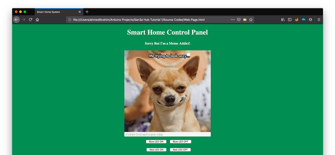
이제 웹 페이지 구조를 만들고 스타일을 지정한 후 웹 페이지에서 이전에 추가한 두 개의 버튼에 몇 가지 기능을 추가해야 합니다. 사용자가 "램프 켜기" 버튼을 클릭할 때 브라우저가 서버(ESP8266-01)에 일부 고유 데이터가 포함된 요청을 보낼 때 이 고유 데이터가 Arduino에 램프를 켜라고 지시합니다. 사용자가 클릭할 때 두 번째 버튼 "LAMP OFF"와 동일한 방식으로 브라우저는 서버(ESP8266-01)에 일부 고유 데이터가 포함된 요청을 보냅니다. 이 고유 데이터는 Arduino에게 램프를 끄도록 지시합니다. 코드를 살펴보겠습니다.
스마트 홈 시스템
스마트 홈 제어판
미안하지만 저는 밈 중독입니다!
<버튼 스타일="margin:10px;" id="110" class="button"> LAMP OFF
이 흥미로운 부분에서 모든 마법이 일어납니다.
Smart Home Control Panel
Sorry But I'm a Meme Addict!
How It Works
Just like the last trial, You upload the Arduino code to the board (if not uploaded yet) and open the serial monitor and make sure that your ESP module is connected successfully to your access point and got an IP and MAC address.
Then open your fancy web page and start controlling your stuff 😉
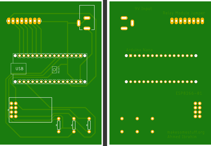
Make it more professional!
What about transferring our breadboard circuit to a professional printed circuit board (PCB) to make our project more rigid and solid, I designed the project circuit using Autodesk Eagle software. all the PCB files are open-source you can access it from this link:https://www.pcbway.com/project/shareproject/IoT_Using_Arduino_and_ESP8266_01.html
Because we love open source 😉
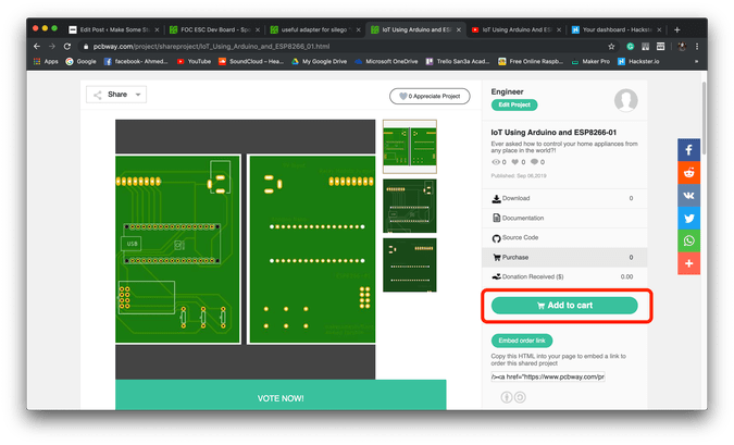
You can order your own PCB From PCBWay company these guys have a very good reputation in this field and they ship to more than 170 countries around the world with reasonable prices. all you have to do is to open the project PCB files link and press “Add to cart”. That’s it!
문제 해결
if your ESP Module is successfully connected to your access point but there is no action happens when you click the web page buttons
<울>
make sure that you are sending the request from your web browser from port 80(HTTP). example:
$.get("http://192.168.1.4:80/"
<울>
make sure that your PC or Laptop and the ESP module is connected to the same Access point.
In Jquery code, make sure that you wrote the right ESP module IP address.
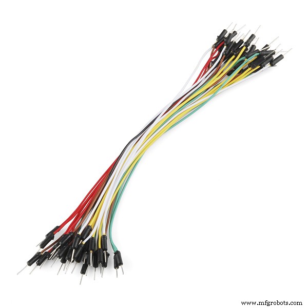
Make sure that you are connecting the load at Arduino digital pins 11 and 12.
Don’t forget to save the Web page code file after any change or modification, and reload the web page in the web browser after any code modification to take effect.
Final
We are done! in today’s tutorial, we learned how to build a simple web page using HTML, CSS, and jquery. Also, we learned how to control an AC load wirelessly from a web-based control panel, and how to use the awesome ESP8266-01 Wifi module with the Arduino board.
you wanna see more Tutorials and open source projects you can also visit my blog www.makesomestuff.org
Lastly, if you have any questions drop it in the comments section below, I will be more than happy to hear from you 😉
<섹션 클래스="섹션 컨테이너 섹션 축소 가능" id="코드">
코드
<울>
Web Page
Final Arduino Code
Web PageHTML
Smart Home System
Smart Home Control Panel
Sorry But I'm a Meme Addict!
Final Arduino CodeArduino
#include //including the SoftwareSerial library will allow you to use the pin no. 2,3 as Rx, Tx.SoftwareSerial esp8266(2,3); //set the Rx ==> Pin 2; TX ==> Pin3.#define serialCommunicationSpeed 9600 // <=========define a constant named "serialCommunicationSpeed" with a value 9600. it referes to the Software and hardware serial communication speed(baud rate).#define DEBUG true //make a constant named "DEBUG" and it's value true. we will use it later.int redLED =12; //assign a variable named "redLED" with an integer value 12, it refers to the pin which the red LED is connected on.int blueLED =11; //assign a variable named "blueLED" with an integer value 11, it refers to the pin which the blue LED is connected on.void setup(){ pinMode(redLED,OUTPUT); //set the pin number 12 as an output pin. pinMode(blueLED,OUTPUT); //set the pin number 11 as an output pin. digitalWrite(redLED,LOW); //turn the red LED off at the beginning of the program. digitalWrite(blueLED,HIGH); //turn the blue LED on at the beginning of the program. Serial.begin(serialCommunicationSpeed); //begin the Hardware serial communication (0, 1) at speed 9600. esp8266.begin(serialCommunicationSpeed); //begin the software serial communication (2, 3) at speed 9600. InitWifiModule(); //call this user-defined function "InitWifiModule()" to initialize a communication between the ESP8266 and your access point (Home Router or even your mobile hotspot). digitalWrite(blueLED,LOW); //after finishing the initialization successfully, turn off the blue LED (just an indicator).}void loop() //our main program, some fun are about to start){ if(esp8266.available()) //if there's any data received and stored in the serial receive buffer, go and excute the if-condition body. If not, dont excute the if-condition body at all. { if(esp8266.find("+IPD,")) //search for the "+IPD," string in the incoming data. if it exists the ".find()" returns true and if not it returns false. { delay(1000); //wait 1 second to fill up the buffer with the data. int connectionId =esp8266.read()-48; //Subtract 48 because the read() function returns the ASCII decimal value. And 0 (the first decimal number) starts at 48. We use it to convert from ASCI decimal value to a character value. esp8266.find("pin="); //Advance the cursor to the "pin=" part in the request header to read the incoming bytes after the "pin=" part which is the pinNumer and it's state. int pinNumber =(esp8266.read()-48)*10; //read the first Byte from the Arduino input buffer(i.e. if the pin 12 then the 1st number is 1) then multiply this number by 10. So, the final value of the "pinNumber" variable will be 10. pinNumber =pinNumber + (esp8266.read()-48); //read the second Byte from the Arduino input buffer(i.e. if the pin number is 12 then the 2nd number is 2) then add this number to the first number. So, the final value of the "pinNumber" variable will be 12. int statusLed =(esp8266.read()-48); //read the third byte from the Arduino input buffer. then save it inside the "statusLed" variable. At any case, it will be 1 or 0. digitalWrite(pinNumber, statusLed); //then turn the LED at "pinNumber" on or off depending on the "statusLed" variable value. Serial.println(connectionId); //print the "connectionId" value on the serial monitor for debugging purposes. Serial.print(pinNumber); //print the "pinNumber" value on the serial monitor for debugging purposes. Serial.print(" "); //print some spaces on the serial monitor to make it more readable. Serial.println(statusLed); //print the "statusLed" value on the serial monitor for debugging purposes. String closeCommand ="AT+CIPCLOSE="; //close the TCP/IP connection. closeCommand+=connectionId; //append the "connectionId" value to the string. closeCommand+="\r\n"; //append the "\r\n" to the string. it simulates the keyboard enter press. sendData(closeCommand,1000,DEBUG); //then send this command to the ESP8266 module to excute it. } }}/******************************************************************************************************************************************************************************************* Name:sendData* Description:this Function regulates how the AT Commands will ge sent to the ESP8266.* * Params:command - the AT Command to send * - timeout - the time to wait for a response * - debug - print to Serial window?(true =yes, false =no)* * Returns:The response from the esp8266 (if there is a reponse)*/String sendData(String command, const int timeout, boolean debug){ String response =""; //initialize a String variable named "response". we will use it later. esp8266.print(command); //send the AT command to the esp8266 (from ARDUINO to ESP8266). long int time =millis(); //get the operating time at this specific moment and save it inside the "time" variable. while( (time+timeout)> millis()) //excute only whitin 1 second. { while(esp8266.available()) //is there any response came from the ESP8266 and saved in the Arduino input buffer? { char c =esp8266.read(); //if yes, read the next character from the input buffer and save it in the "response" String variable. response+=c; //append the next character to the response variabl. at the end we will get a string(array of characters) contains the response. } } if(debug) //if the "debug" variable value is TRUE, print the response on the Serial monitor. { Serial.print(response); } return response; //return the String response.}/******************************************************************************************************************************************************************************************* Name:InitWifiModule* Description:this Function gives the commands that we need to send to the sendData() function to send it.* * Params:Nothing.* * Returns:Nothing (void).*/void InitWifiModule(){ sendData("AT+RST\r\n", 2000, DEBUG); //reset the ESP8266 module. //delay(1000); sendData("AT+CWJAP=\"Decoder\",\"1241997GoGo\"\r\n", 2000, DEBUG); //connect to the WiFi network. delay (3000); sendData("AT+CWMODE=1\r\n", 1500, DEBUG); //set the ESP8266 WiFi mode to station mode. delay (1500); sendData("AT+CIFSR\r\n", 1500, DEBUG); //Show IP Address, and the MAC Address. delay (1500); sendData("AT+CIPMUX=1\r\n", 1500, DEBUG); //Multiple conections. delay (1500); sendData("AT+CIPSERVER=1,80\r\n", 1500, DEBUG); //start the communication at port 80, port 80 used to communicate with the web servers through the http requests.}


 <울>
<울>