

VHDL

산업 제조
이 튜토리얼에서는 사용자가 정의한 주파수로 LED를 구동하는 VHDL 및 Verilog 코드를 작성하는 방법을 배웁니다. 귀하의 업무 흐름에 가장 적합한 언어를 선택하세요.
HDL을 작성할 때 설계가 의도한 대로 작동하는지 확인해야 합니다. 실수는 피할 수 없으므로 시뮬레이션은 필수입니다. 이 튜토리얼은 두 가지 중요한 단계로 나누어져 있습니다:
시뮬레이션을 건너뛰면 하드웨어 디버깅에 비용이 많이 들 수 있습니다. 시뮬레이션을 필수 체크포인트로 삼으세요.
50% 듀티 사이클로 100Hz, 50Hz, 10Hz 또는 1Hz에서 LED를 깜박이는 HDL을 작성하세요. 두 개의 스위치가 원하는 주파수를 선택하고 추가 LED_EN LED를 활성화하려면 스위치가 높아야 합니다. FPGA는 25MHz 발진기에서 실행됩니다.
주파수 선택기의 진리표:
| 활성화 | 스위치1 | 스위치2 | LED 구동 주파수 |
|---|---|---|---|
| 0 | - | - | 비활성화 |
| 1 | 0 | 0 | 100Hz |
| 1 | 0 | 1 | 50Hz |
| 1 | 1 | 0 | 10Hz |
| 1 | 1 | 1 | 1Hz |
신호 요약:
| 신호 이름 | 방향 | 설명 |
|---|---|---|
| i_clock | 입력 | 25MHz 클럭 |
| i_enable | 입력 | 스위치 활성화(logic0 =LED 꺼짐) |
| i_switch_1 | 입력 | 주파수 선택 스위치1 |
| i_switch_2 | 입력 | 주파수 선택 스위치2 |
| o_led_drive | 출력 | LED 구동 신호 |
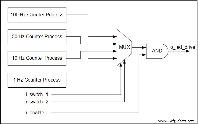
4개의 동시 카운터 프로세스는 25MHz 클록을 모니터링하고 각 대상 주파수에 대한 토글을 생성합니다. 특정 주파수를 선택하지 않은 경우에도 해당 카운터는 계속 실행됩니다. 이는 하드웨어 동시성의 핵심 원칙입니다.
스위치는 선택한 토글을 LED 출력으로 라우팅하는 멀티플렉서를 형성합니다. 멀티플렉서는 순전히 조합 논리이므로 클록 없이 작동합니다.
다음은 아키텍처를 보여주는 블록 다이어그램입니다:
library ieee;
use ieee.std_logic_1164.all;
use ieee.numeric_std.all;
entity tutorial_led_blink is
 port (
 i_clock : in std_logic;
 i_enable : in std_logic;
 i_switch_1 : in std_logic;
 i_switch_2 : in std_logic;
 o_led_drive : out std_logic
 );
end tutorial_led_blink;
architecture rtl of tutorial_led_blink is
 -- Constants to create the frequencies needed:
 -- Formula is: (25 MHz / 100 Hz * 50% duty cycle)
 -- So for 100 Hz: 25,000,000 / 100 * 0.5 = 125,000
 constant c_CNT_100HZ : natural := 125000;
 constant c_CNT_50HZ : natural := 250000;
 constant c_CNT_10HZ : natural := 1250000;
 constant c_CNT_1HZ : natural := 12500000;
 -- These signals will be the counters:
 signal r_CNT_100HZ : natural range 0 to c_CNT_100HZ;
 signal r_CNT_50HZ : natural range 0 to c_CNT_50HZ;
 signal r_CNT_10HZ : natural range 0 to c_CNT_10HZ;
 signal r_CNT_1HZ : natural range 0 to c_CNT_1HZ;

 -- These signals will toggle at the frequencies needed:
 signal r_TOGGLE_100HZ : std_logic := '0';
 signal r_TOGGLE_50HZ : std_logic := '0';
 signal r_TOGGLE_10HZ : std_logic := '0';
 signal r_TOGGLE_1HZ : std_logic := '0';
 -- One bit select wire.
 signal w_LED_SELECT : std_logic;

begin
 -- All processes toggle a specific signal at a different frequency.
 -- They all run continuously even if the switches are
 -- not selecting their particular output.

 p_100_HZ : process (i_clock) is
 begin
 if rising_edge(i_clock) then
 if r_CNT_100HZ = c_CNT_100HZ-1 then -- -1, since counter starts at 0
 r_TOGGLE_100HZ <= not r_TOGGLE_100HZ;
 r_CNT_100HZ <= 0;
 else
 r_CNT_100HZ <= r_CNT_100HZ + 1;
 end if;
 end if;
 end process p_100_HZ;
 p_50_HZ : process (i_clock) is
 begin
 if rising_edge(i_clock) then
 if r_CNT_50HZ = c_CNT_50HZ-1 then -- -1, since counter starts at 0
 r_TOGGLE_50HZ <= not r_TOGGLE_50HZ;
 r_CNT_50HZ <= 0;
 else
 r_CNT_50HZ <= r_CNT_50HZ + 1;
 end if;
 end if;
 end process p_50_HZ;

 p_10_HZ : process (i_clock) is
 begin
 if rising_edge(i_clock) then
 if r_CNT_10HZ = c_CNT_10HZ-1 then -- -1, since counter starts at 0
 r_TOGGLE_10HZ <= not r_TOGGLE_10HZ;
 r_CNT_10HZ <= 0;
 else
 r_CNT_10HZ <= r_CNT_10HZ + 1;
 end if;
 end if;
 end process p_10_HZ;

 p_1_HZ : process (i_clock) is
 begin
 if rising_edge(i_clock) then
 if r_CNT_1HZ = c_CNT_1HZ-1 then -- -1, since counter starts at 0
 r_TOGGLE_1HZ <= not r_TOGGLE_1HZ;
 r_CNT_1HZ <= 0;
 else
 r_CNT_1HZ <= r_CNT_1HZ + 1;
 end if;
 end if;
 end process p_1_HZ;

 -- Create a multiplexor based on switch inputs
 w_LED_SELECT <= r_TOGGLE_100HZ when (i_switch_1 = '0' and i_switch_2 = '0') else
 r_TOGGLE_50HZ when (i_switch_1 = '0' and i_switch_2 = '1') else
 r_TOGGLE_10HZ when (i_switch_1 = '1' and i_switch_2 = '0') else
 r_TOGGLE_1HZ;

 -- Only allow o_led_drive to drive when i_enable is high (and gate).
 o_led_drive <= w_LED_SELECT and i_enable;
end rtl;
module tutorial_led_blink
(
 i_clock,
 i_enable,
 i_switch_1,
 i_switch_2,
 o_led_drive
 );
 input i_clock;
 input i_enable;
 input i_switch_1;
 input i_switch_2;
 output o_led_drive;

 // Constants (parameters) to create the frequencies needed:
 // Input clock is 25 kHz, chosen arbitrarily.
 // Formula is: (25 kHz / 100 Hz * 50% duty cycle)
 // So for 100 Hz: 25,000 / 100 * 0.5 = 125
 parameter c_CNT_100HZ = 125;
 parameter c_CNT_50HZ = 250;
 parameter c_CNT_10HZ = 1250;
 parameter c_CNT_1HZ = 12500;
 // These signals will be the counters:
 reg [31:0] r_CNT_100HZ = 0;
 reg [31:0] r_CNT_50HZ = 0;
 reg [31:0] r_CNT_10HZ = 0;
 reg [31:0] r_CNT_1HZ = 0;

 // These signals will toggle at the frequencies needed:
 reg r_TOGGLE_100HZ = 1'b0;
 reg r_TOGGLE_50HZ = 1'b0;
 reg r_TOGGLE_10HZ = 1'b0;
 reg r_TOGGLE_1HZ = 1'b0;

 // One bit select
 reg r_LED_SELECT;
 wire w_LED_SELECT;


begin
 // All always blocks toggle a specific signal at a different frequency.
 // They all run continuously even if the switches are
 // not selecting their particular output.
 always @ (posedge i_clock)
 begin
 if (r_CNT_100HZ == c_CNT_100HZ-1) // -1, since counter starts at 0
 begin
 r_TOGGLE_100HZ <= !r_TOGGLE_100HZ;
 r_CNT_100HZ <= 0;
 end
 else
 r_CNT_100HZ <= r_CNT_100HZ + 1;
 end

 always @ (posedge i_clock)
 begin
 if (r_CNT_50HZ == c_CNT_50HZ-1) // -1, since counter starts at 0
 begin
 r_TOGGLE_50HZ <= !r_TOGGLE_50HZ;
 r_CNT_50HZ <= 0;
 end
 else
 r_CNT_50HZ <= r_CNT_50HZ + 1;
 end
 always @ (posedge i_clock)
 begin
 if (r_CNT_10HZ == c_CNT_10HZ-1) // -1, since counter starts at 0
 begin
 r_TOGGLE_10HZ <= !r_TOGGLE_10HZ;
 r_CNT_10HZ <= 0;
 end
 else
 r_CNT_10HZ <= r_CNT_10HZ + 1;
 end

 always @ (posedge i_clock)
 begin
 if (r_CNT_1HZ == c_CNT_1HZ-1) // -1, since counter starts at 0
 begin
 r_TOGGLE_1HZ <= !r_TOGGLE_1HZ;
 r_CNT_1HZ <= 0;
 end
 else
 r_CNT_1HZ <= r_CNT_1HZ + 1;
 end
 // Create a multiplexer based on switch inputs
 always @ (*)
 begin
 case () // Concatenation Operator
 2'b11 : r_LED_SELECT <= r_TOGGLE_1HZ;
 2'b10 : r_LED_SELECT <= r_TOGGLE_10HZ;
 2'b01 : r_LED_SELECT <= r_TOGGLE_50HZ;
 2'b00 : r_LED_SELECT <= r_TOGGLE_100HZ;
 endcase
 end
 assign o_led_drive = r_LED_SELECT & i_enable;
 // Alternative way to design multiplexer (same as above):
 // More compact, but harder to read, especially to those new to Verilog
 // assign w_LED_SELECT = i_switch_1 ? (i_switch_2 ? r_TOGGLE_1HZ : r_TOGGLE_10HZ) :
 //(i_switch_2 ? r_TOGGLE_50HZ : r_TOGGLE_100HZ);
 // assign o_led_drive = w_LED_SELECT & i_enable;


end

endmodule
다음 단계:VHDL 또는 Verilog에서 이 설계를 시뮬레이션하여 배포 전에 올바른 동작을 확인합니다.
VHDL
2025년 글로벌 시장 분석:종이 변환 기계 선두업체 및 신흥 업체 글로벌 종이 변환 기계 시장의 급성장하는 범위 전 세계 산업이 지속 가능성을 향해 빠르게 움직이고 있는 가운데, 글로벌 종이 변환 기계 시장의 구성 요소는 엄청난 변화를 겪었습니다. 위생용품, 지속 가능한 포장, 효율적인 종이 기반 솔루션에 대한 수요가 계속 증가함에 따라 시장은 예상했던 것 이상으로 확장되었습니다. 펄프 및 제지 기계 시장 규모는 소비자 동향, 환경 규칙 및 기술 변화로 인해 계속해서 크게 증가하고 있습니다. 하지만 질문이 생깁니다. 이렇
자바 LinkedBlockingQueue 이 자습서에서는 예제를 통해 LinkedBLockingQueue 클래스와 해당 메서드에 대해 알아봅니다. LinkedBlockingQueue Java Collections 클래스 프레임워크는 연결 목록을 사용하여 차단 대기열 구현을 제공합니다. Java BlockingQueue 인터페이스를 구현합니다. LinkedBlockingQueue 생성 연결된 차단 대기열을 생성하려면 java.util.concurrent.LinkedBlockingQueue를 가져와야 합니다. 패키지. J