

제조공정

산업 제조
 |
| × | 1 |
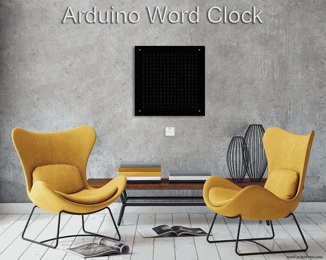
이 빌드에 대한 자세한 내용은 여기 내 사이트에서 찾을 수 있습니다. Word Clock
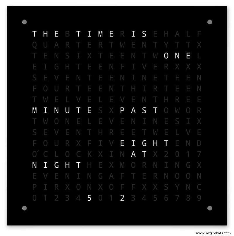
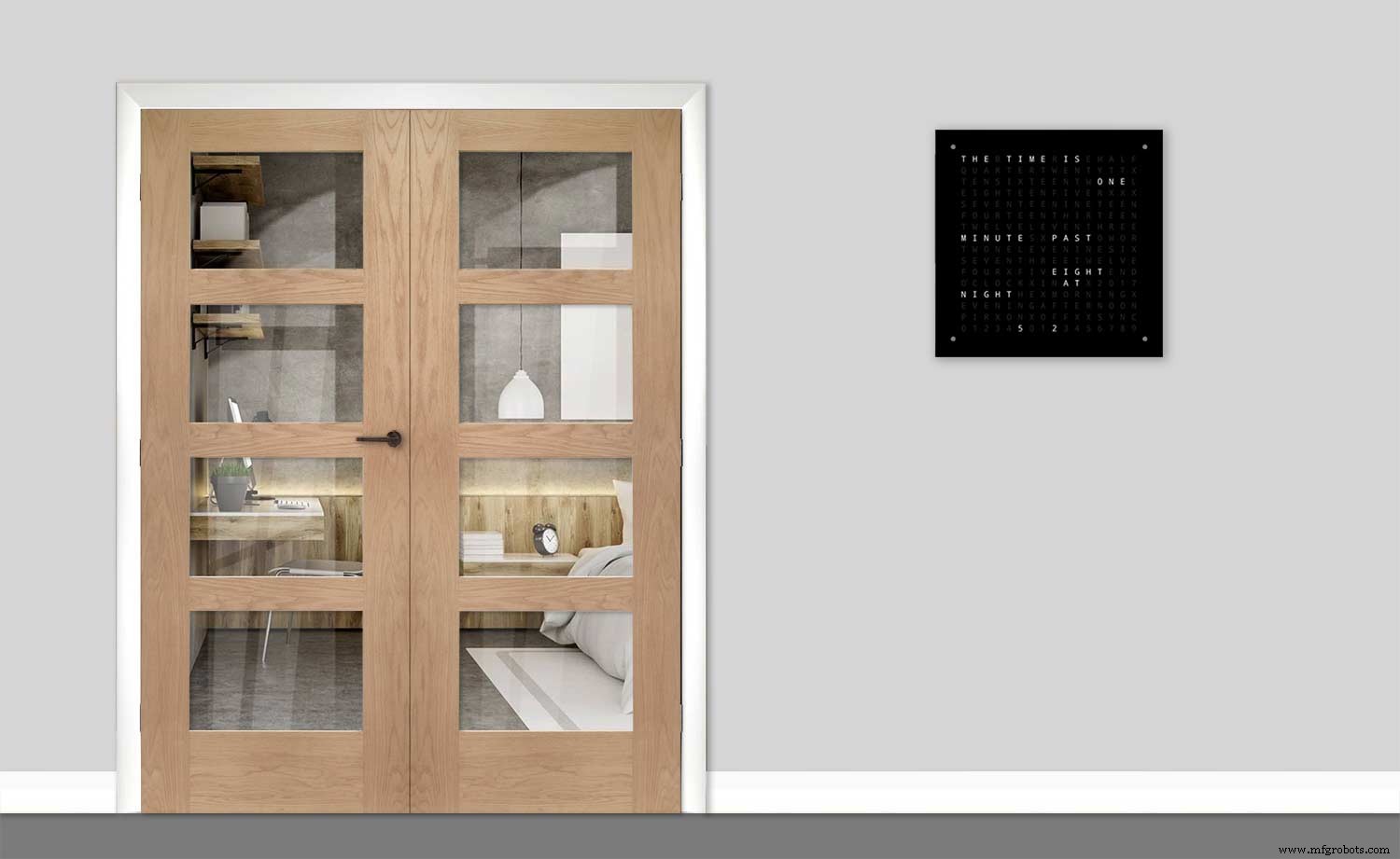
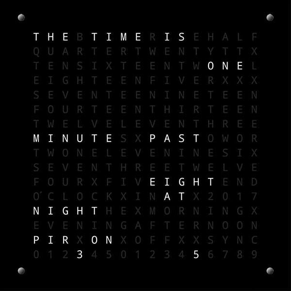
단어 단위의 미세한 시간 분해능과 초 단위의 선형 표시 기능이 있는 Arduino 단어 시계.
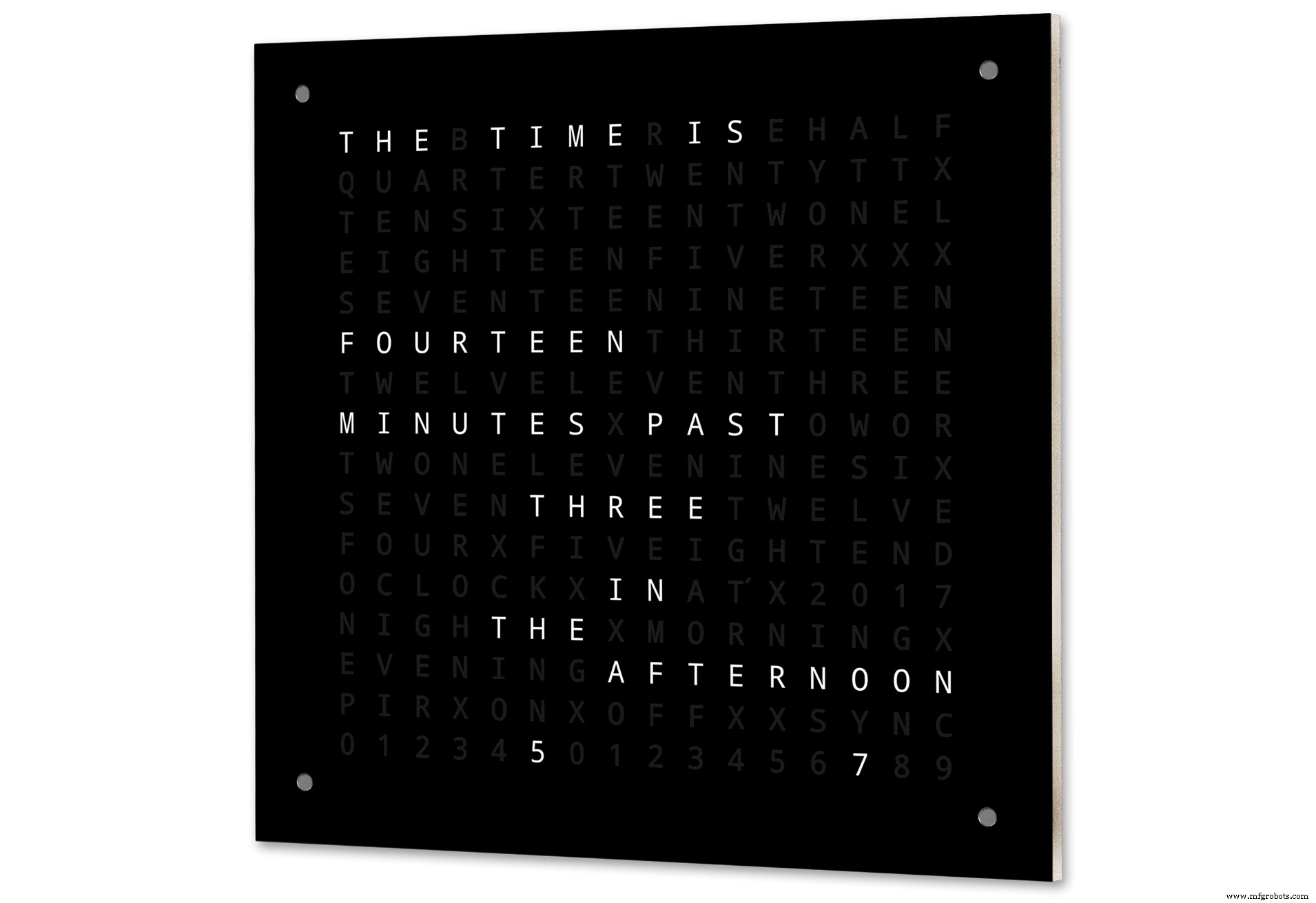
디지털 시계, 아날로그 시계, 온도 및 습도 모드와 Game of Life, Simon 및 Tetris의 세 가지 게임도 있습니다.
클럭은 독립 실행형이거나 필요한 경우 마스터 클럭의 슬레이브로 실행할 수 있습니다.
마스터 클럭이 없으면 워드 클럭에 내장된 온도 보상형 실시간 클럭에 의해 시간이 제어됩니다.
방에 아무도 없을 때 시계가 자동으로 꺼지도록 PIR 또는 도플러 레이더 제어 옵션이 있습니다.
시계의 크기는 500mm x 500mm(19.68" x19.68")이고 무게는 5.5Kg이며 벽에 장착하도록 설계되었습니다. 각 모서리에는 시계를 설정하고 제어할 수 있는 터치 패드가 있습니다.
1단계:단어 시계 정보
워드 클록 정보
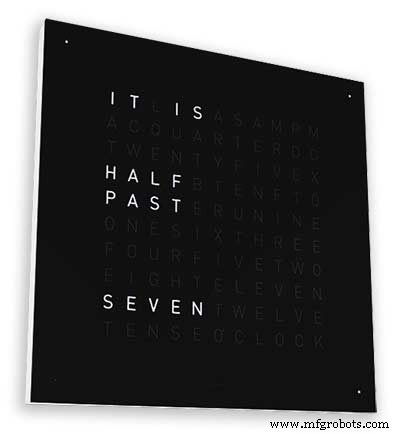
단어 시계는 단어 또는 숫자 및 문자의 행렬을 사용하여 시간을 알려주며 수년 동안 사용되어 왔습니다. 클럭 빌드의 복잡성에 영향을 미치는 몇 가지 다른 디자인 유형이 있습니다.
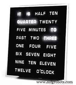
O'CLOCK, 5 PAST, 10 PAST 등의 가장 간단한 단어 블록을 사용하여 5분 분해능으로 시간을 알려줍니다. 이 시계는 20개 정도의 개별 LED 블록만 사용하므로 구성이 가장 간단합니다. 이 시계의 가장 큰 단점은 이 설정된 형식으로만 시간을 표시할 수 있다는 것입니다.
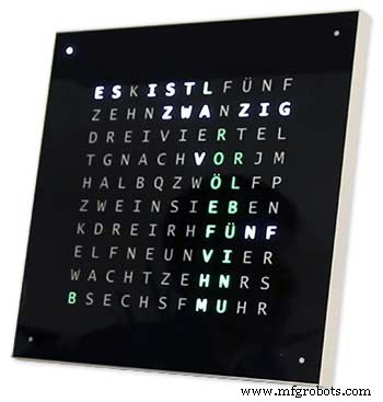
중간 수준의 시계에는 11x10 LED 매트릭스와 시계 외부에 4개의 추가 LED가 있습니다. Raspberry Pi 제어 시계 Photo 2에는 다색 LED도 있고 110개의 개별 LED가 있으므로 숫자와 기본 이미지를 표시할 수 있습니다. 이 시계는 여전히 단어로 5분 해상도를 사용하지만 종종 해상도를 약간 높이기 위해 "방금 5초" 또는 거의 10분을 추가합니다. 종종 프레임 모서리 주위에 있는 4개의 LED는 시간 간격을 채우는 데 4분이 경과했음을 나타냅니다. 5분 단위의 해상도를 제공합니다. 이 시계는 만들기가 상당히 복잡하며 종종 LED 스트립을 사용하여 보다 쉽게 만들 수 있습니다.
이 시계 유형의 상업용 버전을 사용할 수 있습니다. 450mm 벽걸이 버전은 £1000 정도이며 다양한 색상과 재질로 전면 패널을 교체할 수 있으며 더 작은 데스크탑과 시계도 사용할 수 있습니다.
Wouter Devinck의 256 매트릭스 워드 클록
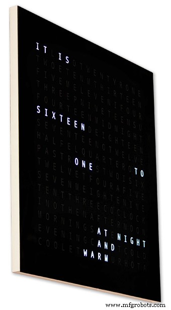
가장 복잡한 수준의 단어 시계는 16x16 LED 매트릭스를 사용하여 전체 256개의 LED를 제어하여 제어합니다. 이 시계는 아침, 저녁, 밤 등은 물론이고 1분 단위로 표시된 시간 분해능을 가지고 있습니다. 그들은 종종 단어로 대략적인 온도를 알려줍니다. 따뜻함, 매우 따뜻함, 추위 매우 추움 등
256개의 LED와 함께 사용할 수 있는 다양한 디스플레이 모드가 있습니다. 이러한 시계는 매트릭스 디스플레이의 연결 수로 인해 구축하기가 매우 복잡합니다. 표면 실장 구성 요소가 있는 PCB에 LED 매트릭스를 구축하면 시계 본체가 매우 슬림해지고 디스플레이 구성이 더 간단해 지지만 500mm x 500mm 이상에서는 PCB가 비싸지기 시작합니다.
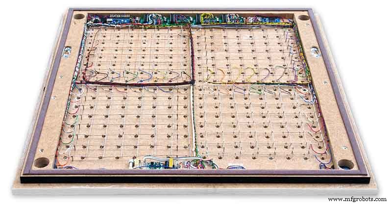
내 시계에서와 같이 LED 매트릭스를 손으로 구축하려면 공간이 필요하며 500mm x 500mm는 LED와 디스플레이 모듈을 상호 연결하는 데 필요한 대형 배선 직기를 수용할 수 있기 때문에 좋은 출발점입니다. 손으로 만든 LED 매트릭스를 사용하여 벽을 채우는 매우 큰 시계를 만들 수 있습니다.
2단계:변경 사항
변경 사항
이 시계는 Wouter Devinck Clock 하드웨어와 "Catalan" Pijuana 시계 소프트웨어가 혼합되어 있습니다. 나는 어떤 PCB도 사용하지 않고 단지 기성품 모듈과 전원을 위한 3개의 작은 Vero 보드 회로를 사용했습니다.
주요 변경 사항은 아래에 자세히 설명되어 있습니다.
이 시계 버전에는 맞춤형 PCB가 사용되지 않으며 사전 제작된 모듈에서 쉽게 구할 수 있습니다.
시계 본체는 단일 18mm 시트가 아닌 14mm MDF 2장으로 제작되었습니다.
뒷면 시트는 앞면 시트보다 윗면을 제외한 모든 면이 10mm 작아서 시계 두께가 14mm에 불과한 것처럼 보입니다.
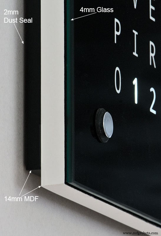
Wouter Devinck 시계는 2mm 유리를 포함하여 깊이가 단 20mm인 반면, 제 시계는 후면에 4mm 유리와 2mm 더스트 씰을 포함하여 실제로 34mm입니다. 후면 14mm 패널의 셋백과 대부분의 각도에서 유리 패널의 1.5mm 셋백으로 인해 시계는 14mm 깊이만 보입니다. 이 추가 깊이 덕분에 4개의 대형 PCB 대신 손으로 만든 LED 매트릭스와 배선 직기를 사용할 수 있었습니다. 이는 또한 MAX7219 보드에서 표면 실장 IC 없이 사전 제작된 유지 관리 친화적 모듈을 사용할 수 있음을 의미합니다.
메인 디스플레이는 PCB 없이 디스플레이 LED에 직접 제작되어 어떤 크기의 디스플레이도 가능합니다. 메인 보드에 장착된 Azoteq IQS127D 대신 TTP223 터치 센서 모듈을 사용합니다.
MAX7219 I/C용 디스플레이 드라이버 보드는 수정된 LED 매트릭스 보드를 사용합니다. 이 보드에는 모든 구성 요소가 포함되어 있습니다.
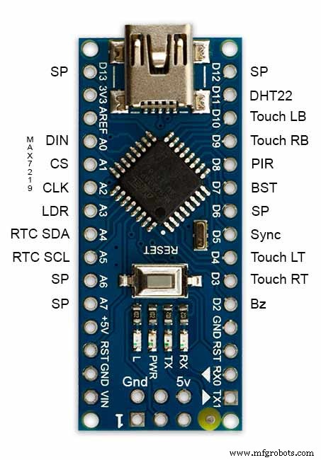
아두이노 나노는 크기가 작기 때문에 시계를 구동하는 데 사용됩니다.
PIR 센서 모듈은 방에 아무도 없을 때 디스플레이를 종료하는 데 사용됩니다(디스플레이를 항상 켜진 상태로 유지하기 위해 비활성화할 수 있음).
자동 디스플레이 밝기를 보정하기 위해 작은 일자 드라이버로 시계 하단에서 접근할 수 있는 트리머 저항이 회로에 추가되었습니다.
30초에 1분마다 내 마스터 시계 시스템과 동기화합니다. 동기화 펄스를 사용할 수 없는 경우 클럭은 RTC를 사용하여 자유 실행됩니다. 동기화 펄스가 메인 디스플레이에 표시됩니다.
소프트웨어는 주로 단어 시계의 "카탈루냐" Pijuana 버전을 기반으로 하므로 디스플레이를 위해 영어로 번역되었습니다. 현재 소프트웨어 버전 번호, 내 이름 및 빌드 연도를 표시하도록 "카탈루냐" Pijuana" 버전에서 수정된 크레딧 표시.
단어가 표시된 온도는 시계 디스플레이에서 제거되고 선형 초 표시는 워드, 디지털 및 아날로그 시계의 맨 아래 행에 추가되었습니다.
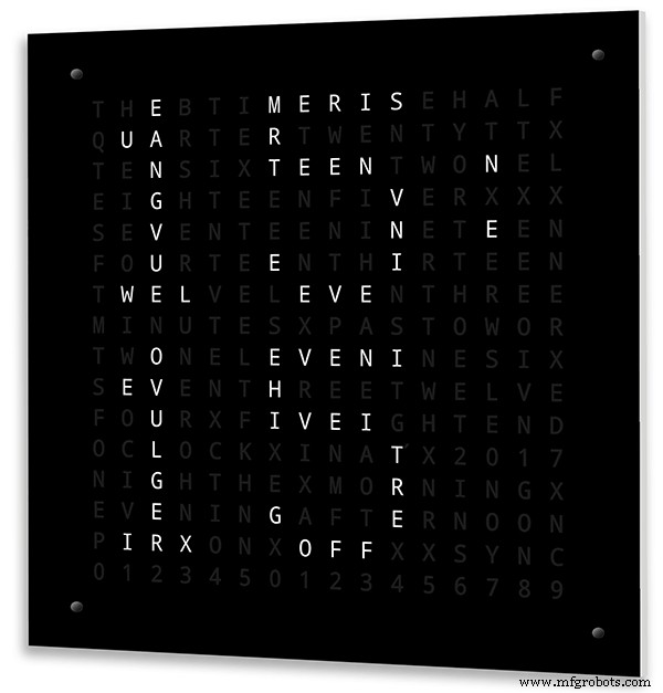
PIR이 켜지거나 꺼지면 워드 클럭 디스플레이에 "PIR ON" 또는 "PIR OFF"가 몇 초 동안 표시됩니다.
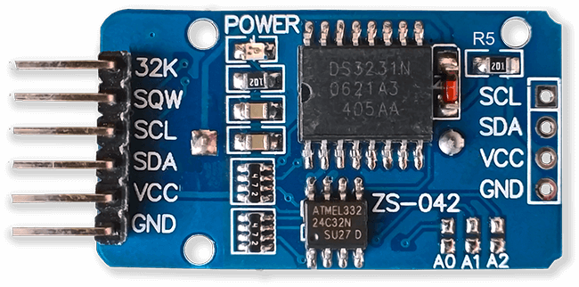
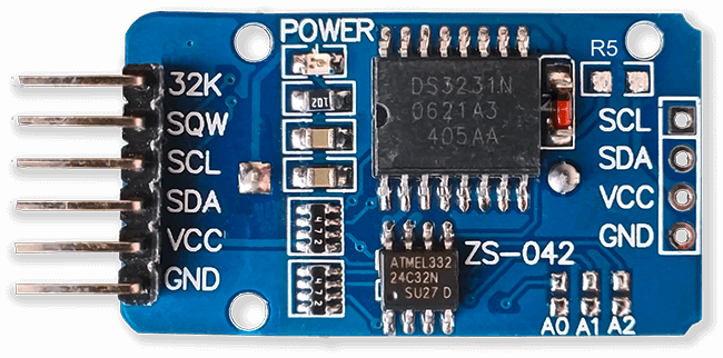
이 시계는 Wouter Devinck 시계 및 "카탈루냐" Pijuana 시계에 따라 DS3231 AT24C32 I2C 정밀 실시간 시계 모듈을 사용합니다. 모듈과 함께 제공되는 리튬 이온 충전식 배터리를 사용하고 싶지 않습니다. 비충전식 배터리를 사용하고 모듈을 그에 맞게 수정했습니다.
폴리싱 처리된 가장자리가 있는 4mm 플로트 유리가 2mm 유리를 대체합니다. 유리는 접착제가 아닌 시카고 패스너를 사용하여 메인 MDF 보드에 고정됩니다. 시계를 제어하는 터치 패드 역할도 하며 필요한 경우 유리를 제거할 수 있습니다.
두 개의 더스트 씰이 시계에 내장되어 있습니다. 하나는 후면 패널에, 다른 하나는 탈착식 유리 디스플레이 패널 뒤에 있습니다. 시계 설정 모드에서 BOT 오른쪽 버튼을 누르면 이제 초가 0으로 재설정됩니다.
영어 표현에 다음과 같은 변경을 가하여 내가 말하는 대로의 표현을 만들었습니다. 개인이 시간을 말하는 방식은 거주지/학교 등에 따라 지역마다 다를 것입니다. 가장 적합하게 들리는 방식은 없습니다.
단어 시계에서 온도를 나타내는 단어를 제거했습니다. 이들은 동기화 상태, PIR ON/OFF 및 선형 표시(초)로 대체되었습니다.
과거 1분 및 시 1분에 "MINUTES"를 "MINUTE"로 변경했습니다.
과거 "QUARTER" 앞에 "A"를 추가하고 시간에 "QUARTER"를 추가했습니다.
그의 메모에 따라 Wouter Devinck 시계에서 누락된 "ELEVEN"을 추가했습니다.
정오에 시간을 오후 12시로 변경했습니다.
자정에 시간이 밤 12시로 변경되었습니다. 자정이 지나면 시계는 항상 아침에 알려줍니다.
"O'CLOCK"은 이제 구두점이 없고 OCLOCK만 표시됩니다.
3단계:케이스 디자인
내 시계는 표면 실장 부품이 있는 맞춤형 디스플레이 매트릭스 PCB를 사용하지 않기 때문에 시계 케이스는 Wouter의 디자인보다 약간 더 깊어야 합니다.
내 케이스는 깊이가 34mm이고 후면 더스트 씰 2mm, 후면 MDF 보드 14mm, 전면 디스플레이 보드 14mm 및 4mm 플로트 유리를 포함합니다.
Wouter의 오른쪽 케이스는 깊이가 21mm, 단일 MDF 패널이 18mm, 플로트 유리가 2mm입니다.
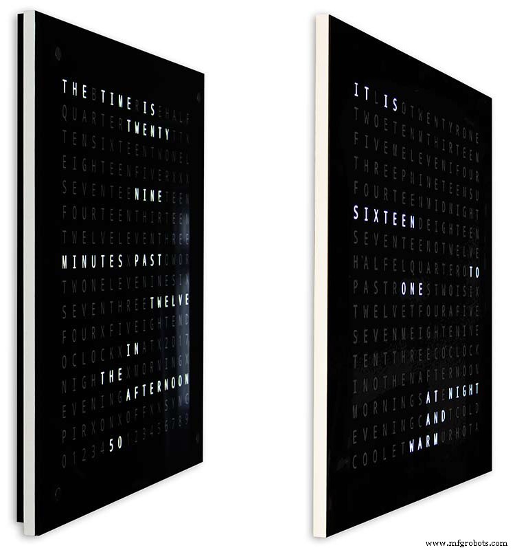
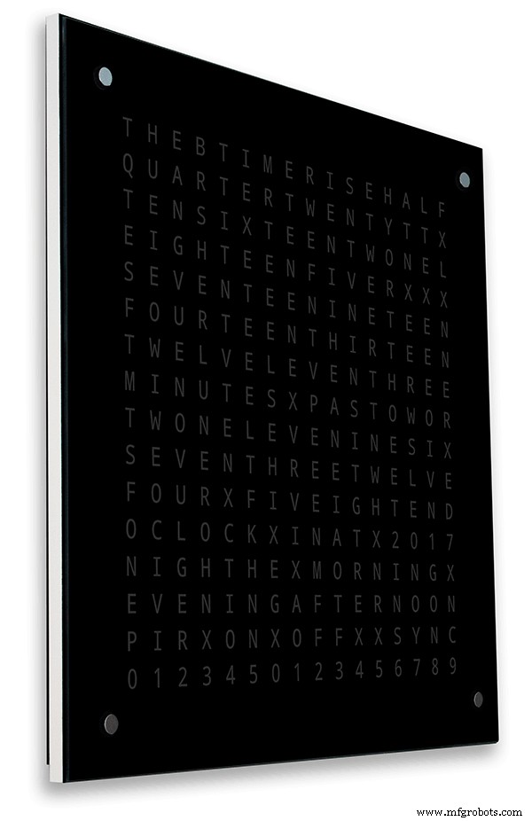
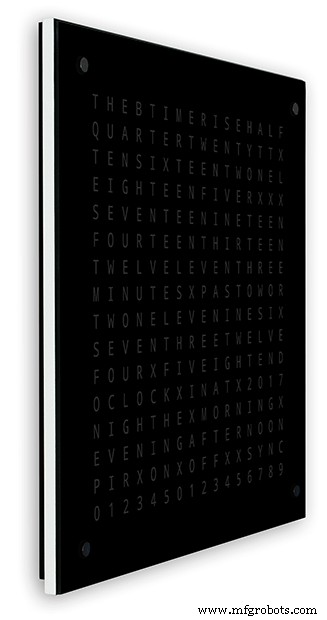
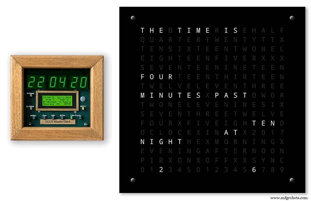
벽에 걸었을 때 시계가 눈에 덜 커보이도록 하기 위해 몇 가지 간단한 디자인 기능을 통합했습니다. 위의 그림은 왼쪽에 내 시계가 있고 오른쪽에 Wouter의 시계가 있습니다. 극단적 인 측면 각도보기에서 내 케이스가 더 부피가 커 보이는 것을 분명히 볼 수 있습니다.
이것은 후면 보드가 흰색이 아닌 검정색으로 되어 있어 슬림한 흰색 14mm 가장자리에 시선이 집중되도록 합니다. 후면 보드는 바닥과 양쪽이 10mm 더 짧고 이러한 착시 현상을 나타냅니다.
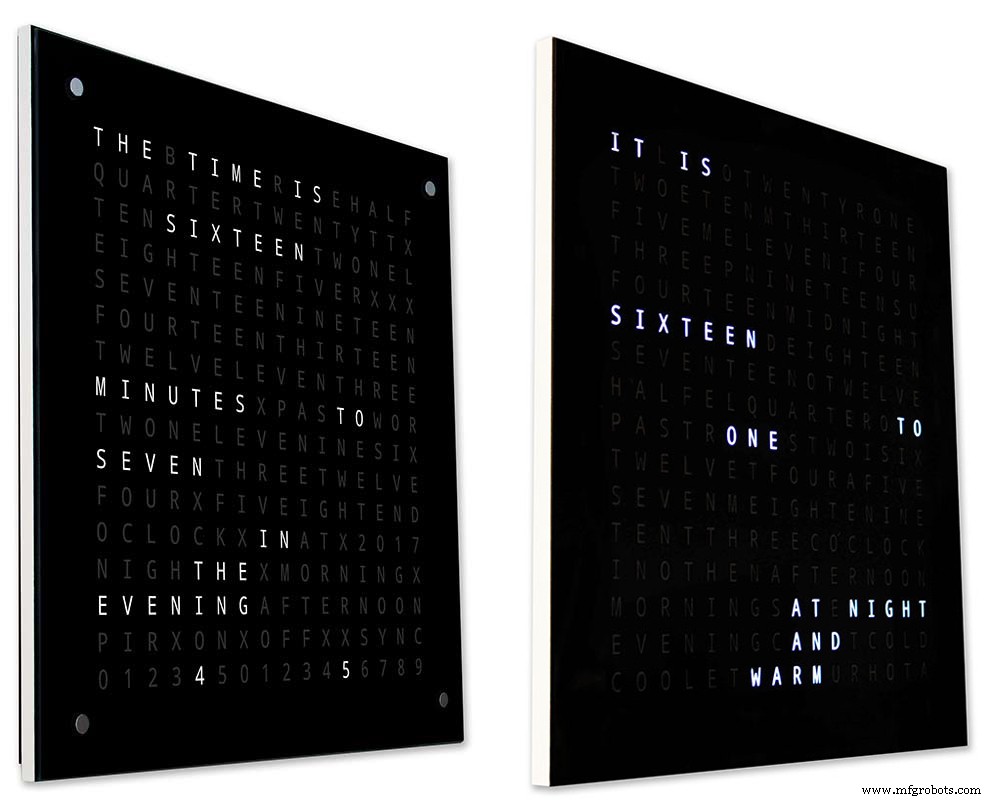
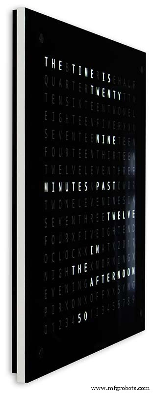
위 - 다시 왼쪽에 내 시계가 있고 오른쪽에 Wouter의 시계가 있습니다. 시계 앞쪽으로 더 가면 내 시계의 더 짧은 후면 보드가 시야에서 사라집니다. 슬림한 14mm 전면 보드만 보일 때까지입니다. 4mm 유리도 전면 보드보다 1-2mm 짧게 잘라서 보이지 않게 숨깁니다. . 내 부피가 큰 34mm 시계 케이스는 이제 Wouter의 케이스만큼 슬림해 보입니다.
4단계:제어
컨트롤

시계의 TTP223 터치 제어 모듈은 디스플레이의 왼쪽 상단, 오른쪽 상단, 왼쪽 하단 및 오른쪽 하단 모서리에 있습니다.
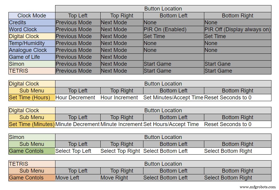
버튼은 시계가 어떤 모드에 있는지에 따라 다른 기능을 합니다. 위의 표를 참조하십시오.
5단계:자동 여름 겨울 설정
사용하지 않습니다.
6단계:디스플레이 모드 시계 및 환경
위의 애니메이션 1은 4가지 시계 및 환경 모드를 보여줍니다.
모드는 단어시계, 디지털시계, 온습도, 아날로그시계 순입니다.
위의 애니메이션 2. 소프트웨어 버전 번호, 제조업체 이름 및 시계 이름을 스크롤하는 시작 모드도 있습니다.
7단계:디스플레이 모드 게임
세 가지 고전 게임이 시계에 코딩되어 있습니다. 나는 카탈로니아 시계의 코드를 그대로 두었습니다.

Conway의 Game of Life 위에 있는 애니메이션 1. Game of Life의 우주는 정사각형 셀의 무한한 2차원 직교 그리드이며, 각 셀은 두 가지 가능한 상태(살아있거나 죽었거나, "채워진" 또는 "채워지지 않은" 상태) 중 하나에 있습니다.
모든 셀은 수평, 수직 또는 대각선으로 인접한 셀인 8개의 이웃과 상호 작용합니다. 시간의 각 단계에서 다음과 같은 전환이 발생합니다. 살아있는 이웃이 2개 미만인 살아있는 세포는 마치 인구 부족으로 인한 것처럼 죽습니다. 2~3개의 살아있는 이웃이 있는 살아있는 세포는 다음 세대까지 살아갑니다. 3개 이상의 살아있는 이웃이 있는 살아있는 세포는 마치 인구 과잉으로 인해 죽습니다. 정확히 3개의 살아있는 이웃이 있는 죽은 세포는 마치 번식에 의한 것처럼 살아있는 세포가 됩니다.
초기 패턴은 시스템의 시드를 구성합니다. 첫 번째 세대는 위의 규칙을 종자의 모든 세포에 동시에 적용하여 생성되고 동시에 발생하며, 이것이 발생하는 불연속적인 순간을 때때로 틱이라고 합니다(즉, 각 세대는 이전의 순수 함수입니다. 하나). 규칙은 다음 세대를 만들기 위해 계속 반복적으로 적용됩니다.
사이먼 위의 애니메이션 2
사이먼 메모리 게임 - 컴퓨터에서 생성된 시퀀스를 복사하고 시도합니다. 시퀀스를 입력할 때 마지막 항목을 두 번 탭하여 턴을 종료합니다.
실패하면 점수가 화면에 표시됩니다.
TetrisTetris 위의 애니메이션 3은 1984년 6월에 출시된 소련 타일 짝 맞추기 퍼즐 비디오 게임입니다. 이 게임은 타일을 올바르게 제어하기 위한 버튼 작업이 아직 필요합니다.
8단계:프로토타입 제작
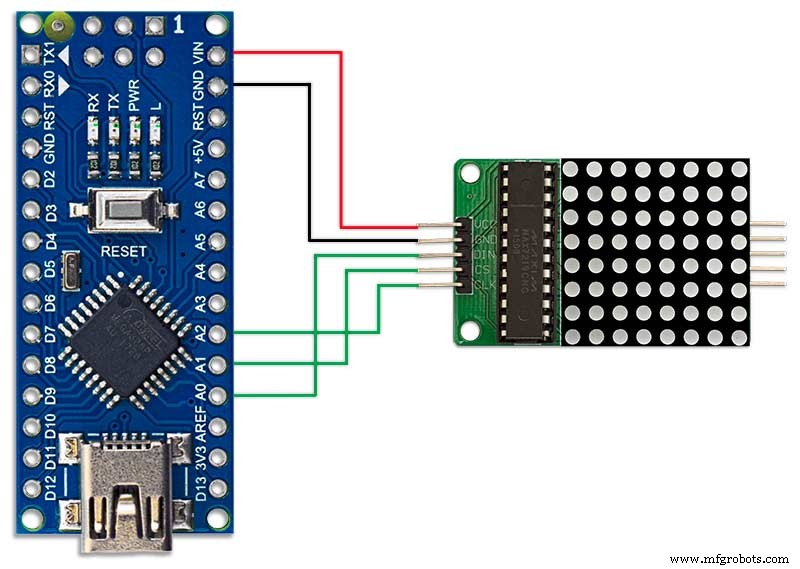
클록은 MAX7219 디스플레이 보드의 원래 DOT 매트릭스 LED를 사용하여 프로토타입을 만들고 테스트할 수 있습니다.
이 임시 수정은 MAX7219 모듈과 함께 제공된 DOT 매트릭스 디스플레이에서 코드를 테스트하려는 경우에만 필요합니다.
즉, 전체 크기 버전으로 커밋하기 전에 소프트웨어/단어 레이아웃 수정을 미니어처로 시도할 수 있습니다. 소프트웨어 연결과 일치하도록 DOT Matrix LED에 대한 배선을 수정해야 합니다.
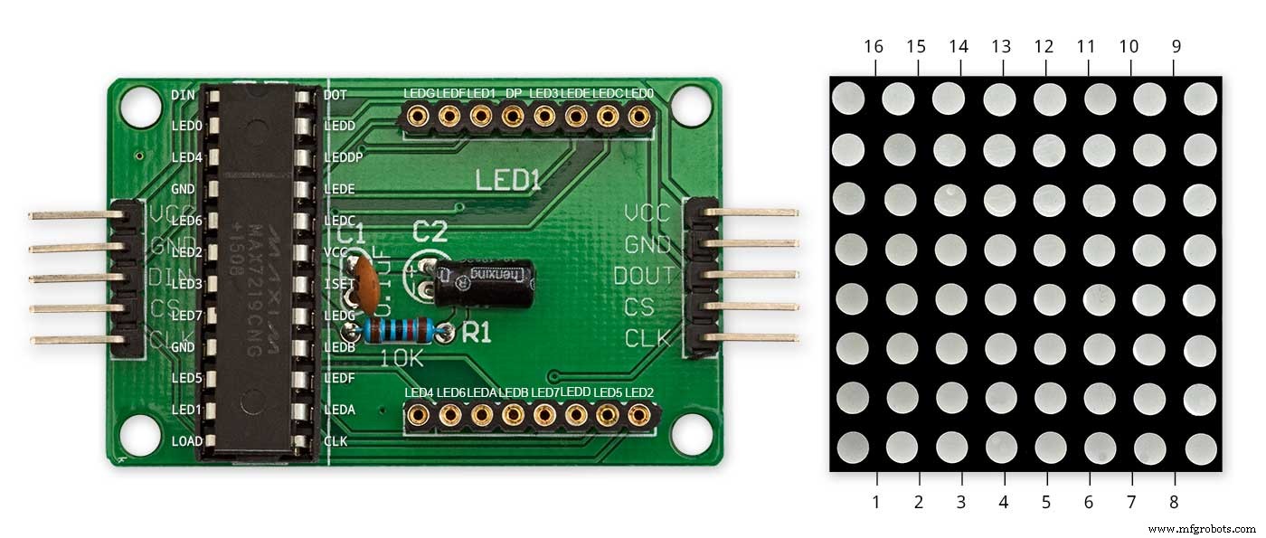
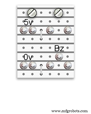
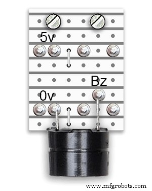
위의 그림은 모듈이 수정되기 전에 어떻게 배선되었는지 보여줍니다. 수정은 매우 간단합니다. 먼저 다음 LED Matrix 핀을 90° 구부려 위쪽 핀은 위로, 아래쪽 핀은 아래로 향하게 합니다.
핀 16, 15, 3, 4, 10 및 11.
디스플레이 PCB의 소켓에 LED Matrix를 삽입하면 위의 핀이 이제 연결되지 않습니다. 디스플레이 PCB 소켓 뒷면에서 튀어나온 LED Matrix 핀까지 다음 링크 와이어를 납땜합니다.
도트 매트릭스 핀 16에 대한 LEDA
LEDB에서 도트 매트릭스 핀 15
도트 매트릭스 핀 3에 대한 LEDG
도트 매트릭스 핀 4에 대한 LEDF
도트 매트릭스 핀 10에 대한 LEDE
도트 매트릭스 핀 11에 대한 LEDC
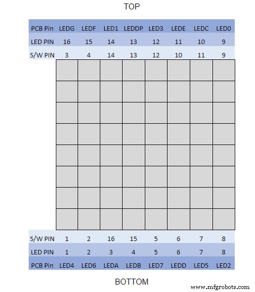
나는 멀티 미터를 사용하고 디스플레이 모듈을 윙윙 거리는 소리를 내었습니다. 표는 소프트웨어 핀 번호가 디스플레이 보드의 LED 핀 번호와 다른 부분을 보여줍니다.
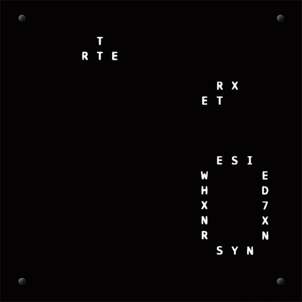
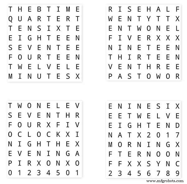
단어 레이아웃을 테스트하려면 일반 흰색 종이에 62mm x 62mm 크기의 단어 디스플레이의 축소판을 인쇄하십시오.
소프트웨어 레이아웃과 일치하도록 LED 디스플레이 보드의 방향을 확인하십시오.
누군가가 내 시계에 Wouter Devinck PCB 디자인을 사용할 경우를 대비하여 디스플레이 회전을 원래 Wouter Devinck 시계로 유지했습니다.
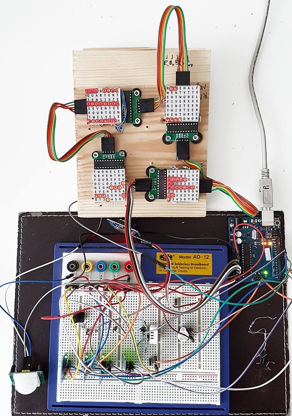
온도/습도 센서 아래에 있는 작은 푸시 버튼은 30초 동기화를 테스트하는 데 사용됩니다. 터치 버튼 모듈은 옆으로 장착된 브레드보드의 왼쪽 하단에 있습니다. 대부분의 배선이 디스플레이 매트릭스에 있으므로 이 프로토타입에는 배선이 많지 않습니다. 마지막 시계에서 이 배선은 개별 LED에 손으로 수행됩니다.
최종 시계를 만들기 전에 이 보드에서 다양한 단어/시계 디자인을 시도했습니다.
9단계:수정된 모듈 테스트
배선 모드 후에 MAX2719 모듈을 테스트할 수 있도록 워드 클록 스케치를 수정했습니다.
이 모든 프로그램은 매트릭스의 왼쪽 상단에서 오른쪽 하단으로 차례로 각 LED를 켭니다.
5개의 와이어를 NANO 및 MAX2719 모듈에 연결하고 USB 포트에서 NANO에 전원을 공급하기만 하면 됩니다. 스케치를 로드하고 실행하십시오.
각 모듈을 차례로 연결하여 배선을 확인하기만 하면 됩니다.
동봉된 zip 파일에서 테스트 스케치를 다운로드하세요.
MAX7219_LED_Test.zip
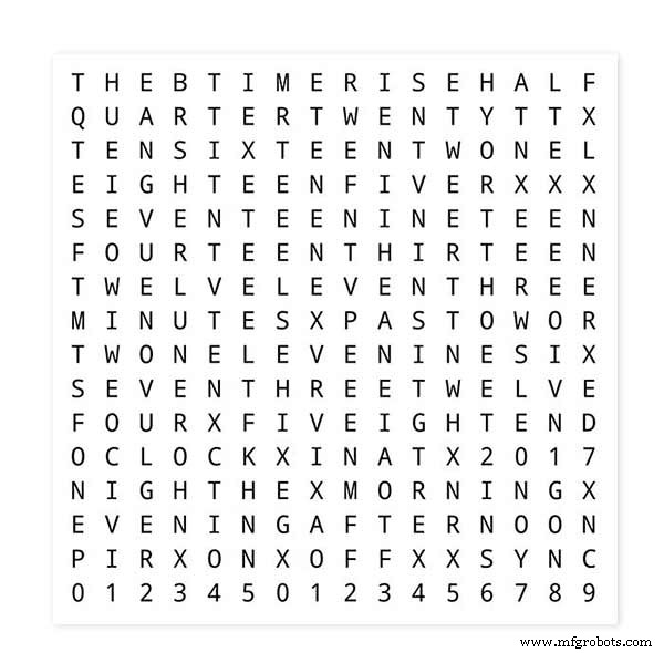
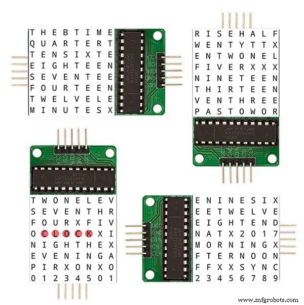
10단계:단어 매핑 시간
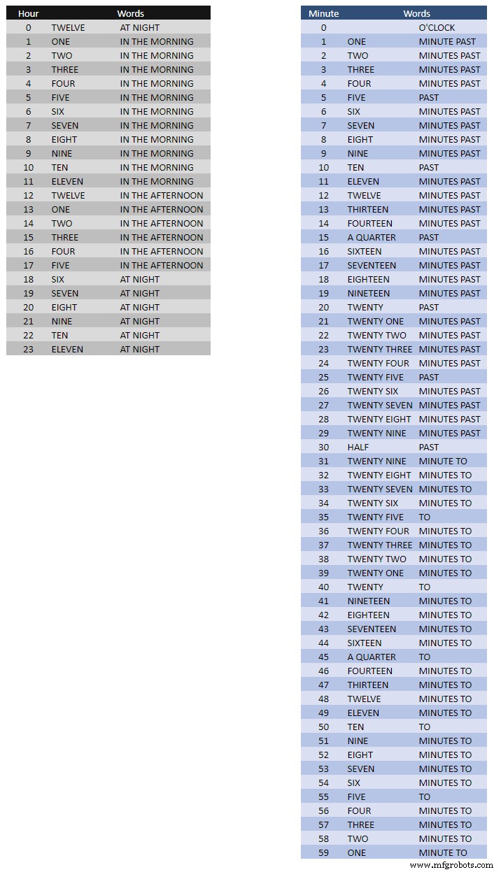
위의 표는 단어 매핑에 대한 시간을 보여줍니다.
이것에 대한 어렵고 빠른 규칙은 없습니다. 당신이 시간을 말하는 것처럼 단어를 설정하십시오.
내 시계에서 나는 Wouter의 시계에 있는 단어와 비교하여 다음을 변경했습니다.
'MINUTES'가 1분 경과 후 1분에 'MINUTE'로 변경되었습니다. 과거 "QUARTER" 앞에 "A"를 추가하고 시간에 "QUARTER"를 추가했습니다.
정오에 시간을 오후 12시로 변경했습니다.
자정에 시간이 밤 12시로 변경되었습니다.
자정이 지나면 시계는 항상 IN 아침을 가리킵니다.
이러한 변경 사항은 시계 소프트웨어에서 구현하기가 매우 쉽습니다.
단어%2Bto%2BTime%2BTranslations.xlsx
11단계:전원
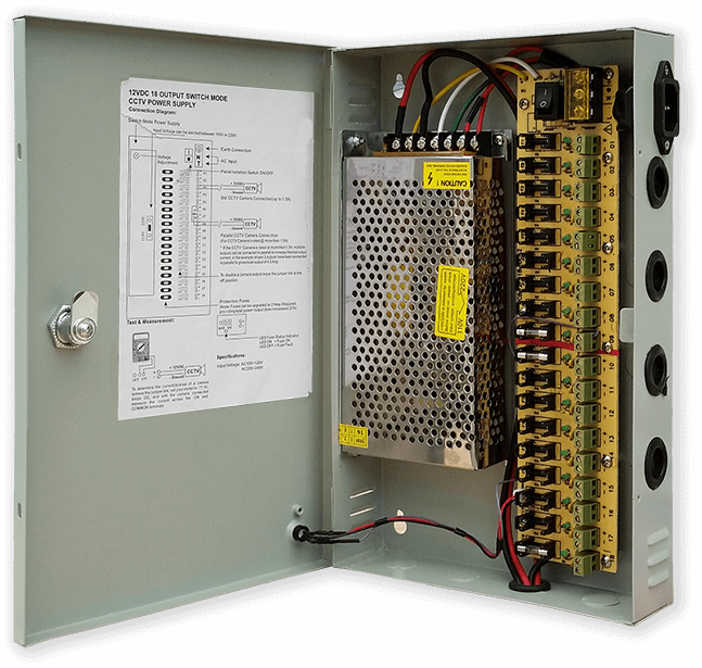
나는 집 전체에서 다양한 유형의 회로를 구동하기 위해 일반적인 12볼트 전원 공급 장치를 사용합니다. 그런 다음 이 12볼트 공급은 5볼트 모듈과 함께 각 회로에서 국부적으로 강압되어 제어 보드 및 다양한 모듈에 전원을 공급합니다.
내 공통 전원 공급 장치에는 각각 2A 퓨즈가 있는 18개의 개별 퓨즈 12v 회로가 있습니다. 이 중 9개는 백업된 배터리입니다. 시계판에도 자체 퓨즈가 있습니다.
이 하나의 회로만 실행하는 경우 조정된 5볼트 공급 장치는 회로 사용에 필요한 전류를 공급할 수 있는 한 작동합니다.
MP1584 미니어처 전원 공급 장치를 사용하는 Vero의 전원 보드를 설계했습니다. 이것은 내 공통 전원 공급 장치의 12v 출력을 클록용 5v로 변환합니다.
Vero 보드로 구성된 두 개의 추가 전원 보드가 있습니다.
부저를 들고 있는 것 외에도 시계의 전원 배선을 위한 추가 전원 분배 지점을 추가합니다.
전원 요구사항
나는 시계에서 전류 소모를 측정했으며 낮은 밝기에서 30mA 및 전체 밝기 250mA를 사용합니다. 물론 이것은 얼마나 많은 LED가 켜져 있는지에 따라 다릅니다. 밝고 화창한 날 직렬 출력에 표시된 밝기 수준은 10입니다. 이는 LED 최대 전력의 약 2/3입니다. PIR을 켜면 전체 전력 소비를 크게 줄일 수 있습니다. 시계에 움직임이 감지되지 않으면 디스플레이가 비어 있습니다.
나는 시계에 전원을 공급하기 위해 최소 500mA 전원을 사용할 것입니다. 전원은 공급하는 LED 유형에 따라 크게 달라집니다.
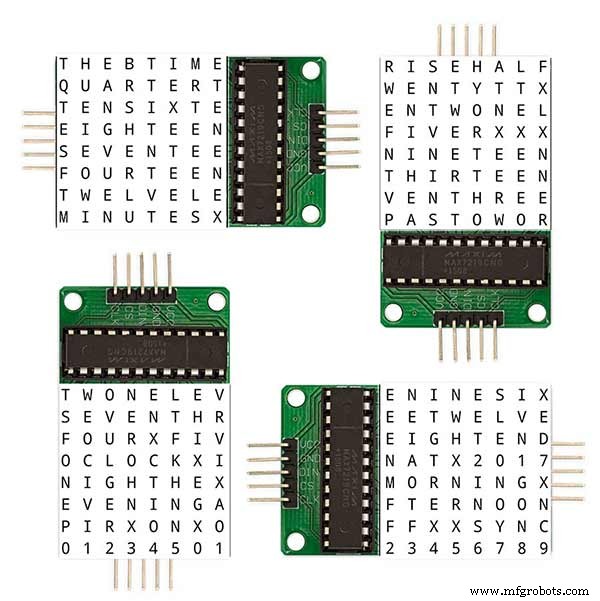
12단계:모듈 상호 연결
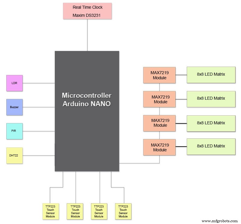
위의 그림은 모듈이 어떻게 연결되어 있는지 보여줍니다. 대부분의 모듈은 Arduino Nano에 직접 연결됩니다.
MAX7219 보드는 모듈 01을 통해서만 NANO에 연결됩니다. 다른 모듈은 함께 데이지 체인 방식으로 연결됩니다.
각 8x8 LED 매트릭스는 MAX7219 모듈에 연결됩니다.
대부분의 배선은 MAX7219 모듈과 LED 매트릭스 간의 연결입니다.
NANO와 첫 번째 MAX7219 모듈 및 MAX7219 모듈과 모듈 사이의 거리를 최대한 짧게 유지하십시오. 또한 대부분의 전력이 회로의 이 부분에서 소모되므로 데이지 체인 방식으로 연결된 MAX7219의 양쪽 끝에 전원을 공급해야 합니다.
13단계:건설 건설 순서
모든 프로토타이핑 및 소프트웨어 변경이 먼저 완료된 것으로 가정한 빌드 순서입니다.
비닐 전사지를 인쇄하십시오.
유리 컷을 받으세요.
MDF 시트를 앞뒤로 잘라냅니다.
LED용 전면 시트에 구멍을 뚫습니다.
MDF 시트를 페인트하십시오.
유리에 센서용 구멍을 뚫습니다.
유리 뒷면에 비닐 전사지를 붙입니다.
MDF 전면 보드의 센서 구멍을 자릅니다.
전면 보드에서 센서 모듈 리베이트를 줄입니다.
MDF 백보드를 자르고 센서 접근을 위한 4개의 접근 구멍을 만드십시오.
MDF 보드에 멜라민 가장자리 스트립을 추가하고 전면 보드에 흰색, 후면 보드에 검정색을 추가합니다.
후면 MDF 보드를 전면 MDF 보드에 나사로 고정합니다.
Vero 보드, 전원 보드 1개, 배전 보드 2개를 만드세요.
4 x MAX7219 보드를 수정하고 LED에 배선을 추가합니다.
지금은 MAX7219 끝에서 연결하십시오.
MDF 전면 보드 후면에 모든 모듈과 Vero 보드를 장착합니다.
전면 MDF 보드에 4개의 LED 매트릭스를 모두 구성하고 256개의 LED를 납땜합니다.
모든 Batt 및 Earth는 전원 공급 장치 Vero 보드 및 배전 보드에서 실행됩니다.
모든 전원을 모든 모듈에 연결합니다.
모든 배선을 Nano, MAX7219 모듈, RTC, 온도 센서, 터치 센서 및 부저에 연결합니다.
수정된 MAX7219 보드의 모든 배선 직기를 배선 테이블에 따라 LED 매트릭스에 연결합니다.
시계에서 원격으로 PIR 모듈을 연결하고 PIR 연결을 연결합니다.
30초 동기화를 마스터 시계에 연결합니다(필요한 경우).
동시에 터치 센서를 고정하는 시카고 볼트를 사용하여 Glass 전면 디스플레이 패널을 장착합니다.
테스트.
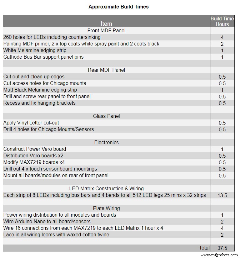
표 1은 이 시계의 대략적인 제작 시간을 보여주며 기술 수준과 손에 넣어야 하는 전문 도구/작업 공간에 따라 달라집니다.
해당 목록에 다른 40시간의 프로토타이핑 및 프로그래밍 시간을 쉽게 추가할 수 있습니다.
14단계:건설용 비닐 스티커
비닐 스티커
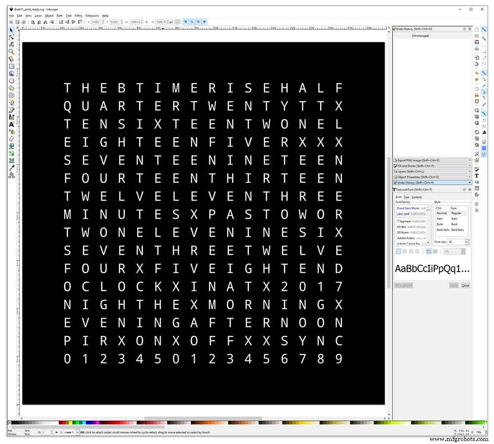
비닐 스티커는 Inkscape로 디자인되었습니다.
Inkscape는 Windows, Mac OS X 및 GNU/Linux에서 실행되는 전문적인 품질의 벡터 그래픽 소프트웨어입니다. 일러스트레이션, 아이콘, 로고, 다이어그램, 지도 및 웹 그래픽과 같은 다양한 그래픽을 만들기 위해 전 세계의 디자인 전문가와 애호가가 사용합니다.
Inkscape는 W3C 개방형 표준 SVG(Scalable Vector Graphics)를 기본 형식으로 사용하며 무료 및 오픈 소스 소프트웨어입니다.
Wouter Devinck의 GitHub 리포지토리에서 원본 Inkscape 디자인을 다운로드한 다음 내 디자인에 맞게 Inkscape에서 수정했습니다. 나는 최종 디자인을 인쇄하기 위해 보내기 전에 미니어처 프로토타입에서 다양한 버전을 시도했습니다.
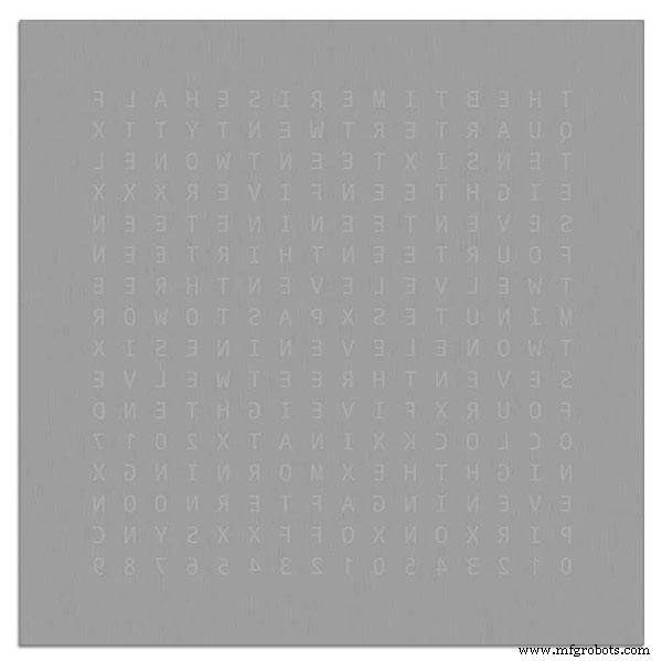
스티커 뒷면 인쇄도 잊지 마세요!
나는 검정 비닐, 리버스 컷, 레터링 제초제로 스티커를 제공하고 부가세 포함 £27에 응용 테이프를 제공한 Regal Signs &Graphics라는 회사를 사용했습니다.
그들은 나에게 꽤 현지인이지만 조금 더 지불하고 멋진 안전한 판지 튜브에 내 스티커를 배달했습니다.
디자인을 컴퓨터에 맞는 형식으로 가져오는 데 몇 가지 문제가 있었지만 결국에는 Illustrator에서 EPS 형식으로 보냈습니다. Regal Signs의 매우 도움이 되는 사람들이 그것을 올바른 크기로 축소했습니다. 내 Inkscape 파일을 다운로드할 수 있습니다. 여기 비닐 스티커.
비닐 스티커는 글자를 제거한 상태로 Regal Signs에서 가져왔기 때문에 많은 시간을 절약할 수 있었습니다. 스티커는 앞면(유리) 면에 플라스틱 테이프가 있고 뒷면에 응용 프로그램 용지가 함께 제공됩니다. 보통은 양면테이프를 떼어내고 스티커를 붙인 후 붙인 종이를 떼어냅니다. 나는 그것이 LED의 디퓨저 역할을하기 때문에 신청서를 그대로 두기로 결정했습니다. 저는 신청용지를 그대로 두고 붙이기 전에 스티커 주변의 여분의 종이를 잘라냈습니다.
스티커 적용은 비교적 쉬웠습니다. 직접 시도하기 전에 유리에 비닐 스티커 부착에 대한 YouTube 동영상을 몇 개 시청하십시오.
유리

시계는 4mm 플로트 유리를 사용하며 정확히 500mm x 500mm로 절단되었습니다. 가장자리가 노출되면서 가장자리도 광택 처리되었습니다. 이것은 모두 £ 20에 지역 유리공이 수행했습니다.
그런 다음 5mm 유리 드릴을 사용하여 유리 패널에 5mm 구멍을 뚫었습니다. 유리에 구멍을 뚫는 방법에 대한 YouTube 동영상을 확인하십시오.
나는 먼저 아세톤으로 유리를 닦고 먼지가 없는지 확인했습니다(매우 중요). 그런 다음 스티커에 지문이 묻지 않도록 플라스틱 장갑을 끼었습니다.
나는 유리에 매우 희석된 비누와 물 혼합물을 뿌린 다음 스티커에서 플라스틱 필름을 아주 천천히 벗겨내어 전면을 드러냈습니다.
스티커의 글자가 전사지에 연결된 상태를 유지하도록 필름을 아주 예각으로 천천히 다시 벗겨내는 것이 중요합니다. 스티커가 완전히 노출되면 젖은 유리 표면에 붙입니다.
물/비누 혼합물을 사용하면 스티커를 유리의 올바른 위치로 이동할 수 있습니다. 다음으로 신용카드를 사용하여 스티커 중앙에서 떼어내 기포를 제거합니다. 스티커를 밤새 건조시킨 다음 스티커 뒷면에서 유리에 있는 4개의 장착 구멍 위의 비닐을 잘라냅니다.
Brett11_print_ready.svg
15단계:메인 보드 구성 1부
메인 보드
시계의 메인보드는 14mm MDF 2장으로 구성되어 있습니다. 후면 시트는 상판을 제외한 모든 면이 상판보다 10mm 작습니다. 상단에는 흰색 가장자리가 있고 후면에는 검은색 가장자리가 있습니다. 벽에서 볼 때 시계는 14mm 깊이로 나타납니다.

시계의 메인보드는 14mm MDF 2장으로 구성되어 있습니다. 후면 시트는 상판을 제외한 모든 면이 상판보다 10mm 작습니다. 상단에는 흰색 가장자리가 있고 후면에는 검은색 가장자리가 있습니다. 벽에서 볼 때 시계는 14mm 깊이로 나타납니다.
원래 Wouter Devinck Clock 및 "Catalan" Pijuana 버전에서는 단일 18mm 두께의 MDF 시트가 후면과 함께 사용되어 PCB 및 구성 요소를 위한 공간을 확보합니다. MDF 2장을 사용하면 시간이 많이 걸리고 먼지가 많은 라우팅 대신 퍼즐을 사용하여 백보드를 간단히 잘라낼 수 있습니다. 상단 시트는 503mm x 503mm로 유리 주위에 1.5mm 겹침을 제공합니다. 이렇게 하면 유리가 노크로부터 약간의 보호를 받을 수 있습니다.

백보드는 퍼즐을 사용하여 잘라내고 14mm의 구성 요소 공간을 허용합니다.
부품을 포함한 가장 깊은 PCB는 10mm 깊이의 MAX 7219 모듈입니다. 완료되면 후면 보드가 전면 보드에 접착되거나 나사로 고정됩니다.
전면 보드 구성
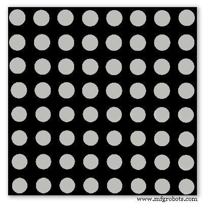
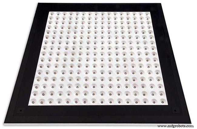
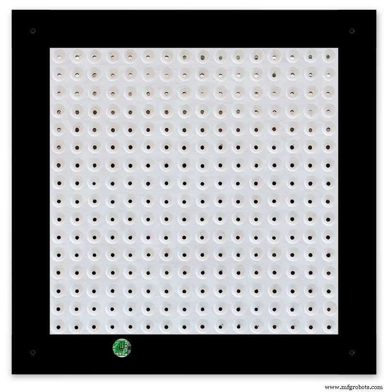
전면 보드에는 디스플레이의 개별 문자와 숫자를 밝히기 위해 6.5mm 구멍과 더 넓은 18mm 접시 구멍을 통해 빛나는 256개의 LED가 있습니다.
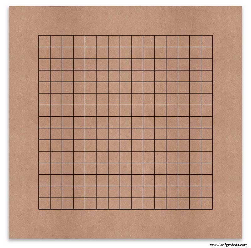
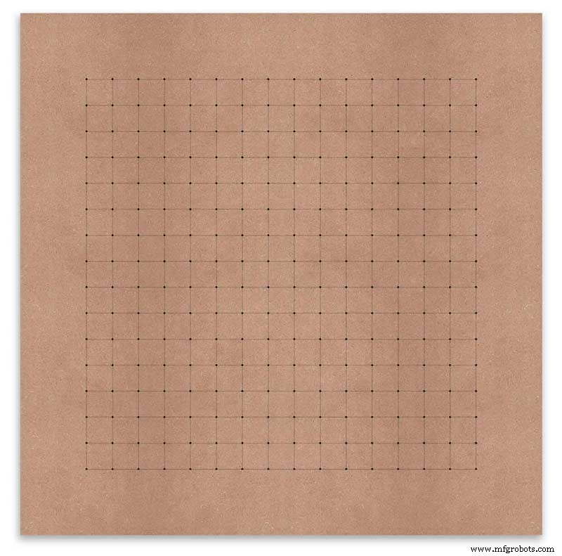
각 표시 문자의 중앙에 의 드릴 위치를 표시하도록 보드가 표시됩니다. 500mm 디스플레이를 사용하여 비닐 시트를 측정했으며 문자는 가장자리에서 62.5mm부터 시작하여 25mm 떨어져 있습니다. 저는 MDF에 이 선을 그렸고 교차점이 드릴링 포인트였습니다.
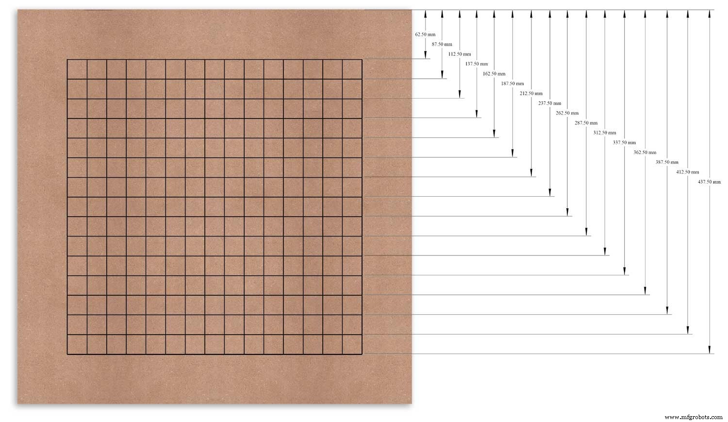
측정한 기준점으로 상단 가장자리를 사용하고 이 지점에서 각 행을 표시했습니다.
이것은 왼쪽 가장자리를 데이텀으로 사용하는 수직 기둥에 대해 반복되었습니다.
그리드의 교차점이 6mm LED 장착 구멍과 18mm 접시 구멍의 중심점이 됩니다.
Using an automatic centre punch ( use a nail or screw if you don't have one) I punched the 256 intersection points of the grid.
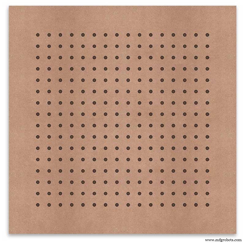
Using a drill bit to suite your LEDs (6mm in my case) and using the punched holes as a guide for the drill bit drill out all 256 LED mounting holes.
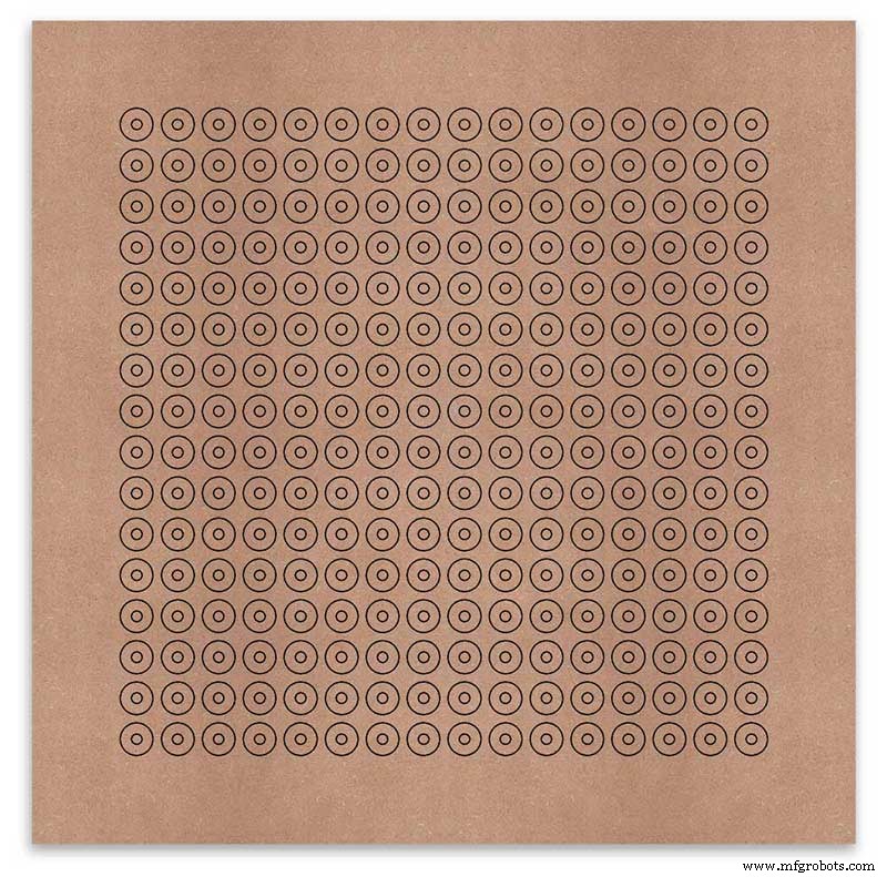
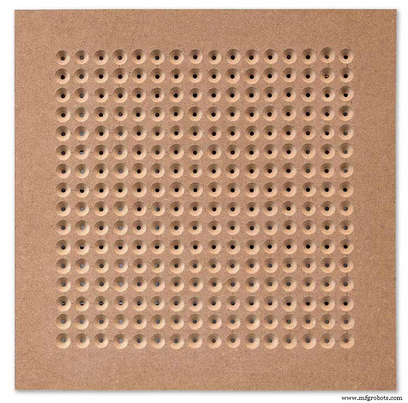
The next task is to drill the 256 18mm countersunk holes using a 20mm countersinking bit.
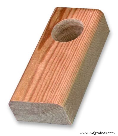
To keep the countersunk holes at a uniform depth and width I built a countersinking jig using an off cut of wood. To make the jig a hole is drilled in the wood off cut to just fit the silver rotating bezel of my drill chuck. Using a test piece of MDF the countersinking bit is then moved in and out of the chuck until a countersunk hole of the correct diameter is made when drilling through the hole upto the chuck in the off cut of wood. Once the correct distance is found the chuck is tightened and the main board is drilled 256 times by centring the hole in the wood over the existing 6mm holes then drilling down until the chuck bezel hits the hole in the countersinking jig.
Completed front board with 256 countersunk holes and 6mm holes for the LEDs.
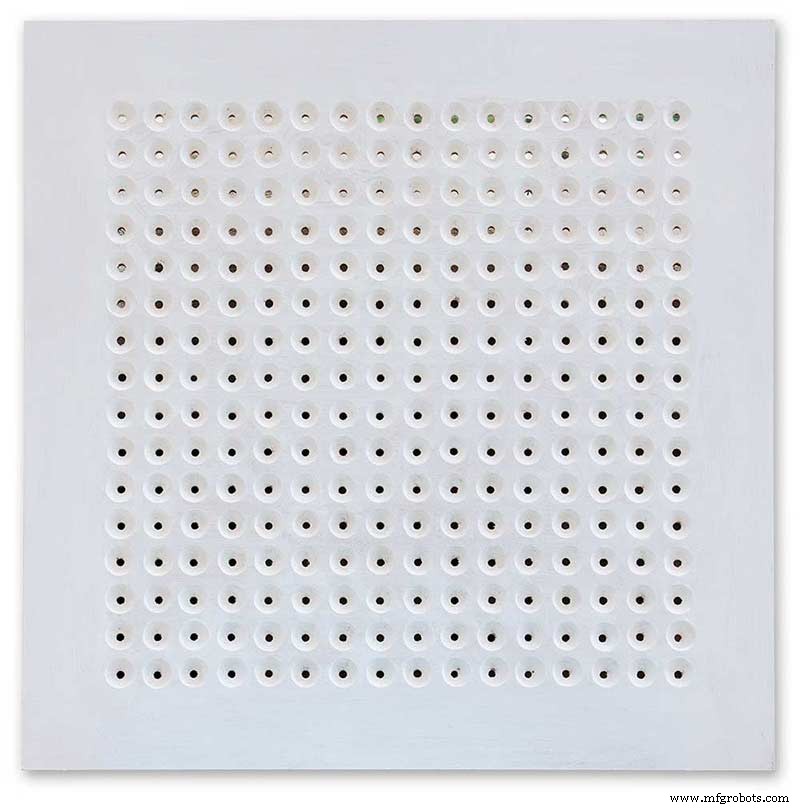
The board is then rubbed down and primed using MDF primer and painted white so the countersunk holes reflect the light from the LEDs.
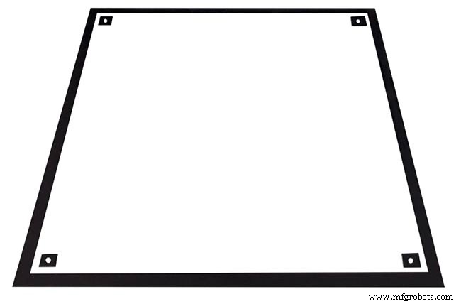
A black edge is painted around the outside edge to hide the board as the glass is 1mm shorter all round. This setback also helps the glass disappear from view on the final clock.
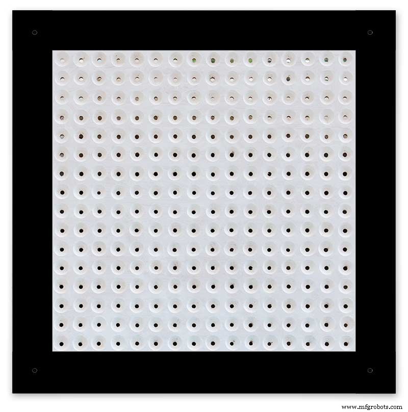
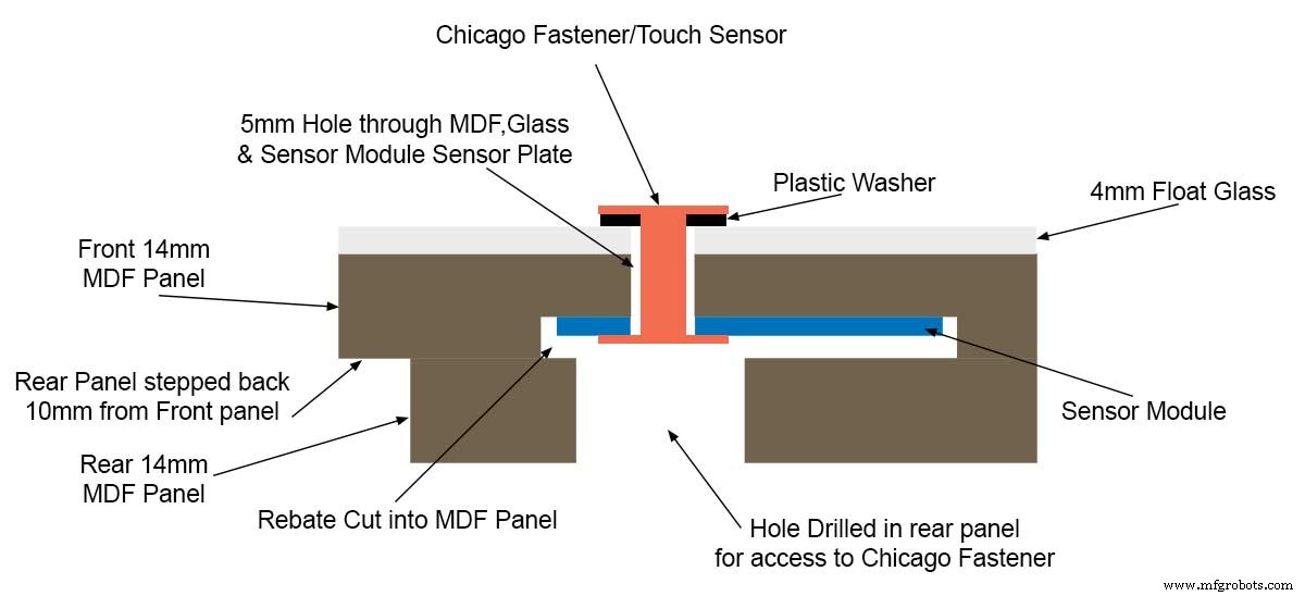
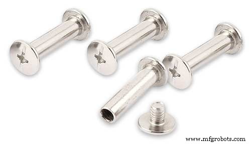
Four 5mm holes are then drilled in the corners to take the Chicago Fasteners. The Chicago Fasteners hold the glass in place, hold the touch sensors and provide a touch sensitive pad on top of the glass. The fasteners have 3mm shafts and will have a small bit of rubber tape wrapped around the shafts to protect the glass.
Turn the board over and drill a rebate with a forstner bit to take the four touch sensors. This hole will be offset from the hole drilled in the previous step.
Wall Mounts
The clock is fixed to the wall by two metal picture hanging mounts.
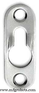
These are recessed into the frame so the highest point of the bracket is level with the frame.
Two 2" countersunk No6 screws sit in these bracket and hold the clock to the wall with a bit of tension so the dust seal is compressed.
Step 16:Construction Touch Sensor Mounting
The touch sensor modules are fixed to the front panel using the Chicago Fastener bolts. The Chicago Fastener bolts then act as touch sensors.
A 5mm hole is drilled through the sensor pad on the module to allow the Chicago Fastener bolt to pass through.
The sensor pad is insulated by the MDF panel and a plastic washer.
The touch pad on the sensor module has a 5mm mounting hole drill through the sensor.

Touch sensors in rebates behind rear panel. Holes drilled into rear panel allows access to the Chicago Fasteners that hold the sensors/glass front in place.
Clock front panel with four Chicago Fastener tops acting as touch plates.
Step 17:Electronic Components &Modules
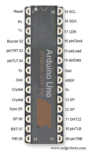
ATmega328 pin connections in case you want to prototype the circuit on an Arduino Uno. Note BST pin 07 is not used.
Pin label numbers refer to Arduino IDE numbers.
LEDs
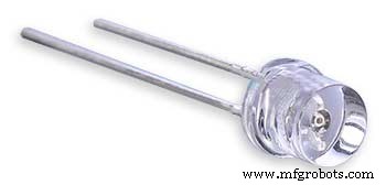
Make sure you purchase your LEDs from a good source. These LEDs will be on for many hours a day. I have has problems with LEDs failing after a few weeks use.
My LEDs Specs
5mm White Flat Top LEDs offering a pure and consistent colour with a wide angle ultra bright light output.
Colour :White
Quantity :256
Lenses Type :Round Flat Top
Crystal ClearBrightness :13000mcdForward
Voltage :3.2v - 3.8v
Forward Current :20mA (typical), 30mA (Max)
Viewing Angle :120 degrees
DHT22 Temperature &Humidity Sensor
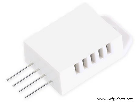
The DHT22 is a basic, low-cost digital temperature and humidity sensor. It uses a capacitive humidity sensor and a thermistor to measure the surrounding air, and sends out a digital signal on the data pin.
You can only get new data from it once every 2 seconds, so sensor readings can be up to 2 seconds old.
Simply connect the first pin on the left to 3-5V power, the second pin to your data input pin and the right most pin to ground.
To prevent the temperature of the inside clock case being measured the top and left side vent of the DH22 are covered over with tape. This also stops dust being drawn into the clock case.
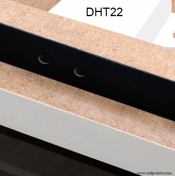
The DHT22 is mounted with its right open side mounted tight against the lower rear cover.Two small holes are drilled in the lower edge of the rear MDF board to allow air from the room to circulate around the sensor.
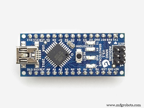
Arduino NANO
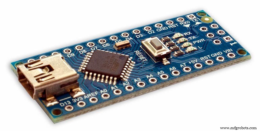
PowerThe Arduino Nano can be powered via the Mini-B USB connection, 6-20V unregulated external power supply (pin 30), or 5V regulated external power supply (pin 27). The power source is automatically selected to the highest voltage source.
Memory
The ATmega328 has 32 KB, (also with 2 KB used for the bootloader.
The ATmega328 has 2 KB of SRAM and 1 KB of EEPROM.
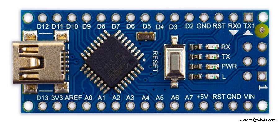
Input and Output
Each of the 14 digital pins on the Nano can be used as an input or output, using pinMode(), digitalWrite(), and digitalRead() functions. They operate at 5 volts. Each pin can provide or receive a maximum of 40 mA and has an internal pull-up resistor (disconnected by default) of 20-50 kOhms. In addition, some pins have specialized functions:Serial:0 (RX) and 1 (TX). Used to receive (RX) and transmit (TX) TTL serial data. These pins are connected to the corresponding pins of the FTDI USB-to-TTL Serial chip.
External Interrupts:2 and 3.
These pins can be configured to trigger an interrupt on a low value, a rising or falling edge, or a change in value. See the attachInterrupt() function for details.
PWM:3, 5, 6, 9, 10, and 11. Provide 8-bit PWM output with the analogWrite() function.
SPI:10 (SS), 11 (MOSI), 12 (MISO), 13 (SCK). These pins support SPI communication, which, although provided by the underlying hardware, is not currently included in the Arduino language.
LED:13. There is a built-in LED connected to digital pin 13. When the pin is HIGH value, the LED is on, when the pin is LOW, it's off.
The Nano has 8 analog inputs, each of which provide 10 bits of resolution (i.e. 1024 different values). By default they measure from ground to 5 volts, though is it possible to change the upper end of their range using the analogReference() function. Analog pins 6 and 7 cannot be used as digital pins. Additionally, some pins have specialized functionality:I2C:4 (SDA) and 5 (SCL). Support I2C (TWI) communication using the Wire library (documentation on the Wiring website).
There are a couple of other pins on the board:AREF. Reference voltage for the analog inputs. Used with analogReference(). Reset. Bring this line LOW to reset the microcontroller. Typically used to add a reset button to shields which block the one on the board.
Communication The Arduino Nano has a number of facilities for communicating with a computer, another Arduino, or other microcontrollers. The ATmega328 provide UART TTL (5V) serial communication, which is available on digital pins 0 (RX) and 1 (TX). An FTDI FT232RL on the board channels this serial communication over USB and the FTDI drivers (included with the Arduino software) provide a virtual com port to software on the computer. The Arduino software includes a serial monitor which allows simple textual data to be sent to and from the Arduino board. The RX and TX LEDs on the board will flash when data is being transmitted via the FTDI chip and USB connection to the computer (but not for serial communication on pins 0 and 1). A SoftwareSerial library allows for serial communication on any of the Nano's digital pins. The ATmega328 also support I2C (TWI) and SPI communication. The Arduino software includes a Wire library to simplify use of the I2C bus. To use the SPI communication, please see ATmega328 datasheet.
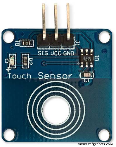
TTP223 Touch Sensor Module
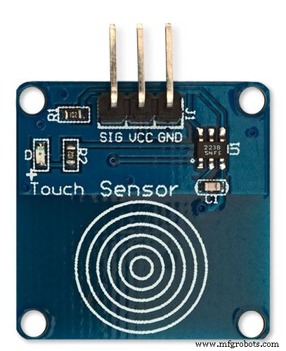
The touch Sensor Module is bolted to the front panel using the glass mounting bolts. The bolt goes through a 5mm hole drilled in the middle of the sensor.Note the mounting bolt is touched to trigger the sensor but is insulated from the sensor itself through plastic washers. Four of these modules are used in the clock one mounted on each corner of the glass.
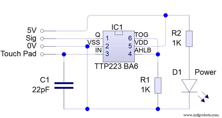
Note the LEDs are not required and are removed from the modules (just break them off) to save power.
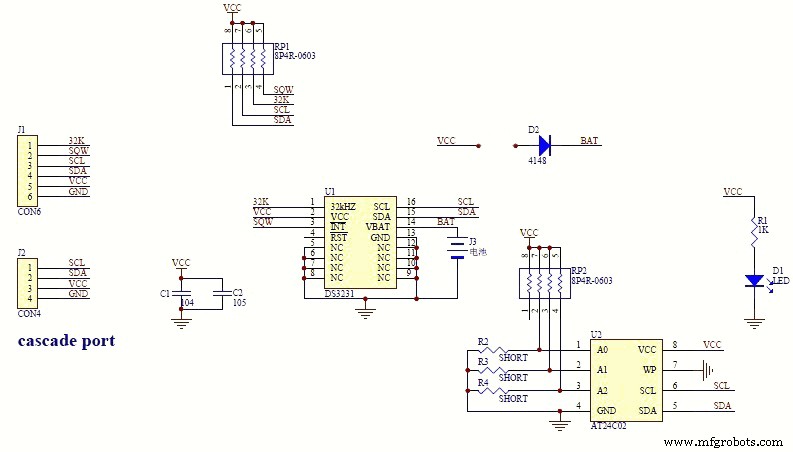
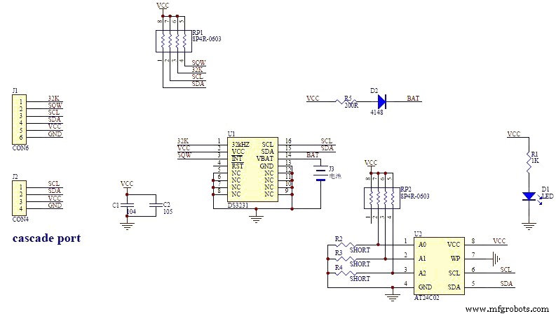
DS3231 AT24C32 I2C Precision Real Time Clock Module
My clock uses a DS3231 AT24C32 I2C Precision Real Time Clock Module.The module comes supplied with a Lithium-Ion rechargeable battery see diagram below. I use a non rechargeable battery so have removed resistor R5 from the module.
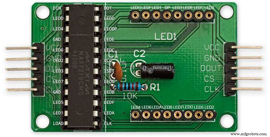
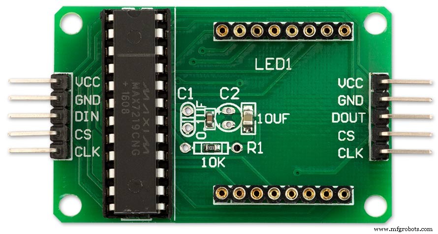
MAX7219 Display Module
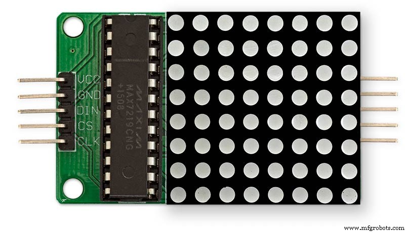
MAX7219 LED current limiting
The max current through the LEDs is set by a single resistor R1 on the module. The value of resistor can be found from the table below.
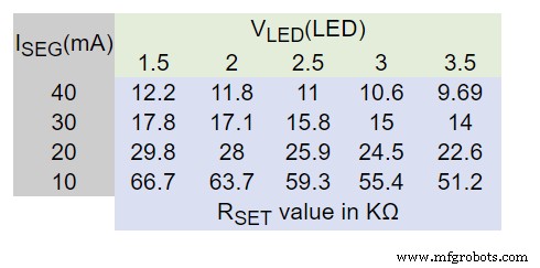
The module comes with a 10K resistor preinstalled but this can be removed and a resister to match your LEDs current added in its place. My LEDs Forward Voltage is 3.2v - 3.8v @ 20mA. They can handle 30mA max but for long LED life 20mA is best. I have used 22KΩ resistors which will limit the current to around 20mA when the light levels are at their peek.
See setting automatic brightness levels.
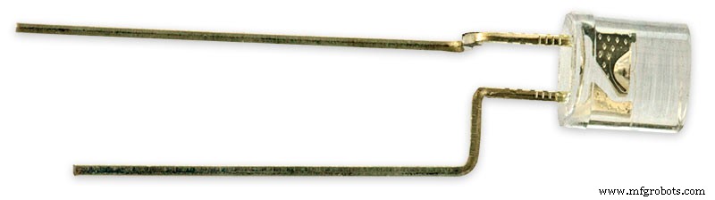
1088AS LED Dot Matrix display

1088AS LED Dot Matrix display view of lower edge Pins 1 to 8 left to right.
This is used for prototyping and is not required in the final project.
LDR
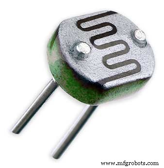
An LDR is used to sense the ambient light levels. The LDR is around 500Ω in bright light and 10MΩ in the dark.
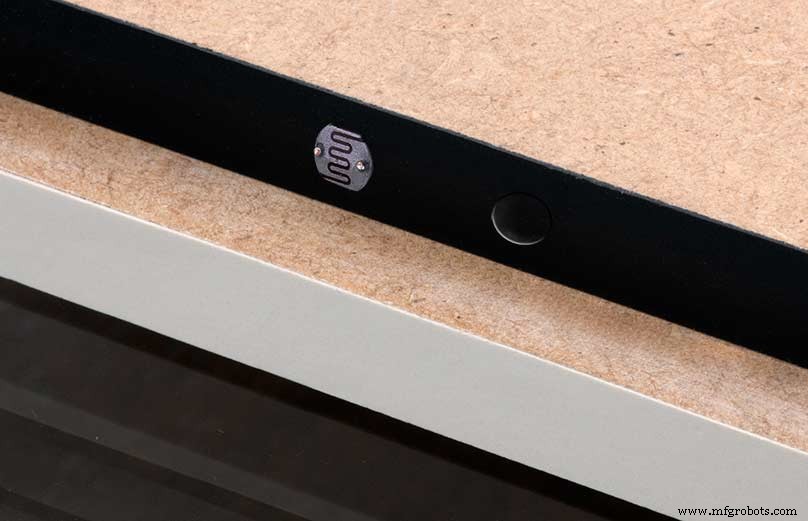
The LDR is positioned underneath the clock on the rear MDF panel.
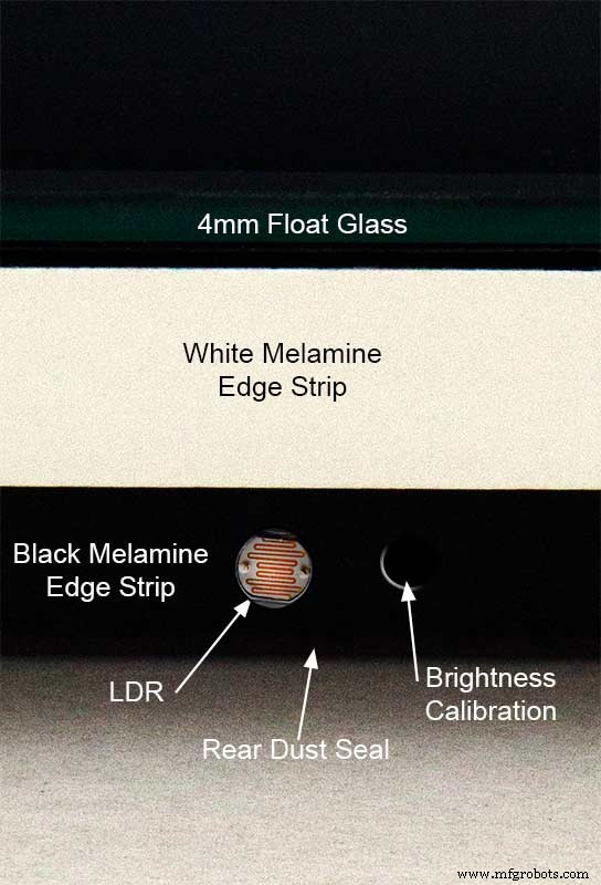
Next to the LDR is a hole to give access to the trimmer resister to calibrate the LED brightness control.
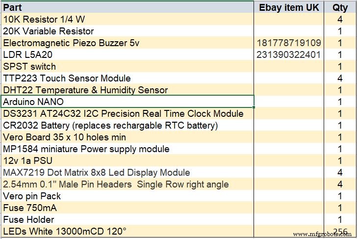
Component List
Step 18 Dust Seals
To prevent ingress of dust two dust seals are fitted.
On the rear MDF board a 2mm soft foam rubber dust seal is fitted. When the clock is hung on its hanging hooks the seal is under pressureand seals the back of the clock to the wall.
The seal is self adhesive and is fitted with a 5mm gap to the edge of the rear MDF board.
On top of the front board to prevent dust getting under the glass a strip of self amalgamating rubber is fitted 5mm from the board edge.
To prevent the glass from cracking when the Chicago bolts are tightened 4 small square of rubber are also fitted around the holes in the glass.
I punched holes for the Chicago Bolts in the rubber with a leather punch.
Step 19:Schematic
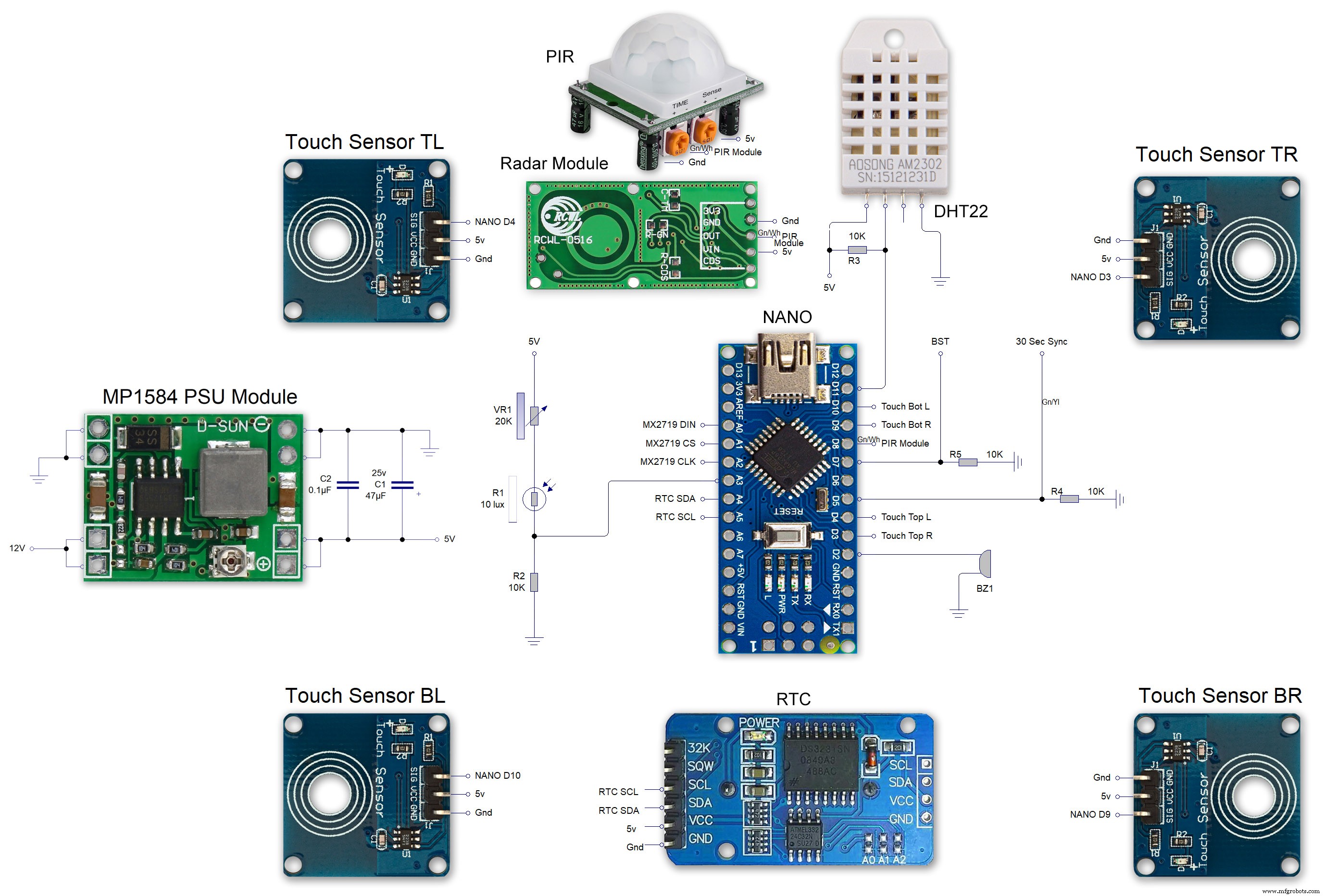
Nano Connections
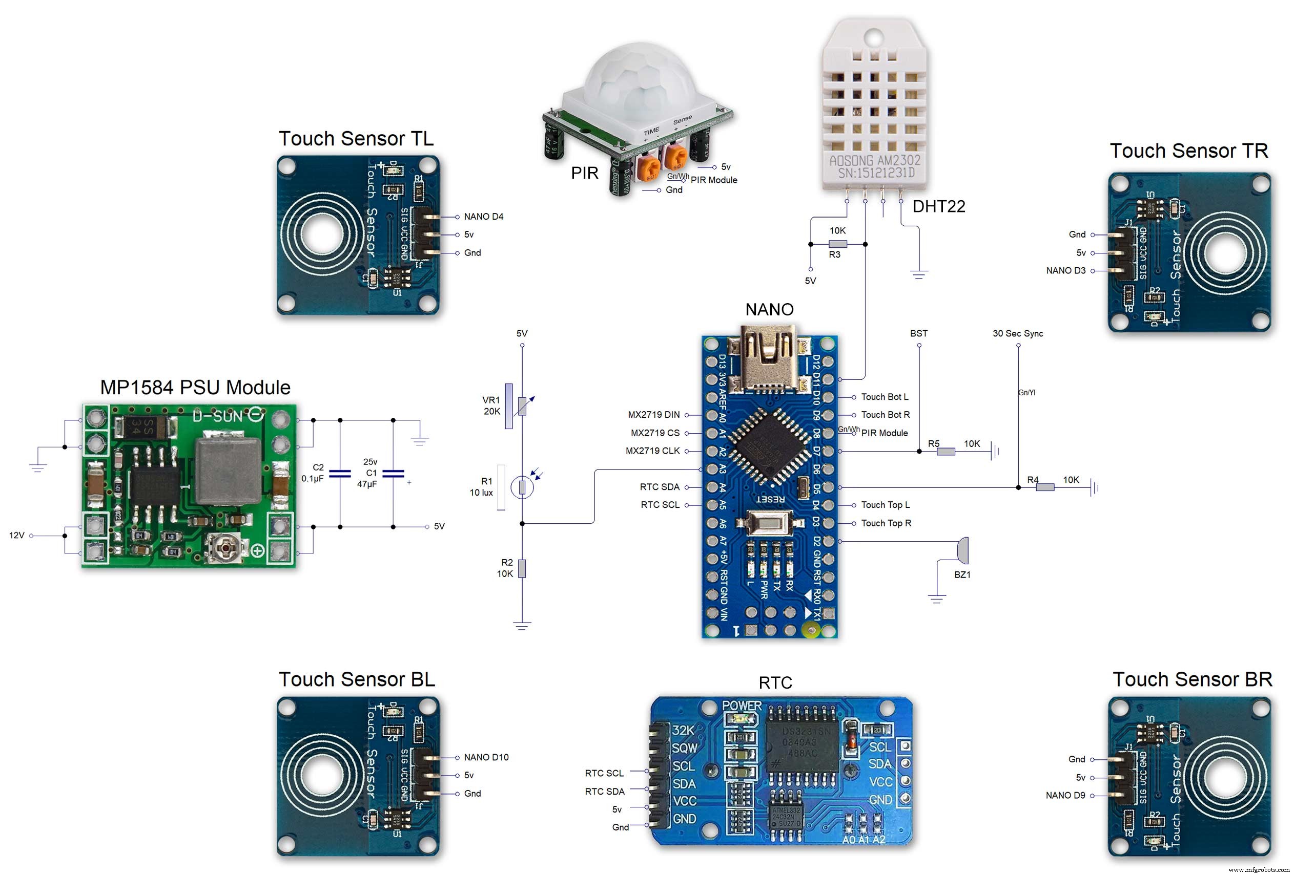
The connections to the Arduino Nano. Download the full size file from the hardware section
MAX2719 connections


The 4 MAX7219 modules and the connected LED matrixes.
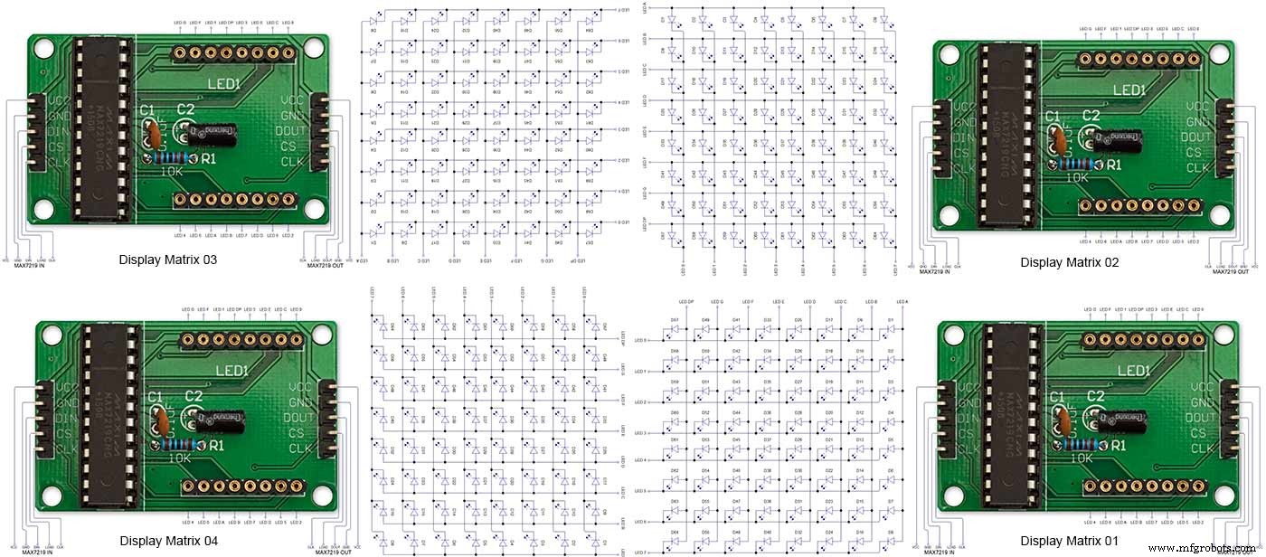
Note the LED display matrixes are rotated anti-clockwise 90 degrees from each other starting from display matrix 01.Display Matrix 01 input is wired to the Arduino CLK, DIN and LOAD the output is taken to the input of Display matrix 02 etc etc.
Step 20:Wiring Building the LED Matrixes
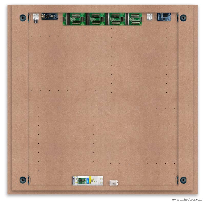
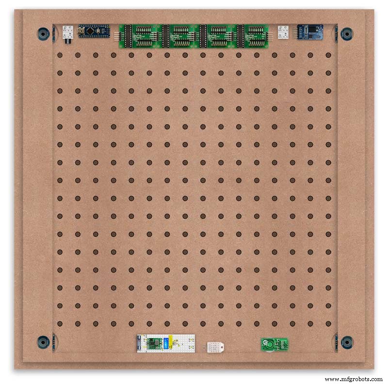
Module Locations

The module locations are shown above. The four sensors are located in the recesses on the main board behind the rear board. Holes are cut into the rear board to allow access for fit the Chicago Bolts/Sensor pads.
The four MAX7219 Display Modules are soldered together and are mounted in the centre top of the board. This keeps the data links between the boards as short as possible.
The Arduino Nano is mounted on the left of the MAX7219 Display Modules and the RTC on the right. The RTC battery holder on the base of the RTC module is recessed into the main board.
The Vero board containing the power module is located on the lower part of the board. There are two power distribution boards mounted on the top of the clock. The main 5v 2A feed cable is taken to both of these boards and power is then distributed to the other boards from these points.
The MAX7219 board power is fed from the left board and daisy chained through each board then taken out the forth board to ensure they are fed with 0v and 5v from both ends.
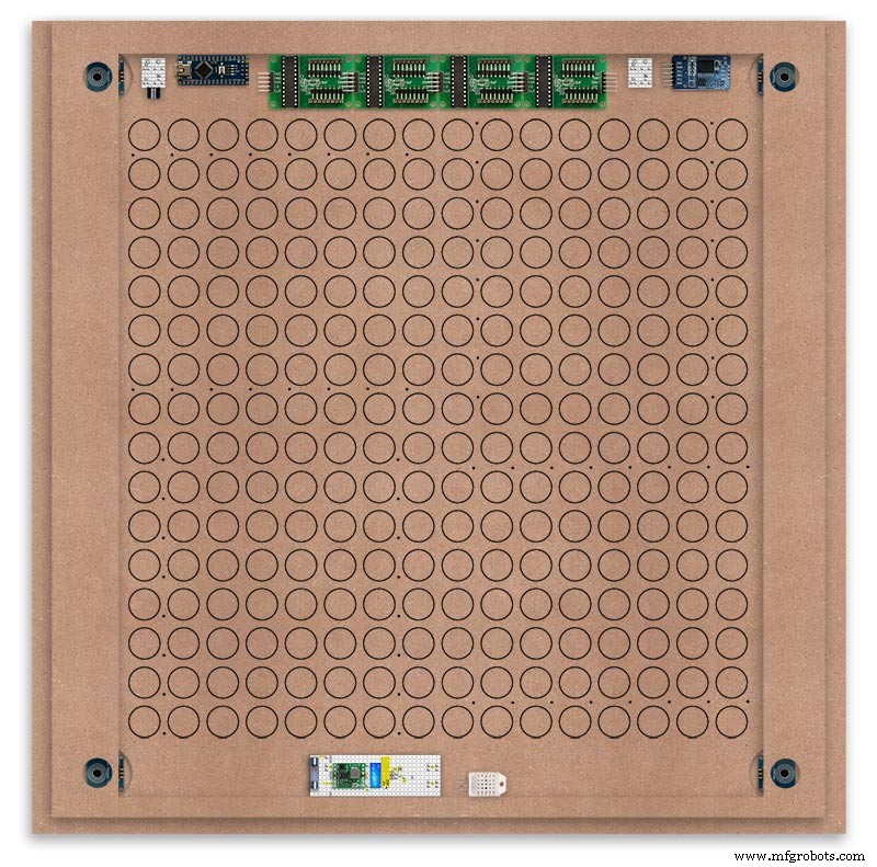
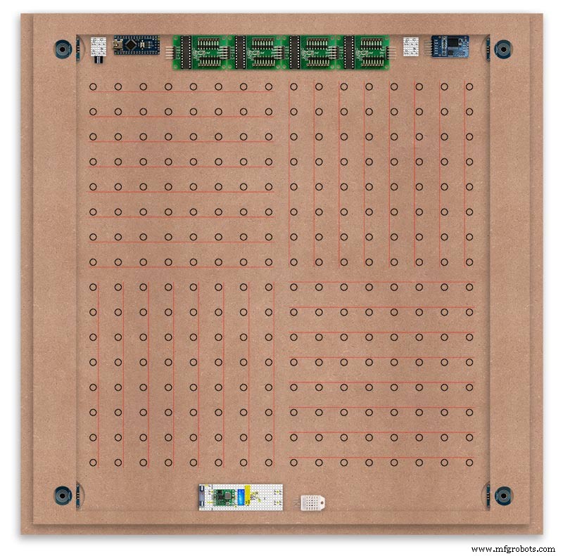
The LED locations are shown. The LED matrixes each contain 64 LEDs and are labelled 1 to 4.
These correspond to the 4 MAX 7219 modules mounted above numbered 1 to 4 left to right. Note this is the rear of the clock so number will be revearsed.
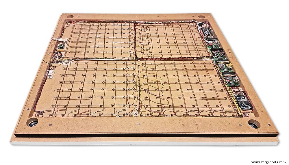
The LED Matrixes are built up off 2 types of BUS Bars per module. A Cathode Bus at 10mm high and an Anode BUS bar at 2mm high.
There are 8 Cathode and 8 Anode BUS Bars per module. Each module has 16 x 15mm panel pins hammered into the board in the position shown to support the 10mm high Cathode BUS.
The 15mm panel pins are hammered in 5mm (I used a 10mm piece of metal bar as a gauge) leaving 10mm as Cathode BUS bar support pins.
As shown above the pins correspond with the thick parts of the board not the recess for the LEDs on the front of the board. Note the LED recess is on the front of the board and can't be seen from the back.

0.9mm copper wire is then soldered to each pair of pins to form the Cathode BUS Bar.
Note the rotation of each module and also the modules are in reverse as it is the back of the board the LEDs are connected to.
The Anode BUS Bars are shown below in Red and are supported off each LED Anode about 2mm off the MDF board. No Pins required.

Both Cathode &Anode BUS Bar locations are shown below.
Each LED is connected to an Anode and Cathode of the Matrix.
Step 21:Wiring the LEDs
LEDs
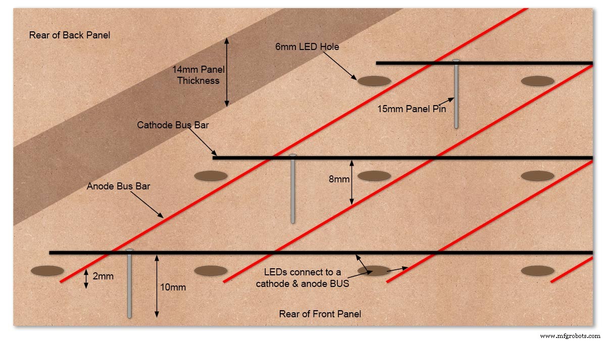
Diagram showing Bus Bar layout with panel pins supporting the Cathode Bus. This module has horizontal Cathode and vertical Anode Bus Bars.
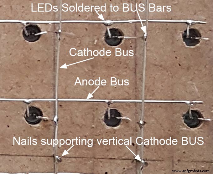
Close up section of Module wiring.The Cathode BUS Bars run vertically and the Anode BUS Bars run horizontally on this module. The Anode &Cathode BUS Bars have an 8mm vertical separation.
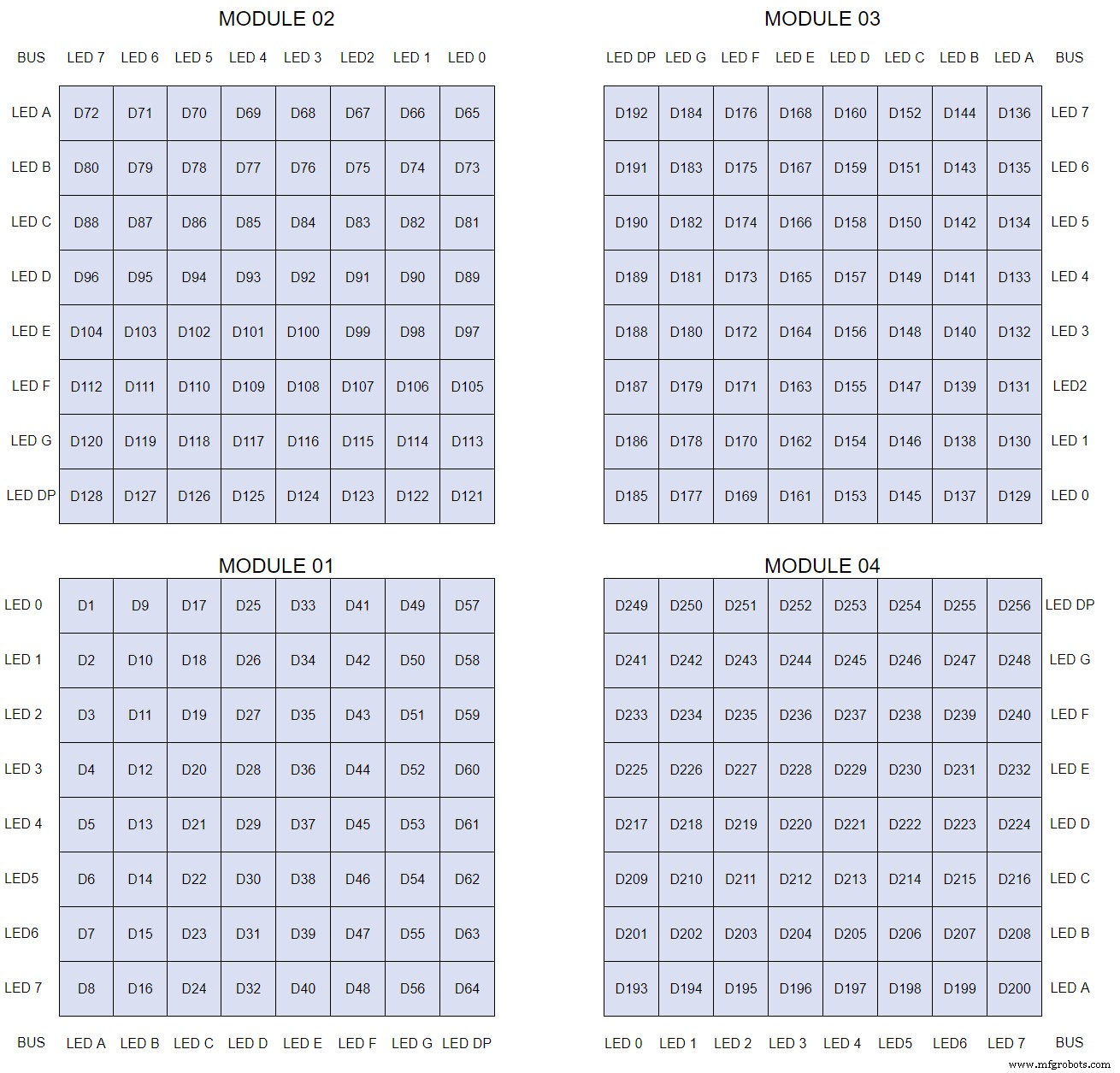
The LEDs are connected to the matrixes and MAX7219 modules from the rear. The LED positions will be reversed and of course rotated 90° relative to the next module. This makes it very complicated connecting the correct LEDs and Bus bars from the rear of the board. The table below shows the LED positions in the blue boxes with the BUS Bar matrix position in black around the outside as they appear from the back of the front MDF board.
The LEDs are bent in a jig to keep the position in the display constant and to speed up construction. Each LED has four bends two on each leg that's 1024 in total! The Cathode leg is bent 90° from the Anode.
The Matrix grids are wired to the corresponding pins on the MAX7219 modules according to the layout table.
There are 16 wires to each module.
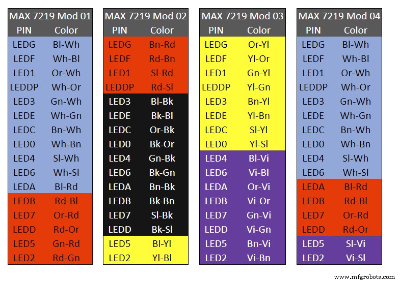
Table 1 Module LED Matrix Wiring Colour Code is shown above.
Each Module has 16 wires connecting it to the LED Matrixes. I have used 50pr 0.5mm cable so the last 14pr colours are duplicated. On Mod 4 I went out of order and missed out the Sl/Vi at the start so have put it in at the end.
Step 22:Wiring Modifying the MAX7219 Modules
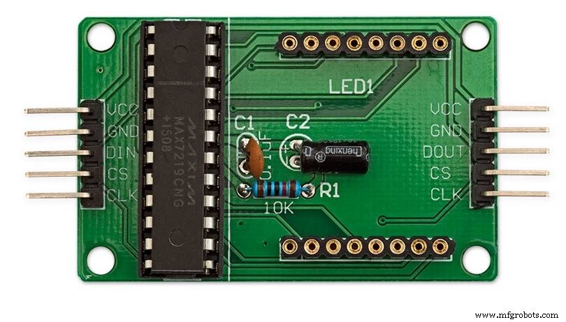
Before wires can be connected to the MAX 2917 modules they will need to be modified.
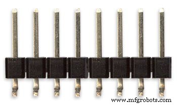
Two sets of 8 90° pin connectors will to be soldered to the lower edge of the existing LED matrix connector.

Modified MAX7219 module with 90° pin connectors soldered in place to the bottom of the old LED Matrix connectors.
Wires are taken away from these points to the LED matrix on the main MDF board as per the LED Matrix Wiring Colour Code table on the previous step.
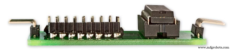
Side view showing the pins soldered to the side of the old LED Matrix connector pins just above the PCB.
Note if your MAX7219 Module does not have surface mount components the 90° pin connectors may need to be trimmed back so they don't foul R1, C1 or C2.
MAX7219 LED current limitingThe max current through the LEDs is set by a single resistor R1 on the module. The value of resistor can be found from the table below.

The module comes with a 10K resistor preinstalled but this can be removed and a resistor to match your LEDs current added in its place.
My LEDs Forward Voltage is 3.2v - 3.8v @ 20mA. They can handle 30mA max but for long LED life 20mA is best. I have used 22KΩ resistors which will limit the current to around 20mA when the light levels are at their peek.
Note this sets the max current through your LEDs actual brightness is controlled by the LDR/software/ trimmer resistor and will usually be far less than this.
Setting Automatic Brightness Levels
The clock automatically senses the ambient light and adjusts the LEDs accordingly.
When first installed the clock will need to be calibrated to the maximum light levels in its actual location.

Connect a mobile, laptop/tablet etc via a suitable cable to the mini USB port of the clock and open an app to monitor the serial port.
I use Slick USB 2 Serial Terminal on my S7 via an OTG cable and USB to mini USB cable.
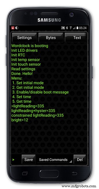
The clock will reboot and after the initial start screen you will see the following data updating down the screen.
You don't need to worry about lightReading or constrained lightReading+hyster just light reading, and bright.
With the clock in position and the ambient light at its maximum levels carefully insert a flat bladed jewellers screwdriver into the access hole just to the right of the light sensor.
Turn the screwdriver slowly until the light reading =600 (or your level set in brightness.cpp) and bright =15.
Your clock will now go to max brightness when the ambient light is at its maximum.
If you turn the screwdriver too far the light reading will go over 600 but the bright reading will not increase.
If you want the clock to be dimmer right across the range of ambient light levels adjust the light reading to a level less than 600 at max ambient light levels.
Note when bright=15 this will output the max current to the LEDs. The max current is set by R1( RSET) on the MAX7219 module and this should be chosen for your type of LED used in the display.
Step 23:Wring Mini USB Port
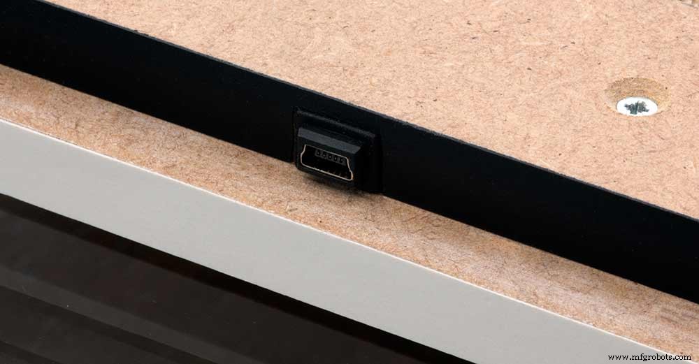
To allow adjustment/checking of light levels and programming of the clock a Mini USB socket is cut into the right hand side of the rear MDF sheet.
I have used a 25cm 90° Right angle Mini USB Male to Female Extension Cable and stripped back the insulation sleeve and shielding to expose the wires. This allows the cable to bend around the sharp angles and tight spaces of the enclosure.
Step 24:PIR Controlled Display Shutdown
This is optional as a Doppler Radar module can be fitted inside the clock instead.
See next section.
The PIR when enabled on the word clock menu (bott left PIR On, bott right PIR Off) turns on the display when movement is detected in the room.
When no movement is detected the display turns off after a set period of time. When the PIR is enabled the displays shows "PIR ON" and when disabled (display always on) it shows "PIR OFF" Note when the PIR is not enabled the display is always On.
The PIR module is fitted remote from the clock in a modified chrome light switch box. The box is cut into a plasterboard wall and also contains a switch to turn the clock off. The module itself is very small and can be mounted in a tiny enclosure if you don't want it on show. It will not work behind glass so if you wanted to mount it on the clock a hole would need to cut in the glass. This is very easy to do with a large hole cutter.
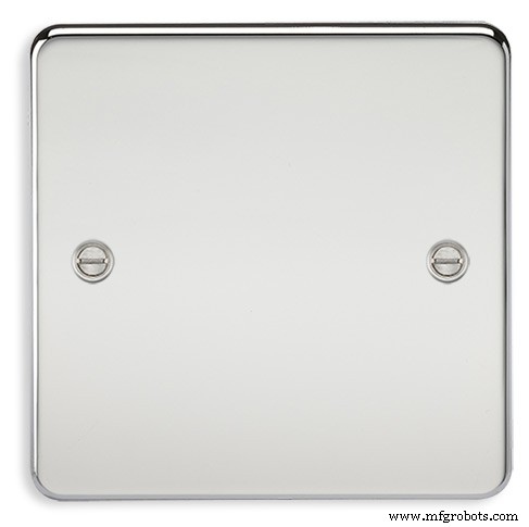
A blank chrome switch plate and back box are used to house the power switch and PIR module.
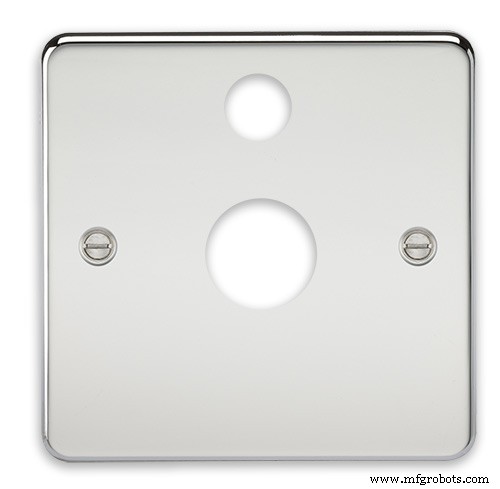
Two holes are drilled in the blank switch plate for the power switch and PIR lens.
The hole are centre punched, pilot drilled and then drilled out just big enough for a step cutter to fit through. The hole for the PIR diffuser is cut just big enough for the lens to go through with a friction fit.
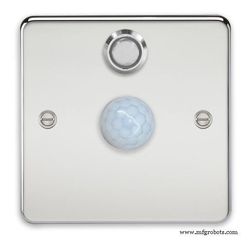
The completed switch plate.
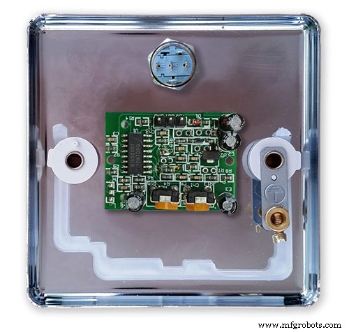
The 12 volt supply +ve is terminated on the switch with the 0v terminated on the earth screw.
12 volts is then fed back upto the clock PSU Vero board from the other side of the switch and again the earth screw. 5 volts are fed from the clock PSU Vero board to supply the PIR module.
The 5 volts and PIR sensor wire to the clock terminate on PCB header sockets. These are is plugged into the PIR Module header pins. The sync cable is terminated on a header pins and connects to the Master Clock 30 second sync cable via a single header socket.
The PIR has 2 trimmer resistors for adjusting sensitivity and also length of time the PIR &display stay activated.
PIR On/Off Control:The PIR is turned on and off in word clock mode by touching the bottom left sensor to turn the PIR on or by touching the right sensor to turn the PIR off. Note when the PIR is set to off the display stays on permanently. When you change the PIR setting the work "PIR ON" or "PIR OFF" is displayed for 5 seconds.
When initial power up the default is PIR off if you switch the PIR On straight away the display will go off as the PIR takes a minute or so to initialise before detecting movement.
Photo 6 &7 "PIR ON" or "PIR OFF" are displayed for 5 seconds when PIR setting is changed.
Step 25:Doppler Radar Control Option
Optional Doppler Radar Module can be added in place of the PIR above.
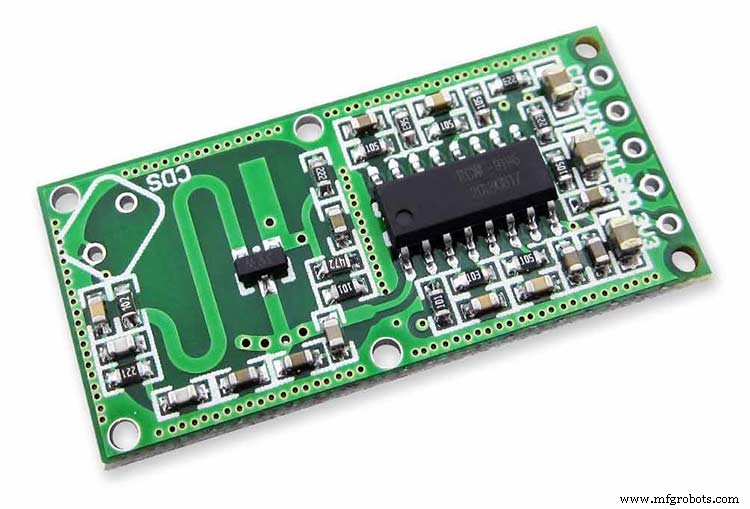
The Doppler Radar when enabled on the Word Clock menu (bott left PIR On, bott right PIR Off) turns on the display when movement is detected in the room. A check is made for motion on every quarter hour. When no movement is detected the display turns off until movement is detected again.
When the PIR is enabled the displays shows "PIR ON" and when disabled (display always on) it shows "PIR OFF" Note when the PIR is not enabled the display is always On. Unlike PIR modules the Doppler Radar module can see through glass and plastic and is fixed into the case of the clock behind the glass and PVC sticker. The module has a range of around 5m or 16' 5".
Doppler Radar Module fixed inside the case. A hole is drilled in the front panel to allow the module to monitor the room.
Front panel showing hole through to the Doppler Radar module microwave sensor.
The module is hidden from view behind the PVC sticker and glass.
Step 26:PIR/Doppler Radar On Off Control
The PIR is turned on &off in word clock mode by touching the bottom left sensor to turn the PIR on or by touching the right sensor to turn the PIR off.
Note when the PIR is set to off the display stays on permanently.

When you change the PIR setting the work "PIR ON" or "PIR OFF" is displayed for 5 seconds.
When initial power up the default is PIR off if you switch the PIR On straight away the display will go off as the PIR takes a minute or so to initialise before detecting movement.
Step 27:Setting Automatic Brightness Levels
The clock automatically senses the ambient light and adjusts the LEDs accordingly.
When first installed the clock will need to be calibrated to the maximum light levels in its actual location. Connect a mobile, laptop/tablet etc via a suitable cable to the mini USB port of the clock and open an app to monitor the serial port. I use Slick USB 2 Serial Terminal on my S7 via an OTG cable and USB to mini USB cable.

The clock will reboot and after the initial start screen you will see the following data updating down the screen.
You don't need to worry about lightReading or constrained lightReading+hyster just light reading, and bright.With the clock in position and the ambient light at its maximum levels carefully insert a flat bladed jewellers screwdriver into the access hole just to the right of the light sensor. Turn the screwdriver slowly until the light reading =600 (or your level set in brightness.cpp) and bright =15. Your clock will now go to max brightness when the ambient light is at its maximum. If you turn the screwdriver too far the light reading will go over 600 but the bright reading will not increase.
If you want the clock to be dimmer right across the range of ambient light levels adjust the light reading to a level less than 600 at max ambient light levels.
Note when bright=15 this will output the max current to the LEDs. The max current is set by R1( RSET) on the MAX7219 module and this should be chosen for your type of LED used in the display.
Step 28:Setting the Clock
The clock is set in the digital clock mode by touching the bottom left sensor.
The hour digits will now flash twice a second to indicate the clock is in time setting mode.In this mode the sensors have the following functions.
Top right - steps the hours or mins digits up
Top left- steps the hours or mins digits down
Bottom left 1sr press - enters the time setting mode selecting hours digits
Bottom left 2nd press -selects the mins digits for changing
Bottom left 3rd press -exits time setting mode and sets the time
Bottom right - resets the seconds to 00
Step 29:Synchronisation
If you have connected a 30 second master clock sync cable then the clock will jump back or forward to 30 seconds when out of time setting mode. If you don't have a Master Clock to sync to then the clock will fall back on the on board temperature compensated real time clock which in itself is a very precise quartz clock.
Just reset the seconds roughly in sync to the seconds (within 10 seconds either way) and wait for the clock to sync once out of time setting mode.
The animated loop below shows the Word Clock is running fast by several seconds. A synchronisation pulse is received from the Master Clock every 30 seconds on the minute and half minute synchronising the clock on 30 seconds.
The clock will ignore the 30 second synchronisation pulse from the Master Clock at 0 seconds. Note clock synchronisation only happens when the Word Clock is 20 seconds past and 20 seconds to a minute. In normal operation the sync pulse corrects the clock to within a fraction of a second so you will see the word "SYNC" appear with no visible correction to the seconds.
Note the synchronisation pulse is received every 30 seconds but the clock will ignore pulses at 0 seconds.
Step 30:Software &Making Changes
The software can be downloaded from the software tab and contains the following modules.
Program Files Modules
Brett_wordclock_v4_3.ino Main program, latest update includes shortened code saving 10% in size.
Thanks to srdevil for providing the updated code for this seconds display.
brightness.cpp/.h Brightness autoadjustment
character.cpp/.h Character (digit) definitions
credits.cpp/.h Ending Credits
display.cpp/.h Display &LED functions
life.cpp/.h Game of Life
serial.cpp/.h Serial port setup menu
simon.cpp/.h Simon Says game
temphum.cpp/.h Temperature &Humidity displa
tetris.cpp/.h Tetris game
time.cpp/.h Wordclock, digital clock
timeanalog.cpp/.h Analogue clock
touchbuttons.cpp/.h Touch buttons, mode switching
Third party libraries:
Chronodot.cpp/.h Chronodot library (for DS3231)
DHT.cpp/.h Temperature sensor library (for DHT22)
LedControl.cpp/.h LedControl library (for MAX7219)
stc.cpp/.h/platform.h Simple Tetris Clone library
pitches.h Note frequencies from the Arduino webpage
When you want to make changes to my code you can compare my code to the "Catalan Code" to make it easier to understand what changes you need to make. I have added //Brett to my code to highlight my changes.
Changing the code.
If like me you are not very good at coding just play around with the code to get an understanding of how it works.
I just save a different version each time I make even a tiny change. This way if I mess up I can go back a version and start again.
If you are keeping my linear seconds display update the version number on the display so you know what version you are trying out each time. This is done in the module credit.h around line 47.
It would take far too long to explain all the code but here is a very brief guide on how to change the words and when they are displayed.
The WORDS are set in time.h
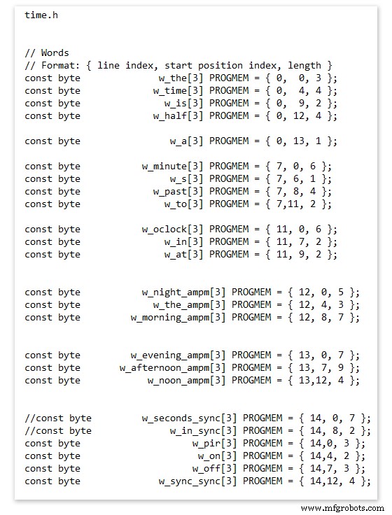
On line 52 we have
const byte w_the[3] PROGMEM ={ 0, 0, 3 };
The word "THE" is described in this line with the LED location in the curly brackets "{ 0, 0, 3 }"
This is the co-ordinate of the LEDs we are gong to light when we call "w_the"
The LED matrix numbers starts top left and start from 0 so "{ 0, 0, 3 }" is the first LED across and down the 3 just means the 3 LEDs across including this one will light. As the letters THE are in this position the word "THE" is displayed.
Similarly the word "TIME" would be lit by lighting the four LEDs here { 0, 4, 4 } or row 0, 5th LED along and light 4 LEDs (remember to count from 0).
Working you way down the page shows the position of all the words.
Controlling when words are lit
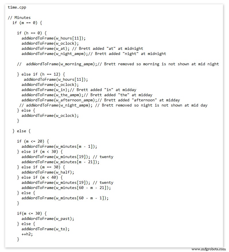
This happens in the module time.cpp
Here you just make a list of rules to tell the clock what words to light at certain times.
Pic above shows part of the code starting with line 695
At midnight we want to make the clock say "THE TIME IS TWELVE OCLOCK AT NIGHT"
Midnight is 00 00
"THE TIME IS" is always displayed from lines 687
So we add the rules if minutes are 0, then if hours are 0 show the word for hours "TWELVE" and the word "OCLOCK" the word "AT" and the word "NIGHT"
If you follow the code down all the possible time combinations are covered.
Analogue Clock Code Change - increase in time definition One of the comments sent to me by srdevil was some code changes. His comment can be seen below.
I have not had time to test the code but have included it below if you want to try it out.
" If the time is 18:00, it points up (long leg) and down (short leg). But when the time is 18:59, it still points totally down (short leg) so it looks like the time is 17:59 on a normal clock. My brother change the code so that if it is>HH:15 the small pointer moves already to the next number. As of this we also increased the resolution in the part between>HH:15 -
Code on the comments section or can be seen here http://home.btconnect.com/brettoliver1/Word_Clock/Word_Clock.htm#analogeclock
<섹션 클래스="섹션 컨테이너 섹션 축소 가능" id="코드">No preview (download only).
 MAX7219 7 segment display module 01 LED connections
 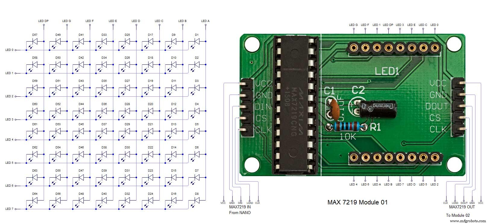 MAX7219 7 segment display module 02 LED connections
 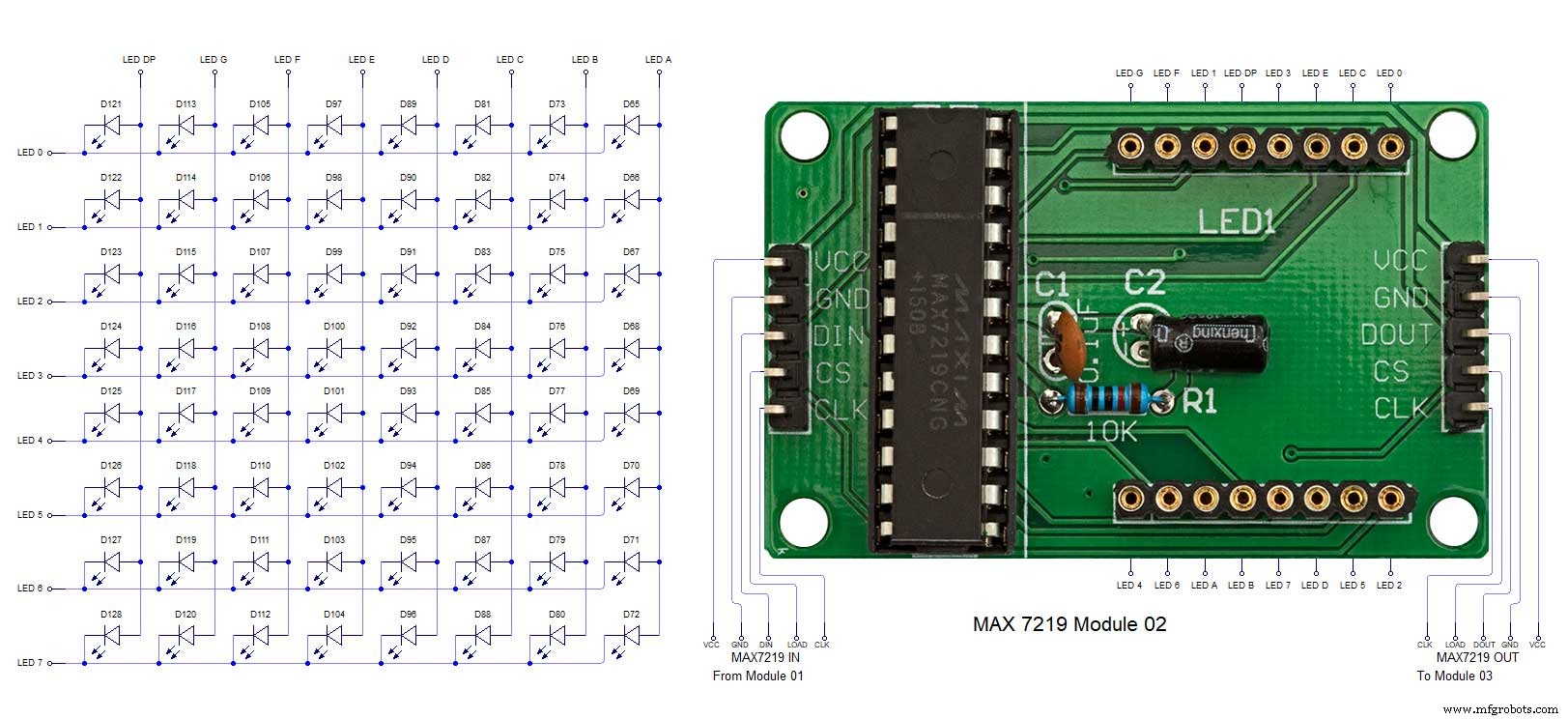 MAX7219 7 segment display module 03 LED connections
 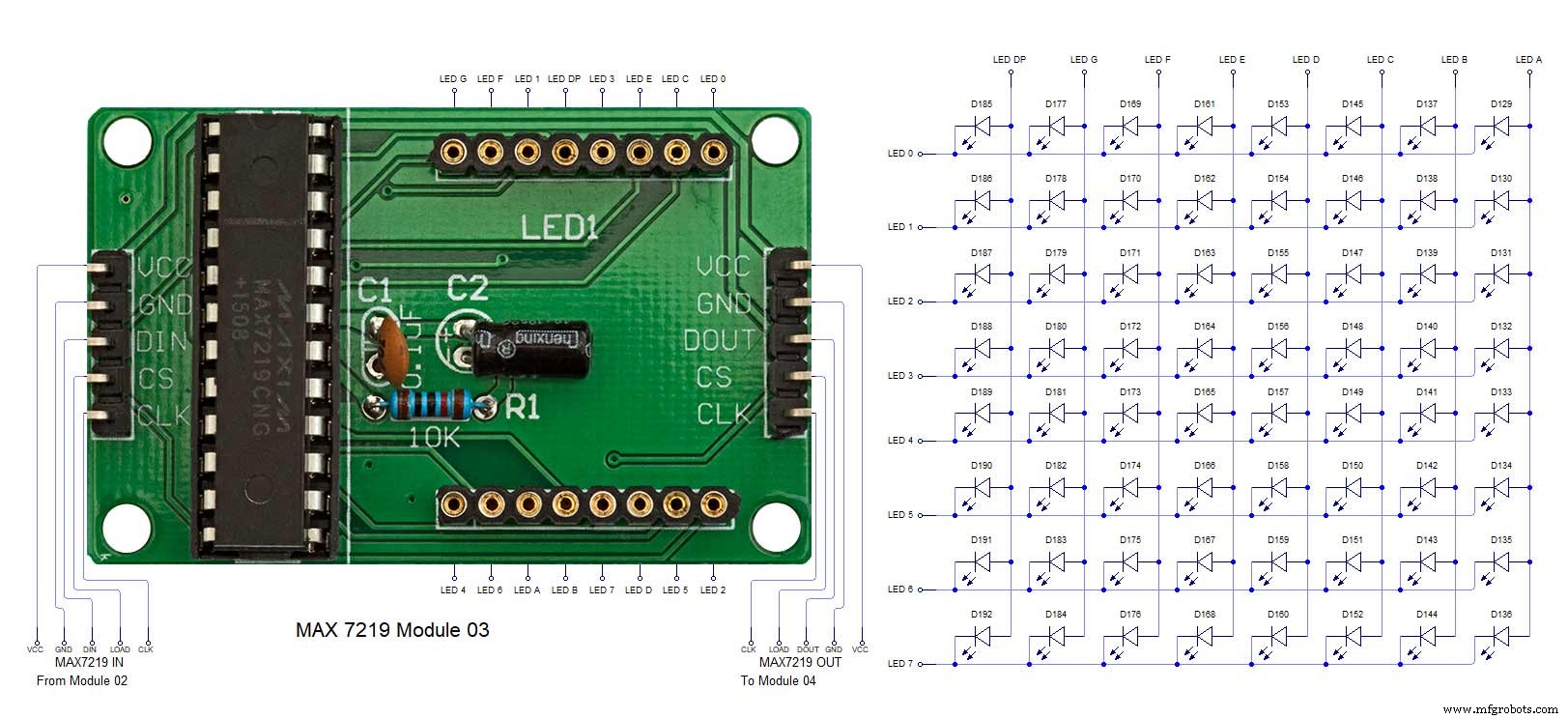 MAX7219 7 segment display module 04 LED connections
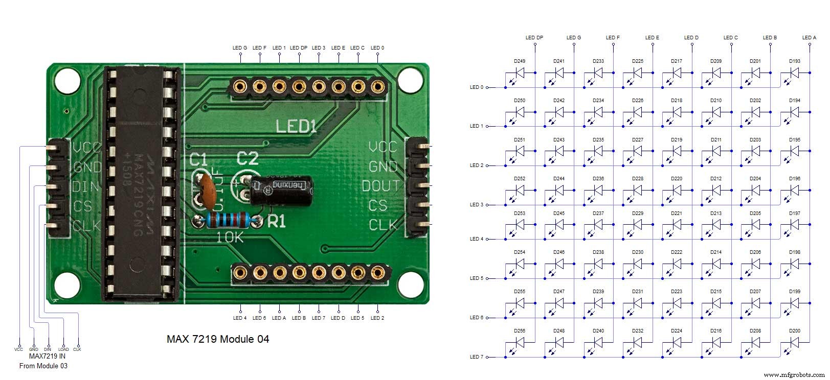
제조공정
오늘 누구에게나 이야기하면 인공 지능이 차세대 제품이라고 말할 것입니다. 모두가 한 조각을 원하지만 누구도 씹을 수 없는 뜨거운 감자입니다. 그들 중 상당수는 AI가 실제로 과대 광고에 불과하기 때문에 진행되는 많은 일에 대해서도 알려줄 것입니다. Powerpoint를 차려입은 오래된 기계 학습과 수학을 찬양하는 것입니다. 그리고 대부분 그들의 말이 맞을 것입니다. 그러나 딥 러닝과 같은 AI 도구의 적용이 혁신에 가까운 한 분야는 자연어 처리입니다. 쉬운 예는 웹사이트를 조작하는 챗봇입니다. LSTM(Long Short Te
CNC 기계에서 수동으로 공구를 교체하는 것은 결코 시기적절하거나 보람 있는 과정이 아닙니다. 일반적으로 표준 홀더의 도구 교체는 최대 5분이 소요됩니다. 이것을 몇 번 더하면 갑자기 제작 시간에 상당한 시간이 추가됩니다. CNC 공작 기계 및 절삭 공구 기술이 발전함에 따라 공구 교체를 방지하는 데 도움이 되는 더 많은 다기능 공구를 사용할 수 있습니다. 그러나 때로는 실현 불가능하고 여러 도구 변경이 필요합니다. 운 좋게도 Micro 100은 도구 변경 속도를 크게 높일 수 있는 혁신적이고 새로운 방법을 개발했습니다. Micr