/*
    Arduino and ADXL345 Accelerometer Tutorial
     by Dejan, https://howtomechatronics.com
*/

#include <Wire.h>  // Wire library - used for I2C communication

int ADXL345 = 0x53; // The ADXL345 sensor I2C address

float X_out, Y_out, Z_out;  // Outputs

void setup() {
  Serial.begin(9600); // Initiate serial communication for printing the results on the Serial monitor
  Wire.begin(); // Initiate the Wire library
  // Set ADXL345 in measuring mode
  Wire.beginTransmission(ADXL345); // Start communicating with the device
  Wire.write(0x2D); // Access/ talk to POWER_CTL Register - 0x2D
  // Enable measurement
  Wire.write(8); // (8dec -> 0000 1000 binary) Bit D3 High for measuring enable
  Wire.endTransmission();
  delay(10);
}

void loop() {
  // === Read acceleromter data === //
  Wire.beginTransmission(ADXL345);
  Wire.write(0x32); // Start with register 0x32 (ACCEL_XOUT_H)
  Wire.endTransmission(false);
  Wire.requestFrom(ADXL345, 6, true); // Read 6 registers total, each axis value is stored in 2 registers
  X_out = ( Wire.read()| Wire.read() << 8); // X-axis value
  X_out = X_out/256; //For a range of +-2g, we need to divide the raw values by 256, according to the datasheet
  Y_out = ( Wire.read()| Wire.read() << 8); // Y-axis value
  Y_out = Y_out/256;
  Z_out = ( Wire.read()| Wire.read() << 8); // Z-axis value
  Z_out = Z_out/256;

  Serial.print("Xa= ");
  Serial.print(X_out);
  Serial.print("   Ya= ");
  Serial.print(Y_out);
  Serial.print("   Za= ");
  Serial.println(Z_out);
}Code language: Arduino (arduino)
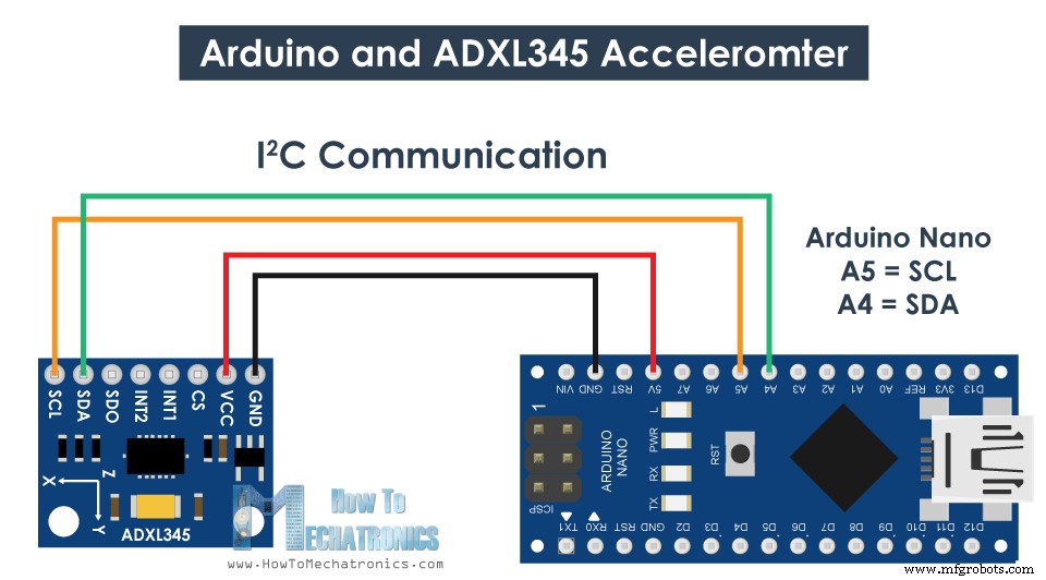
설명: 따라서 먼저 I2C 통신에 사용되는 Wire.h 라이브러리를 포함해야 합니다. I2C 통신이 작동하는 방식과 Arduino와 함께 사용하는 방법에 대한 자세한 내용은 제 다른 자세한 자습서를 참조하세요.
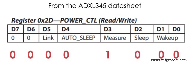
I2C 통신을 사용하는 각 장치에는 고유한 I2C 주소가 있으며 이 주소는 센서의 데이터시트(ADXL345 데이터시트)에서 찾을 수 있습니다. 따라서 설정 섹션에서 세 개의 출력에 대한 주소와 변수를 정의하면 먼저 와이어 라이브러리를 초기화한 다음 측정 모드에서 가속도계를 설정해야 합니다. 이를 위해 데이터시트를 다시 살펴보면 POWER_CTL 레지스터의 D3 비트를 HIGH로 설정해야 함을 알 수 있습니다.
<그림 클래스="aligncenter">
따라서 beginTransmission() 함수를 사용하여 통신을 시작한 다음 write() 함수를 사용하여 액세스하려는 레지스터를 말하고 다시 write() 함수를 사용하여 숫자 8을 작성하여 D3 비트를 HIGH로 설정합니다. 비트 D3 HIGH 설정에 해당하는 10진수.
// Set ADXL345 in measuring mode
  Wire.beginTransmission(ADXL345); // Start communicating with the device
  Wire.write(0x2D); // Access/ talk to POWER_CTL Register - 0x2D
  // Enable measurement
  Wire.write(8); // (8dec -> 0000 1000 binary) Bit D3 High for measuring enable
  Wire.endTransmission();Code language: Arduino (arduino)
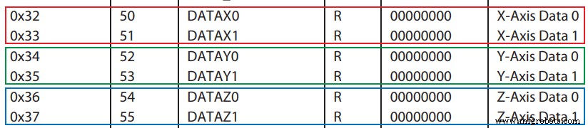
이제 루프 섹션에서 센서의 데이터를 읽습니다. 각 축의 데이터는 2바이트 또는 레지스터에 저장됩니다. 데이터시트에서 이러한 레지스터의 주소를 볼 수 있습니다.
그것들을 모두 읽기 위해 우리는 첫 번째 레지스터부터 시작하고 requestionFrom() 함수를 사용하여 6개의 레지스터를 읽도록 요청합니다. 그런 다음 read() 함수를 사용하여 각 레지스터에서 데이터를 읽고 출력이 2의 보수이므로 올바른 값을 얻기 위해 적절하게 결합합니다.
// === Read acceleromter data === //
  Wire.beginTransmission(ADXL345);
  Wire.write(0x32); // Start with register 0x32 (ACCEL_XOUT_H)
  Wire.endTransmission(false);
  Wire.requestFrom(ADXL345, 6, true); // Read 6 registers total, each axis value is stored in 2 registers
  X_out = ( Wire.read()| Wire.read() << 8); // X-axis value
  X_out = X_out/256; //For a range of +-2g, we need to divide the raw values by 256, according to the datasheet
  Y_out = ( Wire.read()| Wire.read() << 8); // Y-axis value
  Y_out = Y_out/256;
  Z_out = ( Wire.read()| Wire.read() << 8); // Z-axis value
  Z_out = Z_out/256;Code language: Arduino (arduino)
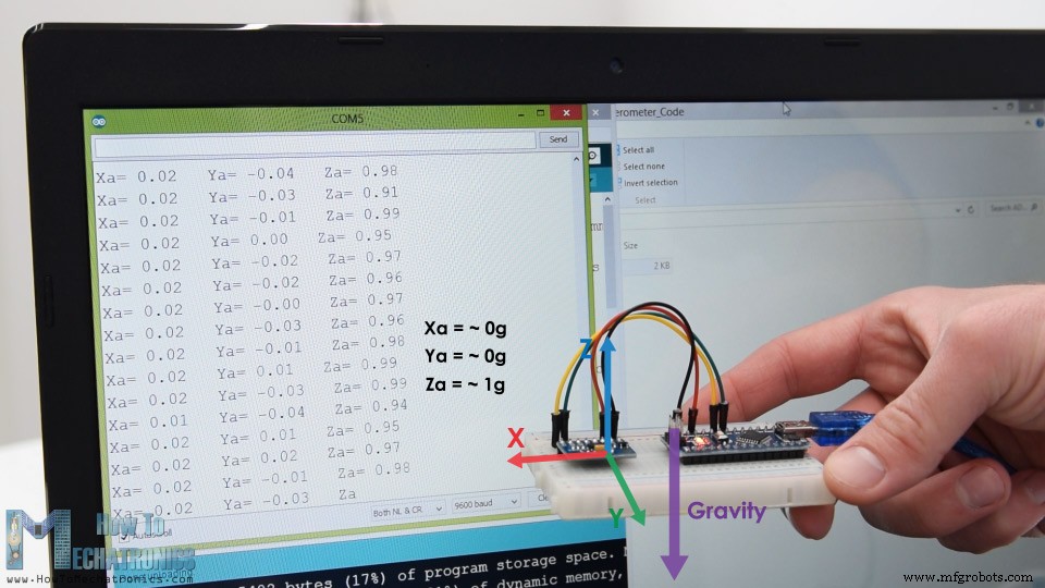
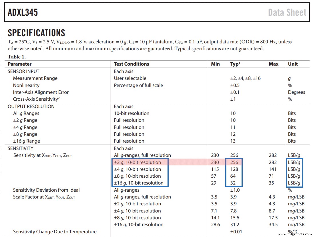
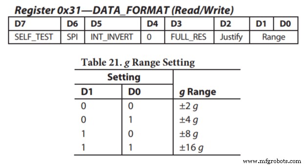
센서의 출력 값은 실제로 선택한 감도에 따라 달라지며, 이는 +-2g에서 +-16g까지 다양합니다. 기본 감도는 +-2g이므로 -1에서 +1g까지의 값을 얻으려면 출력을 256으로 나누어야 합니다. 256 LSB/g는 g당 256개의 카운트가 있음을 의미합니다.
애플리케이션에 따라 적절한 감도를 선택할 수 있습니다. 이 경우 추적 방향의 경우 +-2g 감도가 좋지만 급격한 움직임, 충격 등과 같이 더 높은 가속력을 감지해야 하는 응용 프로그램의 경우 DATA_FORMAT 레지스터를 사용하여 다른 감도 범위 중 일부를 선택할 수 있습니다. D1 및 D0 비트.
<그림 클래스="aligncenter">
ADXL345 가속도계 보정
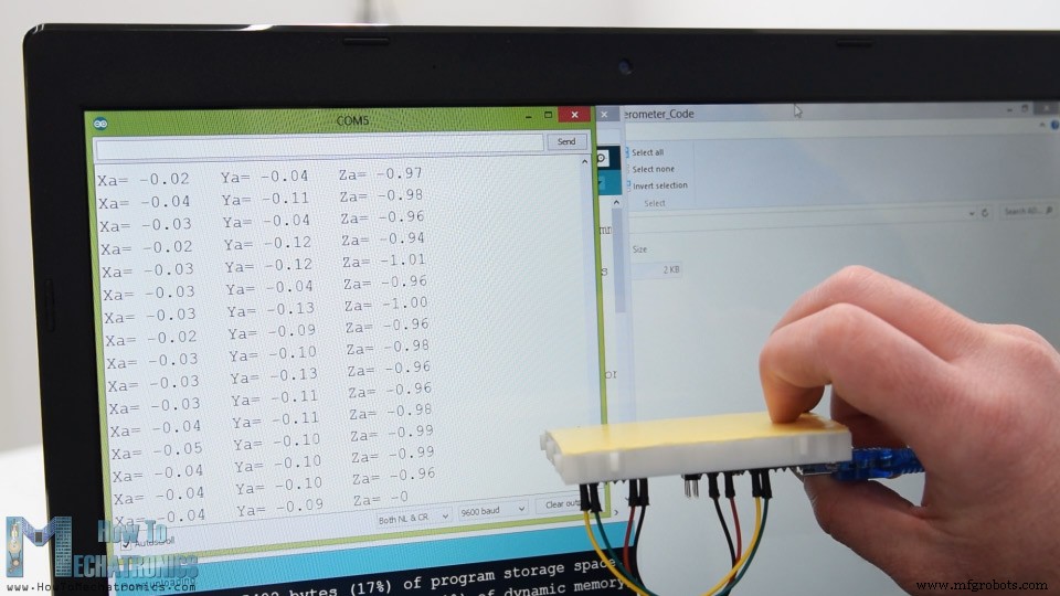
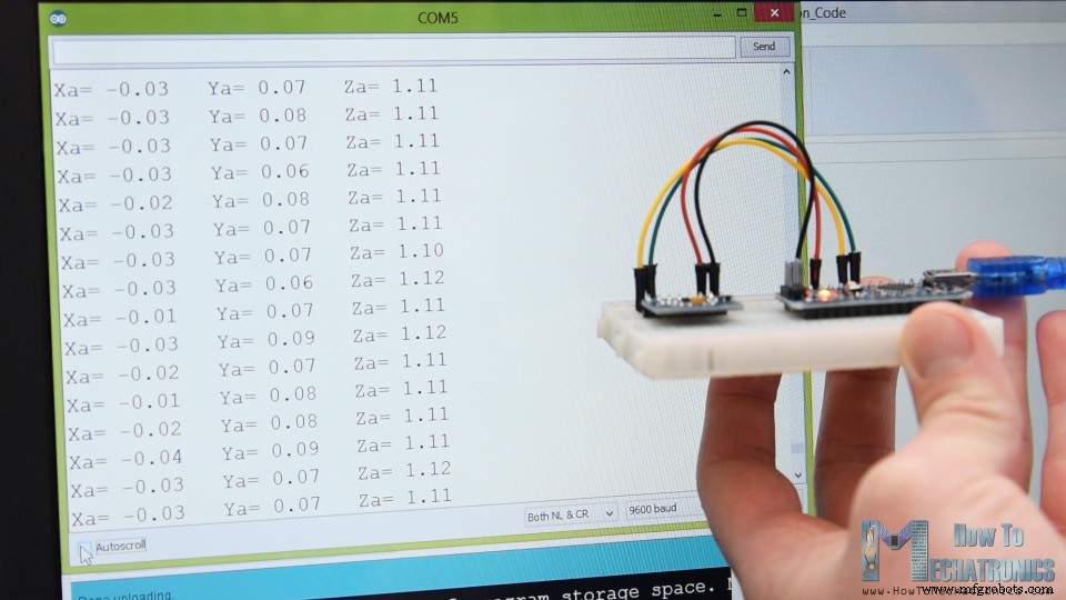
그럼에도 불구하고 데이터를 읽은 후에는 직렬 모니터에 인쇄하여 값이 예상한 대로인지 확인할 수 있습니다. 제 경우에는 얻은 값이 정확히 정확히 일치하지 않았습니다. 특히 Z축에는 0.1g의 눈에 띄는 오류가 있었습니다.
이 문제를 해결하려면 3개의 오프셋 보정 레지스터를 사용하여 가속도계를 보정해야 합니다. 이를 수행하는 방법은 다음과 같습니다. 따라서 센서를 평평하게 배치하고 RAW 값을 256으로 나누지 않고 인쇄해야 합니다.
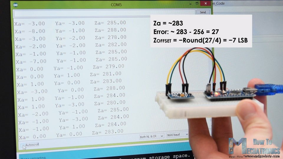
이제 여기에서 출력이 얼마나 꺼져 있는지 알 수 있습니다. 제 경우 Z 출력은 약 283이었습니다. 양수에서 27의 차이입니다. 이제 우리는 이 값을 4로 나누어야 합니다. 그러면 Z축 오프셋 레지스터에 쓰는 데 필요한 숫자가 사용됩니다. 지금 코드를 업로드하면 Z축 출력은 정확히 256 또는 1g가 되어야 합니다.
필요한 경우 동일한 방법을 사용하여 다른 축을 보정해야 합니다. 그리고 이 보정이 레지스터에 영구적으로 기록되지 않는다는 점에 유의하십시오. 센서를 켤 때마다 이 값을 레지스터에 기록해야 합니다.
보정이 완료되면 이제 이 두 공식을 사용하여 롤 및 피치, 즉 X축을 중심으로 한 회전과 Y축을 중심으로 한 회전을 도 단위로 계산할 수 있습니다.
// Calculate Roll and Pitch (rotation around X-axis, rotation around Y-axis)
  roll = atan(Y_out / sqrt(pow(X_out, 2) + pow(Z_out, 2))) * 180 / PI;
  pitch = atan(-1 * X_out / sqrt(pow(Y_out, 2) + pow(Z_out, 2))) * 180 / PI;Code language: Arduino (arduino)
이러한 공식의 작동 방식에 대한 자세한 내용은 이 Freescale Semiconductor 애플리케이션 노트를 참조하십시오.
Arduino 및 ADXL345 가속도계 방향 추적 – 3D 시각화
자, 이제 가속도계 3D 시각화 예제를 만들어 보겠습니다.
따라서 직렬 포트를 통해 Roll 및 Pitch 값을 보내는 동일한 코드를 사용하고 있습니다. 전체 Arduino 코드는 다음과 같습니다.
/*
    Arduino and ADXL345 Accelerometer - 3D Visualization Example
     by Dejan, https://howtomechatronics.com
*/
#include <Wire.h>  // Wire library - used for I2C communication

int ADXL345 = 0x53; // The ADXL345 sensor I2C address

float X_out, Y_out, Z_out;  // Outputs
float roll,pitch,rollF,pitchF=0;

void setup() {
  Serial.begin(9600); // Initiate serial communication for printing the results on the Serial monitor

  Wire.begin(); // Initiate the Wire library
  // Set ADXL345 in measuring mode
  Wire.beginTransmission(ADXL345); // Start communicating with the device
  Wire.write(0x2D); // Access/ talk to POWER_CTL Register - 0x2D
  // Enable measurement
  Wire.write(8); // Bit D3 High for measuring enable (8dec -> 0000 1000 binary)
  Wire.endTransmission();
  delay(10);

  //Off-set Calibration
  //X-axis
  Wire.beginTransmission(ADXL345);
  Wire.write(0x1E);
  Wire.write(1);
  Wire.endTransmission();
  delay(10);
  //Y-axis
  Wire.beginTransmission(ADXL345);
  Wire.write(0x1F);
  Wire.write(-2);
  Wire.endTransmission();
  delay(10);

  //Z-axis
  Wire.beginTransmission(ADXL345);
  Wire.write(0x20);
  Wire.write(-9);
  Wire.endTransmission();
  delay(10);
}

void loop() {
  // === Read acceleromter data === //
  Wire.beginTransmission(ADXL345);
  Wire.write(0x32); // Start with register 0x32 (ACCEL_XOUT_H)
  Wire.endTransmission(false);
  Wire.requestFrom(ADXL345, 6, true); // Read 6 registers total, each axis value is stored in 2 registers
  X_out = ( Wire.read() | Wire.read() << 8); // X-axis value
  X_out = X_out / 256; //For a range of +-2g, we need to divide the raw values by 256, according to the datasheet
  Y_out = ( Wire.read() | Wire.read() << 8); // Y-axis value
  Y_out = Y_out / 256;
  Z_out = ( Wire.read() | Wire.read() << 8); // Z-axis value
  Z_out = Z_out / 256;

  // Calculate Roll and Pitch (rotation around X-axis, rotation around Y-axis)
  roll = atan(Y_out / sqrt(pow(X_out, 2) + pow(Z_out, 2))) * 180 / PI;
  pitch = atan(-1 * X_out / sqrt(pow(Y_out, 2) + pow(Z_out, 2))) * 180 / PI;

  // Low-pass filter
  rollF = 0.94 * rollF + 0.06 * roll;
  pitchF = 0.94 * pitchF + 0.06 * pitch;

  Serial.print(rollF);
  Serial.print("/");
  Serial.println(pitchF);
}Code language: Arduino (arduino)
이제 Processing 개발 환경에서 이러한 값을 수신하고 이를 사용하여 생성할 3D 개체를 회전해야 합니다. 전체 처리 코드는 다음과 같습니다.
/*
    Arduino and ADXL345 Accelerometer - 3D Visualization Example
     by Dejan, https://howtomechatronics.com
*/

import processing.serial.*;
import java.awt.event.KeyEvent;
import java.io.IOException;

Serial myPort;

String data="";
float roll, pitch;

void setup() {
  size (960, 640, P3D);
  myPort = new Serial(this, "COM8", 9600); // starts the serial communication
  myPort.bufferUntil('\n');
}

void draw() {
  translate(width/2, height/2, 0);
  background(33);
  textSize(22);
  text("Roll: " + int(roll) + "     Pitch: " + int(pitch), -100, 265);

  // Rotate the object
  rotateX(radians(roll));
  rotateZ(radians(-pitch));

  // 3D 0bject
  textSize(30);
  fill(0, 76, 153);
  box (386, 40, 200); // Draw box
  textSize(25);
  fill(255, 255, 255);
  text("www.HowToMechatronics.com", -183, 10, 101);

  //delay(10);
  //println("ypr:\t" + angleX + "\t" + angleY); // Print the values to check whether we are getting proper values
}

// Read data from the Serial Port
void serialEvent (Serial myPort) {
  // reads the data from the Serial Port up to the character '.' and puts it into the String variable "data".
  data = myPort.readStringUntil('\n');

  // if you got any bytes other than the linefeed:
  if (data != null) {
    data = trim(data);
    // split the string at "/"
    String items[] = split(data, '/');
    if (items.length > 1) {

      //--- Roll,Pitch in degrees
      roll = float(items[0]);
      pitch = float(items[1]);
    }
  }
}Code language: Arduino (arduino)
설명: 따라서 여기에 직렬 라이브러리를 포함하고 직렬 포트와 업로드된 Arduino 스케치의 전송 속도와 일치해야 하는 전송 속도를 정의해야 합니다. 그런 다음 들어오는 데이터를 읽고 적절한 롤 및 피치 변수에 넣습니다. 기본 그리기 루프에서 이 값을 사용하여 3D 개체를 회전합니다. 이 경우에는 특정 색상과 텍스트가 있는 단순한 상자입니다.
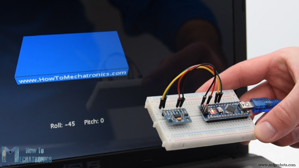
스케치를 실행하면 3D 개체가 나타나고 가속도계 센서의 방향을 추적합니다. 여기서 물체가 실제로 약간 흔들리고 있음을 알 수 있습니다. 이는 가속도계가 중력뿐만 아니라 손의 움직임에 의해 생성되는 작은 힘도 포착하기 때문입니다. 더 부드러운 결과를 얻기 위해 간단한 저역 통과 필터를 사용할 수 있습니다. 여기에서 Arduino 코드에서 이러한 필터를 구현했는데 이전 상태의 94%를 취하고 현재 상태 또는 각도의 6%를 추가합니다.