

제조공정

산업 제조
고로 제철의 진화
최초의 철 제련의 기원은 기록되지 않은 인류 문명의 역사에 숨겨져 있습니다. 고대에 철 도구가 사용되었다는 첫 번째 증거는 실제로 이집트에서 피라미드의 두 돌 사이의 접합부에서 철 도구가 발견되었습니다. 많은 선사 시대 철 도구의 기원은 아마도 운석 철이었을 것입니다. 운석 철은 5% ~ 26%의 니켈(Ni)을 포함하는 반면 제련 철은 미량의 Ni만 포함하므로 유성으로 만든 철 인공물은 제련된 철의 물체와 구별할 수 있습니다.
4,000여 년 전에 사람들은 운석 철을 발견했습니다. 그러나 채굴된 철광석에서 철 생산이 시작되기까지는 또 다른 2,000년이 걸렸습니다. 인도에서 제련된 철의 최초 발견은 기원전 1800년(통용 시대 이전)으로 거슬러 올라갑니다. 철의 제련은 기원전 1500년경에 히타이트 제국의 신민인 아르메니아의 칼리브인들 사이에서 일어났다고 합니다. 그들의 제국이 기원전 1200년경에 무너졌을 때, 다양한 부족들은 그들과 함께 제철 지식을 가져갔고, 그것을 유럽과 아시아 전역에 퍼뜨렸습니다. 모든 유럽과 서아시아의 제철 지식은 궁극적으로 이 출처에서 유래했습니다. 철기 시대는 철 제련의 발견으로 시작되었습니다.
철 제련 시작
황화구리 광석의 환원과 마찬가지로 산화철의 첫 번째 환원은 아마도 우연이었을 것입니다. 이 고대 야금학자(당시 광부, 화학자, 기술자)는 단순한 용광로에서 산화물 광석의 탄소(C) 환원을 통해 철을 생산할 수 있다는 사실을 깨닫게 된 것은 관찰의 힘이었습니다. 제련 과정에 대한 최초의 기록된 묘사는 기원전 1500년경 이집트 무덤의 벽에서 발견되었습니다. (그림 1) 이 과정은 발로 작동되는 벨로우즈를 사용하여 화재를 심화시킨 광석과 미지의 연료가 있는 단순한 구덩이였습니다. 이후 3000년 동안 철 생산 기술은 산화물의 C 환원으로 생산된 철 스펀지와 스펀지를 두드려 만든 철 제품으로 크게 변하지 않았습니다.
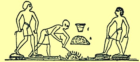
그림 1 이집트 무덤에 묘사된 철 제련 과정
산화철 광석은 지구의 많은 지역에 존재하므로 이집트에서 철광석의 환원이 일어나고 있는 것과 거의 동시에 다른 지역에서도 이루어지고 있었습니다. 인도, 중국, 아프리카 및 말라야는 이 초기 제철 관행의 개발 현장이었습니다. 이들 국가에서 개발된 용광로는 모두 매우 유사했습니다. 모양과 크기에는 차이가 있었지만 용광로는 기능적으로 동일했습니다. 철로의 화학적 환원은 녹지 않고 일어나며, 그 결과 금속은 비교적 순도가 높고 부드러우며 이를 연철이라 하였으며 두드려 유용한 모양으로 만들 수 있었다. 연철.
약 2000년 동안 서기 천년기(통용 시대)가 끝날 때까지 철은 '블루머리' 공정을 통해 지역의 작은 화로에서 생산되었습니다. 고고학적 조사에서는 이러한 구조의 크기를 알 수 없지만 현대식으로 재건된 블루머리 용광로는 내부 치수가 직경 300mm였습니다. x 1000mm 높이. 개화 과정에서 화로가 만들어지고 마운드가 만들어질 때까지 숯과 철광석을 여러 층으로 배치했습니다. 이 둔덕 주위에는 점토와 벽돌로 된 케이싱이 만들어졌으며 상단에는 배기 가스를 위한 구멍이 있고 하단에는 벨로우즈를 작동하여 생성된 공기 폭발을 위한 구멍이 있습니다. 그런 다음 목탄에 불을 붙이고 목탄이 소진될 때까지 벨로우즈를 작동했습니다. 그런 다음 케이싱을 부수고 공정이 잘 진행되면 해면철 더미와 슬래그 웅덩이가 생겼습니다. 뜨거운 해면철을 망치로 두드려 철 빌렛이나 철 제품을 생산했습니다. 블루머리 과정에서 제련 중에 일어나는 반응이 여기에 설명되어 있습니다. 숯불은 일산화탄소(CO)를 생성하고 열은 늪지 광석에서 물을 몰아내고 적철광을 생성합니다. CO는 적철광을 산화제1철(wüstite)로 환원시켰다. 그런 다음 CO는 wüstite를 원소 철로 환원합니다. 반응은 끝까지 진행되지 않았습니다. 평형 위치로 진행하여 생성된 가스는 CO와 이산화탄소(CO2)의 혼합물이었습니다. 그러나 wüstite는 또한 어떤 모래와도 반응하여 생산된 슬래그의 주요 구성요소인 철 감람석(fayalite)을 생성할 수 있습니다. 이 파얄라이트는 용광로 조건에서 원소 철로 환원될 수 없기 때문에 제련 공정에 관한 한 막다른 골목이었습니다. 생산된 철의 녹는점은 약 100%였습니다. 섭씨 1,540도, 슬래그의 융점은 약 1,100도였습니다. 도달한 온도는 슬래그를 녹일 만큼 높았지만 철을 녹일 만큼 높지는 않았습니다. 남아 있는 슬래그에는 종종 60% 이상의 FeO(산화철)가 많이 포함되어 있지만 공정은 충분히 잘 작동했습니다. 슬래그는 부분적으로 늪지 광석 드로스의 개방형 다공성 특성과 적색 철광석에서 얻은 것과 같이 부분적으로 조밀하고 단단하며 매우 불용성인 두 가지 종류가 있습니다.
제철 공정의 발전
이 첫 번째 제철 공정은 제련 구멍을 돌과 진흙으로 채우고 나무와 가죽으로 만든 풀무를 사용하여 개선되었습니다(그림 2). 중국에서 철의 사용은 기원전 600년경에 나타나 기원전 403년에서 기원전 222년 사이에 널리 퍼졌습니다. 중국인은 우수한 제철 기술을 개발했으며 주철 도구의 발견을 기반으로 기원전 200년에 액체 철이 생산되었습니다. 중국과 인도의 고대 문헌에는 철 제련이 언급되어 있습니다. 다른 유물에는 칼, 도끼, 낫, 괭이가 있습니다. CE 310까지 충분한 양의 철이 생산되어 인도의 델리와 다르의 유명한 철 기둥을 세울 수 있었습니다. 델리의 연철 기둥은 높이 18m, 지름 410mm, 무게 17톤입니다. 일본에서는 '타타라'로 알려진 전통적인 제강 공정이 17세기까지 완전히 개발되지 않았습니다. 북미, 남미 및 호주에서는 철 제련이 고대 주민들에게 알려지지 않았습니다. 제철 기술은 유럽인들에 의해 이들 국가에 도입되었습니다.
지중해 주변에서 발달한 제철 공정은 유럽을 통해 북쪽으로 퍼졌습니다. 페니키아인, 켈트인, 로마인은 제철 기술의 보급을 도왔습니다. 로마인들이 북쪽으로 대영제국까지 퍼뜨린 제철 기술 중 하나는 초기 사발 또는 화로였습니다. 이 용광로는 사발 모양의 용기 또는 언덕 측면에 건설된 2m 높이의 원통형 샤프트로 구성되었습니다. 용광로 내부의 불을 부채질하는 데 사용되는 공기는 일반적인 바람을 마주하는 그릇 바닥 근처에 만들어진 구멍에 의해 제공되었습니다. 용광로는 상단 개구부를 통해 하부 개구부를 통해 점화된 목탄과 철광석 층으로 채워졌습니다.
철 제련이 어떻게 진행되었는지에 대한 두 가지 이론이 있습니다. 하나는 공정을 가열하는 공기를 제공하는 하단 개구부를 통해 불어오는 바람과 다른 하나는 개방된 상단 위로 바람이 불어 내부 전면 벽을 따라 저압 영역을 생성하는 것입니다. 아래쪽 구멍을 통해 공기를 흡입했습니다(그림 2). 두 경우 모두 그 과정은 바람에 의존했고 일년 내내 신뢰할 수 없었습니다. 제품은 다시 한 번 해면철 덩어리로, 아래쪽 구멍을 통해 제거한 다음 망치로 두드려 최종 형태로 만들었습니다.
초기 철 제련소의 또 다른 유형은 벌집 용광로였습니다(그림 2). 이 용광로는 평평한 땅에 목탄과 철광석을 번갈아 쌓아서 건설했습니다. 토루는 두꺼운 점토층으로 덮여 있었고 벨로우즈와 연결된 송풍관은 아래쪽 측벽을 통해 삽입되었습니다. 목탄의 바닥 층에 불이 붙고 압축 공기가 벨로우즈에 의해 제공되었습니다. 이 회분식 제련이 끝나면 점토 돔이 무너졌습니다. 생산된 해면철은 망치질을 위해 철거된 벌집 용광로에서 파냈습니다. 이 용광로에서 생산되는 것은 작은 철 덩어리였으며 제련 용광로는 각 생산 가동 후에 철거 및 재건되어야 했습니다.
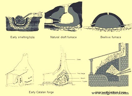
그림 2 제철의 초기 과정
이러한 유형의 제철 공정은 많은 개선 없이 현대에 이르기까지 수백 년 동안 사용되었습니다. 그 후 대략 8세기에 스페인 북동부의 카탈로니아 산에서 운영되는 작은 단조 공장이 제철 분야의 초기 야금술 발전 중 하나를 나타냈습니다. 초기 카탈루냐 대장간(그림 2)에는 높이가 약 910mm이고 직경이 760mm인 난로라고 하는 돌로 만든 컵이 있습니다. 베이스 전면에서 짧은 거리에는 송풍구로 알려진 노즐을 설치할 수 있는 작은 구멍이 있었습니다. 송풍구 노즐은 공기 공급을 위해 벨로우즈에 연결되었습니다. 화로에는 숯 덩어리가 송풍구 수준까지 채워졌습니다. 그런 다음 철광석을 풍구 위에 놓고 그 위에 더 많은 목탄을 쌓았습니다. 목탄에 불을 붙이고 벨로우즈에서 나오는 공기가 뜨거운 CO를 광석 위로 밀어넣어 철광석을 뜨겁고 덩어리진 철 덩어리로 환원시켰습니다. 블룸으로 알려진 철 덩어리는 최대 160kg까지 나갈 수 있으며 석조 구조물을 파괴하지 않고 집게로 대장간에서 제거할 수 있습니다. 이 양의 철은 5시간 만에 생산할 수 있는 반면 이전 기술은 5시간 만에 약 23kg만 생산할 수 있었습니다. 카탈루냐 대장간은 이후 200년 동안 규모가 증가했으며 프랑스, 벨기에, 영국 및 독일로 그 사용이 확대되었습니다. 난로의 크기는 1m 정사각형으로 증가했으며 직사각형 석재 블록으로 만들어졌습니다. 송풍구를 통해 전달되는 공기의 양도 '트롬프'로 알려진 공기 흡입기를 사용하여 증가되었습니다. 물이 트롬프 기둥을 통해 떨어지면 공기가 튜브로 빨려들어간 다음 상자 바닥으로 배출됩니다. 이 장치가 Catalan Forge에 통합되었을 때 송풍구를 통한 폭발의 압력은 0.10 ~ 0.14kg/sq cm였으며, 이는 손이나 발 벨로우즈가 생성할 수 있는 것보다 훨씬 많았습니다. 이 추가 폭발 압력은 제련 과정을 가속화하고 생산량을 늘렸습니다.
10세기부터 14세기까지 카탈루냐 대장간은 더욱 발전했습니다. 손이나 발로 작동되는 벨로우즈는 물레방아로 작동되는 벨로우즈로 교체되었고 이는 공기 분사의 부피와 압력을 증가시켰습니다. 다음으로, 굴뚝의 높이를 높이고 철광석과 목탄을 굴착하여 예열할 수 있도록 철광석과 목탄을 장입하여 단조 더미에서 폐열을 포집하려는 시도가 있었습니다. 이 용광로는 높이가 1.8m에서 4.8m인 석조 벽돌로 쌓인 더미가 있었습니다. 굴뚝 높이와 이로 인해 원료 장입물의 높이가 증가할 수 있었던 것은 물레방아로 작동되는 벨로우즈에서 이러한 굴뚝을 위로 밀어 올릴 수 있는 더 높은 폭발 압력 때문이었습니다.
가장 높은 Stuckofen 노(그림 3)는 4.8m 높이의 굴뚝뿐만 아니라 굴뚝 형상의 변화도 있었습니다. 용광로는 가장 넓은 직경으로 연결된 두 개의 잘린 원뿔 모양을 취했습니다. 물레방아가 2개의 벨로우즈를 구동하고 그 중 하나가 지속적으로 압축되어 폭발을 일으키기 때문에 2개의 송풍구가 표준이 되었습니다. 용광로 바닥에 슬래그를 배출하는 구멍이 있었지만 최종 제품을 추출하기 위해 석재 작업을 제거해야 했으며 여전히 무게는 약 318kg이었습니다. Stuckofen 용광로는 연간 100~150톤을 생산할 수 있으며 이는 카탈루냐 대장간 생산 능력을 능가합니다. 이 용광로의 부산물 중 하나는 액체 철이었습니다. 철광석은 용해로에서 화학 반응을 일으키고 더 높은 온도에 노출되는 체류 시간이 더 길기 때문에 철이 더 많은 C를 흡수하여 융점을 낮출 수 있습니다. 블룸이 용광로에서 제거될 때 이 액체 철도 제거되었습니다. 처음에는 망치로 작업하기에는 너무 부서지기 쉽기 때문에 손상으로 간주되었습니다. 어떤 경우에는 용광로에 재충전되거나 폐기물로 버려졌습니다. Stuckofen 용광로는 현대식 용광로(BF)의 선구자로 간주됩니다. 그것은 또한 철 제작자의 재량에 따라 액체 철 또는 단조 등급 스폰지 철을 생산할 수 있는 'Blauofen'(블로우 오븐)으로 수정되었습니다. 원하는 제품의 이러한 변화는 장입된 연료의 양을 10%에서 15%로 변경하고 송풍구의 위치를 500mm 낮추고 노 속으로 더 깊이 밀어넣음으로써 달성되었습니다. 16세기에 이 용광로는 높이가 6.7m였으며 생산된 철 100kg당 약 250kg의 연료 비율로 하루에 약 1.8톤의 철을 생산할 수 있었습니다. 이 용광로의 예상 수명은 약 45일이었습니다.
항상 액체 철을 생산하기 위한 용광로 설계의 다음 단계는 'Flussofen'(흐름 오븐)이었습니다. Flussofen 또는 첫 번째 BF의 개발은 14세기에 라인강 계곡과 프랑스, 벨기에, 독일의 인접 지역에서 이루어졌습니다. 그러나 전쟁기술과 제철기술의 변화와 함께 해면철로 검을 단조하기보다 쇳물로 대포를 주조하는 산업이 주류가 되었다. 일찍이 1300년에 제철소는 총을 주조하기 위해 액체 철을 생산하기 위해 적극적으로 노력했습니다. 알려진 BF에 대한 신뢰할 수 있는 최초의 문서는 벨기에의 Marche Les Dames에 용광로가 건설된 1340년에 있습니다. Flussofen 또는 BF의 확산은 상대적으로 느렸습니다. 유럽의 대륙 국가들은 카탈루냐 대장간에서 철 블룸을 생산하는 원시적인 방법에서 BF를 완전히 개발했다는 크레딧을 받을 자격이 있습니다. 현대식 BF는 Stuckofen과 Flussofen에서 점차 발전된 용광로입니다.
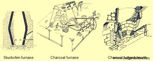
그림 3 Stuckofen 용광로 및 목탄 용광로
숯 고로의 진화
유럽대륙에서 개발된 목탄 BF(그림 3)는 곧 제철 기술의 차세대 진화가 일어난 영국으로 퍼졌습니다. 1565년 영국 몬머스셔(Monmouthshire)에 건설된 BF는 주요 제철 중심지가 된 딘(Dean) 숲에 건설된 최초의 용광로였습니다. 이 BF는 높이 4.6m, bosh에서 1.8m였으며, 두 개의 잘린 원뿔이 만나는 노 내부에서 가장 넓은 지점입니다. 1615년까지 용광로당 하루 평균 약 2톤의 BF가 300개 있었습니다. 성장 속도가 너무 빨라서 숯 생산을 위한 토지의 전체 삼림 벌채가 발생했습니다. 1600년대에 남아 있는 숲을 보호하기 위해 법적 제한이 있었고 많은 BF가 폐쇄되었습니다.
북미에 건설된 최초의 BF는 1622년 버지니아 주 폴링 크릭에 있었습니다. 이 용광로는 모든 공장 노동자가 사망하고 제철소가 아메리카 원주민에 의해 파괴되었기 때문에 가동되지 않았습니다. 북미에서 처음으로 성공한 숯 BF는 1645년부터 매사추세츠 주 소거스에서 시작되었습니다. 이 BF는 높이가 6.4m이고 외벽이 위로 올라갈 때 안쪽으로 기울어지고 바닥이 7.9m 정사각형인 더미를 가지고 있습니다. 용광로는 화강암과 기타 현지 돌을 점토 모르타르로 접착하여 만들었습니다. 그것은 큰 벨로우즈 휠을 구동하는 물이 특히 취약하게 만드는 습기로부터 보호하기 위해 지하 배수 시스템이 절단된 평평한 땅에 놓였습니다. BF는 내부가 대략 달걀 모양의 스택을 가지고 있었고 bosh의 상단으로 알려진 최대 직경은 1.8m였습니다. 아래쪽으로 기울어진 bosh는 광석, 플럭스 및 목탄의 충전을 지원했습니다. 난로라고 불리는 사각형 도가니는 bosh의 바닥 아래에 있었고 그것은 사암으로 라이닝되었습니다(그림 3). 내부 라이닝과 외부 석조물 사이에 모래, 점토 및 잔해가 있는 내부 벽이 있었는데 가열 및 냉각 주기 동안 팽창 및 수축을 위한 쿠션 역할을 했습니다. 두 개의 외벽에는 크고 깊은 아치가 있었다. 더 작은 아치를 통해 2개의 5.5m 벨로우즈와 2개의 송풍구의 기수를 통과하여 BF에 폭발을 전달했습니다. 더 큰 아치 아래에는 난로와 주조 바닥의 작업 영역이 있었습니다. 도가니 또는 난로는 액체 철의 저장소 역할을했습니다. 난로는 바닥에서 460mm 정사각형이었지만 1.1m의 전체 높이에 도달함에 따라 530mm로 확장되었습니다. 포로(for-hearth)라고 하는 아래쪽 부분의 돌출부는 두 개의 벽과 포레스트 또는 댐으로 구성되었습니다. 댐 위에서 뒤로 물러난 곳은 'tymp'라고 하는 돌로 된 외벽이 있었는데, 아래쪽 가장자리가 댐의 위쪽보다 아래로 내려왔습니다. 작업자는 tymp와 댐 사이의 구멍을 통해 주형 주조용 인두를 흘려보내고 링거(ringer)라고 하는 쇠 막대로 벽에 붙거나 송풍구 주변에 쌓인 슬래그를 긁어냅니다. 이러한 작업의 마모를 방지하기 위해 tymp와 댐은 모두 철판으로 덮였습니다. 슬래그 제거는 콘크리트 노치(cinder notch)라고 불리는 위치에서 댐 석재 위로 액체 재료를 긁어서 수행되었습니다. 그러나 철을 두드리기 위해서는 난로 측벽 중 하나와 댐의 한쪽 끝 사이에 있는 탭 구멍이라고 하는 좁은 공간에 삽입된 점토 플러그를 뚫어야 했습니다.
이 복잡한 석조 작업 외에도 BF의 설치에는 목재 및 가죽 작업이 포함되었습니다. BF 정상과 인접한 절벽 사이에는 차징 브리지(Charging Bridge)라고 불리는 무거운 목재 구조물이 있었습니다. 원료는 절벽 위의 비축된 수레에서 차징 다리를 건너 BF 정상까지 가져왔습니다. BF 상단의 3면에는 연기, 스파크 및 때때로 화염을 방출하는 충전 구멍에 원료를 충전하는 작업자를 위한 안전한 피난처를 제공하기 위해 설정된 목재 윈드 스크린이 있습니다. 지면에 있는 BF 스택은 주조 하우스라고 하는 목조 구조로 양면이 감싸져 있습니다. 이 구조는 트렌치 및 주형 주조 영역과 벨로우즈에 대한 덮개를 제공했습니다. 2개의 벨로우즈는 오버슈트 수차에 연결된 캠 샤프트에 의해 왕복 방식으로 구동되었습니다. 벨로우즈는 메인 샤프트의 캠에 의해 수축되었고 돌로 채워진 나무 상자로 구성된 균형추에 의해 팽창되었으며, 이를 수용하기 위해 절단된 구멍을 통해 주조 하우스 지붕 너머로 확장된 이동 빔에 장착되었습니다. BF는 생산된 철 1톤당 철광석 3톤, 플럭스 스톤 2톤, 목탄 2.6톤을 소비했습니다. 탭 구멍은 하루에 두 번 열렸고 각 주조 동안 약 450kg의 액체 철이 제거되었습니다. 액체 철은 단일 트렌치로 끌어오거나 모래 주형에 넣어 냄비, 프라이팬, 스토브 플레이트 등과 같은 국내 제품을 생산했습니다.
위에서 설명한 목탄 제철은 1700년대로 이어지는 100년 동안 약간만 바뀌었습니다. BF 스택의 크기가 증가하고 블로잉 장비가 개선되었습니다. 1700년대의 전형적인 목탄 BF는 높이가 9.1m, 보쉬 직경이 2.4m로 증가했습니다. BF 크기의 증가는 더 높은 폭발 압력을 초래하는 바람 전달 장비의 개선을 통해서만 가능했습니다. 블라스트 시스템의 첫 번째 개선은 사각형 또는 원형이고 외부 강철 고리와 함께 고정된 나무 통과 유사한 나무 송풍 욕조의 발명이었습니다. 물레방아의 편심 크랭크에는 왕복 피스톤 로드와 양쪽에 블로잉 욕조가 있었습니다. 욕조 내부의 피스톤은 가죽으로 끼워져 밀봉을 형성했습니다. 하나의 피스톤이 한 통의 공기를 압축하기 위해 상승할 때 다른 피스톤은 다른 통에서 하강했습니다. 각 통의 상단에는 항상 압력을 받고 있는 공통 혼합 상자에 연결된 출구 파이프가 있었습니다. 혼합 상자는 압축 공기를 노 송풍구로 이어지는 공기 덕트 또는 블라스트 메인에 공급했습니다. 일반적인 송풍조는 직경 1.8m, 높이 1.8m로 0.14kg/sq cm의 발파 압력을 생성했습니다. 나무 송풍 욕조의 개념은 1760년 영국의 John Smeton에 의해 한 단계 더 발전했습니다. 그는 나무 통을 처음에는 물레방아로, 그 다음에는 1769년에 증기 기관으로 움직이는 주철 통으로 바꾸었습니다. 증기 구동식 송풍 엔진을 사용하는 최초의 BF는 1769년 스코틀랜드에서 건설되었습니다. 증기 구동식 송풍 엔진의 발명으로 인해 더 높은 폭발 압력이 발생하여 광물 연료(코크스 및 석탄)를 더 사용할 수 있게 되었습니다. 1700년대의 이러한 개선으로 인해 BF 생산량이 1600년대 BF의 1톤/일에서 1700년대 후반까지 3~5톤/일로 증가했습니다. 이것은 광물 연료의 사용과 함께 유럽에서 목탄 용광로의 수를 급격히 감소시키는 원인이 되었지만, 북아메리카에서 목탄 철 용량은 인구가 목재가 풍부한 서쪽으로 이동함에 따라 증가했습니다.
1800년대에 목탄 철 생산량은 정점을 찍은 후 감소했습니다. 1800년대 중반, 원생림이 울창한 펜실베니아와 미시간 어퍼 반도에서 고품질의 철광석이 발견되었습니다. 이 지역에 건설된 숯 BF는 가장 크고 시설이 잘 갖추어져 있습니다. 이 BF는 스택 높이가 13.7m이고 보쉬 직경이 2.9m입니다. 송풍구의 수를 2개에서 3개로 늘렸는데 화로의 삼면에 각각 하나씩, 네 번째 면에 꼭지 구멍을 두었다. 송풍 장비는 일반적으로 직경이 최대 1270mm이고 스트로크가 1.5m인 수평 송풍 실린더였습니다. 승강기 유형 플랫폼 호이스트는 장입 브리지를 대체했으며 모든 철광석과 플럭스는 표준 장입의 일부로 계량되었습니다. 숯은 여전히 큰 수레의 부피만큼 충전되었습니다. 철 셸 플레이트는 석조 석재 더미를 천천히 대체했으며 자연석 안감은 알루미나 벽돌로 업그레이드되었습니다.
이러한 숯로에 설치된 주요 기술 개선 사항 중 하나는 장입 장비였습니다. 원래 원료는 터널 헤드를 통해 입이 열린 스택에 버려졌습니다. BF 운영자는 개방형 상부 용광로에 두 가지 단점이 있음을 깨달았습니다. 첫 번째는 굴뚝을 떠나는 가연성 가스를 화재 보일러로 포집할 수 없었고 두 번째는 원자재 분배로 인해 용광로 작동이 비효율적이었습니다. 1832년 독일에서 가스를 포집하기 위한 첫 번째 노력은 외바퀴 손수레에서 원료를 버릴 때만 열리는 장입구 위에 힌지 뚜껑을 설치하는 결과를 낳았습니다(그림 4). 또한 상부 스택에 위치한 용광로 측면에 개구부가 배치되었습니다. 이 구멍에는 보조 장비에서 태울 수 있도록 BF 가스를 지면으로 운반하는 다운 코머로 알려진 파이프가 장착되어 있습니다.
원자재 장입으로 인한 BF의 비효율성 문제는 여러 단계를 거쳐 발전된 보다 복잡한 솔루션이 필요했습니다. 높은 연료율로 설명되는 이 비효율의 원인은 BF 중앙의 장입구를 통해 버려지는 미세 물질이 더미 중앙에 남아 있는 반면 굵은 입자는 노 벽으로 굴러 내려오기 때문입니다. 이것은 BF 주변에서 더 높은 투과성을 가져왔고 따라서 대부분의 가스와 열이 벽으로 이동했습니다. 이것은 BF 중심의 재료가 용융 준비가 되지 않은 보쉬 영역에 도달하고 동시에 벽에서 과도한 가스 흐름이 라이닝 마모를 강화하기 때문에 BF 작업에 해로웠습니다. 이러한 부담분배 문제를 해결하기 위한 첫 번째 시도는 '컵앤콘' 충전장치의 도입이었다(그림 4). 그것은 장입 구멍을 공급하는 용광로 상단에 고정된 역 원추형 주철 깔때기로 구성됩니다. 이 원뿔은 목 직경의 약 50%였습니다. 원뿔 안에는 주철 컵이 있었는데, 이 컵은 평형추 반대편의 지주 빔에 매달려 있었습니다. 컵은 카운터웨이트에 연결된 윈치를 사용하여 수동으로 들어 올렸습니다. 이 장치는 가스를 포착하는 데 성공했지만 여전히 많은 양의 거친 물질이 벽에 굴러 떨어졌습니다. 컵 및 콘 장비에 대한 다음 수정은 용광로 내부에 주철로 잘린 원뿔을 걸어두는 것이었습니다(그림 4). 그 결과 원자재의 피크가 벽에 더 가깝게 이동하여 굵은 입자가 이제 노의 중심으로 굴러갈 수 있어 중앙 투과성과 가스 흐름이 향상되었습니다.
컵과 콘을 완전히 제거한 장입의 다음 진화 단계는 용광로로 아래쪽으로 열리는 거꾸로 된 원뿔을 매달아 두는 것이었습니다(그림 4). 최초의 벨형 BF탑입니다. 이 벨은 주변의 가스 흐름을 줄이고 중앙의 가스 흐름을 증가시키는 벽의 피크를 밀어내는 데 성공했지만 벨이 내려갈 때마다 BF 가스가 스택에서 빠져나갔습니다. 이에 대한 해결책은 충전 구멍을 위한 벨과 뚜껑을 갖는 것이었습니다. 자재가 수레에서 버려졌을 때 뚜껑은 열려 있었지만 벨은 닫혀 있었고 가스는 BF에 유지되었습니다. 그런 다음 뚜껑을 닫고 벨을 버려 BF에 가스를 유지하면서 동시에 적절한 부담 분배를 산출했습니다. 이러한 개선의 결과 BF 내부의 물리적 및 화학적 반응 효율이 향상되어 연료 요구량이 감소하고 생산성이 향상되었으며 내화 라이닝 마모가 감소했습니다.
<강한> 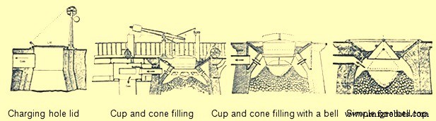
그림 4 BF 탑 장비의 진화
많은 설계 개선으로 인해 BF 생산량이 증가함에 따라 액체 제품(철 및 슬래그)의 제거가 문제가 되었습니다. BF 목탄 생산량은 하루 1톤에서 25톤으로 증가했습니다. 이 더 높은 톤수는 탭 구멍 앞의 단일 트렌치를 통해 하루에 두 번 주조로 처리할 수 없었습니다. 캐스트 하우스 건물의 크기는 약 12m 너비와 21m 길이로 증가했습니다. 주조소에는 철 주조 및 슬래그 제거를 위한 별도의 구역이 있었습니다. 철 제거를 위한 측면은 용광로 전면에서 모래로 채워진 주물 집 바닥으로 아래쪽으로 경사진 홈통이라고 하는 큰 도랑으로 구성되었습니다. 그런 다음 두 개의 러너 시스템으로 유출되었습니다. 각 시스템의 메인 러너는 캐스트 하우스의 길이와 평행하게 달렸습니다. 이 러너가 내리막길을 오르면서 일정한 간격으로 일련의 댐이 만들어졌습니다. 각 댐 앞에 직각으로 '암퇘지'라는 작은 주자가 모래에 형성되었습니다. 그런 다음이 암퇘지에서 '돼지'라고 불리는 수많은 구멍이있었습니다. 이 이름은 이 시스템이 어미에게 젖을 먹이는 새끼 돼지의 줄처럼 보이기 때문에 적용되었습니다(그림 5). 캐스트 하우스 바닥의 축축한 모래에 D 자 모양의 나무 거푸집을 밀어 낳은 암퇘지와 돼지가 여러 줄로 평행을 이뤘습니다. 주조하는 동안 각 암퇘지와 그 돼지는 액체 철로 채워져 주 러너의 모래 댐이 막대로 녹아웃되고 용융 금속이 다음 암퇘지와 돼지 침대로 내리막길로 떨어졌습니다. BF가 더 자주 캐스팅되도록 하는 두 가지 완전한 시스템이 있었습니다. 한 면은 액체 철로 채워져 있고, 다른 면은 돼지를 제거하고 침대를 개조했습니다.
<강한> 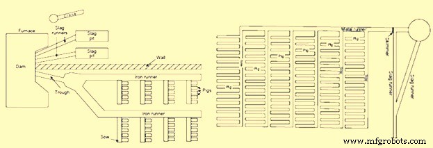
캐스트 하우스의 그림 5 돼지 침대
캐스트 하우스의 다른 쪽은 슬래그 제거에 사용되었습니다. 슬래그는 슬래그 러너를 따라 슬래그 구덩이로 끊임없이 댐 전면을 흐르고 있었습니다. BF 전면에 있는 슬래그 댐은 두 개의 반으로 나뉘었고 각 반은 별도의 슬래그 러너와 슬래그 피트에 공급되었습니다. 슬래그 구덩이는 바닥에 융기가 있는 모래의 큰 함몰부였습니다. 이 융기부는 응고된 슬래그를 제거할 때 파단점으로 작용하였다. 일부 캐스트 하우스에서는 지브 형 목조 크레인을 사용하여 큰 슬래그 조각을 들어 올렸습니다. 주조소 작업자는 슬래그 층이 너무 두꺼워지는 것을 발견하면 일반적으로 액체 슬래그의 중앙에 막대를 배치합니다. 그런 다음 막대 주위에서 슬래그가 차가워지면 밧줄이나 사슬이 막대 주위에 감쌀 수 있고 큰 슬래그 조각이 크레인으로 들어 올려집니다. 슬래그 제거를 위해 두 개의 완전한 슬래그 시스템도 있어서 하나는 사용하는 동안 다른 하나는 청소하고 준비할 수 있었습니다.
'주물'이라는 단어의 어원은 쇠를 화로에서 '끄집어낸다'는 인식에서 나온 것으로 이해된다. 주조 작업은 두 부분으로 구성됩니다. 첫 번째 부분에서 액체 슬래그가 BF에서 형성되는 동안 tymp와 댐 사이에서 슬래그 러너와 피트로 흐를 수 있을 만큼 충분히 높은 수준에 도달할 때까지 액체 철 위에 떠 있었습니다. 주조의 두 번째 부분은 용광로의 난로에서 액체 철 제거를 제거하는 것이었습니다. 이것은 폭발을 차단한 다음 큰 망치로 탭 구멍에 뾰족한 막대를 밀어 넣는 것으로 시작되었습니다. 액체 철은 여물통을 따라 각각의 연속적인 암퇘지와 그 돼지에게 흘러 들어갔습니다. 액체 철의 흐름이 멈췄을 때 탭 구멍은 모래와 내화 점토 또는 모래와 석탄의 축축한 혼합물로 수동으로 막혔습니다. 그런 다음 폭발은 용광로로 되돌아갔습니다.
주조 후 주조소 작업자는 돼지 침대에서 응고된 철을 제거했습니다. 돼지를 다룰 수 있을 만큼 식으면 파견을 위해 보냈습니다. 이 사이클은 하루에 6번 반복되었으며 각 주조에서 4-6톤이 생산되었습니다. 생산된 선철은 여러 등급으로 분류되었습니다. 목탄 철은 황 값이 낮아서 1800년대의 확장 철도를 지원하는 데 필요한 레일과 철도 차량 바퀴를 생산하는 데 사용된 질긴 회주철이 되었습니다.
목탄 BF는 생산 비용이 더 이상 광물 기반 제철 관행에서 오는 경쟁을 충족할 수 없었기 때문에 1800년대 후반에 중단되었습니다.
광물 연료를 기반으로 한 제철
숯 제철을 유지하는 데 필요한 원시림의 고갈로 인해 대체 연료 공급원을 찾는 것이 필요하게 되었습니다. 이 대체 연료는 역청탄, 무연탄, 코크스 및 이탄의 형태로 제공되었습니다. 코크스와 무연탄 제철의 발달은 1700년대와 1800년대에 숯 생산과 병행하여 공존했습니다. 역청탄과 이탄의 사용은 제한적이었고 결코 주요 제철 연료가 되지 못했습니다. 제철을 위한 광물 연료의 사용은 숯 생산으로 인한 삼림 벌채가 처음 발생한 영국에서 시작되었습니다.
1708년에 Abraham Darby는 Shropshire에서 작은 목탄 BF를 임대하여 1709년까지 코크스를 생산하고 있었습니다. 1709년부터 1718년까지 코크스는 이 용광로에서 점점 더 많은 비율로 목탄과 혼합되었으며 1718년에는 BF가 100% 코크스를 사용했습니다. 1750년까지 정기적으로 콜라를 사용하는 세 명의 BF는 Darby 가족에 속했습니다. 코크스의 사용은 1750년에서 1771년 사이에 퍼졌고 총 27개의 BF가 철 생산을 위해 코크스를 사용했습니다. The use of coke increased the production of iron since it was stronger than charcoal. It could support the weight of more raw materials and thus the size of BF could be increased. Coke also improved permeability in the BF, allowing a larger volume of wind to pass through the furnace. This larger volume of compressed air was provided by the steam engine and blowing cylinders.
The use of coke in continental Europe spread slowly. Coke was used in Le Creussot, France in 1785, Gewitz, Silesia in 1796, Seraing, Belgium in 1826, Mulheim, Germany in 1849, Donete, Russia in 1871 and Bilbao, Spain in 1880. In North America, the first use of 100 % coke as the fuel was in 1835 at Huntington, Pennsylvania. However, since 1797, coke was mixed with other fuels in BFs of US.
The efficient use of coke and anthracite in producing iron was accelerated not only by the use of steam-driven blowing equipment but also by the invention of preheating of the air being blown in the BF. In the beginning of the 19th century, it was believed that use of cold blast improved both the quantity and quality of pig iron since it was observed that the production of the BFs was more in winter months and it was erroneously concluded that the lower blast temperature was the reason. But the BF performance improved during the winter months due to the fact that the air was having lower humidity so that more combustion of fuel was supported by a given volume of air blown into the furnace.
In 1828, James Neilson patented his invention of supplying preheated air blast to the tuyeres. The heating equipment was a simple wrought iron box having dimensions 1.2 m x 0.9 m x 0.6 m. This wrought iron box was externally heated. The maximum blast temperature which could be attained with this box was 93 deg C and one box was needed for each tuyere. In 1832, Neilson improved his invention by constructing a larger oven by joined flanges, formed a continuous length of 30 m and provided a heating surface of 22.3 sq m. This oven, which was fired with solid fuel, produced a hot blast temperature of 140 deg C. Since this invention, continuous modification and improvement in the hot blast ovens were made and by 1831, Dixon developed a taller oven with U-shaped pipes that supplied hot blast at 315 deg C. By 1840, about 55 % of pig iron at Great Britain was produced with hot blast.
With the increase in the hot blast temperature, there was decrease in the quantity of fuel needed and increase in the BF production. However the hot blast equipment needed a lot of maintenance. The cast iron pipes supported within a brick oven had different expansion characteristics, which resulted in several cracked pipes. Another issue was that the delivery equipment used for the cold blast, which consisted of solid tuyeres and flexible leather joints between pipes, could not withstand the high temperatures. Another issue with the original hot blast systems was the increased cost of solid fuel to heat the ovens. These issues helped further improvements in hot blast equipment. First, solid fuel used for heating was replaced with BF gas. Initially primitive heat exchanger type hot blast equipment was built on top of the BF and simply used the waste heat to preheat the cold blast running through the cast iron pipes. Then the BF gas from the furnace top was conveyed to the hot blast oven where it was burned to generate heat. This type of hot blast oven became quite complex with numerous rows of vertical pipes. The issue of cracking of the cast iron pipes was tackled by eliminating the pipes and using refractory. For using this method, 2 to 4 stoves were installed for each BF. As one stove was being heated by the burning the BF gas, another was being drained of its heat by heating of the cold blast. In 1854, the Cambria Iron Works was the first plant in the US to use regenerative stoves. The stoves were constructed of iron shells, internally lined with refractory and containing refractories with multiple passages for the blast. A typical stove of this design had 186 to 232 sq m of heating surface. These stoves were representative of those produced by Cowper and Whitwell in 1857. The Whitwell stoves erected in 1875 were 6.7 m in diameter, 9.1 m high and had a total heat surface of 8546 sq m. These were the first stoves to use hexagonal refractory checkers, cast iron checker supports, and a semi elliptical combustion chamber to improve distribution of gas through the checkers. These stoves could supply hot blast to the BF with temperatures of 454 deg C to 566 deg C. This stove design has remained basically the same till date with minor modifications in refractory type, checker shape and stove size.
The other improvement in equipment required by the use of hot blast was the design of the tuyeres and the tuyere stock. The solid cast iron or cast copper tuyeres used on cold blast furnaces were replaced by water cooled tuyeres which were hollow, conical shaped castings which had water circulating through their interior. The pipes from the blowing engines to the tuyeres, which were jointed with leather on cold blast furnaces, were redesigned with metal-to-metal seats. As hot blast temperatures increased the inside of these blast mains and tuyere stocks were lined with refractory, which required an overall increase in size.
The use of hot blast was applied to both coke and anthracite furnaces. As blast pressure increased with new blowing engines, it was found that anthracite could be charged with charcoal to improve the BF productivity. During 1986 the first attempt was made to use anthracite in a cold blast furnace in eastern France. This attempt failed since the ignited anthracite broke up into small pieces and blocked the blast from entering the BF. The evolution of coke iron making and anthracite iron making paralleled each other in the US during the 1800s. In 1826, a small BF was erected in Pennsylvania to operate exclusively on anthracite coal. This practice was unsuccessful both there as well as at other places in the US. During 1833, Dr. Frederick Geissenhainer successfully used hot blast in experiments to smelt iron with anthracite coal. In 1836 the Valley furnace in Pennsylvania used 100 % anthracite and in 1837, George Crane produced 36 tons of anthracite iron per week from one of his BFs at South Wales. David Thomas was the most successful iron maker in using the anthracite in the BF. In 1838 he came to the US and built the Catasauqua BF in 1840 (Fig 6). The furnace was 10.7 m square at the base with 3.6 m bosh and a height of 13.7 m. The hot blast stoves, fired with coal, were capable of heating the blast to 315 deg C. Since this BF successfully produced 50 tons of good foundry iron per week, the furnace was used as a model for the construction of blast furnaces built for using anthracite as a fuel. By 1856 there were 121 anthracite furnaces in operation in the US.
Other fuels were also tried for iron making in the BF. These were peat and bituminous coal. Peat BFs were similar to charcoal furnaces and typically were no higher than 6.7 m. Because the peat was physically weak, the use of these furnaces was located near to the peat deposits and they never played a major role in iron making evolution. Bituminous coal had been used to supplement charcoal prior to the introduction of hot blast. In the 1830s, splint coal was used in Scottish hot blast furnaces. In 1856, there were 6 BFs in Pennsylvania and 13 BFs in Ohio using bituminous coal. The bituminous coal era of iron making was essentially finished by 1895. This method of iron making never became a major force since the coal broke up into small pieces as the BFs were made larger and used higher blast pressure. With coke being the strongest and most available fuel, the evolution of 100 % coke furnaces continued. However there were initial setbacks probably due to low strength coke. By the 1840s coke quality had improved through the use of beehive ovens. In 1867, the ‘Monster’ blast furnace was built at Norton, England. This coke furnace was 25.9 m high, 7.6 m across the bosh and had a working volume of 735 cum. An example of a large coke furnace in the US in 1884 was the Etna furnace located near Pittsburgh. This furnace was 21.3 m high, 6.1 m in diameter at the bosh, 3.4 m in diameter at the hearth and had seven 7 inch (178 mm) tuyeres, three Whitwell stoves and three blowing cylinders that were 2.1 m in diameter. This BF produced 115 tons/day in 1881, 161 tons/day in 1882 and 182 tons/day in 1883. The coke furnace design at this time was very similar to the anthracite furnaces of the same era (Fig 6).
Further evolution of coke blast furnace
The evolution of BFs using 100 % coke continued with major improvements being made between 1872 and 1913. Several technological improvements were made which were centered on the hard-driving BF practice of using more powerful blowing engines, higher blast temperatures, bigger furnaces, better charging equipment, improved raw material preparation and production of clean BF gas.
Blowing equipment design and capacity was a major step to higher production in the hard-driving BFs. Blowing cylinders were replaced with large steam reciprocating blowing engines capable of providing a greater volume of blast air at a significantly higher blast pressure. These blowing engines were of the walking beam, steam condensing type. The steam cylinder’s piston rod was connected to a gallows beam and then by a crank to a heavy, large diameter flywheel. The blowing cylinder’s piston rod was connected to the other end of the gallows beam and each stroke of the steam cylinder provided a corresponding stroke of the blowing cylinder. Cold blast pipes were fitted to each end of the vertically positioned blowing cylinder so that air was compressed on both directions of the stroke. The flywheel provided momentum for the return stroke of the steam cylinder. The air that was compressed in this manner left the cold blast pipes and entered the cold blast main which connected to the hot blast stoves. Prior to this type of blowing engine the normal blast volume was 210 cum/min at a blast pressure of 0.28 kg/sq cm. This blowing engine could produce 456 cum/min at a blast pressure of 0.64 kg/sq cm. Then in 1910, the final major step in blowing engine improvement was implemented in the form of a turbo-blower. The first turbo-blower was installed for the BF of the Empire Steel Co. in New Jersey and was capable of delivering 636 cum/min of air blast. This turbo- blower was the direct ancestor of the modern turbo-blower which can deliver up to 7500 cum/min of blast volume at 4.00 kg/sq cm of blast pressure.
Another major improvement in high productivity BFs was to increase the charging capacity. In the 1870s the BFs were equipped with water driven elevators. In 1883, the first skip hoists were installed. Skips have become larger and faster into the 20th century and existed as both buckets and cars mounted on wheels. In the early 1960s some skip charging systems were replaced with large conveyor belts.
The improvements in furnace charging capacity also included automatic coke charging systems, scale cars in the stock house, two bell tops and the rotating distributor (Fig 6). Automatic stock line measurement was invented in 1901 by David Baker. In 1903, JE Johnson also began to measure top gas temperature and its analysis.
By 1850 as the furnace size increased, the furnace top could be closed. A single bell and hopper arrangement could be used for charging the furnace that kept the top of the furnace closed and sealed. The single bell and hopper system permitted large quantity of gas to escape every time the bell was opened. Soon a second bell and hopper was added above the first so that a gas tight space could be provided between the two bells to prevent the blast furnace gas escaping when the small bell was opened. The upper bell and hopper did not have to be as large as the lower one because several charges could be deposited through it on the lower bell and the upper bell could be closed before the lower bell was opened for dumping the charges in the furnace
Attempts to improve burden distribution occurred in the early 1990s with the McKee rotating top. After each skip of material was charged onto the small bell, the small bell hopper was rotated 60 deg, 180 deg, 240 deg, 300 deg, or 0 deg. This prevented a peak of raw material directly below the skip bridge which had resulted in uneven gas distribution and uneven lining wear. The next attempt to improve burden distribution was done in Germany in the late 1960s. This was accomplished by installing movable panels at the throat of the BF that could be set at different angles for ore or coke. This movable armour has been installed on large numbers of BFs.
The two bell system continued to be the only charging system for the blast furnaces around the world till S.A. Paul Wurth in Luxembourg, developed bell less top (BLT) charging system and the first successful industrial application of BLT charging system was in 1972. This equipment used air tight material hoppers that fed a rotating raw material delivery chute which could be set at numerous angles during the hopper discharge into the furnace. The result was the almost unlimited placement of each material anywhere on the burden surface which allowed the operator to achieve maximum fuel efficiency.
The BLT charging system took over from two bell charging system since it provided a number of advantages to BF operators. During 2003, Siemens VAI introduced Gimbal concept of charging.
Another attempt in the direction of the continuous improvement of the BFs for increasing the production was towards improvements in the cleaning of BF gas. As blast volume and pressure increased at the tuyeres, the velocity and volume of gas leaving the BF top also increased. More flue dust was then carried by this waste gas and if it was not removed, it began to plug up stove checkers which subsequently restricted blast volumes to the furnace. The first step in gas cleaning was the introduction of the dust catcher in the 1880s. With the introduction of the soft iron ores in 1892, the dry-type dust catcher was not sufficient. In 1909, Ambrose N. Diehl introduced a wet gas cleaning system. It consisted of a series of nine high-pressure spray towers and a set of four rotary washers. From 1914 to 1924, several types of tower washers equipped with multiple banks of sprays and baffles were tried at various furnaces. Gas disintegrators which contained high speed rotary drums were also tested in 1907. In 1929 electrostatic precipitators were used successfully at South Works of U.S. Steel. Today, combinations of tower-type gas washers, Venturi scrubbers and mist eliminators are the most common types of gas cleaning equipment.
The newest wet gas cleaning equipment is an annular gap scrubber which cleans the gas as well as controls top pressure. The final result of all these gas cleaning improvements was a decrease in stove checker brick hole diameter with an increase in stove size because plugging with dirt had been virtually eliminated. The resulting increase in stove heating surfaces has ultimately allowed modern stoves to deliver up to 1270 deg C hot blast temperature. The associated top pressure control allowed by modern gas cleaning equipment has resulted in furnace top pressures up to 2.3 kg/sq cm. This higher top pressure in turn increases the density of gases, decreases gas velocity and increases gas retention time in the furnace, yielding better gas-solid reactions, improved reducing gas utilization and lower fuel rates.
Recently, on the newly built and reconstructed BFs, particularly in China, dry cleaning of BF gas by bag filters has found the wide application. Dry cleaning of gas has several advantages over wet gas cleaning using scrubbers and Venturi tubes.
The quest for higher production rates in the late 1870s and onwards forced changes in the size of the furnace size and its configurations. In the 1870s, the furnaces were 22.9 m high. In 1880, the BF size increased to 24.7 m high, 6.1 m bosh diameter and 3.4 m hearth diameter. It produced 120 tons/day with a 1574 kg/ton coke rate. Just ten years later, in 1890, BF was constructed with a stack 28.0 m high and with 6.7 m bosh. It produced 325 tons/day. Then in another 10 years, in 1901, BF was started with similar stack and bosh dimensions as earlier furnace but the hearth diameter was increased to 4.4 m. This furnace produced 463 tons/day at 1113 kg/ton coke rate. The other subtle change with these size increases was the lowering of the bosh/stack bend line and the steepening of the bosh angle. This change was detrimental as the furnaces saw poor burden descent and slipping with these bosh angles. To eliminate these problems, the hearth diameter of these size furnaces was increased up to 6.7 m in 1927. This bigger hearth furnace produced 880 tons/day at a coke rate of 922 kg/ton. The first 1000 ton/day furnace was commissioned in 1929. This furnace was equipped with a hearth diameter of 7.6 m. In 1955, Great Lakes’ A furnace was the largest in the world with a 9.2 m hearth and 24 tuyeres. The next leap in blast furnace size increase occurred during the 1960s as Japan rebuilt their outdated steel plants. Today, furnaces with 15 m hearth diameter, 40 tuyeres and four to five tap holes, are common in Europe and Asia.
Along with the larger furnaces, higher blast temperatures and increasing driving rates, came the need for better BF refractory lining and cooling systems. In the 1880s a high duty fireclay brick with around 40 % alumina and 46 % silica was typical. However, C refractories were used in German BFs since 1886.
While refractory technology was relatively unknown at this time, methods to cool the lining seemed to be the answer to the wear problem. Beginning about 1880, there were simultaneous developments in efforts to maintain furnace linings by means of pipe coils around the bosh or by cooling plates embedded in the brick. One of the first uses of a bronze bosh plate is believed to be an installation made by Julian Kennedy at one of about 1890. An early reference to the use of water-cooled hearth jackets is on the furnace was in 1882. At this time, cooling of the hearth sidewalls and bosh was the concern and stack cooling was not felt to be necessary.
Fritz W Lurman, a well-known blast furnace man of the time opined in 1892 that ‘irrespective of the use of so called refractory materials, the best means of maintaining the walls of the blast furnace is with cooling water’. Coolers with water circulating in them are installed between the shell of the blast furnace and the refractory lining in the upper part of the furnace to protect these components from heat radiation. In addition to having its own coolers, the part of the shell adjacent to the hearth and the bottom of the furnace is also cooled in some furnaces on the outside by water sprays.
Function of blast furnace cooling system is to cool the furnace shell and prevent from the overheating and subsequent burn through. Cooling system removes the excess heat generated in the blast furnace which is otherwise loaded on the shell. Cooling system thus prevent the increase of the shell and lining temperature. Various methods exist for cooling of the shell for the blast furnace. In earlier times, cooling boxes of different size, number and design were used for transferring heat of the furnace to a cooling medium in conjunction with external cooling (spray cooling, double shell). Blast furnaces with cast iron cooling staves are operating since mid-1900s. Cast iron stave cooling was originally a Soviet discovery from where it travelled initially to India and Japan. By 1970s, cast iron cooling staves have attained world-wide acceptance. Since the introduction of these cast iron stave coolers, the development work of blast furnace cooling got accelerated and today a wide variety of coolers are available for the internal cooling of the furnace shell to suit extreme condition of stress in a modern large high performance blast furnace.
The higher charging rates were also wearing out the throat of the furnace faster. In 1872, iron or steel armour was built into the brickwork of the furnace throat at a furnace. Since that time, various types of armour have been used in the stock line area.
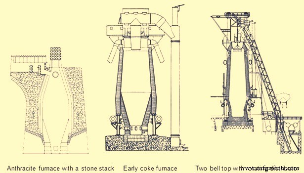
Fig 6 Early blast furnaces
The first important developments in brick making technology did not occur until the 1900s. In 1917, the first machine-made brick was introduced with its resulting increase in density and strength. In 1935, vacuum pressed bricks further improved brick quality. In 1939, super-duty alumina brick containing up to 60 % alumina was first available. In the 1930s, carbon blocks were used in German furnace hearths. Today many varieties of alumina, carbon, and silicon carbide refractories are available for BF lining. The improvements in furnace cooling and lining have increased typical campaign lengths from two years in the 1880s to more than ten years in the 1990s. Today campaign life of BFs has further increased to 20 years.
Another area of the BF which was forced to change with increased production was the casting operation. The old style tymp and dam open front of the furnace was no longer adequate. In 1867, the Lurman front was patented to eliminate the tymp and dam. It consisted of a cast iron panel which was water cooled and had separate openings for iron removal (still known as a tap hole) and for slag removal (known as the slag or cinder notch). This design was changed by the 1880s by rotating the slag notch 90 deg from the tap hole. Both the tap hole panel and slag notch panel were water cooled. By separating these two liquid tapping points, more room was available to set up the furnace for the increasing number of casts required at higher production rates. The area in front of the tap hole was completely available for pig beds while the slag pits were moved around to the side of the furnace (Fig 5). During normal operation, the slag notch was opened with a bar as the liquid slag level approached the tuyeres. The slag was flushed into pits or special slag cars. When the slag notch blew wind out of the opening, it was closed with a manual stopper. By tapping the slag off between iron taps, a greater volume of the hearth was available for liquid iron which resulted in larger cast tonnages. The iron casting process in the 1880s did not change much from previous operations but pig beds were bigger and in 1909 a slag skimmer was installed to skim the floating slag off of the iron as it flowed down the trough.
In 1896, the installation of a pig casting machine invented by EA Uehling finally brought about the complete elimination of the pig bed in the cast house. Next the open-top brick lined ladles were introduced. These ladles carried about 10 tons to 100 tons of hot metal and required the furnace and cast house to be elevated above ground level so the ladles could be placed under the cast house floor. Though the pig beds have got eliminated but troughs and runners remained and spouts going into the ladles were added to the cast house. In 1915, there was first use of the torpedo type ladles. These railroad mounted ladles carried 90 tons but were increased to 150 tons by 1925. Today, the iron ladle design is similar but capacities up to 400 tons are available. Open-type ladles mounted on rail cars are still used today.
Prior to 1890, the tap hole was opened with a bar and sledge hammer. Then in 1890 the first pneumatic rock drill was used. The tap hole was manually stopped with wind off the furnace until 1914 when HA Berg developed the remote controlled mud gun which pushed a clay plug into the furnace with a wind on. In 1906, the first oxygen lancing was used to melt skulls in the tap hole. Modern BFs have evolved to include remote controlled tap hole drills, hydraulic mud guns, cast house slag granulation units and iron tilting spouts to feed an unlimited number of iron ladles. BFs may also have from one to four tap holes and two to six slag pits depending on their size. Removing the bottleneck in the cast house allowed the first 1000 ton/day operation in 1929 and led to 1990s production levels of 12,000 ton/day.
A parallel line of improvement activities which rapidly evolved starting in the late 1800s was iron ore preparation. Iron ore used in iron making consists of many geological forms such as red hematite, specular hematite, magnetite, limonite, fossil ores, bog ores and carbonates. The metallic iron content of these ores ranges from approximately 30 % in the bog ores to 72 % in some hematites. All iron ores are mixed with other compounds in the earth which are undesirable in the smelting process. Beginning in the 1700s, iron ore was roasted with charcoal in open pits or enclosed kilns. The object of roasting or calcining was to liberate all volatile constituents, such as water, carbonic acid or bituminous substances, and to soften and crack the ores, making them more permeable to reducing gases. In the 1800s, iron ore screening was introduced to more closely size the ore for improved gas permeability inside the furnace. At first, hand screening equipment was used but, by the 1870s, steam-driven ore washers consisted of one or two drums that were perforated with holes or slots for the fine material to exit with the wash water while the final sized and washed ore exited the inside of the drum into a wheelbarrow or stockpile.
As iron production increased, the purest iron ores were depleted in many areas so lower grade ores had to be mined. These ores had undesirable impurities and methods to concentrate these ores to higher iron percentages were required. In 1880, Thomas A. Edison obtained a patent for an electromagnetic separator. A demonstration plant was built in Michigan and produced 893 tons of magnetic concentrate in 1889.
Pilot plants to pelletize taconite concentrates were built in 1948. By 1956, two commercial-scale taconite mining and processing operations were producing pellets. The first straight grate pellet machine was made in 1956 and the first grate-kiln pellet machine was put into operation in 1960. Pelletizing technology spread throughout the world from the US. The newest development in pelletizing was the introduction of raw limestone, dolomite or olivine into the pellet to improve its metallurgical properties which, in turn, improved BF productivity and fuel rates.
Iron ore agglomeration also took a separate route from pelletizing earlier in the 1900s. Sintering process originated in the nonferrous industry as a batch process in the late 19th century. Up to the 1950s, most sinter had a basicity ratio of less than 1.0. However, over the next fifteen years, it was realized that a basic sinter with a basicity ratio of more than 1.0 brought a pre-calcined flux source into the BF which resulted in a fuel rate savings.
One of the final technological improvements in iron making over the last 100 years has been tuyere level injectants. The first recorded use of injectant was in 1871 when there was a chilled hearth on the Morgan charcoal furnace. Because blast could not enter the tuyeres due to chilled material, a hole was punched through the furnace wall above the salamander and a large tuyere was installed. Coal oil was then forced under pressure into the tuyere from a pipe running from the top of the furnace. Six days and seven barrels of oil later the salamander had been melted and the furnace was running smoothly. In the first decade of the 1900s early tests with oxygen injection were made in the small BF in Belgium. The first large scale oxygen enriched blast was used in 1951. The benefits of pure oxygen injection are increased BF production due to increased fuel burning capacity and an ability to use more hydrocarbon tuyere injectants. The evolution of hydrocarbon injectant occurred in the 1940s and 1950s. In 1944, William L. Pogue submitted a patent for the use of coal injection. Then in 1953, natural gas injection was implemented. In the early 1960s, injection of oil and tar through lances was developed at numerous steel companies after substantial coke savings were proven by testing in an experimental BF in 1959. By 1967, a large number of the BFs were using some form of fuel (mostly pulverized coal) injection. Today, many BFs use fuel injectants 40 % to 45 % of the fuel rate. The final tuyere injectant, which evolved concurrently with fuel injection, was moisture injection. Historically, hot blast temperatures were limited as excessively high temperature combustion zones resulted in poor burden descent. The injection of moisture consumed coke more rapidly than air alone and produced a gas that was both richer in carbon monoxide and hydrogen and was less dense. These factors improved the rate of heat transfer between gases and solids and the rate of reduction of the burden in the furnace stack, which resulted in a smooth running furnace.
The combination of moisture injection, fuel injection and oxygen injection permitted the increase of hot blast temperature and the use of all of these tuyere level variables further improved productivity and reduced fuel rates in modern BFs.
Evolution of BF iron making as a science
Historically, iron making was more an art than a science. Early iron producers learned their trade through years of training from the previous generation. Many improvements in iron making practice were based on instinct or pure luck. However, by the mid-nineteenth century, science was creeping into the developments in iron smelting.
Charles Schinz of Germany, one of the earliest researchers of chemical and physical phenomena occurring inside a BF, attempted to make quantitative mass and energy balances of BF operation but he was severely limited by the lack of accurate thermodynamic data. He conducted laboratory experiments to determine heat capacity and heats of formation and was apparently the first to determine the reducibility of iron ore. He defined different zones of the BF and the major chemical reactions taking place in each zone. The results of his work were published in 1868.
Several principles which are recognized today were postulated by Sir Lothian Bell, during the late 1800s. He published a book in 1872 which is recognized as the first text book on BF iron making. In 1884, he was seemingly the first to document the function of the different slag components and their effect on melting temperature. He also observed that BF slags are complex structures and there is a range of slag compositions which results in its good fluid properties and desulfurizing capability. His most important contribution was his understanding of chemical reactions. He recognized the importance of CO and CO2, and was the first to start defining equilibrium in the Fe-O-C system. Further, Bell discussed preheating and pre-reduction of iron ores and the importance of the furnace stack where these reactions occurred. He also made carbon, oxygen and nitrogen balances of the BF operations and showed that some of the charged carbon was consumed in the stack by CO2 in the ‘solution loss’ reaction.
A contemporary of Bell was ML Gruner, a professor of metallurgy in France, further expanded Bell’s methods of determining BF heat balances by comparing many different furnace operations. He also believed that the minimum fuel rate for BFs would be achieved when solution loss was eliminated.
JE Johnson, Jr. was the first American scientist to explore the BF process and published two books on BF design and operation in the early 1900s. He applied the first and second laws of thermodynamics to iron making and explained how fuel rate was impacted by blast temperature. He postulated that there was a critical furnace temperature above which a minimum amount of heat is required. This minimum amount of heat he called ‘hearth heat’. In his book, published in 1913, Johnson produced a diagram showing chemical reactions and isotherms in the BF. The application of the critical temperature and hearth heat concepts further convinced furnace operators that the BF process was rational and predictable.
During the period from 1920 to 1930, the flow of solids and gases in the BF was studied extensively by a group of workers named PH Royster, SP Kinney, CC Furnas, and TL Joseph. This group was interested in physical and chemical phenomena occurring in BFs and in order to understand these phenomena they felt it was necessary to sample and probe operating furnaces. Their work started with a small experimental BF and spread to commercial furnaces. The results of their studies showed that the flow of gases and solids was not uniform across any horizontal plane in the BF and that improving gas-solid contact in the stack of the furnace could significantly increase the efficiency of the iron making process. Furnas and Joseph continued this work and determined that raw material size and reducibility was critical in gas-solid reactions. This important work led to the understanding of burden distribution and the optimization of iron ore sizing as it impacts both reducibility and permeability.
In 1962, R. Stephenson explained the role of solution loss. Previously, it had been thought the production of CO by reacting with CO2 and carbon was a waste of fuel. Stephenson pointed out that iron oxide reduction is a combination of indirect reduction and direct reduction and that indirect reduction followed by solution loss is direct reduction. Using these considerations to determine carbon rates for all combinations of these two reduction routes as a function of solution loss, results can be plotted on the ‘carbon-direct reduction diagram’. In the 1960s and early 1970s, the best applications of these BF theories were put into practice in Japan. Currently, the Japanese improvements have spread in the form of large, highly automated BFs to other places.
The theory and practice of iron smelting technology have come a long way in the last 4000 years. The transition from sponge iron produced in forges to liquid iron produced in BFs in the 1300s was the first major step in advancing iron making technology. Then came the change from cold blast, charcoal furnaces to hot blast, coke furnaces in the mid-1800s which brought iron making into the modern era. The better understanding of iron making reactions and improved equipment evolved into the hard-driving furnace operation centered in the 1880s to 1900s. Finally, the revolution in scientific applications to iron smelting, the installation of more sophisticated equipment, and the advent of electronically controlled systems has accelerated BF iron making into the current state as demonstrated by the operation of around 12,000 tons/day BFs with fuel rates less than 460 kg/ton.
제조공정
제철을 위한 Matmor 공정 Matmor 공정은 현재 Environmental Clean Technologies Ltd(ECT)에서 개발 중인 제철 공정입니다. Matmor 공정 기술은 특허 기술입니다. 이 기술은 갈탄을 기반으로 하며 독특한 화학 및 용광로 설계로 인해 고급 철광석을 저렴한 대체 원료로 대체할 수 있습니다. 일반적으로 갈탄(갈탄이라고도 함)은 휘발성 물질과 수분 함량이 높기 때문에 야금 용도로 사용되지 않습니다. Environmental Clean Technologies Ltd는 공장, 장비 및 지적 재산(
고로 샤프트의 비계 형성 비계라는 용어는 고로(BF) 벽에 부착물 또는 딱지가 형성되어 BF 샤프트의 단면적을 감소시킬 때 사용됩니다. 비계는 BF 샤프트의 더 높은 수준에서 상대적으로 발생하거나 BF 샤프트(보쉬 상단 부근)에서 상대적으로 낮을 수 있습니다. 다른 BF의 스캐폴드의 구조와 위치 사이에 공통점이 거의 없기 때문에 스캐폴드의 유형을 일반화하기 어렵습니다. 그러나 스캐폴드는 일반적으로 두 그룹으로 정렬될 수 있습니다. 이러한 그룹은 (i) 적층 스캐폴드 및 (ii) 비 적층 스캐폴드입니다. 적층 구조의 지지체는 금속