

verilog

산업 제조
Verilog always 블록은 순차 및 조합 논리 모두에 사용할 수 있습니다. assign를 사용하여 몇 가지 디자인 예제가 표시되었습니다. 이전 기사의 진술. 다음에는 always를 사용하여 동일한 디자인 세트를 탐색합니다. 차단합니다.
아래 표시된 코드는 reg 유형의 z라는 출력 신호가 있는 간단한 디지털 조합 논리를 구현합니다. 민감도 목록의 신호 중 하나가 값을 변경할 때마다 업데이트됩니다. 민감도 목록은 @ 뒤에 괄호 안에 선언됩니다. 연산자.
module combo ( 	input 	a, b, c, d, e,
								output 	reg z);

	always @ ( a or b or c or d or e) begin
		z = ((a & b) | (c ^ d) & ~e);
	end

endmodule
모듈 콤보 합성 도구를 사용하여 다음 하드웨어 도식으로 정교화되고 조합 논리가 디지털 게이트로 구현되었음을 알 수 있습니다.
<노스크립트>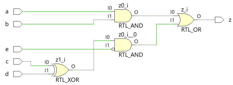
<노스크립트>  Always 블록을 사용하여 조합 논리를 모델링할 때 차단 할당 사용
테스트벤치는 설계가 예상대로 작동하는지 확인하기 위해 설계를 시뮬레이션하기 위한 플랫폼입니다. 모든 입력 조합은 for를 사용하여 설계 모듈로 구동됩니다. 일정 시간이 지난 후 새 값이 입력에 적용되도록 10시간 단위의 지연 문이 있는 루프.
module tb;
	// Declare testbench variables
  reg a, b, c, d, e;
  wire z;
  integer i;

  // Instantiate the design and connect design inputs/outputs with
  // testbench variables
  combo u0 ( .a(a), .b(b), .c(c), .d(d), .e(e), .z(z));

  initial begin
  	// At the beginning of time, initialize all inputs of the design
  	// to a known value, in this case we have chosen it to be 0.
    a <= 0;
    b <= 0;
    c <= 0;
    d <= 0;
    e <= 0;

    // Use a $monitor task to print any change in the signal to
    // simulation console
    $monitor ("a=%0b b=%0b c=%0b d=%0b e=%0b z=%0b",
              a, b, c, d, e, z);

    // Because there are 5 inputs, there can be 32 different input combinations
    // So use an iterator "i" to increment from 0 to 32 and assign the value
    // to testbench variables so that it drives the design inputs
    for (i = 0; i < 32; i = i + 1) begin
      {a, b, c, d, e} = i;
      #10;
    end
  end
endmodule
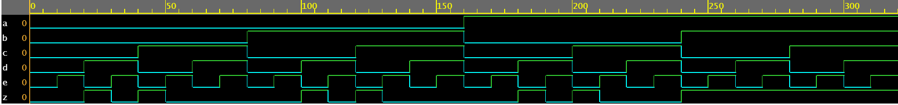
시뮬레이션 로그 ncsim> run a=0 b=0 c=0 d=0 e=0 z=0 a=0 b=0 c=0 d=0 e=1 z=0 a=0 b=0 c=0 d=1 e=0 z=1 a=0 b=0 c=0 d=1 e=1 z=0 a=0 b=0 c=1 d=0 e=0 z=1 a=0 b=0 c=1 d=0 e=1 z=0 a=0 b=0 c=1 d=1 e=0 z=0 a=0 b=0 c=1 d=1 e=1 z=0 a=0 b=1 c=0 d=0 e=0 z=0 a=0 b=1 c=0 d=0 e=1 z=0 a=0 b=1 c=0 d=1 e=0 z=1 a=0 b=1 c=0 d=1 e=1 z=0 a=0 b=1 c=1 d=0 e=0 z=1 a=0 b=1 c=1 d=0 e=1 z=0 a=0 b=1 c=1 d=1 e=0 z=0 a=0 b=1 c=1 d=1 e=1 z=0 a=1 b=0 c=0 d=0 e=0 z=0 a=1 b=0 c=0 d=0 e=1 z=0 a=1 b=0 c=0 d=1 e=0 z=1 a=1 b=0 c=0 d=1 e=1 z=0 a=1 b=0 c=1 d=0 e=0 z=1 a=1 b=0 c=1 d=0 e=1 z=0 a=1 b=0 c=1 d=1 e=0 z=0 a=1 b=0 c=1 d=1 e=1 z=0 a=1 b=1 c=0 d=0 e=0 z=1 a=1 b=1 c=0 d=0 e=1 z=1 a=1 b=1 c=0 d=1 e=0 z=1 a=1 b=1 c=0 d=1 e=1 z=1 a=1 b=1 c=1 d=0 e=0 z=1 a=1 b=1 c=1 d=0 e=1 z=1 a=1 b=1 c=1 d=1 e=0 z=1 a=1 b=1 c=1 d=1 e=1 z=1 ncsim: *W,RNQUIE: Simulation is complete.<노스크립트>
두 방법 모두 assign 및 always , 동일한 하드웨어 로직으로 구현하세요.
반가산기 모듈은 두 개의 스칼라 입력 a와 b를 받아들이고 조합 논리를 사용하여 출력 신호 sum 및 carry 비트 cout를 할당합니다. 합은 와 b 사이의 XOR에 의해 구동되는 반면 캐리 비트는 두 입력 사이의 AND에 의해 얻어집니다.
module ha ( input 	a, b,
						output	sum, cout);

	always @ (a or b) begin
		{cout, sum} = a + b;
	end

endmodule
<노스크립트> 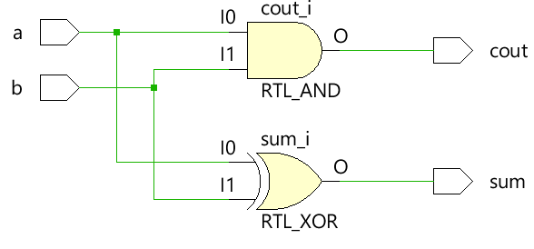
module tb;
	// Declare testbench variables
  reg a, b;
  wire sum, cout;
  integer i;

  // Instantiate the design and connect design inputs/outputs with
  // testbench variables
  ha u0 ( .a(a), .b(b), .sum(sum), .cout(cout));

  initial begin
  	// At the beginning of time, initialize all inputs of the design
  	// to a known value, in this case we have chosen it to be 0.
    a <= 0;
    b <= 0;

    // Use a $monitor task to print any change in the signal to
    // simulation console
    $monitor("a=%0b b=%0b sum=%0b cout=%0b", a, b, sum, cout);

    // Because there are only 2 inputs, there can be 4 different input combinations
    // So use an iterator "i" to increment from 0 to 4 and assign the value
    // to testbench variables so that it drives the design inputs
    for (i = 0; i < 4; i = i + 1) begin
      {a, b} = i;
      #10;
    end
  end
endmodule
시뮬레이션 로그 ncsim> run a=0 b=0 sum=0 cout=0 a=0 b=1 sum=1 cout=0 a=1 b=0 sum=1 cout=0 a=1 b=1 sum=0 cout=1 ncsim: *W,RNQUIE: Simulation is complete.<노스크립트>

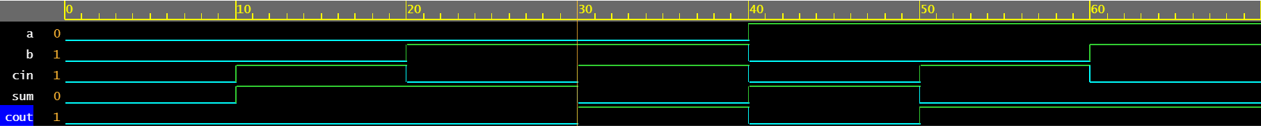
항상 블록을 사용하여 출력 합계 및 출력을 구동하는 전가산기의 동작을 설명할 수 있습니다.
module fa (	input 	a, b, cin,
			output reg	sum, cout);

  always @ (a or b or cin) begin
    {cout, sum} = a + b + cin;
  end

endmodule
<노스크립트> 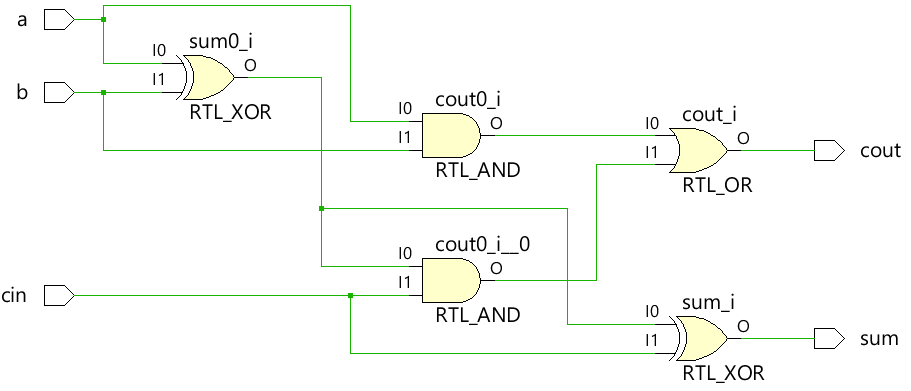
module tb;
  reg a, b, cin;
  wire sum, cout;
  integer i;

  fa u0 ( .a(a), .b(b), .cin(cin), .sum(sum), .cout(cout));

  initial begin
    a <= 0;
    b <= 0;

    $monitor("a=%0b b=%0b cin=%0b cout=%0b sum=%0b", a, b, cin, cout, sum);

    for (i = 0; i < 8; i = i + 1) begin
      {a, b, cin} = i;
      #10;
    end
  end
endmodule
시뮬레이션 로그 ncsim> run a=0 b=0 cin=0 cout=0 sum=0 a=0 b=0 cin=1 cout=0 sum=1 a=0 b=1 cin=0 cout=0 sum=1 a=0 b=1 cin=1 cout=1 sum=0 a=1 b=0 cin=0 cout=0 sum=1 a=1 b=0 cin=1 cout=1 sum=0 a=1 b=1 cin=0 cout=1 sum=0 a=1 b=1 cin=1 cout=1 sum=1 ncsim: *W,RNQUIE: Simulation is complete.<노스크립트>
간단한 2x1 멀티플렉서는 삼항 연산자를 사용하여 출력 c에 할당해야 하는 입력을 결정합니다. sel이 1이면 출력은 a에 의해 구동되고 sel이 0이면 b에 의해 출력됩니다.
module mux_2x1 (input 	a, b, sel,
				output 	reg c);


  always @ ( a or b or sel) begin
	c = sel ? a : b;
  end
endmodule
<노스크립트> 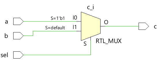
module tb;
	// Declare testbench variables
  reg a, b, sel;
  wire c;
  integer i;

  // Instantiate the design and connect design inputs/outputs with
  // testbench variables
  mux_2x1 u0 ( .a(a), .b(b), .sel(sel), .c(c));

  initial begin
  	// At the beginning of time, initialize all inputs of the design
  	// to a known value, in this case we have chosen it to be 0.
    a <= 0;
    b <= 0;
    sel <= 0;

    $monitor("a=%0b b=%0b sel=%0b c=%0b", a, b, sel, c);

    for (i = 0; i < 3; i = i + 1) begin
      {a, b, sel} = i;
      #10;
    end
  end
endmodule
시뮬레이션 로그 ncsim> run a=0 b=0 sel=0 c=0 a=0 b=0 sel=1 c=0 a=0 b=1 sel=0 c=1 ncsim: *W,RNQUIE: Simulation is complete.<노스크립트>

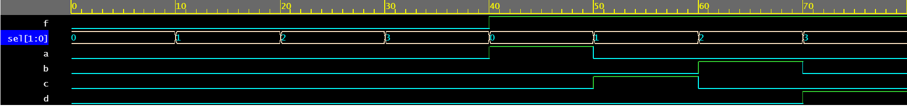
디멀티플렉서는 sel 및 f 입력의 조합을 사용하여 다른 출력 신호를 구동합니다. 각 출력 신호는 reg 유형입니다. always 내부에서 사용 민감도 목록에 나열된 신호의 변경 사항에 따라 업데이트되는 블록입니다.
module demux_1x4 (	input 				f,
										input [1:0]	 	sel,
										output reg		a, b, c, d);

  always @ ( f or sel) begin
    a = f & ~sel[1] & ~sel[0];
    b = f &  sel[1] & ~sel[0];
    c = f & ~sel[1] &  sel[0];
    d = f &  sel[1] &  sel[0];
  end

endmodule
<노스크립트> 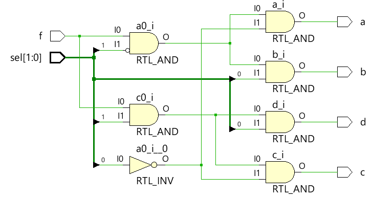
module tb;
	// Declare testbench variables
  reg f;
  reg [1:0] sel;
  wire a, b, c, d;
  integer i;

  // Instantiate the design and connect design inputs/outputs with
  // testbench variables
  demux_1x4 u0 ( .f(f), .sel(sel), .a(a), .b(b), .c(c), .d(d));

  // At the beginning of time, initialize all inputs of the design
  // to a known value, in this case we have chosen it to be 0.
  initial begin
    f <= 0;
    sel <= 0;

    $monitor("f=%0b sel=%0b a=%0b b=%0b c=%0b d=%0b", f, sel, a, b, c, d);

    // Because there are 3 inputs, there can be 8 different input combinations
    // So use an iterator "i" to increment from 0 to 8 and assign the value
    // to testbench variables so that it drives the design inputs
    for (i = 0; i < 8; i = i + 1) begin
      {f, sel} = i;
      #10;
    end
  end
endmodule
시뮬레이션 로그 ncsim> run f=0 sel=0 a=0 b=0 c=0 d=0 f=0 sel=1 a=0 b=0 c=0 d=0 f=0 sel=10 a=0 b=0 c=0 d=0 f=0 sel=11 a=0 b=0 c=0 d=0 f=1 sel=0 a=1 b=0 c=0 d=0 f=1 sel=1 a=0 b=0 c=1 d=0 f=1 sel=10 a=0 b=1 c=0 d=0 f=1 sel=11 a=0 b=0 c=0 d=1 ncsim: *W,RNQUIE: Simulation is complete.<노스크립트>
module dec_3x8 ( 	input 			en,
					input 	[3:0] 	in,
					output  reg [15:0] 	out);

  always @ (en or in) begin
    out = en ? 1 << in: 0;
  end

endmodule
<노스크립트> 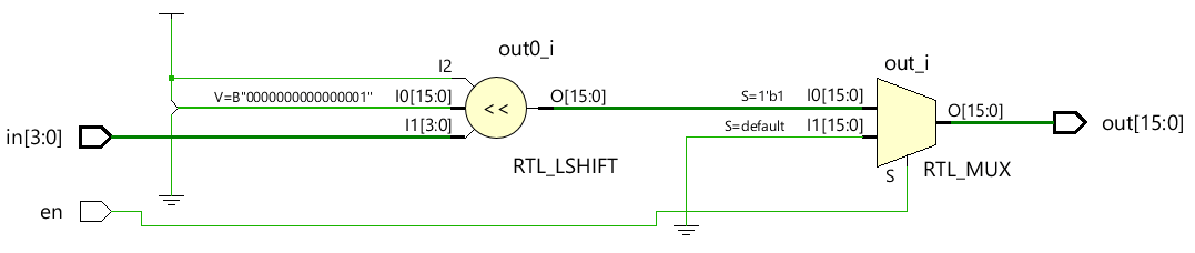
module tb;
  reg en;
  reg [3:0] in;
  wire [15:0] out;
  integer i;

  dec_3x8 u0 ( .en(en), .in(in), .out(out));

  initial begin
    en <= 0;
    in <= 0;

    $monitor("en=%0b in=0x%0h out=0x%0h", en, in, out);

    for (i = 0; i < 32; i = i + 1) begin
      {en, in} = i;
      #10;
    end
  end
endmodule
시뮬레이션 로그 ncsim> run en=0 in=0x0 out=0x0 en=0 in=0x1 out=0x0 en=0 in=0x2 out=0x0 en=0 in=0x3 out=0x0 en=0 in=0x4 out=0x0 en=0 in=0x5 out=0x0 en=0 in=0x6 out=0x0 en=0 in=0x7 out=0x0 en=0 in=0x8 out=0x0 en=0 in=0x9 out=0x0 en=0 in=0xa out=0x0 en=0 in=0xb out=0x0 en=0 in=0xc out=0x0 en=0 in=0xd out=0x0 en=0 in=0xe out=0x0 en=0 in=0xf out=0x0 en=1 in=0x0 out=0x1 en=1 in=0x1 out=0x2 en=1 in=0x2 out=0x4 en=1 in=0x3 out=0x8 en=1 in=0x4 out=0x10 en=1 in=0x5 out=0x20 en=1 in=0x6 out=0x40 en=1 in=0x7 out=0x80 en=1 in=0x8 out=0x100 en=1 in=0x9 out=0x200 en=1 in=0xa out=0x400 en=1 in=0xb out=0x800 en=1 in=0xc out=0x1000 en=1 in=0xd out=0x2000 en=1 in=0xe out=0x4000 en=1 in=0xf out=0x8000 ncsim: *W,RNQUIE: Simulation is complete.<노스크립트>

verilog
이전 기사에서는 always을 사용하는 다양한 예를 보여주었습니다. 조합 논리를 구현하는 블록. always 블록은 주로 순차를 구현하는 데 사용됩니다. 값을 저장할 수 있는 플립플롭과 같은 메모리 요소가 있는 논리입니다. JK 플립플롭 JK 플립 플롭은 값을 저장하는 데 사용되는 여러 유형의 플롭 중 하나이며 2개의 데이터 입력 j 및 k와 함께 리셋 rstn용 및 클록 clk용 하나가 있습니다. JK 플롭에 대한 진리표는 아래와 같으며 일반적으로 NAND 게이트를 사용하여 구현됩니다. 첫째 j k q 댓글 0 0 0 0
구성품 및 소모품 Arduino UNO × 1 근접 센서 × 1 점퍼 와이어(일반) × 1 이 프로젝트 정보 안녕하세요, 친구들! 오늘은 IR 센서를 Arduino UNO와 인터페이스하는 방법을 보여 드리겠습니다. 시작하겠습니다! 구성 요소 1. 아두이노 우노 2. 적외선 센서 3. LED 4.Arduio 케이블 5.점퍼 와이어 Arduino Uno는 무엇에 사용되나요? Arduino는 사용하기 쉬운 하드웨어 및 소프트웨어를 기