3D 프린팅


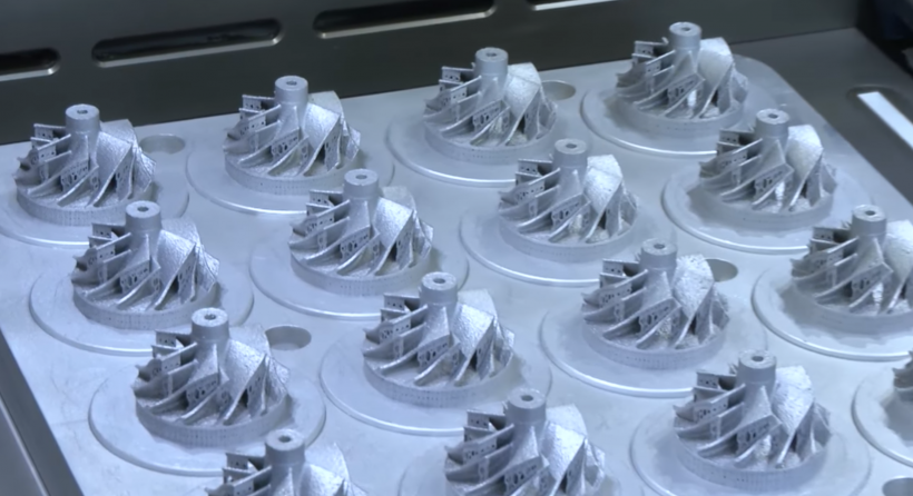
금속 3D 프린팅은 모든 면에서 빠르게 발전하고 있습니다. :기술이 더욱 발전하고 인쇄 속도가 빨라지고 산업 자재의 범위가 그 어느 때보다 다양해졌습니다. 이러한 발전은 이 기술에 대한 흥미롭고 새로운 응용 프로그램을 열어줍니다.
그러나 사용 가능한 기술을 파악하고 이를 기존 워크플로에 통합하는 것은 많은 회사에서 어려운 과제가 될 수 있습니다.
이 가이드는 현재 사용 가능한 기술부터 기술의 이점, 제한 사항 및 주요 응용 분야에 이르기까지 금속 3D 프린팅을 더 잘 이해할 수 있도록 돕는 것을 목표로 합니다.
현재 시장에서 사용할 수 있는 다양한 금속 3D 프린팅 기술이 있습니다. 각각의 장점과 한계가 있지만 금속 부품을 레이어별로 생성하는 기본 3D 프린팅 원칙에 의해 모두 통합됩니다.
일반적으로 사용되는 금속 3D 프린팅 기술은 다음과 같습니다.
<울>
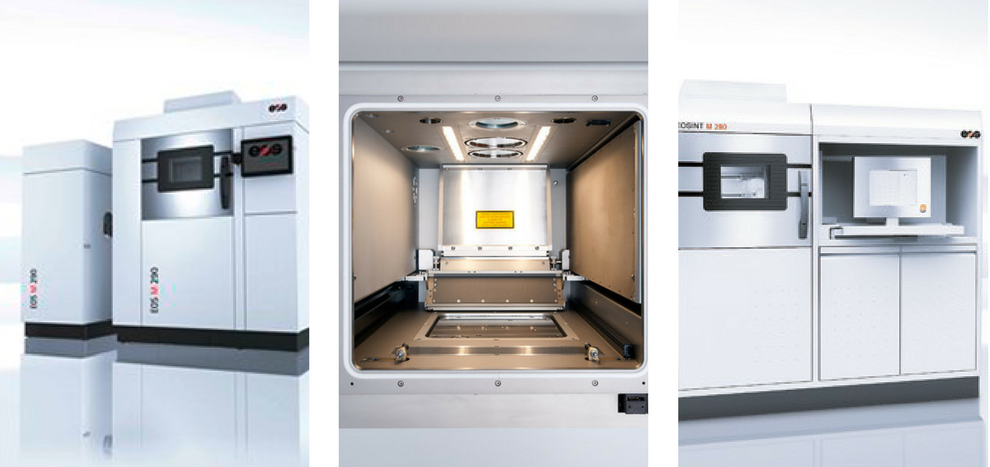
모든 금속 3D 프린팅 기술 중에서 금속 파우더 베드 퓨전(Powder Bed Fusion)이 가장 잘 알려져 있습니다.
Powder Bed Fusion 기술을 사용하면 분말 금속 층이 기계의 빌드 플랫폼에 고르게 분포되고 에너지원(레이저 또는 전자빔)에 의해 선택적으로 함께 융합됩니다.
파우더 베드 퓨전 카테고리에 속하는 두 가지 주요 금속 3D 프린팅 프로세스가 있습니다.
<울>선택적 레이저 용융 및 직접 금속 레이저 소결
IDTechEx Research의 보고서에 따르면 SLM과 DMLS는 가장 지배적인 금속 3D 프린팅 기술이며 DMLS는 전 세계적으로 가장 큰 설치 기반을 가지고 있습니다.
SLM과 DMLS를 사용하면 강력하고 미세 조정된 레이저가 금속 분말 층에 선택적으로 적용됩니다. 이러한 방식으로 금속 입자가 함께 융합되어 부품을 만듭니다.
두 기술의 중요한 요구 사항은 아르곤과 같은 불활성 가스로 채워진 밀폐된 빌드 챔버입니다. 이는 금속 분말의 산소 오염을 방지하고 인쇄 과정에서 올바른 온도를 유지하는 데 도움이 됩니다.
전자빔 용해
파우더 베드 퓨전 제품군의 또 다른 3D 프린팅 프로세스는 전자빔 용융(EBM)입니다. EBM은 금속 분말도 용융되어 완전히 조밀한 금속 부품을 생성한다는 점에서 SLM과 유사하게 작동합니다.
분말의 오염 및 산화를 방지하기 위해 EBM 공정은 진공 환경에서 진행됩니다.
SLM/DMLS와 EBM 기술의 주요 차이점은 에너지원입니다. EBM 시스템은 레이저 대신 고출력 전자빔을 열원으로 사용하여 금속 분말 층을 녹입니다.
EBM은 또한 SLM 및 DMLS와 비교할 때 정확도가 낮은 금속 부품을 생산하는 경향이 있습니다. 이는 SLM 프로세스의 레이어 두께가 EBM(50~200미크론)보다 일반적으로 더 얇기 때문에(50~200미크론) 더 정확한 인쇄 결과를 얻을 수 있습니다.
전자빔은 일반적으로 레이저보다 강력하기 때문에 EBM은 고온 금속 초합금과 함께 제트 엔진 및 가스 터빈과 같은 매우 까다로운 응용 분야용 부품을 만드는 데 종종 사용됩니다. 생산된 금속 부품은 고밀도이므로 항공우주 산업에 이상적입니다.
EBM 시스템의 높은 비용은 이 기술에 투자하려는 기업이 고려해야 할 사항입니다. 또한 이 기술은 전하에 의존하기 때문에 EBM은 티타늄 및 크롬-코발트 합금과 같은 전도성 금속에만 사용할 수 있습니다.
SLM/DMLS 또는 EBM 여부에 관계없이 Powder Bed Fusion 기술로 생산된 모든 금속 부품에는 일종의 후처리가 필요합니다. 후처리는 부품의 미학을 개선할 뿐만 아니라 기계적 특성을 개선하고 특히 까다로운 애플리케이션의 경우 정확한 설계 매개변수를 충족하기 위해 필요합니다.
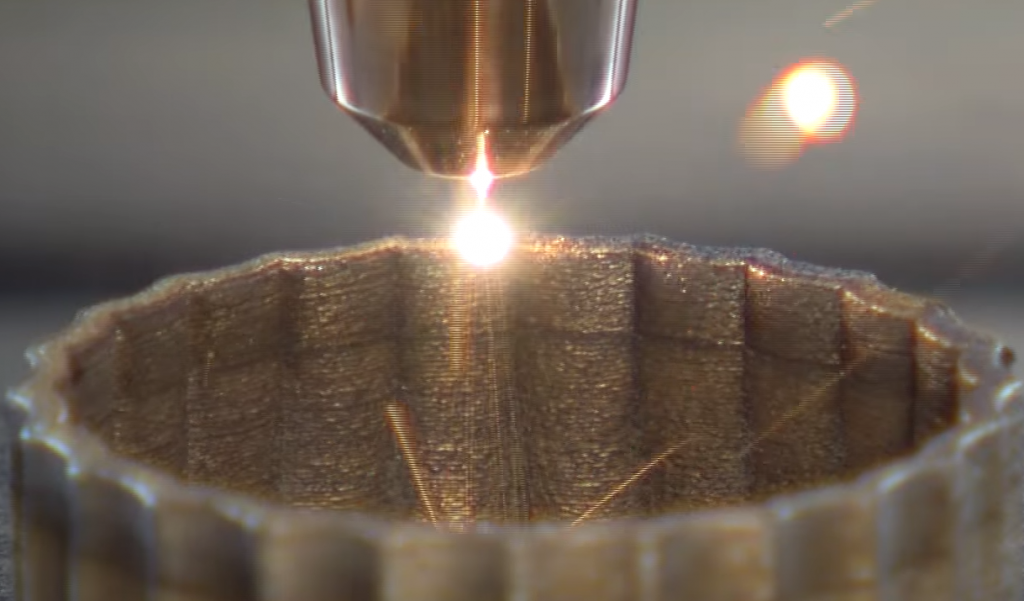
[이미지 제공:하이브리드 제조 기술 ]
DED(직접 에너지 증착)는 노즐을 통해 빌드 플랫폼에 증착될 때 레이저 또는 전자 빔으로 금속 재료를 녹여서 작동합니다. 일반적으로 DED 기계는 재료 증착 속도가 빠르며 분말 또는 와이어 형태의 금속 재료로 작업할 수 있으므로 거의 그물 모양의 고밀도 부품을 생성할 수 있습니다.
일반적으로 작지만 매우 정확한 구성 요소를 생산하는 파우더 베드 퓨전 공정과 달리 일부 독점 DED 방법은 더 큰 금속 부품을 생산할 수 있습니다.
길이 6미터 이상의 부품을 생산할 수 있다고 알려진 미국 Sciaky의 EBAM(Electron Beam Additive Manufacturing) 기술이 그 한 예입니다.
DED 기술은 기존 제조 방법으로는 수리가 어렵거나 불가능한 터빈 블레이드 및 사출 성형 도구 인서트와 같은 손상된 부품을 수리하는 데 매우 적합합니다.
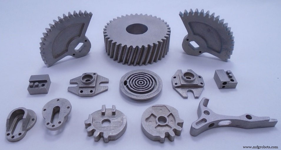
Metal Binder Jetting은 시장에서 사용할 수 있는 가장 비용 효율적인 금속 3D 프린팅 기술 중 하나입니다.
종이에 잉크를 인쇄하는 것과 유사하게 Metal Binder Jetting은 프린트 헤드를 사용합니다. 이 프린트 헤드는 빌드 플랫폼 위로 이동하여 금속 분말 층에 결합제의 방울을 떨어뜨립니다. 이 과정을 통해 금속 입자가 함께 융합되어 부품을 만듭니다.
여러 개의 프린트 헤드를 사용하여 인쇄 속도를 높일 수 있습니다.
Metal Binder Jetting 기계는 더 빠른 인쇄 속도와 많은 양의 인쇄를 제공합니다. 또한 파우더 베드 시스템보다 훨씬 저렴한 경향이 있습니다.
그러나 Metal Binder Jetting을 사용하여 생산된 부품은 인쇄 공정의 특성상 기계적 특성에 한계가 있습니다. 인쇄 과정에서 바인더가 소진되기 때문에 다공성이 매우 높습니다.
결과적으로 부품은 최종 사용 전에 상당한 후처리가 필요합니다. 이러한 단계에는 부품을 경화시키기 위한 경화, 다공성을 줄이고 강도를 증가시키기 위한 소결 및 청동 침투가 포함됩니다.
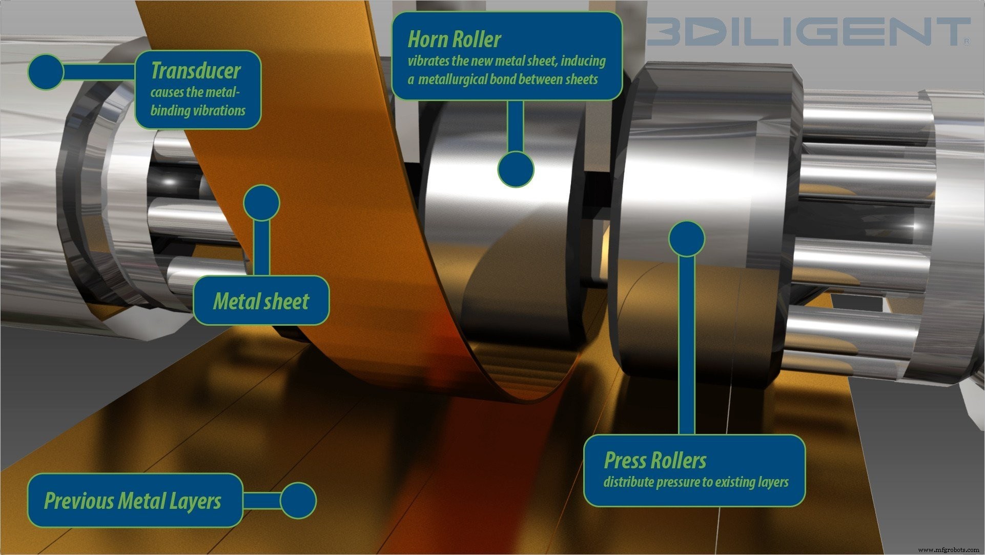
초음파 시트 라미네이션은 저온 하이브리드 금속 적층 제조 공정입니다.
이 기술은 압력 하에서 초음파 진동과 함께 얇은 금속 호일을 용접하여 작동합니다. 인쇄 프로세스가 완료되면 CNC 밀링이 적용되어 초과 재료를 제거하고 부품을 마무리합니다.
Ultrasonic Sheet Lamination은 저온 공정이기 때문에 금속 재료를 녹이지 않습니다. 이 공정은 또한 이종 금속 유형을 함께 융합할 수 있습니다.
이 기술의 주요 이점은 저렴한 비용, 빠른 인쇄 속도 및 다양한 금속의 전자 및 센서가 내장된 부품을 생성할 수 있다는 점입니다.
금속 3D 프린팅의 급속한 발전과 함께 하드웨어 제조업체는 지속적으로 새로운 프로세스를 개발하기 위해 노력하고 있습니다. 아래에서는 속도와 비용 면에서 금속 3D 프린팅에 혁명을 일으킬 잠재력이 있는 새로 개발된 몇 가지 금속 3D 프린팅 기술에 대해 설명했습니다.
압출 기반 금속 3D 프린팅
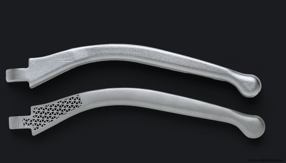
금속 필라멘트의 압출을 통해 부품을 적층적으로 생산하는 것은 비교적 새로운 접근 방식입니다.
이 분야에서 가장 유명한 두 회사는 Markforged와 Desktop Metal입니다. 두 회사는 2017년 금속 3D 프린팅 시스템(Markforged의 Metal X 및 Desktop Metal의 Studio System)을 처음 공개했습니다.
압출 기반 금속 3D 프린팅은 FDM(Fused Deposition Modeling)과 유사하게 작동합니다. 여기서는 필라멘트가 가열되어 노즐을 통해 압출되어 레이어별로 부품이 생성됩니다.
그러나 FDM에서 사용되는 플라스틱 필라멘트와 달리 금속 압출은 금속 분말로 만든 필라멘트 또는 플라스틱 바인더에 펠릿을 싸서 사용합니다.
부품이 인쇄되면 '녹색 상태'로 유지되며 추가 후처리 단계를 거쳐야 합니다. 즉, 남아 있는 플라스틱을 태우기 위한 디바인딩 및 금속 입자를 함께 융합하기 위한 소결입니다.
압출 기반 금속 3D 프린팅은 가장 저렴한 금속 적층 제조 공정 중 하나입니다. 이는 부분적으로 분말층 공정에 사용되는 금속 분말보다 훨씬 저렴한 MIM(금속 사출 성형) 재료를 사용하기 때문입니다.
재료 분사
Material Jetting은 프린트 헤드를 사용하여 액체 형태의 광반응성 재료를 빌드 플랫폼에 레이어별로 증착하는 잉크젯 인쇄 프로세스입니다.
Material Jetting은 일반적으로 매우 정확한 풀 컬러 플라스틱 모델을 만들기 위한 프로토타입 기술로 사용되었습니다.
그러나 한 회사는 금속 3D 프린팅 기술의 잠재력을 인식했습니다. 이스라엘 회사인 XJet은 높은 수준의 디테일과 마감을 달성할 수 있는 금속용 새로운 잉크젯 기술을 개발했습니다.
XJet의 NPJ(NanoParticle Jetting™) 기술은 프린트 헤드를 사용하여 액체 제형에 현탁된 금속 잉크를 증착합니다. 이 과정은 가열된 챔버에서 진행됩니다.
금속 잉크가 침착되면 뜨거운 건물 트레이에 침착되어 액체 제제를 증발시켜 금속 입자만 남깁니다. 입자에는 결합제가 작게 코팅되어 있어 세 축 모두에서 서로 결합할 수 있습니다.
인쇄가 완료되면 부품은 소결 과정을 거치는 오븐으로 옮겨집니다. 이 기술은 기능적 프로토타이핑과 중소 금속 부품의 주문형 제조에 모두 사용할 수 있습니다.
메탈 제트(HP)
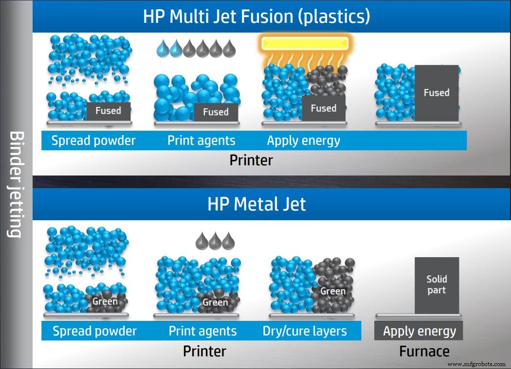
HP는 2016년 폴리머 Multi Jet Fusion 시스템을 출시하면서 처음으로 3D 프린팅 시장에 진출하여 파장을 일으켰습니다. 2018년에 회사는 새로운 금속 3D 프린팅 시스템인 Metal Jet를 발표함으로써 바인더 분사 기술을 한 단계 더 발전시켰습니다.
Metal Jet 시스템은 더 빠르고 저렴한 인쇄를 가능하게 하도록 개선된 HP의 바인더 젯팅 프로세스를 기반으로 합니다.
다른 바인더 분사기와 유사하게 작동하지만 이 시스템은 HP의 Latex 잉크 기술의 도움으로 개발된 독점 바인더를 사용합니다. 이 새로운 바인더 제형은 부품 소결을 더 빠르고 저렴하며 훨씬 간단하게 만든다고 합니다.
또한 Metal Jet는 MIM(금속 사출 성형) 분말을 사용하며 ASTM 표준을 충족하는 등방성 부품을 생산할 수 있습니다.
이 기술의 주요 특징 중 하나는 증가된 프린트 헤드로 현재 시장에 나와 있는 유사한 바인더 및 레이저 소결 기계보다 생산성이 최대 50배 더 높다고 합니다.
줄 인쇄(디지털 합금)
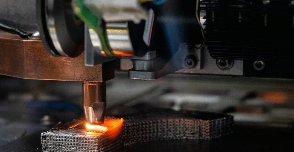
상업 출시는 2020년이 되지 않지만 Digital Alloys의 특허 받은 Joule Printing 기술은 여기서 언급할 가치가 있는 또 다른 금속 3D 프린팅 공정입니다.
줄 인쇄는 분말이 아닌 금속 와이어를 사용하는 고속 기술입니다.
금속 와이어는 정밀 와이어 공급으로 정밀 모션 시스템에 공급됩니다. 와이어가 배치되면 전류는 와이어를 통해 전달되고 이어서 인쇄 베드와 부품 자체로 전달됩니다. 금속 와이어는 프린트 헤드가 움직일 때 전류에 의해 녹고 금속 방울이 함께 융합되어 최종 부품을 형성합니다.
줄 프린팅 기술은 거의 순수한 형태의 부품 생산을 가능하게 하며 자동차, 항공 우주 및 소비재 산업 내에서 도구 및 기타 응용 분야에 사용될 수 있습니다.
MELD(MELD 제조)
MELD Manufacturing Corporation은 금속 부품을 제조하기 위한 새로운 고체 금속 3D 프린팅 공정을 개발했습니다. 고체 상태라는 것은 인쇄 과정에서 금속 재료를 녹일 필요가 없다는 것을 의미합니다.
대신, 이 프로세스는 중공 회전 도구를 통해 금속 재료를 통과시키는 것을 포함합니다. 이 도구에서 극도의 압력과 마찰이 작용하여 추가되는 재료와 이미 증착된 재료를 변형시킵니다.
이 프로세스는 생산된 부품이 높은 강도와 내식성과 같은 기계적 특성을 갖도록 합니다.
MELD 기술로 인쇄된 부품은 완전히 조밀하며 후속 열처리가 필요하지 않습니다. 또한 이 기술은 부품을 만드는 데 적합할 뿐만 아니라 기존 구성 요소를 코팅하고 수리하는 데에도 적합합니다.
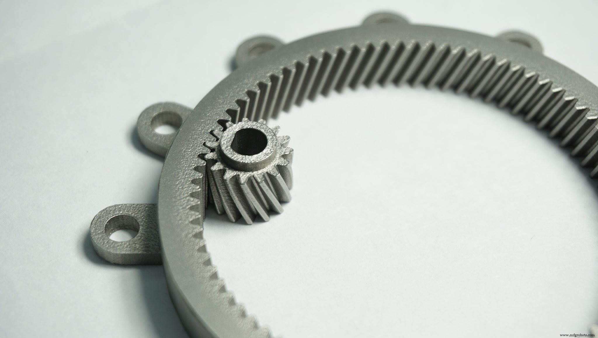
금속 3D 프린팅은 기존 제조 공정에서는 불가능한 수준의 복잡성과 맞춤화를 제공하여 부품 제조 방식을 변화시킬 잠재력이 있습니다.
금속 3D 프린팅에 투자할지 여부를 결정할 때 회사가 이 기술의 이점을 누릴 수 있는지 평가하는 것이 중요합니다. 아래에서 금속 3D 프린팅의 주요 이점 중 일부를 간략하게 설명했습니다.
첫째, 3D 프린팅은 값비싼 툴링과 금형의 필요성을 제거하여 제조업체가 비싸고 시간이 많이 소요되는 설정 비용을 제거할 수 있도록 합니다. 둘째, 설계에서 생산으로 이동할 수 있으므로 리드 타임을 몇 주 또는 몇 달에서 며칠로 크게 단축할 수 있습니다.
마지막으로 3D 프린팅으로 부품 어셈블리를 통합하는 기능은 노동 시간과 비용을 크게 절약하는 데 도움이 될 수 있습니다.
전통적인 감산 제조 방법은 막대한 재료 낭비를 수반하며, 한 연구에 따르면 금속 블록에서 재료를 절단하기 위해 CNC 밀링 머신을 사용하면 재료 낭비가 최대 95%까지 발생할 수 있습니다.
이에 비해 금속 3D 프린팅 공정은 필요한 경우에만 재료를 소결하거나 녹이기 때문에 폐기물이 훨씬 적게 발생합니다. 어떤 경우에는 소결되지 않은 금속 분말을 재사용할 수도 있습니다.
결과적으로 3D 프린팅을 통한 재료 사용은 매우 효율적이며 재료 폐기율은 일반적으로 5% 미만입니다.
금속 3D 프린팅은 복잡한 형상을 생산하는 데 사용할 수 있어 제조의 한계를 뛰어 넘습니다. 이러한 복잡한 디자인은 기존 프로세스보다 비용 효율적으로 생산할 수 있습니다.
토폴로지 최적화 및 생성 설계와 같은 설계 도구와 결합된 3D 프린팅은 기능과 기계적 특성이 향상된 경량 금속 부품을 만드는 데 사용할 수 있습니다.
따라서 이러한 소프트웨어 설계 도구는 새롭고 혁신적인 설계 가능성을 여는 데 도움이 될 수 있습니다. 예를 들어, 격자 구조는 금속 부품의 무게를 줄여 차량이나 항공기의 성능을 향상시키기 위한 설계에 포함될 수 있습니다.
3D 프린팅을 사용하면 소량 생산이 경제적으로 가능해집니다.
높은 툴링 비용으로 인해 기존 제조 방법은 소량의 부품을 생산하기 위해 구현하는 데 매우 비용이 많이 들 수 있습니다.
대조적으로, 3D 프린팅은 툴링이 필요하지 않으므로 소량 생산에 더 비용 효율적인 옵션입니다. 이것의 한 가지 주요 예는 제품을 일회성 또는 소량 배치의 일부로 생산해야 할 수 있는 맞춤형 부품의 경우입니다.
3D 프린팅을 사용하여 주문형 부품을 만들 수도 있습니다. 예를 들어, 기업은 필요에 따라 도구와 예비 부품을 사내에서 3D 프린팅할 수 있습니다. 이를 통해 부품 재고를 비축할 필요가 줄어들고 물류 및 전체 공급망이 간소화됩니다.
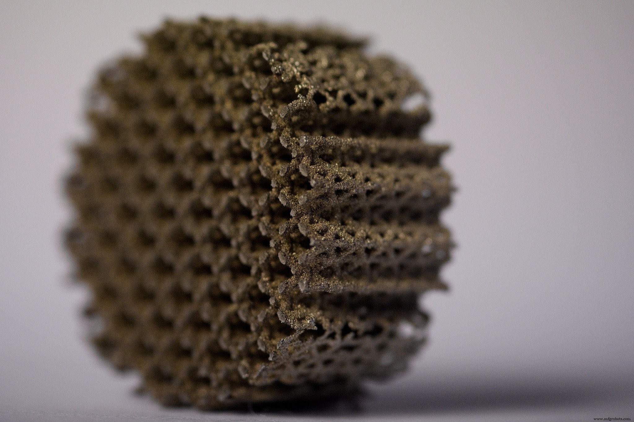
금속 3D 프린팅의 이점은 분명하지만 기술을 성공적으로 구현하는 데는 어려움이 있습니다. 아래에서는 현재 금속 3D 프린팅 시장이 직면한 몇 가지 주요 과제를 다룹니다.
지난 10년 동안 3D 프린터의 가격이 크게 하락했지만 금속 AM 시스템의 비용은 여전히 이 기술에 투자하려는 회사의 주요 과제 중 하나입니다.
현재 금속 3D 프린터의 가격은 수십만 달러, 심지어는 100만 달러 이상입니다.
동시에, 현재 시장에 나와 있는 금속 재료는 일반적으로 상당히 제한적이며 비용은 전통적인 금속 제조에 사용되는 금속보다 훨씬 높습니다.
그러나 향후 몇 년 동안 금속 재료 과학의 발전으로 3D 인쇄 가능한 금속의 선택이 확대되고 비용이 절감될 것으로 기대합니다.
금속 3D 프린팅과 관련된 여러 변수로 인해 폴리머 3D 프린팅보다 훨씬 복잡한 공정이 됩니다. 현재 많은 기업들이 금속 3D 프린터를 사내에서 성공적으로 운영하는 데 필요한 전문 지식이 부족합니다.
이 기술을 시작하는 한 가지 가능한 방법은 금속 3D 프린팅 서비스 제공업체와 협력하는 것입니다. 서비스 사무소는 올바른 금속 AM 기술 및 재료 선택에 대한 전문 지식을 제공할 수 있습니다.
AM 기술을 사내에 도입하려는 기업의 경우 AM 전략을 개발하고 구현하는 것이 이 여정의 핵심 첫 단계가 될 것입니다.
부품 품질과 공정 반복성은 제조업체의 주요 관심사입니다. 금속 3D 프린팅의 경우 부품 품질에 영향을 미칠 수 있는 다양한 변수가 있습니다. 이러한 변수는 설계에서 빌드 준비 및 후처리에 이르는 전체 AM 워크플로에 걸쳐 있습니다.
그러나 반복 가능한 고품질 금속 부품을 가능하게 하기 위해 이러한 변수를 제어하는 것은 여전히 어려운 일입니다.
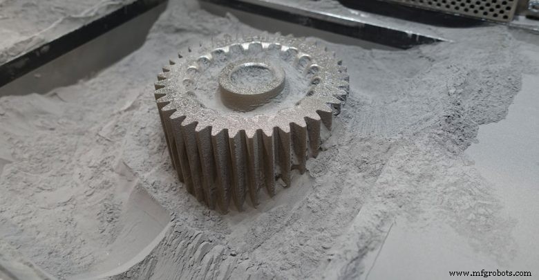
금속은 2012년 이후 3D 프린팅 재료 시장에서 가장 빠르게 성장하는 부문이었습니다.
금속 3D 프린팅 공정은 고품질 금속 재료를 사용합니다. 일반적으로 분말 형태로 생산되며 입자 모양 및 크기, 분말 밀도와 같은 특정 특성을 충족해야 합니다.
기존 제조 공정과 비교할 때 사용 가능한 3D 인쇄 가능한 금속의 범위는 여전히 제한적입니다.
이는 금속 3D 프린팅 기술에 맞게 조정되거나 생산되는 특수 재료가 개발되는 데 몇 년이 걸릴 수 있다는 사실 때문입니다.
그러나 DED와 같은 일부 공정은 원래 기존 공정을 위해 개발된 금속(예:와이어 형태)을 사용할 수 있습니다.
현재 금속 3D 프린팅에 가장 일반적으로 사용되는 재료는 알루미늄, 티타늄, 스테인리스강과 같은 경량 금속입니다.
그러나 내화 금속 및 코발트 크롬 합금의 사용도 확대되고 있으며, 이는 주로 항공 우주 및 석유 및 가스 산업의 응용 분야에 의해 주도됩니다.
아래 표에서 더 일반적인 금속 3D 프린팅 재료와 일반적인 응용 분야를 식별했습니다.
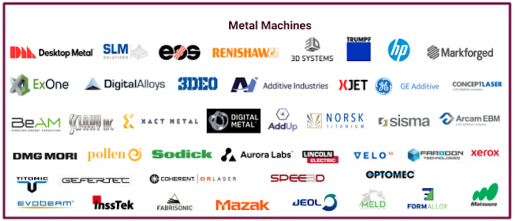
금속 3D 프린팅이 증가함에 따라 시장에서 사용 가능한 금속 3D 프린터의 수가 확장되고 있습니다.
2018 Wohlers Report에 따르면 금속 AM 시스템 판매는 2017년에 80% 성장했으며 시장에 진입하는 금속 AM 시스템 제조업체의 수가 증가했습니다.
다운로드 가능한 표에는 분말 베드 기술, DED, 바인더 제팅 및 압출 기반 금속 3D 프린팅을 사용하는 금속 3D 프린터의 주요 제조업체가 요약되어 있습니다. 완전한 목록은 아니지만 시장에 나와 있는 주요 기계 제조업체에 대한 높은 수준의 개요를 제공합니다.
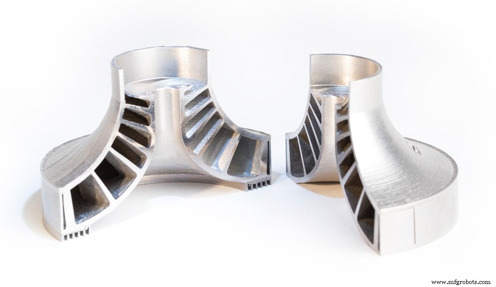
Metal 3D printing has found its niche in a number of industries, with players in the aerospace, automotive and medical industries at the forefront of driving innovation with the technology.
In this section, we take a look at the most common applications for the technology, as well as key use cases that have unlocked the benefits of metal 3D printing.
Industry Common applications Aerospace Fuel injectors, blades, combustor liners, rocket engine manifolds, brackets, functional prototypes Automotive Air ducts, brackets, uprights, knuckles, turbochargers, suspension assemblies, transmission plates, brake calipers, manifolds Medical and dental Custom-fit dental restorations, such as stages, crowns, and bridges; customised orthopaedic implants (hip, knee, and spinal), surgical tools Industrial goods Tool inserts with conformal cooling channels, industrial pump components, bearings, stators, heat exchangers, impellers, tooling repair
The aerospace industry has been a huge pioneer of metal 3D printing. By using the technology, aerospace companies hope to produce more efficient, lightweight aircraft parts to improve aircraft performance.
Within the aerospace industry, metal 3D printing is used in a range of applications, from functional prototypes to tooling, replacement parts and structural aircraft components.
General Electric
A great example is General Electric (GE), which is extensively using metal 3D printing to make and develop new products. GE’s subsidiary, GE Aviation, is producing fuel nozzles for the LEAP family of jet engines, with an aim to manufacture 100,000 fuel nozzles by 2020.
Having achieved the milestone of 30,000 3D-printed fuel nozzles in October 2018, GE looks like it’s well on its way to fulfilling this goal.
Using advanced design tools and Electron Beam Melting technology, GE’s engineers were able to create a fuel nozzle 25% lighter and 15% more fuel efficient than its traditionally produced counterpart.
The breakthrough in this case is that the fuel nozzle was printed as a single unit, whereas previous models incorporated 20 separate parts which needed to be subsequently assembled.
But GE has not stopped here. The company is also building its GE Catalyst, an advanced turboprop engine that has more than a third of its components 3D printed in various metals.
Similar to its fuel nozzles, the engineers behind the turboprop have achieved considerable part consolidation, reducing the number of parts produced from 855 to just 12. A redesign will also help to reduce the fuel burn of an engine by as much as 20%.
Automakers have been using 3D printing since the technology’s early days — Ford Motor Company, for example, notably bought the third 3D printer ever made.
For many years, metal 3D printing has proved to be a cost-effective tool for prototyping and producing jigs and fixtures. However, advancements with the technology mean that more opportunities are opening up for end-part production.
Automotive companies can use metal 3D printing to create lightweight metal parts, leading to enhanced vehicle performance and lower fuel consumption. This is particularly beneficial for the motorsports industry, where 3D-printed car parts can offer racing teams significant performance advantages.
Another area of interest for the industry is also using 3D printing to produce spare parts that are typically produced in low volumes. 3D printing spare parts on demand enables automakers to receive parts at the point of need, reducing inventory costs and increasing agility.
BMW
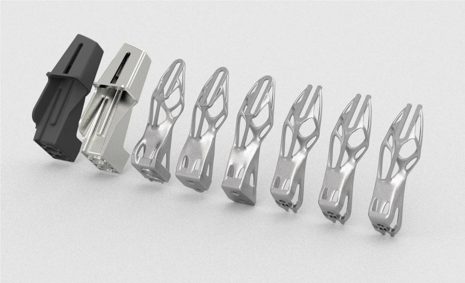
BMW is another company using 3D printing extensively. Most notably, the company has recently moved into the series production of a 3D-printed metal component for its 2018 BMW i8 Roadster vehicle.
Using topology optimisation, designers were able to optimise the vehicle’s roof bracket — a fixture for the folding/unfolding mechanism of the vehicle’s soft top. 3D printed in aluminium alloy powder (AlSi10Mg), the new roof bracket is 44% lighter than its conventionally made counterpart.
Furthermore, engineers optimised the design of the bracket to eliminate support structures. By doing so, the team was able to increase throughput from 51 to 238 of these parts per platform. This makes BMW’s roof bracket the first automotive component to be mass-produced with the help of metal 3D printing.
Bugatti
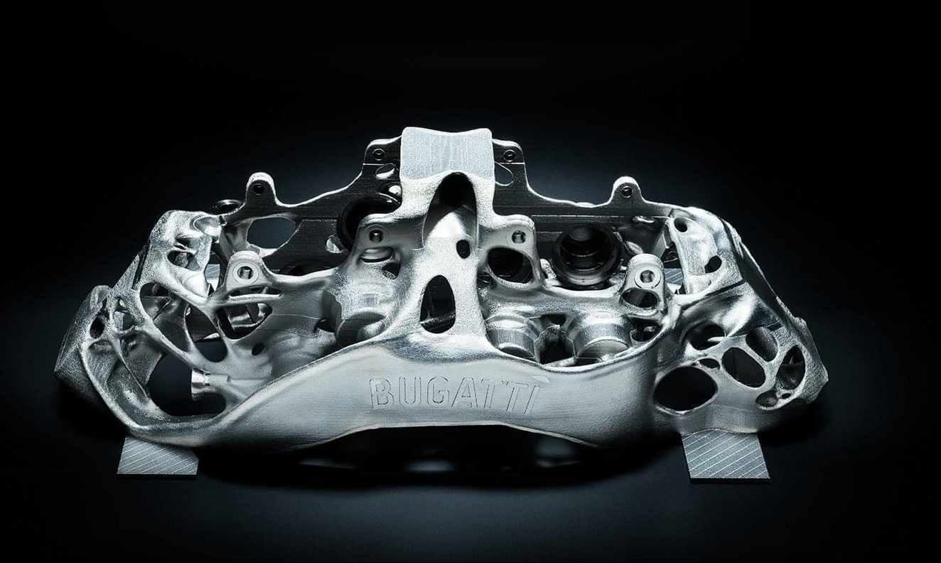
An exciting application of metal 3D printing comes from luxury car manufacturer, Bugatti. The French automaker has developed a 3D-printed brake caliper to be used on its Bugatti Chiron supercar.
An essential part of the braking system, the brake caliper has been made lighter and stronger thanks to 3D printing. Measuring 41 x 21 x 13.6 cm, the part took 45 hours to print using SLM technology and titanium powders.
By using 3D printing, Bugatti also achieved a 40% weight reduction for the caliper, when compared to machined aluminium alternative.
In 2018, the company successfully tested the brake caliper, proving that it can meet extreme strength, stiffness and temperature requirements.
Audi
Audi presents a different business case for metal 3D printing. In this case, the German automaker is using the technology to produce spare parts that are in low demand.
Metal 3D printing allows Audi to produce these parts on demand, producing and supplying spare parts as they are needed. This in turn greatly simplifies logistics and warehousing.
Audi identified that smaller, complex components would be most suited for metal 3D printing. A good example of a component is water adapters, which Audi is already producing for the Audi W12 engine. The company says that the load capacity of the components is comparable to that of parts manufactured using traditional methods.
In the medical field, metal 3D printing allows highly customised medical devices, like orthopedic implants, to be created.
It’s far from unusual for off-the-shelf orthopaedic implants to be used for replacement surgeries. However, prefabricated implants can sometimes cause problems after the surgery as they don’t always fit properly.
To avoid this, 3D printing is increasingly being used to create customised, patient-specific implants with improved functionality.
For example, implants can be designed with improved porosity and surface texture, facilitating the growth of the tissue around the implant. This level of complexity can only be achieved with 3D printing. SmarTech Publishing predicts that more than 2 million implants will be 3D printed in metal by 2025.
Additionally, metal 3D printing can be used to create hip and knee joint replacements, cranial reconstruction implants and spinal implants.
Lima Corporate
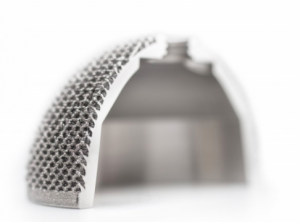
Italian medical device manufacturer Lima Corporate has been bringing additively manufactured hip implants to market for 10 years, using Electron Beam Melting (EBM) technology.
The company developed a technology for 3D printing biocompatible titanium in cellular solid structures that resemble natural bone. Such structures are used to coat an implant, allowing it to be better integrated with human tissue.
The technology is said to have helped almost 100,000 patients, enabling better implant performance and outcomes.
When it comes to the design and manufacture of tooling equipment, 3D printing can empower engineers to overcome traditional limitations. This can mean being able to create a mould or core in a matter of days instead of months, significantly reducing lead times.
Within the injection moulding industry, moulds are typically CNC-machined. Here, production costs can range from from $20,000 to hundreds of thousands of dollars. Lead times can last between 2 to 4 months. Additionally, moulds can often require multiple design iterations to achieve the final design, a costly and time-intensive process.
However, metal 3D printing can overcome these inefficiencies in several ways. First, the technology enables rapid design iterations, enabling changes to be made with relative ease.
Second, the performance of tooling aids and components can be enhanced with additive manufacturing.
For example, conformal cooling channels, lattice structures, and complex core/cavity shapes, which are too expensive or impossible to manufacture traditionally, can be factored into a mould design and 3D printed.
Conformal cooling channels are particularly beneficial as they help to achieve more homogenous heat transfer within the mould, compared to traditionally drilled straight-line cooling channels, resulting in greater cooling characteristics.
GW Plastics 3D prints moulds with conformal cooling
GW Plastics, US-based mould maker, has invested in hybrid metal 3D printing with the goal of building injection moulds with conformal cooling. One of the key reasons for this investment is faster cycles and better part quality enabled by 3D-printed moulds.
In fact, the company says 3D-printed moulds can save up to 30% of the cycle time by reducing cooling time. Furthermore, metal 3D printing allows GW Plastics to print a mould as a single piece, thus eliminating the need to assemble multiple components.
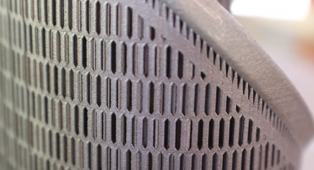
Post-processing is an unavoidable step when 3D printing metal parts. Post-processing helps to improve the mechanical properties, geometrical accuracy and aesthetics of a part, ensuring that a part meets the required design specifications.
Before printing your part, it’s important to understand the various post-processing methods that can be used to finish a metal part.
In this section, we’ll be looking at some of the main post-processing steps that can help to achieve the necessary finish for metal 3D-printed parts.
High temperatures and subsequent cooling are a common occurrence during the metal 3D printing process. However, when a metal part is subjected to such extreme temperature changes, this can lead to residual stress.
To avoid deformations that can occur as a result of a build-up of residual stress, parts produced with powder bed processes must undergo a stress relieving cycle. The number of stress relief cycles depends on the metal or alloy used to produce a part.
In order to protect the surface of a part from oxidation, the stress relieving heat treatment takes place in an inert (typically argon) atmosphere. Parts are typically heat treated while still attached to the build platform.
During the stress relieving cycle, the whole platform is placed in a furnace, where the part is heated to a temperature range between 550-675°C for 1 to 2 hours and then cooled down slowly. Stress corrosion cracking can also be reduced through this stress relief process.
Secondary heat treatment like Hot Isostatic Pressing (HIP) helps to improve the microstructure and mechanical properties of a metal part.
With HIP, high temperatures (up to 2200ºC) and isostatic inert gas pressure (from 100 to 3100 bar) are applied to a part to achieve the highest possible density, reduce porosity and eliminate internal voids.
The HIP treatment of metal parts results in optimum mechanical properties that can be compared with wrought and cast alloys.
Important to note is that the natural cooling in an HIP system can take between 8 and 12 hours. However, HIP systems powered by uniform rapid cooling technologies have been developed, allowing for the parts to be cooled from 1,260 to 300°C in less than 30 minutes.
With powder bed processes, a printed part is encapsulated in the unused powder which needs to be removed once the printing process is complete. The excess powder can be removed manually or automatically with the help of specialised equipment, and then recycled for later use.
The removal of any unmelted powder trapped inside a part should also be taken into consideration. For this reason, at least two escape holes should be factored into the design to help easily remove powder after printing.
Once a part has been printed, it will need to be removed from the build platform. Build plates are then machined separately to remove excess material and return them to a usable state.
Wire Electrical Discharge Machining (WEDM) is the process of choice for cutting metal parts away from their build plates. WEDM involves creating electrical dischargers, releasing sparks which rapidly cut away material. Although the process is comparatively slow and used only with electrically conductive metals , it leaves a clean, smooth surface.
Cutting parts away with a bandsaw is another, considerably faster method. However, the process lacks the precision of wire EDM. However, if a part is going to be CNC machined afterwards, this precision can be sacrificed in favour of a faster post-processing time.
Support structures are often considered a necessary evil when it comes to 3D printing, and this is particularly the case with metals.
Powder bed fusion technologies, like SLM and DMLS, will always require supports to ensure that they are anchored to the base plate and to mitigate the effects caused by residual stresses.
These supports are typically made from the same material as the part itself and help to minimise defects such as warping or cracking resulting from the high processing temperatures.
Supports are typically removed with the help of CNC machining. However, it’s a good practice to design as few supports as possible. In the Designing for Metal 3D printing section, we look at some of the ways to reduce the amount of support structures.
As we’ve seen, a metal part that has just been printed won’t have the necessary properties required of the finished part. To achieve a smooth finish for a metal part, there are a number of common surface finishing techniques, including machining, sand blasting, media blasting and polishing.
For example, metal polishing can be used to achieve a ‘mirror-like’ finish for your part. Typically, polishing will be required before other surface treatments are conducted, in order to prevent corrosion and improve the appearance of the part. Applications are typically in the aerospace and automotive industries, as well as medical.
Abrasive blasting methods, such as sandblasting, bead blasting and media blasting, involves an abrasive material being forcibly sprayed onto a part to achieve a smooth surface.
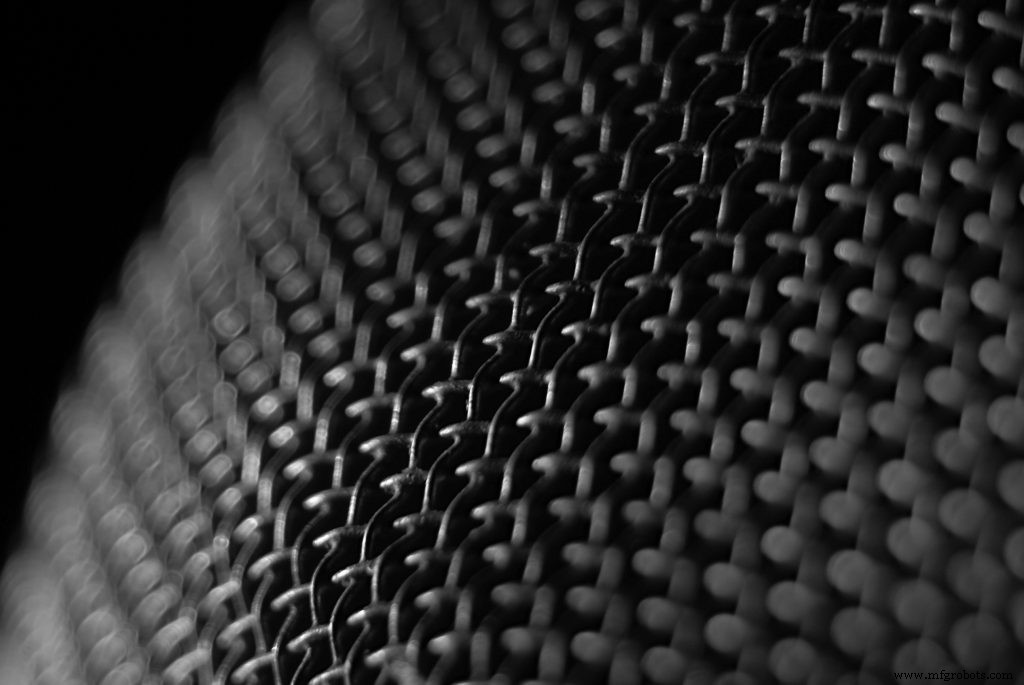
Metal additive manufacturing gives us the freedom and flexibility to produce parts with complex shapes and intricate features. However, as with any technology, it does have its own set of capabilities and limitations. Understanding the basics of design for metal 3D printing is therefore crucial to obtain a successful print.
Below are some of the key considerations to keep in mind when designing for metal 3D printing.
1. Wall Thickness
Choosing the right wall thickness can make the difference between a successful and a failed print.
As a general rule of thumb, it’s recommended to design walls with a minimum wall thickness of 0.4mm.
It’s also important to ensure that the wall thickness of your parts are not too thin or thick, as this can result in deformation during the printing process or cause damage after removal from the build plate.
In the case of thick walls, the mass can be minimised by applying lattice or honeycomb structures, making the overall printing process cheaper and faster.
2. Support structures
While it’s ideal to design a part with the minimum amount of supports necessary, support structures will virtually always be required with metal 3D printing technologies (except for DED).
Supports play two main roles:first, they are used to anchor a metal part to the base plate to draw away heat, which could otherwise cause residual stresses and build failures.
Second, supports are required to successfully print complex features such as holes, angles and overhangs. For these features, angle measures should be noted:overhangs with an angle less than 45° will require supports.
For features located inside a part, such as horizontal holes along the X or Y axis, it’s generally recommended to design angled support structures.
Angled supports can help maintain a solid connection with the printing bed while minimising the amount of contact the supports have with your part’s surface area. This will make post-processing much easier.
Finally, make sure to check that all support structures will be accessible after printing. Any supports that are difficult to reach will be hard to remove cleanly.
3. Overhangs and Self-Supporting Angles
Overhangs are unsupported downward-facing surfaces, and will need to be carefully considered when designing a part.
Large overhangs (typically over 1mm) will require support structures to prevent them from collapsing during the printing process. The maximum length of an unsupported horizontal overhang is typically 0.5mm, and it is important to keep your overhangs below this length.
If your design requires overhangs, you can also design fillets and chamfers under the downfacing surfaces to make the overhang self-supporting.
Angled features can be designed self-supporting. For this, the angle of a feature should not be less than 45°.
4. Part Orientation
Part orientation is another critical consideration with metal 3D printing. Experimenting with the orientation of your part is the best way to minimise the amount of support structures needed.
For example, if you want to make a metal part with hollow tubular features, a horizontal orientation will take up more space, while a vertical or angled orientation will save space and reduce the amount of supports needed.
Part orientation is also important in determining the accuracy and surface roughness of a part. When selecting your part orientation, keep in mind that downward and upward facing surfaces will have different surface roughness (so-called down-skins tend to have inferior surface finish). If you want to produce detailed features with the best accuracy, make sure to orientate these on the upward facing surface of the part.
5. Channels and Holes
Metal additive manufacturing is notable for its ability to produce parts with internal complex channels for improved fluid flow and holes. A general rule of thumb is to not design such features under 0.4mm in powder-bed processes and under 0.2mm in Metal Binder Jetting. Holes and tubes larger than 10mm in diameter will require support structures.
Keep in mind that perfectly round horizontal holes are still a challenge to 3D print. Consider redesigning such shapes into a self-supporting teardrop or diamond shape.
Additionally, if you are designing a hollow part, you need to factor in the design escape holes to ensure the removal of the unmelted powder. A recommended diameter for escape holes is 2-5mm.
Metal 3D printing is emerging as a viable manufacturing technology, as advancements across the spectrum of hardware, materials and software continue to be made.
The technology could help to drive new business models and product development strategies by enabling economic low-volume and on-demand production, innovative design possibilities and, of course, mass customisation.
Of course, it will take some time for companies to become fully confident with the technology. However, an increase in knowledge sharing and education will not only help to further the potential of metal 3D printing, but will also spur a wider adoption of the technology across industries.
Expert Interviews
Digital Alloys CEO Duncan McCallum on Joule Printing and the Future of Metal 3D Printing
HP’s Global Head of Metals on the Impact of HP Metal Jet
ANSYS’ Chief Technologist on Achieving Metal 3D Printing Success with Simulation
Sintavia President Doug Hedges on Achieving Serial Production with Metal 3D Printing
APWORKS CEO Joachim Zettler on Finding the Right Business Case for Metal 3D Printing
SmarTech Analysis’ Scott Dunham on the Future of Metal 3D Printing, Service Bureaus and the AM Materials Market [Part Two]
MELD Manufacturing CEO Nanci Hardwick on Fulfilling the Potential of Metal Additive Manufacturing
3DEO’s President Matt Sand on Taking Metal 3D Printing Into High-Volume Production
VELO3D’s VP of Technology Partnerships on Expanding the Capabilities of Metal 3D Printing
Metal 3D Printing Technologies
Metal 3D Printing:Where are We Today?
All You Need to Know About Metal Binder Jetting
Metal 3D Printing:What is Direct Energy Deposition?
An Introduction to Electron Beam Melting
An Introduction to Wire Arc Additive Manufacturing
Your Guide to the Top DMLS Machines [2018]
Designing for Metal 3D Printing
6 Important Design Considerations for Metal 3D Printing
Making Metal Parts Lighter with Metal 3D Printing
Metal 3D printing Materials
Why Materials are the Key to Metal 3D Printing Success:Expert Interview with voestalpine’s Armin Wiedenegger
3D Printing Precious Metals – a New Approach?
Scalmalloy:The Latest High-Performance Material for Metal 3D Printing
A Quick Guide to 3D Printing Metals
A Guide to 3D Printing With Titanium
Metal 3D Printing Challenges
5 Common Problems Faced with Metal 3D printing – and How You Can Fix Them
Quality Assurance for Metal 3D Printing:Solving 3 Common Challenges
Metal 3D Printing Applications
5 Innovative Use Cases for Metal 3D Printing
How Can 3D Printing Benefit Metal Casting? Here Are 3 Ways
3D 프린팅
3D 프린팅 기술은 식품 관련 응용 분야를 위한 맞춤형 부품을 만드는 수많은 창의적인 방법을 제공합니다. 식품 안전 3D 인쇄라고도 하는 식품 안전 재료에 대한 3D 인쇄 프로세스를 생각할 때 식품 용기에 의해 야기되는 식품 안전 위험에 대해 즉시 생각하기 시작합니다. 따라서 3D 인쇄 부품은 식품 등급이어야 합니다. 즉, 사람이 사용하기에 적합하거나 독성 화학 물질이 식품에 들어가지 않고 식품과 접촉할 수 있어야 합니다. 오랫동안 플라스틱은 식품 취급 자재 및 용기 제조업체에게 최고의 무기임을 입증했습니다. 왜요? 저렴하
클라우드 모니터링 도구는 클라우드 기반 인프라의 상태를 평가하는 데 도움이 됩니다. 이러한 도구는 중요한 클라우드 앱 및 서비스의 성능, 안전 및 가용성을 추적합니다. 이 기사에서는 시장에 나와 있는 상위 30개 클라우드 모니터링 도구를 소개합니다. 사용 사례에 따라 이러한 도구 중 일부는 다른 도구보다 더 적합할 수 있습니다. 올바른 옵션을 찾으면 더 생산적이고 비용 효율적인 클라우드 인프라 구축을 시작할 수 있습니다. 클라우드 모니터링이란 무엇입니까? 클라우드 모니터링은 자동화 및 수동 도구를 사용하여 클라우드 컴퓨팅 아키텍