VHDL Signed vs Unsigned 타입 마스터하기: 실전 인사이트
디지털 설계자는 FPGA와 ASIC 내 정밀 산술에 의존합니다. 핵심 개념은 VHDL에서 signed와 unsigned 데이터 타입의 구분입니다.
두 타입 모두 IEEE 라이브러리의 numeric_std 패키지에 정의됩니다. 많은 설계자가 여전히 std_logic_arith를 쓰지만, 이 패키지는 IEEE 표준이 아니며 프로덕션 설계에 권장되지 않습니다.
VHDL에서 signed 신호는 2의 보수 숫자로 해석돼 양수와 음수 값을 모두 허용합니다. unsigned 신호는 음이 아닌 값만 표현합니다. 내부적으로 FPGA는 선언한 타입과 관계없이 모든 비트 벡터에 2의 보수를 사용합니다.
| 비트 | Unsigned 값 | Signed 값 |
|---|
| 011 | 3 | 3 |
| 010 | 2 | 2 |
| 001 | 1 | 1 |
| 000 | 0 | 0 |
| 111 | 7 | -1 |
| 110 | 6 | -2 |
| 101 | 5 | -3 |
| 100 | 4 | -4 |
처음엔 이 매핑이 직관적이지 않아 보일 수 있지만, 2의 보수를 이해하면 동작이 예측 가능해집니다.
산술 연산의 이진 결과는 피연산자가 signed로 선언됐든 unsigned로 선언됐든 동일합니다. 달라지는 건 그 결과의 해석뿐입니다.
예: 5비트 벡터 두 개 더하기
- Signed: 10001 + 00010 = 10011 (해석: –13)
- Unsigned: 10001 + 00010 = 10011 (해석: 19)
library ieee; use ieee.std_logic_1164.all; use ieee.numeric_std.all; entity signed_unsigned is port ( i_rst_l : in std_logic; i_clk : in std_logic; i_a : in std_logic_vector(4 downto 0); i_b : in std_logic_vector(4 downto 0) ); end signed_unsigned; architecture behave of signed_unsigned is signal rs_SUM_RESULT : signed(4 downto 0) := (others => '0'); signal ru_SUM_RESULT : unsigned(4 downto 0) := (others => '0'); signal rs_SUB_RESULT : signed(4 downto 0) := (others => '0'); signal ru_SUB_RESULT : unsigned(4 downto 0) := (others => '0'); begin p_SUM : process (i_clk, i_rst_l) begin if i_rst_l = '0' then rs_SUM_RESULT <= (others => '0'); ru_SUM_RESULT <= (others => '0'); elsif rising_edge(i_clk) then ru_SUM_RESULT <= unsigned(i_a) + unsigned(i_b); rs_SUM_RESULT <= signed(i_a) + signed(i_b); end if; end process p_SUM; p_SUB : process (i_clk, i_rst_l) begin if i_rst_l = '0' then rs_SUB_RESULT <= (others => '0'); ru_SUB_RESULT <= (others => '0'); elsif rising_edge(i_clk) then ru_SUB_RESULT <= unsigned(i_a) - unsigned(i_b); rs_SUB_RESULT <= signed(i_a) - signed(i_b); end if; end process p_SUB; end behave;
테스트벤치
library ieee; use ieee.std_logic_1164.all; entity example_signed_unsigned_tb is end example_signed_unsigned_tb; architecture behave of example_signed_unsigned_tb is signal r_CLK : std_logic := '0'; signal r_RST_L : std_logic := '0'; signal r_A : natural := 0; signal r_B : natural := 0; signal r_A_SLV : std_logic_vector(4 downto 0) := (others => '0'); signal r_B_SLV : std_logic_vector(4 downto 0) := (others => '0'); constant c_CLK_PERIOD : time := 10 ns; component example_signed_unsigned is port ( i_rst_l : in std_logic; i_clk : in std_logic; i_a : in std_logic_vector(4 downto 0); i_b : in std_logic_vector(4 downto 0) ); end component example_signed_unsigned; begin i_DUT: example_signed_unsigned port map ( i_rst_l => r_RST_L, i_clk => r_CLK, i_a => r_A_SLV, i_b => r_B_SLV ); clk_gen : process is begin r_CLK <= '0' after c_CLK_PERIOD/2, '1' after c_CLK_PERIOD; wait for c_CLK_PERIOD; end process clk_gen; process begin r_RST_L <= '0'; wait for 20 ns; r_RST_L <= '1'; wait for 20 ns; r_A_SLV <= "01001"; r_B_SLV <= "00110"; wait for 20 ns; r_A_SLV <= "10001"; r_B_SLV <= "00110"; wait for 20 ns; r_A_SLV <= "10001"; r_B_SLV <= "00001"; wait for 20 ns; r_A_SLV <= "10001"; r_B_SLV <= "00010"; wait for 20 ns; r_A_SLV <= "11111"; r_B_SLV <= "00001"; wait for 20 ns; r_A_SLV <= "00000"; r_B_SLV <= "00001"; wait for 20 ns; wait; end process; end behave;
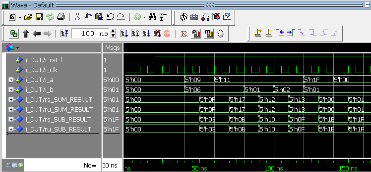
Modelsim 시뮬레이션 파형 – 16진수 값
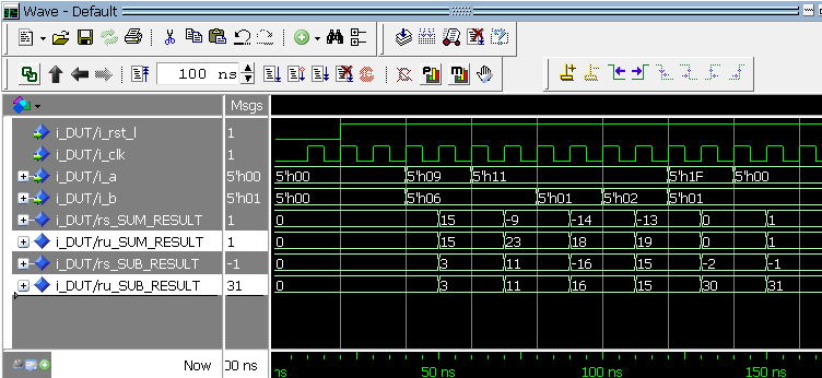
Modelsim 시뮬레이션 파형 – 10진수 값
두 스크린샷은 타입에 관계없이 하부 이진 결과가 동일함을 보여줍니다. 차이는 시뮬레이터가 값을 표시할 때만 발생: 16진수에선 같은 비트 패턴, 10진수에선 signed 결과가 음수로 나타날 수 있습니다. FPGA 로직 설계 시 신중한 타입 처리가 필수적입니다.
이 주제에서 불분명한 부분이 있으면 사이드바 연락처 링크로 이메일 주세요. signed/unsigned 산술 마스터를 기꺼이 도와드립니다.