용량 증가를 포함한 양극 특성 개선은 배터리 성능을 향상시키기 위한 기본 요건 중 하나입니다. 이 논문에서는 합금 성능을 가진 고용량 양극을 소개하고 이러한 양극의 단편화 문제와 주기 수명 동안의 영향에 대해 설명합니다. 그런 다음 조각화 문제를 해결하고 특성을 향상시키는 데 있어 나노 크기로 크기를 줄이는 효과에 대해 논의하고 마지막으로 다양한 형태의 나노 물질을 검토합니다. 본 논문에서는 나노 스케일 현상인 양극에서의 전극 환원에 대해 기술하였다. 이 현상이 합금 양극에 미치는 부정적인 영향을 표현하고 적절한 나노구조를 준비하여 이러한 부정적인 영향을 제거하는 방법에 대해 논의합니다. 또한, 산화티타늄 계열의 양극을 소개하고 이러한 양극의 성능 향상에 대한 Nano의 효과를 표현하고 마지막으로 Nano 특유의 준정전용량 거동을 소개한다. 마지막으로 세 번째 유형의 양극인 교환 양극을 소개하고 그 기능을 표현합니다. 이러한 양극의 가역성에 대한 나노의 효과가 언급되었습니다. 이러한 전극에 대한 나노기술의 장점이 설명됩니다. 이 논문에서 나노기술은 침투 거리를 줄이고 응력을 조절하는 것과 같은 일반적인 효과 외에도 정전용량 준 정전용량, 저장 메커니즘 변경 및 낮은 볼륨 변경.
소개
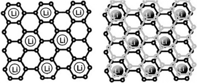
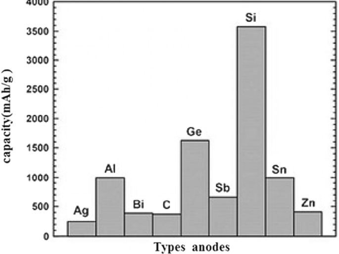
흑연은 층간 거리가 약 35.3Å인 층상 구조의 탄소 재료로, 층 사이에 리튬 원자가 배치되기에 적당한 공간이 있다[1,2,3,4]. 충전하는 동안 리튬 이온은 양극에서 환원되어 리튬 원자로 변환되어 흑연 층 사이에 배치됩니다. 리튬이 도착한 후 판 사이의 거리는 3.5 Å에 이릅니다[5,6,7,8,9,10]. 방전하는 동안 리튬 원자는 리튬 이온으로 산화되어 전해질을 통해 음극으로 운반됩니다. 흑연에 리튬 원자가 삽입되어 있기 때문에(충전 시) 이러한 물질을 삽입 양극이라고 합니다[6,7,8,9,10,11,12,13,14]. 흑연의 그림 1에 따르면 탄소 원자 6개당 최대 1개의 리튬 원자가 저장될 수 있습니다[5]. 흑연은 저장되는 리튬의 양과 직접적인 관련이 있기 때문에 흑연은 리튬 금속 음극보다 용량이 낮지만 앞서 언급한 바와 같이 수지상 성장 문제가 없어 상업용 음극으로 활용되고 있다. 이 기사와 향후 기사에서 양극과 음극은 양극과 음극의 활성 물질을 의미합니다[6,7,8]. 흑연의 낮은 용량으로 인해 고용량의 양극이 필요합니다[15,16,17,18]. 많은 양의 리튬 원자를 저장할 수 있는 음극 그룹은 금속이나 반도체로 만들어진 합금형 음극입니다. 이러한 양극의 기능은 금속 또는 반도체와 합금을 형성하여 리튬 원자를 저장하는 것입니다[19,20,21]. 탄소 원자 6개당 리튬 원자가 하나만 저장되는 흑연에 비해 이러한 유형의 재료에서는 금속 원자당 여러 개의 리튬 원자가 저장될 수 있습니다[9,10,11]. 이러한 양극 중 가장 중요한 것은 실리콘과 안티몬입니다. 실리콘의 경우 용량은 약 4000mAh/g이고 주석의 경우 언급된 용량은 약 350mAh/g의 용량을 갖는 흑연과 비교하여 900mAh/g입니다. 그림 2에 따르면 합금 양극 중에서 실리콘은 부피와 중량 용량이 가장 크고 자연에서 많이 발견되며 전체 전자 산업은 실리콘을 기반으로합니다. 따라서 그림 2에서 볼 수 있듯이 실리콘은 합금 양극 중 가장 중요합니다[12,13,14,15]. 따라서 이 기사에서 대부분의 재료는 실리콘에 관한 것이지만 언급된 원리는 다른 합금 양극에도 일반화할 수 있습니다. 활성 음극재, 이론 용량, 장점 및 연구 결과는 표 1에 나와 있습니다.
<그림>
리튬이 흑연에 어떻게 저장되는지 보여줍니다. 탄소 원자 6개당 리튬 원자 1개가 저장됩니다[12]
<그림>
용량이 있는 양극 유형 [13,14,15]
합금 양극의 문제
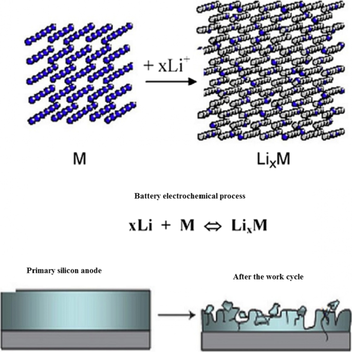
이러한 양극에서 리튬의 저장 및 방출은 그림 3과 같이 초기 부피의 400%까지 도달할 수 있는 큰 부피 변화를 동반합니다. 작업 주기 동안 부피 변화로 인한 응력으로 인해, 활성 물질의 분쇄 현상이 발생한다[7, 10, 39, 40]. 단편화는 활물질 자체 사이, 활물질 전도성 첨가제 사이, 활물질 집전체 사이의 연결을 끊는 원인이 된다[18,19,20]. 이 현상이 발생하면 활성 물질이 전기적으로 절연됩니다. 따라서 산화 반응을 수행하기 위해 전자 이동이 일어나지 않습니다. 따라서 많은 양의 유효 성분이 미사용 상태로 남아 용량에 참여하지 않으며, 이는 궁극적으로 작업 주기 동안 용량의 급격한 저하를 초래한다[21, 41, 42]. 그림 3은 파쇄 현상을 보여줍니다. 안타깝게도 그림 3에는 애노드 전극의 전체 구조가 나와 있지 않습니다. 실제로 기존의 전극에서는 바인더, 탄소 전도성 물질 등과 함께 활물질의 미크론 입자가 사용된다[43,44,45,46]. 위에서 언급한 전자 연결이 끊어지면 끊어집니다. 그림 4는 10미크론 크기의 실리콘 입자에 대한 충전 및 방전 곡선을 보여줍니다. 첫 번째 방전시에도 용량이 800mAh/g에 불과함을 알 수 있습니다(초기 4000충전 대비). 반면 흑연에서는 작업 주기당 용량이 0.03만 감소합니다. 이 양극은 흑연보다 전압이 높습니다(앞서 언급한 공식에 따르면 양극 전압이 높을수록 배터리 전압이 낮음)[10, 21, 39]. 예를 들어, 실리콘은 리튬보다 전압이 0.3~0.4 더 높지만 흑연에서는 전압이 리튬보다 약 0.05V 높지만 실리콘 및 기타 합금 양극은 용량이 너무 커서 전압에 큰 영향을 미치지 않으며, 에너지는 흑연보다 훨씬 높습니다.
<그림>
분쇄 및 전기적 연결 단선 [10]
<그림>
10미크론 실리콘 입자의 충방전 도표 [17]
나노기술 솔루션
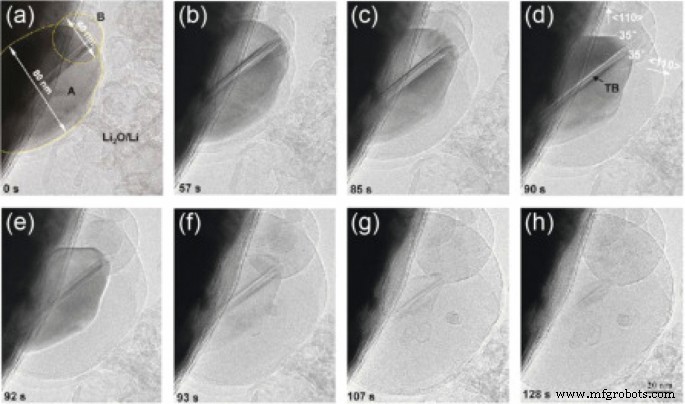
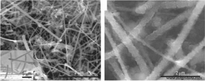
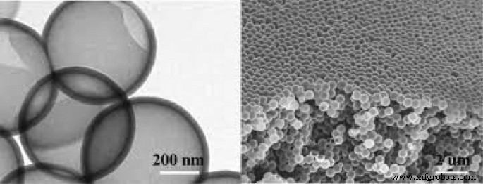
파쇄 현상을 어느 정도 방지할 수 있다면 배터리 성능을 향상시킬 수 있습니다. 연구에 따르면 실리콘의 치수가 나노미터 범위(150nm 미만)에 도달하면 크러싱 현상이 더 이상 발생하지 않습니다[47,48,49,50]. 그림 5는 리튬 이온화 중 실리콘 나노 입자의 TEM 이미지를 보여줍니다. 이 두 입자는 리튬의 유입으로 인해 부피가 변하지만 응력을 받아도 부서지지 않습니다[7, 18, 40]. 이것은 실리콘의 비범한 용량을 사용하기 위해서는 필연적으로 나노 스케일로 가야 함을 보여준다[51,52,53]. 나노입자를 사용하면 단편화 문제는 해결되지만 정상적으로는 전자 공급에 연결되지 않는다. 따라서 연구진은 그림 6(SEM 이미지)과 같이 집전체 위에 수직으로 성장한 실리콘 나노와이어를 처음으로 사용했다. 이러한 방식으로, 큰 응력을 발생시키지 않으면서 듀티 사이클 동안 각 나노와이어의 부피를 변경할 수 있는 나노와이어 사이의 충분한 공간이 있기 때문에 각 나노와이어의 직경도 임계 치수보다 작기 때문에 분쇄 문제를 해결할 수 있다[19 ,20,21,22,30,54,55,56]. 알려진 바와 같이 합금화(리튬의 유입) 후 나노와이어의 폭이 증가하고 측벽이 조직화되어 부피 변화가 크지만 단편화가 발생하지 않았다[57]. 나노와이어에서 전자 이동(집전체와 활성 물질 사이의 통신)은 나노와이어의 길이를 통해 발생합니다. 전자 전달이 잘 되기 때문에 실리콘 활물질의 전체 용량을 사용할 수 있다[31, 32, 35, 36, 37]. 나노와이어는 벌크 재료보다 더 높은 전해질 결합 계절을 갖는다[41,42,43]. 전극-전해질 계면을 통해 산화 반응이 일어나기 때문에 반응 속도도 빨라진다. 반면에, 나노와이어는 이온이 더 먼 거리를 이동해야 하는 벌크 물질에 비해 크기가 작기 때문에 측면 차원을 통한 이온 전달이 용이하다. 빠른 이온 전달과 산화 반응은 전력과 에너지를 증가시킵니다. 이온 전달(때로는 전자 전달에 추가)은 리튬 배터리의 양극과 음극 모두의 잠재적 손실(농도 분극)이기 때문에 이 분극은 침투 거리에 따라 감소합니다. 감소하고 에너지 밀도가 향상됩니다[44,45,46]. 마지막으로 실리콘은 반도체이기 때문에 준금속인 흑연보다 전자 전도성이 낮다[33, 38, 58].
<그림>
a에서 리튬 이온화가 진행되는 동안 실리콘 나노 입자의 TEM 이미지 h까지 각각 리튬 이온화 [19]
<그림>
리튬 동안의 실리콘 나노 입자의 SEM 이미지 [20]
다양한 나노 형태
나노와이어 대신 실리콘 나노튜브를 사용하는 것이 더 효과적인 것으로 나타났습니다. 나노튜브에서는 내벽과 외벽의 양쪽에 체적 변화를 위해 필요한 공간이 제공됩니다[34, 59, 60, 61]. 또한, 나노튜브는 일반적으로 나노와이어보다 얇기 때문에 트랜스미터가 더 좋습니다. 실리콘은 반도체이고 스트레스로 인해 듀티 사이클 동안 비정질이기 때문에 듀티 사이클 동안 전자적으로 잘 전도되지 않기 때문입니다[47, 48, 54]. 결과적으로 전자는 실리콘의 모든 부분에서 잘 흐르지 않습니다. 하이브리드 나노구조는 이 문제를 해결하는 데 사용할 수 있습니다. 예를 들어 코어에 전도성 물질이 포함되어 있거나 그 반대의 경우 전도성 코팅이 있는 실리콘 나노튜브가 있습니다[62,63,64,65,66]. 코팅되지 않은 실리콘 나노와이어와 탄소로 코팅된 실리콘 나노와이어의 두 가지 범주를 비교하면 탄소 코팅된 나노와이어가 상당한 용량을 유지한다는 것을 알 수 있습니다. 또 다른 해결책은 나노복합체 양극을 사용하는 것입니다[49,50,51]. 응력 조절제(완충제)의 역할에서 나노복합체에서 가장 널리 사용되는 재료 중 하나는 탄소입니다. 예를 들어, 탄소 분야의 탄소 나노복합체는 스트레스 문제에 대한 해결책 중 하나입니다. 그림 7은 주석-탄소 나노복합체를 보여줍니다. 주석은 합금 양극과 같은 활성 성분으로 작용합니다. 이 나노복합체의 탄소는 완충제와 전도체 역할을 하며 다양한 탄소 구조 외에도 일부 리튬을 저장할 수 있습니다. 그림 7과 같이 주석 용량은 탄소의 존재로 인해 이론 용량(900mAh/g)보다 작지만 사이클 수명은 양호하다. 최대 1000 작업 주기를 잘 유지합니다[52, 67,68,69,70].
<그림>
탄소의 주석 나노복합체, 어두운 주석 나노입자의 TEM 이미지 및 수명 주기 곡선이 표시되어 있습니다. [54]
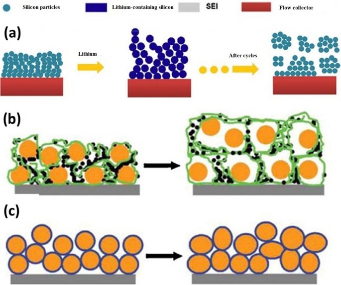
실리콘이 다른 합금 양극보다 훨씬 더 높은 용량을 가지고 있다는 점을 감안할 때 왜 다른 합금 양극이 연구되고 있는지에 대한 질문이 독자의 마음에 떠오를 수 있습니다[71,72,73]. 나노 기술 및 배터리 제품의 전체 컬렉션에 제공되고 일반화될 수 있는 대답은 나노 물질이 다른 방식으로 합성되고 다른 방식으로 다른 형태(모양)로 합성되기 때문입니다[74,75,76,77,78]. 각 합성 방법은 가격, 품질, 안전성, 확장성, 환경 영향 등에 대한 논의와 다릅니다. 예를 들어, 금속은 간단한 방법인 졸-겔 방법으로 준비할 수 없습니다[79,80,81]. 실리콘과 같은 특정 물질의 경우에도 나노섬유와 같은 1차원 나노물질은 대량생산 방식인 전기방사에 의해 나노와이어 형태로 제조될 수 있으며, 이는 고가의 화학기상증착법으로 실험실 테스트의 또 다른 방법이다. [22, 52,53,54]. 나노와이어는 실리콘 에칭으로 제작할 수 있다. 후자의 방법에서는 결정 방향과 도핑을 쉽게 제어할 수 있으며 리튬 저장에 대한 다양한 도펀트 및 결정 방향의 영향을 결정할 수 있습니다[23, 82,83,84,85,86,87,88]. 특정한 모양과 조성을 가진 나노물질이라도 다른 방식으로 사용될 수 있고, 심지어 특정한 방법에서도 다른 반응물은 다른 온도 조건 등으로 사용될 수 있으며, 각각은 가격, 안전성 및 안전성 측면에서 결과가 다를 수 있습니다. 투자가 아닌 상업화의 관건은 위에 열거한 요소들을 고려하여 올바른 생산방법을 찾는 것이므로 전지의 생산과 성능은 떼려야 뗄 수 없는 관계에 있으며 매우 우수하고 적절한 물품 합성법과 관련하여 이용 가능[30, 31 , 56, 57, 89,90,91,92]. 1차원 나노구조체(나노와이어 및 나노튜브) 외에 0차원 나노구조체(나노입자)를 사용하려는 노력이 있어 왔다(좋은 나노입자는 나노와이어보다 합성하기 쉽기 때문). 나노입자의 문제점은 한편으로는 나노입자 자체와 다른 한편으로는 나노입자와 전도성 및 집전 물질 사이의 연결을 쉽게 만드는 것이 불가능하다는 것입니다[32, 35, 36]. 예를 들어, 그림 8a는 충전 중 리튬을 흡수한 후 1차 나노입자(이미지 왼쪽)의 부피가 증가하고 몇 사이클 후에 리튬이 없는 원래 상태로 돌아올 때 전자 연결을 끊는 것을 보여줍니다[3, 24, 93,94,95]. 양극 (또한 음극)을 준비하는 일반적인 방법에서 활성 물질 (여기서는 실리콘)의 분말은 전도성 탄소 (전도도를 향상시키기 위해) 및 PDVF 바인더 (입자의 결합을 위해)와 함께 사용됩니다. 그림 8b에서. 그림 b에 따르면 실리콘 나노입자는 부피가 변하기 때문에 다른 초기 상태로 돌아간 후 나노입자와 탄소 전도성 물질 사이의 전기적 연결이 끊어지고 용량이 감소한다. 그림 c와 같은 방법에서 위의 문제를 해결하기 위해 응력 조절 역할을 하는 비정질 실리콘을 접착제로 사용하여 실리콘 나노 입자를 접착하여 전기적 연결이 더 이상 중단되지 않고 용량이 유지되도록 합니다[25 , 37, 38, 96, 97]. 또 다른 방법으로, 변조 및 전자 전도 역할을 모두 갖는 폴리아닐린 전도성 고분자 분야의 나노 입자가 1600mAh/g의 용량을 유지하면서 1000의 양호한 사이클 수명을 갖는 것으로 제조 및 관찰되었습니다. 이에 비해 PVDF 바인더 방법은 100번의 작업 주기에서 용량의 50% 이상을 잃습니다. 이 문제를 해결하는 또 다른 방법은 속이 빈 나노구조입니다. 이 방법에서는 중공 체적을 통해 리튬이 출입할 때 필요한 빈 공간을 제공합니다[26, 27, 33, 58, 59]. 유한요소법은 동일한 체적에서 중공 구조가 작업 주기 동안 응력을 덜 받기 때문에 파쇄 현상에 대한 저항성이 더 우수함을 보여줍니다(그림 9).
<그림>
아 집전체와 나노입자의 전기적 관계가 어떻게 깨지는지 보여줍니다. b 다른 유형의 분리를 보여줍니다. 주황색의 실리콘 나노 입자와 검은 색의 탄소 및 PDVF 폴리머 사슬은 녹색으로 표시됩니다. ㄷ 비정질 실리콘 접착제를 사용하여 변형 후에도 나노입자를 결합합니다[47].
<그림>
부피 변화 문제를 해결하기 위한 속이 빈 나노 입자 [48]
양극의 전해질 분해
우리가 알고 있듯이 모든 물질은 전위 범위에서 안정적이며 이 범위 내에서 다소 환원 또는 산화 과정을 거칩니다[28, 98, 99]. 이것이 우리가 물을 분해(전기분해)하여 수소와 산소를 생성할 수 있는 이유입니다. 이 전지는 전해질 전지라고 하는 갈바니 전지(배터리)의 반대입니다. 이 전지에서는 배터리와 달리 열역학적으로 바람직하지 않은 반응을 일으키기 위해 에너지를 제공합니다[60].
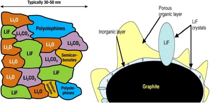
배터리를 충전할 때 물이 분해되는 것처럼 충전기를 통해 배터리에 에너지를 공급하여 배터리에서 발생한 반응을 역전시켜 배터리를 방전 전 상태로 되돌립니다[100,101,102,103,104]. 리튬 이온 배터리(예:물 전기분해)에 사용되는 유기 전해질은 충전기의 에너지 결과로 변경됩니다. 앞서 언급한 바와 같이 리튬 이온 배터리에서는 음극(흑연 양극)에서 충전 중에 리튬 이온 환원이 발생합니다. 전해질 환원 경향이 리튬 이온보다 열역학적으로 높기 때문에 리튬 이온 환원 대신 전해질 환원이 이루어집니다. 이로 인해 흑연 표면에 단단한 층이 형성됩니다. 이 고체층을 SEI(고체 전해질 계면)라고 합니다. 이 층의 구성은 복잡하고 여러 화학 물질의 혼합물입니다. 그림 10은 이 레이어의 개략도를 보여줍니다. 그림에서 알 수 있듯이이 물질의 구성에는 리튬 이온과 탄소가 포함되어 있습니다. 따라서 이 층의 형성은 리튬의 감소를 동반하여 첫 번째 충전의 용량을 감소시킵니다[34, 61]. 이 두께의 층은 그림 10과 같이 나노미터 범위입니다. SEI 층 자체의 형성은 전해질 분자가 물리적 장벽으로 흑연 양극 표면에 도달하는 것을 방지하기 때문에 전해질 환원 반응의 지속을 제한합니다. 사실, 그것은 운동 억제제로 작용합니다(산소가 하부 알루미늄에 도달하는 것을 방지하고 나머지 알루미늄이 산화되는 것을 방지하는 산화알루미늄의 수동층과 같은). 한편, 전자 절연체이기 때문에 전자가 전해질에 도달하는 것을 방지하기도 한다[62,63,64,65]. 따라서 전자는 전해질 분자에 도달할 수 없고 전해질 분자는 양극에서 전자 쪽으로 이동할 수 없으며 둘 다 전해질을 재생하고 자체 제한 반응을 일으키게 합니다. 다행히도 이 층은 리튬 이온을 투과할 수 있으며 리튬 이온은 이를 통해 양극 표면으로 통과하여 전자를 포획하고 재생성할 수 있습니다[105,106,107,108]. 이 층은 양극에 도달하는 리튬 이온의 침투 거리를 증가시켜 배터리 전력을 감소시킵니다[109,110,111].
<그림>
이 층의 SEI 형성 및 구성 개략도 [66]
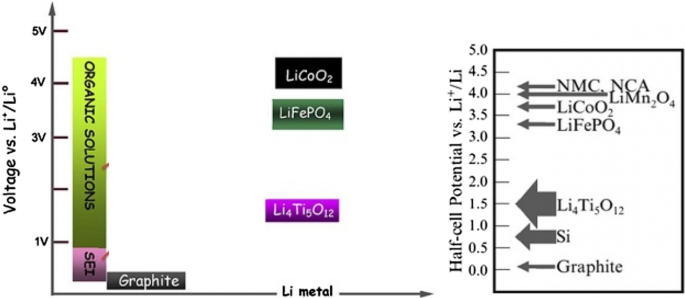
그림 11은 양극과 음극의 전위에 대한 전해질 안정성 범위를 보여줍니다. 음극이 전해질 안정성 범위보다 높은 전위를 가지면 음극에서 그리고 충전 중에 전해질이 산화되고, 또한 양극이 안정 범위보다 낮은 전위를 가지면 양극에서 그리고 전해질 충전 중에 재생됩니다. 다행스럽게도 그림 11과 같이 기존의 음극은 전해질 불안정성의 문제가 없으나 흑연과 실리콘 음극은 불안정성이 있어 SEI가 형성된다[66,67,68].
<그림>
공통 양극 및 음극의 전압과 전해질 안정성 전위 범위 및 SEI 형성 전위 범위를 보여줍니다[67]
실리콘의 SEI 문제
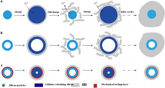
일반적으로 리튬 금속에 비해 1볼트 미만의 음극은 전해질이 불안정하여 SEI가 형성된다. 따라서 SEI는 리튬보다 0.3~0.4 높은 전위를 갖는 실리콘 음극에 형성된다[112,113,114,115]. 불행히도 실리콘은 부피가 변하고 분해되기 때문에 새로운 수준의 실리콘이 전해질에 노출되어 전자가 전해질에 도달하고 이러한 새로운 표면에 새로운 SEI가 형성됩니다. 결과적으로 작업 주기 동안 용량이 지속적으로 감소합니다. 테스트가 종종 리튬 금속에 대해 수행되기 때문에 리튬에 대한 전압이 모든 배터리 제품에서 측정되기 때문에 이것을 말할 필요가 있습니다[69]. 실리콘 나노물질은 화학적 활성이 높기 때문에 SEI 형성에 더욱 취약합니다. 나노 물질의 경우 분해되지 않고 부피가 변하는 것이 사실입니다. 그림 12에 따르면 이러한 볼륨 변화로 인해 SEI가 지속적으로 증가하고 용량 및 전력 감소 등 SEI 성장의 단점이 있음을 알 수 있습니다. 섹션의 그림 13은 나노 물질에서 SEI 성장의 이유를 더 잘 보여줍니다. 그림의 왼쪽과 같이 초기 상태의 리튬이 없는 나노와이어(또는 나노입자 등)의 단면을 가지고 있다면 충전 시 실리콘이 리튬을 함유하고 있기 때문에 그 부피가 증가하고 전해질로 인해 불안정성과 동시에 나노와이어에 SEI 층이 형성된다[116,117,118,119]. 이제 방전 중에 리튬이 나오고 SEI가 수축하지 않는 동안 입자가 수축합니다. 이로 인해 SEI가 응력 하에서 무너지게 됩니다(또는 리튬 이온화 하에서 실리콘 확대의 두 번째 단계에서도 SEI와 입자 사이의 정확한 경계가 정확히 일치하지 않기 때문에 응력이 발생하고 SEI가 무너짐). 따라서 재충전(리튬 이온화) 시 새로운 SEI 층이 다시 형성됩니다. 이 주기의 반복은 지속적인 SEI 성장으로 이어지며 성장에 문제가 있는 반면 흑연에서는 약간의 부피 변화 없이 SEI가 성장하지 않습니다. SEI 및 실리콘에 대해 언급한 내용은 다른 합금 양극에도 적용된다는 점에 유의해야 합니다[70, 120,121,122,123]. 섹션 b에서 볼 수 있듯이 이 문제는 실리콘 나노튜브에도 존재하지만, 처음부터 실리콘이 전해질과 접촉하여 전해질 부근에서 부피가 변하는 것을 어떻게든 막을 수 있다면 이 문제는 해결될 것입니다.
<그림>
SEI 레이어 성장 방법 [19]
<그림>
다양한 조건에서 SEI의 성장을 보여줍니다[20]
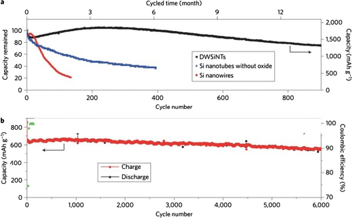
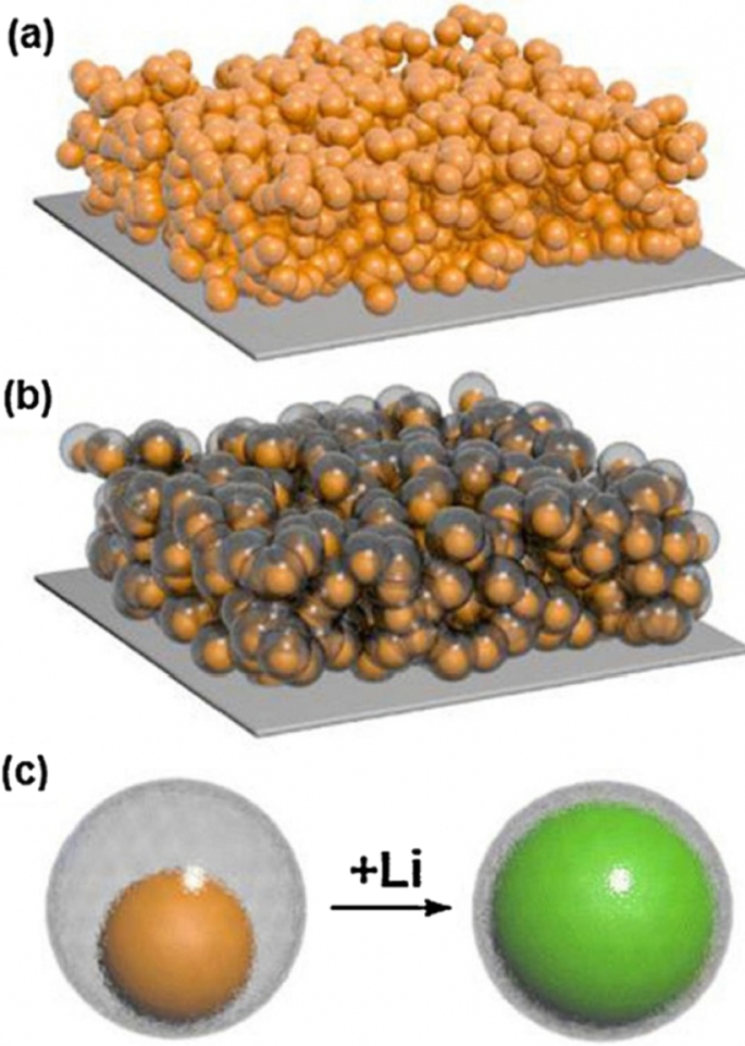
Wu et al. [18]은 그림 13c와 같이 기계적 잠금 레이어를 사용했습니다. 실리콘 산화물로 이루어진 이 층은 기계적 강도로 인해 나노튜브의 외부 부피 변화를 방지합니다. 따라서 체적 변화 없이 안정적인 SEI가 형성됩니다(그라파이트와 같은 안정적인 SEI 층). 이 산화물층은 리튬이온의 전도체이므로 반응에 문제를 일으키지 않는다. 부피 변화에 필요한 공간도 나노튜브의 내벽을 통해 제공된다. 따라서 분쇄의 문제가 없습니다. 전해질이 나노튜브 속으로 침투하지 않는다는 연구 결과가 나왔기 때문에 전해질과 나노튜브 내벽 사이에는 접촉이 없다. 이러한 모든 장점으로 인해 긴 수명과 우수한 출력을 제공합니다. 그림 14(DWSiNT와 함께 이 그림에 표시됨)는 이 샘플의 심방전 주기의 일부를 보여줍니다. 심방전에서는 사이클 수명이 항상 더 빨리 단축됩니다. 그러나 900 사이클 후에도 준비된 샘플은 여전히 좋은 용량을 갖지만 일반 나노튜브 및 나노와이어 샘플은 용량을 빠르게 잃는 것으로 관찰됩니다. 방전됨) 플롯된 샘플의 경우 최대 6000개 개방 주기에서도 이 비교적 높은 C 속도 후에도 용량이 용량을 유지함을 보여줍니다. 다른 예[19]에서는 그림 15c와 같이 탄소 코팅이 탄소 코팅 내부에 실리콘 나노 입자와 함께 사용되는 코어-쉘 구조가 준비됩니다. 탄소 코팅의 두께는 10nm 범위이며 100nm 실리콘 입자를 포함합니다. 탄소 쉘은 그림 c와 같이 실리콘 나노 입자의 부피를 쉽게 변경할 수 있는 충분한 공간을 제공합니다. 한편, 실리콘 나노입자는 한 점에서 탄소 쉘에 부착되어 있어 그 안에서 전자와 이온 전이가 일어나는데, 탄소는 흑연과 같이 실리콘이 아닌 전해질 부근에 있기 때문에 부서지지 않고 안정적인 SEI가 형성된다. 실리콘의 부피 변화는 탄소로, 탄소에서 SEI로 전달되지 않기 때문에 그림 12의 그림과 유사하게 긴 사이클 수명을 갖는다. 일반적으로 실리콘 나노입자를 사용한다면 SEI 문제 외에 이전 글과 그림에서 보았듯이 실리콘 나노입자 사이에 부피를 변화시킬 수 있는 빈 공간이 없기 때문에 입자 사이에 응력이 존재하는 것을 알 수 있다. 부피가 변하지만 이 속이 빈 구조를 사용할 때(그림 b) 더 이상 입자 사이에 응력이 없습니다.
<사진>
아 산화 코팅된 검정, 파랑 및 빨강의 주기 수명 비교, b 각각 무산화물 및 비산화물 나노튜브 [21]
<그림>
아 실리콘 나노 입자로 만든 전극의 디스플레이. ㄴ 탄소 코팅과 중공 구조의 실리콘 나노 입자로 만든 전극 디스플레이. ㄷb에 사용된 중공 쉘의 구조 , 실리콘은 중공 탄소 내부에 있으며 리튬 이온화 과정에서 부피 변화가 관찰됨 [10]
이 양극은 그림 12의 샘플과 비교하여 SEI 문제 외에도 다른 장점이 있습니다. 나노튜브에 비해 나노입자 합성의 장점 중 하나, 더 중요하게는 나노와이어에 비해 나노입자를 사용하는 것이 슬러리 방법과 잘 호환됩니다. 이는 배터리에서 전극을 제조하는 기존의 방법입니다.
LTO 양극 소개
지금까지 흑연 양극과 합금(실리콘) 양극의 두 가지 유형에 대해 이야기했습니다. 매우 인기 있는 또 다른 양극은 Li4Ti5O12 화합물이 포함된 양극으로, 줄여서 LTO라고 합니다. 이 양극은 삽입 흑연과 같다[29, 124,125,126,127]. 그림 16은 이러한 유형의 양극의 구조와 반응을 보여줍니다. LTO 양극의 용량은 175mAh/g으로 제한되어 있습니다(300개의 흑연 및 4000개의 실리콘과 비교). 이 양극의 전압도 그림 17에 따라 리튬 금속에 비해 약 1.5V입니다(음극 전압이 낮을수록 배터리 전압이 높음). This high voltage and low capacity both make this anode have very low energy, but it is still one step ahead of silicon in commercial terms. One of the most important features of this anode is the safety issue, because in electric vehicles there are unpredictable conditions, and the other is the long cycle life, and finally its power [72, 73, 128,129,130].
Shows the structure and entry of lithium ion in LTO along with its reaction [74]
a Displays the nanostructure discussed including Nano primary nanoparticles, b charge–discharge curve for ordinary micro particles, and c for a-shaped particles [74]
Due to the fact that the voltage of this anode is high, it is in the range of electrolyte stability according to Fig. 17, so SEI is not formed. On the other hand, as shown in Fig. 17, there is enough space for lithium ions in this composition and it does not change volume, while even in graphite, some volume change is seen due to the entry and exit of lithium. Unlike the previous two anodes, lithium ions (not lithium atoms) are stored in this anode, and the oxidation reaction is due to the conversion of titanium to 3-valent titanium, not to a change in lithium capacity [28, 74, 75, 131].
This battery, because it has neither SEI nor volume change, maintains the capacity well and has a very long cycle life (more than graphite) of about 20,000 cycles. Because it is an oxide compound and is very safe due to the lack of volume change. Because it does not have SEI, its power is not bad either, only its lithium ion diffusion coefficient is low and its electron conductivity is poor. To solve this problem, they provide LTO nanostructures. Because this anode did not have SEI from the beginning, when it becomes Nano, it does not have the problem of forming more SEI, so it does not have more nanomaterial activity [32, 35,36,37].
It has been observed that nanoparticles cause the LTO anode to charge and discharge within 5 min (12C). To prepare the nanostructure, first titanium oxide nanostructure is prepared and then reacted with a lithium source material when heated. This is also an advantage of LTO, as the preparation of TiO2 nanostructures is very popular. Due to the problem of low volumetric density and agglomeration of nanomaterials, micron secondary particles made from nanoscale primary particles are more useful [33, 38, 58, 59].
Figure 17 shows part an of this nanostructure. As can be seen, from the controlled community of smaller particles measuring 10 nm, larger micron particles are formed. According to the comparison of parts b and c in Fig. 17, it is quite clear that this nanostructure is superior to ordinary micron particles, because it has less capacity and potential (especially in discharge). From this nanostructured anode, a battery is made and it is observed that this battery is superior to the battery with graphite anode both in terms of cycle life and power, which is not given due to the brevity of these curves [75]. The benefits of Nano-LTO have been well documented in many articles, but what makes it stand out is an important discussion of proper engineering of the structure, proper synthesis method, and how to use the conductive material to improve conductivity for further improvement. The future will be talked about. In addition, it is not disputed that nanotechnology is useful for LTO, but many of the phenomena that occur at the nanoscale for LTO are discussed so that some are not fully understood.
Another phenomenon that occurs at the nanoscale is the change in charge–discharge curves for the LTO anode. This anode provides a constant voltage over a wide range of capacities (red box in Fig. 18). When LTO ions are Nano, the constant voltage range decreases until after a critical limit (in the range of a few nanometers) there is no longer a constant voltage range [76].
Shows the linear curve range at the LTO anode in the charge–discharge axis [75]
One of the things that happens on the surface is the insertion of more lithium ions into the surface layers. In the surface after insertion, we reach the formula Li8.5 Ti5 O12 , which is 1.5 mol more than the inner layers with the formula Li7 Ti5 O1 , but in the micron material, because the percentage of surface is not high, it shows its effect, but for Nano, because the amount of surface is large, the effects are large. There are several on the charge–discharge curve.
TiO2 Anode
There is also a TiO2 anode from the LTO family. These anodes are easier to synthesize, and because they do not want to react with heat-induced lithium ion precursors, they do not have heat-induced problems such as nanomaterial growth. In addition, according to the chemical formula, titanium oxide has a capacity of twice the amount of 335 mAh/g (LTO). The general response of these anodes is \({\text{TiO}}_{2} + x{\text{Li}}^{ + } + xe^{ - } \leftrightarrow {\text{Li}}_{x} {\text{TiO}}_{2} .\)
TiO2 has four types of phases or crystallographic structures (different atomic arrangements) known as Brocket, Anastasi, Rutile, and (TiO2 (B). The Brocket phase does not matter to the battery. Antara and rutile, which are very popular phases, are important as anodes. Phase (TiO2 (B) performs better than others due to its atomic open space and suitable channel for ion transport, and is the most important [75, 76, 132,133,134,135,136].
If we consider the theoretical capacity based on the chemical formula (one mole of lithium ion per mole of TiO2 ), it is equal to the above value, but based on the phase and position that can be placed according to the lithium ion crystal lattice, different theoretical capacities for different phases have been reported; for example, for anisate, according to network sites, the half-capacity is high, 0.5 mol of lithium ion per mole of TiO2 , 167 mAh/g.
Because all of these phases have poor ionic conductivity, the nanoscale is very effective in increasing both power and capacity. What is interesting is that the nanostructured capacity of Anastasi is more than the theoretical capacity based on the position of the network, but it is definitely less than the theoretical capacity of Formula 334 in all phases. Rutile in micron mode can only store 0.1 mol of lithium ion per grid unit. In rutile, lithium locations are located throughout the network, but the diffusion coefficient in the direction of the c -axis is one order of magnitude greater than that of the ab plate [137,138,139,140,141]. The lithium atom penetrates well in the direction of the c -axis, but must be diffused throughout the space by penetrating the ab plane, and because the diffusion velocity is low in the ab plane, lithium ions accumulate in the c channel, causing a charge repulsive force. Lithium ion positive is generated. This repulsive force prevents more ions from entering the network. As an interesting result of the Nano effect, it has been shown that when the dimensions of rutile become Nano, the capacity reaches 0.8 mol of lithium ion, which has a reversible capacity during different cycles, which reduces the penetration distance and the effect of its quadratic power [142,143,144,145,146]. There is no repulsive force. Figure 19 shows the charge and discharge curves and the cycle life for rutile bulk (micron), commercial rutile micro particles, and rutile nanowires. As can be seen, nanowires show good cyclic longevity and capacity. The shape also confirms that the shape of the nanomaterials also affects the performance of the anode. Morphology such as nanoparticles, nanowires, etc. differ in both capacity and life cycle and power, but the type of morphology alone is not decisive but the geometry of the structure that determines the performance (in the future about the geometry of the structure for all active materials for example, nanowires connected to a current collector, nanowires mixed with graphene, and insulated nanowires each present different results. In addition, there are test conditions and C rate and many other factors [77]. Phase (TiO2 (B), which is newer than other phases, offers the best power and capacity due to its suitable channels for lithium ion transport [147,148,149,150,151]. Figure 20 shows the structure of the penetration site. The capacitance can be significantly increased. This phase offers the best power and capacity among all titanium anodes including LTO, so that by Nano partying it in just 4.5 s, the anode can be charged or discharged with a capacity of 73% of theory. We do not have volume change in this anode either.
a Charge–discharge curve for the first time, b cycle life [77].
Showing the atomic structure of the phase (TiO2 (B) [77]
Quasi-capacitive Capacity
So far, it has been discussed about the storage capacity of lithium ions in the form of a degree in the nuclear network, and this capacity is improved in the nanoscale due to the reduction of the penetration distance, and so on [152,153,154,155]. But one of the interesting phenomena that occurs for these anodes at the nanoscale is the storage of lithium ions at the surface due to the large surface-to-volume ratio. This type of storage is different from the insert and alloy capacity mentioned so far. This type of storage is very fast because it does not require penetration, and also because it does not create stress and the like, it has the best cycle life and power compared to other lithium storage methods [156,157,158]. Of course, this type of capacity generates less energy. This capacity is discussed in more detail in the topic of super capacitors. The Fig. 21 shows a comparison between the storage capacity of LTO capacity in three different Nano dimensions [78]. According to Fig. 21 in small Nano dimensions, this capacity is significant and decreases significantly with increasing dimensions. It should be noted that capacitive capacitance is not only related to titanium oxide compounds but is also present in many other active substances that are mentioned when introducing them.
Demonstration of input and super capacitor capacities in titanium oxide [78]
Introduction of Exchange Anodes
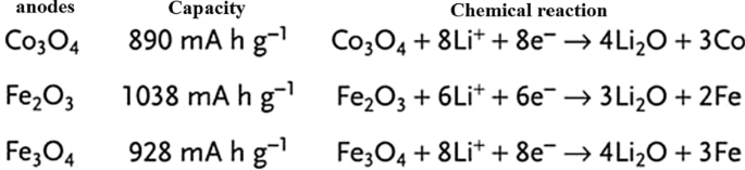
So far, we have talked about two types of insert electrodes and alloys. The third type of electrode operation is based on a conversion reaction. Figure 22 shows the mechanism and reaction of this type of electrode. In this form, M (or Me) is an intermediate element that is oxidized, and X is an anion such as oxygen, sulfur, and the like [159,160,161]. The advantage of these anodes is that for every MxXy unit, n lithium ions (n more than one) are involved in the reaction, whereas in the graphite insert anodes we see one lithium ion for every 6 carbon atoms stored in titanium compounds. A maximum of one lithium ion is stored per TiO2 formula unit. But in the exchange anode, for example, for CoO and FeO, the value of n is equal to 2, and in Co3 O4 , the value of n is equal to 8. Figure 23 shows a number of exchangeable oxide anodes with their reaction and capacity [22, 30, 55].
Shows the structure and entry of lithium ion with its reaction [22]
Shows the reaction and capacity of a number of conversion oxide anodes [30, 55]
Exchange Anode Problems
Exchange anodes are very similar to alloy anodes, as alloys have problems with volume change, fragmentation, and SEI formation. In these anodes the ionic and electron conduction is low, and in addition the exchange rate is slow. This low speed leads to high potential during charging and discharging. At these potentials, there is a large difference between the charging and discharging voltages, called hysteresis, which is shown in Fig. 24 with a red arrow. This figure shows that in the first stage of lithium extraction, the anode behavior is significantly different from the next stage of charge and discharge. The hysteresis in this type of anode is up to one volt, while in the graphite and LTO anode it is about 0.2 V. This hysteresis is mostly due to activation polarization [78, 79].
Show charge–discharge curves of exchange anodes [79]
Nano Sizing Effects
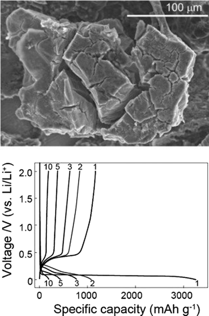
Figure 25 shows the lithium ionization behavior (in the test mode, against lithium metal) for anodes made of fine nanoparticles (20 nm) and micro-nanoparticles (500 nm) of iron oxide (SEM) images of these particles in Fig. 26. Available it can be seen that the capacity of the Nano anode is slightly higher. More importantly, it can be seen that the charge–discharge behavior of these two anodes is very different from each other, which is examined in Fig. 26. Figure 26 shows the charge–discharge curves in different cycles as well as the cycle life for the same samples in Fig. 25 to determine the reason for the difference in charge–discharge curves in Fig. 25. Note that instead of capacity, lithium that enters and leaves (which, according to the arguments, represents capacity) is used. In the charge–discharge curves of Fig. 26, lithium ionization continued only up to 1 mol because its purpose was to investigate the behavior in this range of lithium ions. As can be seen, the effective surface mass for the material is only 2 m
2
/g while for the Nano it has an effective surface area of 60 m
2
/g, which indicates how much higher the effective surface area is at the Nano. The difference between Nano and Nano performance is also quite clear. As shown in Fig. 26, the amount of reversible lithium (which can be removed during charging) for Nano is much higher than the corresponding amount for bulk. This shows that the capacity that can be recovered after the initial charge is much better in Nano than in micro. Also, according to the same figure, in the next consecutive charge-discharges, the amount of lithium entering and leaving is less than 0.25 (from 0.75 to 1), while for Nano, the amount of lithium entering and leaving is more than 0.5 (the amount of lithium ion). In the composition it has changed from the range of less than 0.5 ions to 1 ion), according to this, the capacity offered in Nano is much more than bulk. In the micron-sized anode of Fe2 O3 (hematite), before the exchange reaction begins, about 0.1 mol of lithium ion per mole of oxide compound can be stored in the lattice, but above this critical limit, the exchange reaction takes place; on the other hand, when we increase the dimensions of iron oxide particles to 20 nm, the amount of lithium stored in degrees reaches 1 mol, which causes a volume change of only about 1%. Of course, about 0.5 mol is reversible (Fig. 25). In fact, the type of storage mechanism (input, exchange, etc.) changes and the type of mechanism affects the shape of the charge–discharge curve. The above paragraph indicates that when the oxide dimensions enter the Nano field, the storage mechanism is also affected. So far it has been said that Nano makes volume change easier without failure, but here it can be seen that even Nano has reduced the amount of volume change from a few percent for the exchange reaction to one percent for a degree reaction. The reason for this change is the storage mechanism for iron oxide due to thermodynamic problems. The opposite happens for the Co3 O4 anode because it is kinetic and is related to the current density (the current density is obtained by dividing the current by the surface); when the current is constant, in the Nano-dimensions, because the surface is higher, the current density decreases and the Co3 O4 anode shows exchange behavior, but in the micro, due to the high current density, the anode shows the insertion behavior [76,77,78,79].
Demonstration of lithium ionization for n -Fe2 O3 and micro-M-Fe2 O3 [80]
Display of SEM images, charge–discharge curves and cycle life for Nano-iron oxide and bulk [80]
It can be seen from Fig. 26 that at the nanoscale, the cycle life is also much better than bulk. The reason for the improvement of these expressed properties is the ease of volume change and release of stress, ionic and electronic transitions are easier due to the reduction of the penetration distance, which was expressed in this series of articles. Due to high hysteresis, less attention has been paid to compounds with hysteresis [22, 51,52,53,54, 80].
Nanomaterials in Batteries
Nanomaterials have been widely applied in the life sciences, information technology, the environment, and other related fields. Recently, nanostructured materials have also attracted attention for application in energy storage devices, especially for those with high charge/discharge current rates such as lithium ion batteries. The development of next-generation energy storage devices with high power and high energy density is key to the success of electric and hybrid electric vehicles (EVs and HEVs, respectively), which are expected to at least partially replace conventional vehicles and help solve the problems of air pollution and climate change. These energy storage technologies will rely on innovative materials science, i.e. developing electrode materials capable of being charged and discharged at high current rates. Generally, the potential advantages of nanostructured active electrode materials can be summarized as follows:new reactions can be used that are not possible with bulk materials; a larger electrode/electrolyte contact area, leading to higher charge/discharge rates; short path lengths for both electronic and Li ion transport (permitting operation even with low electronic or low Li ion conductivity, or at higher power); etc. Here, we review some recent experimental results that show the advantages of nanostructured active electrode materials [147]. Table 2 summarizes the nanotechnologies that are used to produce nanomaterials, such as mechanical ball milling, chemical vapour deposition, the template method, electrochemical deposition, hydrothermal reaction, dehydration, sintering, pulsed laser deposition, ultrasound, sol–gel synthesis, and micro emulsion.
The first group of applications of nanotechnology in batteries is itself divided into two categories:the first group nanoscale the active substance in the electrode, the second group use nanotechnology to improve the performance of electrodes (cathode or anode) by adding nanomaterials other than the active substance, or the use of Nano coatings. For example, Nano-dimensional additives such as Nano carbons, graphene, carbon nanotubes, etc. have better electron conduction, or the use of Nano-thick coatings on the active material to prevent unwanted reactions with the electrolyte, stress modulation, provide stability and …. 그것을 위해. For example, for a LiFePO4 cathode, the amount of electron conductivity is poor. Conductivity is improved by using a conductive carbon coating on its particles or by using a conductive carbon material as an additive, A Nano-thick coating of oxide is used [83, 94, 172,173,174,175,176,177]. For example, for a LiFePO4 cathode, the amount of electron conduction is poor, Conductivity is improved by using a conductive carbon coating on its particles or by using a conductive carbon material as an additive, or the LiCoO2 cathode is unstable at high currents in the vicinity of the electrolyte, using a Nano-thick oxide coating to stabilize it [162, 163, 178, 179]. If we want to illustrate the field of nanotechnology in this category with an example, in the same LiFePO4 cathode it has been shown that carbon coating increases conductivity and consequently power, capacity, etc., but one of the areas of research is how to create this coating. Be cheap, effective, etc.; therefore, research in the field of synthesis methods is very important. On the other hand, how to add the same coating and additives to be more effective, so the engineering and architecture of nanostructures is one of the important areas of research and the preparation of these engineered structures is also an interesting issue. Consider Fig. 27 to clarify the matter. This figure shows two types of Nano-engineered structures for the LiFePO4 cathode that use carbon nanotubes to improve conductivity. In addition to differences in performance, each of these structures has a different synthesis method, which indicates the importance of synthesis.
a , b With carbon nanotube core and LiFePO4 wall, and Figure c LiFePO4 nanoparticles attached to carbon nanotube [3, 93]
Silicon has attracted tremendous attentions as one of the most promising candidates for the next-generation Li-ion batteries (LIBs). Compared to the traditional graphite anode, it has many obvious advantages such as large capacity, high abundance and environmental friendliness [1,2,3,4]. Unfortunately, due to the huge volume expansion (~ 300%) in lithiation, silicon particles are pulverized and solid electrolyte interphase (SEI) layers formed on their surface are unstable. Therefore, the long-term cycling stability of silicon anode is poor [5,6,7,8]. Moreover, the low intrinsic conductivity of Si causes unsatisfying rate-capability [9,10,11,12]. Thus, a large amount of Si/metal (e.g., Ag, Cu, Al, Sn) composites have been developed to solve the low conductivity [13,14,15,16]. However, the large volume expansion cannot be relieved effectively. On the other hand, carbon Nano layers are coated on the electrode materials to increase their conductivity, enhance their mechanical strength and provide them stable interfaces with electrolyte. Therefore, various conformal carbon layer coated silicon (Si@C) nanostructures are developed. For example, Si@C with core–shell structure are formed by pyrolyzing various precursors (e.g., pitch, glucose) to coat carbon layers on the pre-prepared silicon nanoparticles [17,18,19,20,21].
Cui et al. designed a hierarchical pomegranate-structured Si@C composite and a nonfilling carbon-coated porous silicon micro particle via the pyrolysis of resorcinol–formaldehyde resin (RF), respectively [23, 82]. And Yu et al. prepared double carbon shells coated Si nanoparticles via chemical vapor deposition (CVD), with acetylene as carbon source [24]. All these designs provide sufficient voids to allow large volume changes of Si during the lithiation/delithiation. However, most of Si@C composites were prepared in separate steps by either pre-coating or post coating carbon on silicon nanomaterials. It led to a complicated preparation strategy.
Continued interest in high performance lithium-ion batteries has driven the development of new electrode materials and their synthesis techniques, often targeting scalable production of high quality nanoceramics (< 100 nm in diameter), which may offer performance improvements. However, there are a number of hurdles, which need to be overcome to move away from current batch synthesis methods that offer poor reproducibility or lack of control over crystallite attributes, particularly at larger scale syntheses. Continuous hydrothermal flow synthesis (CHFS) processes are a promising route for the direct and controlled manufacture of Li-ion battery electrode nanoceramics. Such processes use superheated water and metal salt mixtures as reagents. In a typical CHFS reaction, a feed of supercritical water (above the critical point of water (TC = 374 °C and Pc = 22.1 MPa), is rapidly mixed in an engineered mixer [1] with a metal salt/base aqueous precursor feed (at ambient temperature and the same pressure), resulting in rapid formation of the corresponding nanocrystallite oxide in the water. This nucleation dominated reaction occurs as a result of the metal salts being supersaturated upon mixing with sc-water and also instantly being hydrolysed and dehydrated under these exotic reaction conditions. The nascent nanocrystallite metal oxide stream in water is then cooled in process and then can be constantly collected from the exit of the CHFS process as an aqueous nanoparticle slurry at ambient temperature. The cleaned crystallites (e.g. via dialysis) can be obtained as a wet solid and then freeze-dried to retain maximum surface area and reduce agglomeration. Compared to batch hydrothermal syntheses, CHFS type processes typically produce very small nanoparticles (< 10 nm) with a narrow size distribution [2,3,4]. Additionally, CHFS processes are highly scalable (> 1 kg per hour in the lab of the UCL authors [5]) and can be used to make high quality nanoparticles at scale, with little or no significant variation between those made on the smaller CHFS laboratory scale process.
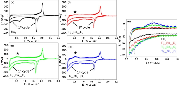
Cyclic voltammetry (CV) measurements at a scan rate of 0.05 mV s
−1
in the range of 0.05–3 V versus Li/Li
+
, are presented in Fig. 28. A pair of cathodic and anodic peaks were observed in the potential range 1.5 and 2.3 V versus Li/Li
+
, relating to Li-ion insertion into and extraction from the interstitial octahedral site of TiO2 (see equation) [81]. Under normal circumstances, a two-phase reaction is expected to occur during lithiation with phase equilibrium of the Li-poor Li0.01 TiO2 (tetragonal) phase and the Li-rich Li0.55 TiO2 (orthorhombic) phase [19, 20]. The detected specific current peak decreased with higher amount of Sn, thereby reducing the amount of pure TiO2 . The pure TiO2 sample showed virtually no electrochemical activity in the potential range between 1.3 and 1 V versus Li/Li
+
during the first cycle. The increasing specific current during the first cycle between 1 and 0.05 V versus Li/Li
+
, is attributed to solid electrolyte interface (SEI) formation (electrolyte destruction) at lower potentials [13]. There was also likely to be substantive SEI formation at the crystallite surfaces of the Sn-doped materials compared to the undoped TiO2 , as there was significant electrochemical activity in the range of 1.3 to 1 V versus Li/Li
+
for the former. However, as the surface area decreases with higher Sn-loading, the initial capacity loss due to the SEI formation may be expected to decrease. The general trend in fact showed that with higher Sn-loading, the initial irreversible capacity loss increased (from 363 mAh g
−1
for the pure TiO2 and 467 mAh g
−1
for Ti0.85 Sn0.15 O2 ).
Cyclic voltammograms for the 1st and 2nd cycles for the as-prepared Nano-powder in the potential range of 0.05 and 3 V versus Li/Li
+
for an applied scan rate of 0.05 mV s
−1
for a undoped anatase TiO2 , b Ti0.94 Sn0.06 O2 , c Ti0.89 Sn0.11 O2 , and d Ti0.85 Sn0.15 O2 . e Specific current versus potential of the 2nd cycle for all materials at lower potentials. The specific current was calculated by taking into account the active material mass loadings [81]
Conclusion
1.
This article discusses silicon anodes as a representative of alloy anodes. It was observed that the only solution to solve the shredding problem is to use nanotechnology. In this paper, the importance of nanomaterial synthesis was expressed. In summary, how to use nanomaterials with different morphologies to solve the problem and improve power. Although various morphologies were discussed, there was no discussion of structural engineering and the use of carbon conductive materials, which will be discussed in future articles. This was one of the methods of establishing electrical bonding for nanoparticles. There are various structures to prevent the nanoparticles from breaking, the art of which is to create different geometries and the method of their preparation.
2.
This article discusses SEI, which is one of the most important topics in most anodes and some high voltage cathodes. This article discussed the problem of alloy anode fragmentation, while which is due to the continuous growth of SEI. It turned out that in order to have a proper cycle life, this problem must be overcome. According to the given examples, using a suitable design at the nanoscale, in addition to providing free volume change of silicon, this volume change does not occur in contact with the electrolyte.
3.
The carbon coating on the anode can increase the conductivity from 13–110 to 2.05 S/cm. Doping can enhance performance by increasing the conductivity of electrons and even ions and providing more space within the network along with Nano sizing, which may be appropriate for new projects, which is more a Nano-topic in Nano synthesis than how it accompanies matter. Synthesize with Nano-dimensional doping until there is a discussion about the effect of Nano on improving anode performance. This article discusses titanium oxide anodes, which is one of the most commercially important anodes. It was found that nanotechnology greatly improves the performance of these anodes. Nano sizing has also been shown to affect even the electrochemical and chemical-physical nature (such as charge–discharge curve deformation and greater capacity in surface layers).
4.
In this paper, exchange anodes are introduced and their complex operation is described. It was found that many problems, such as alloy anodes, can be solved by Nano damaging the active material. The special effects of Nano were expressed as a change in mechanism.
Availability of Data and Materials
All data generated or analyzed during this study are included in this published article.