

제조공정

산업 제조
<메인 클래스="사이트 메인" id="메인">
이 튜토리얼에서는 Arduino와 함께 MPU6050 가속도계 및 자이로스코프 센서를 사용하는 방법을 배웁니다. 먼저 MPU6050의 작동 원리와 데이터를 읽는 방법을 설명한 다음 실제 예제를 두 개 만들어 보겠습니다.
다음 비디오를 보거나 아래에 작성된 튜토리얼을 읽을 수 있습니다.
첫 번째 예제에서는 Processing 개발 환경을 사용하여 센서 방향의 3D 시각화를 만들고 두 번째 예제에서는 간단한 자체 안정화 플랫폼 또는 DIY Gimbal을 만듭니다. MPU6050 방향과 융합된 가속도계 및 자이로스코프 데이터를 기반으로 플랫폼 레벨을 유지하는 3개의 서보를 제어합니다.
MPU6050 IMU에는 3축 가속도계와 3축 자이로스코프가 단일 칩에 통합되어 있습니다.
자이로스코프는 X, Y 및 Z 축을 따라 시간 경과에 따른 각도 위치의 변화 속도 또는 회전 속도를 측정합니다. 측정을 위해 MEMS 기술과 코리올리 효과를 사용하지만 이에 대한 자세한 내용은 내 특정 MEMS 센서 작동 방법 자습서를 확인할 수 있습니다. 자이로스코프의 출력은 초당 각도이므로 각 위치를 얻으려면 각속도를 통합하기만 하면 됩니다.
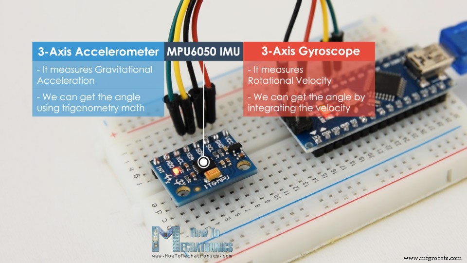
반면 MPU6050 가속도계는 ADXL345 가속도계 센서에 대한 이전 비디오에서 설명한 것과 같은 방식으로 가속도를 측정합니다. 간단히 말해서, 3축을 따라 중력 가속도를 측정할 수 있으며 일부 삼각법 수학을 사용하여 센서가 위치하는 각도를 계산할 수 있습니다. 따라서 가속도계와 자이로스코프 데이터를 융합하거나 결합하면 센서 방향에 대한 매우 정확한 정보를 얻을 수 있습니다.
MPU6050 IMU는 6개의 출력 또는 3개의 가속도계 출력과 3개의 자이로스코프 출력으로 인해 6축 모션 추적 장치 또는 6 DoF(6자유도) 장치라고도 합니다.
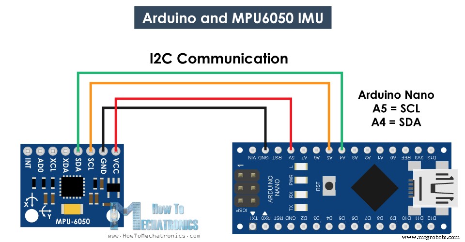
Arduino를 사용하여 MPU6050 센서에서 데이터를 연결하고 읽는 방법을 살펴보겠습니다. 우리는 Arduino와의 통신을 위해 I2C 프로토콜을 사용하고 있으므로 연결을 위한 두 개의 와이어와 전원 공급을 위한 두 개의 와이어만 필요합니다.
아래 링크에서 이 Arduino 튜토리얼에 필요한 구성요소를 얻을 수 있습니다.
다음은 MPU6050 센서에서 데이터를 읽기 위한 Arduino 코드입니다. 코드 아래에서 자세한 설명을 찾을 수 있습니다.
/*
   Arduino and MPU6050 Accelerometer and Gyroscope Sensor Tutorial
   by Dejan, https://howtomechatronics.com
*/
#include <Wire.h>
const int MPU = 0x68; // MPU6050 I2C address
float AccX, AccY, AccZ;
float GyroX, GyroY, GyroZ;
float accAngleX, accAngleY, gyroAngleX, gyroAngleY, gyroAngleZ;
float roll, pitch, yaw;
float AccErrorX, AccErrorY, GyroErrorX, GyroErrorY, GyroErrorZ;
float elapsedTime, currentTime, previousTime;
int c = 0;
void setup() {
  Serial.begin(19200);
  Wire.begin();                      // Initialize comunication
  Wire.beginTransmission(MPU);       // Start communication with MPU6050 // MPU=0x68
  Wire.write(0x6B);                  // Talk to the register 6B
  Wire.write(0x00);                  // Make reset - place a 0 into the 6B register
  Wire.endTransmission(true);        //end the transmission
  /*
  // Configure Accelerometer Sensitivity - Full Scale Range (default +/- 2g)
  Wire.beginTransmission(MPU);
  Wire.write(0x1C);                  //Talk to the ACCEL_CONFIG register (1C hex)
  Wire.write(0x10);                  //Set the register bits as 00010000 (+/- 8g full scale range)
  Wire.endTransmission(true);
  // Configure Gyro Sensitivity - Full Scale Range (default +/- 250deg/s)
  Wire.beginTransmission(MPU);
  Wire.write(0x1B);                   // Talk to the GYRO_CONFIG register (1B hex)
  Wire.write(0x10);                   // Set the register bits as 00010000 (1000deg/s full scale)
  Wire.endTransmission(true);
  delay(20);
  */
  // Call this function if you need to get the IMU error values for your module
  calculate_IMU_error();
  delay(20);
}
void loop() {
  // === Read acceleromter data === //
  Wire.beginTransmission(MPU);
  Wire.write(0x3B); // Start with register 0x3B (ACCEL_XOUT_H)
  Wire.endTransmission(false);
  Wire.requestFrom(MPU, 6, true); // Read 6 registers total, each axis value is stored in 2 registers
  //For a range of +-2g, we need to divide the raw values by 16384, according to the datasheet
  AccX = (Wire.read() << 8 | Wire.read()) / 16384.0; // X-axis value
  AccY = (Wire.read() << 8 | Wire.read()) / 16384.0; // Y-axis value
  AccZ = (Wire.read() << 8 | Wire.read()) / 16384.0; // Z-axis value
  // Calculating Roll and Pitch from the accelerometer data
  accAngleX = (atan(AccY / sqrt(pow(AccX, 2) + pow(AccZ, 2))) * 180 / PI) - 0.58; // AccErrorX ~(0.58) See the calculate_IMU_error()custom function for more details
  accAngleY = (atan(-1 * AccX / sqrt(pow(AccY, 2) + pow(AccZ, 2))) * 180 / PI) + 1.58; // AccErrorY ~(-1.58)
  // === Read gyroscope data === //
  previousTime = currentTime;        // Previous time is stored before the actual time read
  currentTime = millis();            // Current time actual time read
  elapsedTime = (currentTime - previousTime) / 1000; // Divide by 1000 to get seconds
  Wire.beginTransmission(MPU);
  Wire.write(0x43); // Gyro data first register address 0x43
  Wire.endTransmission(false);
  Wire.requestFrom(MPU, 6, true); // Read 4 registers total, each axis value is stored in 2 registers
  GyroX = (Wire.read() << 8 | Wire.read()) / 131.0; // For a 250deg/s range we have to divide first the raw value by 131.0, according to the datasheet
  GyroY = (Wire.read() << 8 | Wire.read()) / 131.0;
  GyroZ = (Wire.read() << 8 | Wire.read()) / 131.0;
  // Correct the outputs with the calculated error values
  GyroX = GyroX + 0.56; // GyroErrorX ~(-0.56)
  GyroY = GyroY - 2; // GyroErrorY ~(2)
  GyroZ = GyroZ + 0.79; // GyroErrorZ ~ (-0.8)
  // Currently the raw values are in degrees per seconds, deg/s, so we need to multiply by sendonds (s) to get the angle in degrees
  gyroAngleX = gyroAngleX + GyroX * elapsedTime; // deg/s * s = deg
  gyroAngleY = gyroAngleY + GyroY * elapsedTime;
  yaw =  yaw + GyroZ * elapsedTime;
  // Complementary filter - combine acceleromter and gyro angle values
  roll = 0.96 * gyroAngleX + 0.04 * accAngleX;
  pitch = 0.96 * gyroAngleY + 0.04 * accAngleY;

  // Print the values on the serial monitor
  Serial.print(roll);
  Serial.print("/");
  Serial.print(pitch);
  Serial.print("/");
  Serial.println(yaw);
}
void calculate_IMU_error() {
  // We can call this funtion in the setup section to calculate the accelerometer and gyro data error. From here we will get the error values used in the above equations printed on the Serial Monitor.
  // Note that we should place the IMU flat in order to get the proper values, so that we then can the correct values
  // Read accelerometer values 200 times
  while (c < 200) {
    Wire.beginTransmission(MPU);
    Wire.write(0x3B);
    Wire.endTransmission(false);
    Wire.requestFrom(MPU, 6, true);
    AccX = (Wire.read() << 8 | Wire.read()) / 16384.0 ;
    AccY = (Wire.read() << 8 | Wire.read()) / 16384.0 ;
    AccZ = (Wire.read() << 8 | Wire.read()) / 16384.0 ;
    // Sum all readings
    AccErrorX = AccErrorX + ((atan((AccY) / sqrt(pow((AccX), 2) + pow((AccZ), 2))) * 180 / PI));
    AccErrorY = AccErrorY + ((atan(-1 * (AccX) / sqrt(pow((AccY), 2) + pow((AccZ), 2))) * 180 / PI));
    c++;
  }
  //Divide the sum by 200 to get the error value
  AccErrorX = AccErrorX / 200;
  AccErrorY = AccErrorY / 200;
  c = 0;
  // Read gyro values 200 times
  while (c < 200) {
    Wire.beginTransmission(MPU);
    Wire.write(0x43);
    Wire.endTransmission(false);
    Wire.requestFrom(MPU, 6, true);
    GyroX = Wire.read() << 8 | Wire.read();
    GyroY = Wire.read() << 8 | Wire.read();
    GyroZ = Wire.read() << 8 | Wire.read();
    // Sum all readings
    GyroErrorX = GyroErrorX + (GyroX / 131.0);
    GyroErrorY = GyroErrorY + (GyroY / 131.0);
    GyroErrorZ = GyroErrorZ + (GyroZ / 131.0);
    c++;
  }
  //Divide the sum by 200 to get the error value
  GyroErrorX = GyroErrorX / 200;
  GyroErrorY = GyroErrorY / 200;
  GyroErrorZ = GyroErrorZ / 200;
  // Print the error values on the Serial Monitor
  Serial.print("AccErrorX: ");
  Serial.println(AccErrorX);
  Serial.print("AccErrorY: ");
  Serial.println(AccErrorY);
  Serial.print("GyroErrorX: ");
  Serial.println(GyroErrorX);
  Serial.print("GyroErrorY: ");
  Serial.println(GyroErrorY);
  Serial.print("GyroErrorZ: ");
  Serial.println(GyroErrorZ);
}Code language: Arduino (arduino)
코드 설명: 따라서 먼저 I2C 통신에 사용되는 Wire.h 라이브러리를 포함하고 데이터를 저장하는 데 필요한 몇 가지 변수를 정의해야 합니다.
설정 섹션에서 와이어 라이브러리를 초기화하고 전원 관리 레지스터를 통해 센서를 재설정해야 합니다. 그렇게 하려면 레지스터 주소를 볼 수 있는 센서의 데이터시트를 살펴봐야 합니다.
<그림 클래스="aligncenter">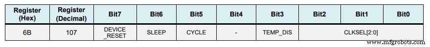
또한 원하는 경우 구성 레지스터를 사용하여 가속도계와 자이로스코프의 전체 범위를 선택할 수 있습니다. 이 예에서는 가속도계에 기본 +- 2g 범위를 사용하고 자이로스코프에 250도/초 범위를 사용하므로 코드의 이 부분은 주석으로 남겨두겠습니다.
// Configure Accelerometer Sensitivity - Full Scale Range (default +/- 2g)
  Wire.beginTransmission(MPU);
  Wire.write(0x1C);                  //Talk to the ACCEL_CONFIG register (1C hex)
  Wire.write(0x10);                  //Set the register bits as 00010000 (+/- 8g full scale range)
  Wire.endTransmission(true);
  // Configure Gyro Sensitivity - Full Scale Range (default +/- 250deg/s)
  Wire.beginTransmission(MPU);
  Wire.write(0x1B);                   // Talk to the GYRO_CONFIG register (1B hex)
  Wire.write(0x10);                   // Set the register bits as 00010000 (1000deg/s full scale)
  Wire.endTransmission(true);
  */Code language: Arduino (arduino)
루프 섹션에서 가속도계 데이터를 읽는 것으로 시작합니다. 각 축의 데이터는 2바이트 또는 레지스터에 저장되며 센서의 데이터시트에서 이러한 레지스터의 주소를 볼 수 있습니다.
<그림 클래스="aligncenter">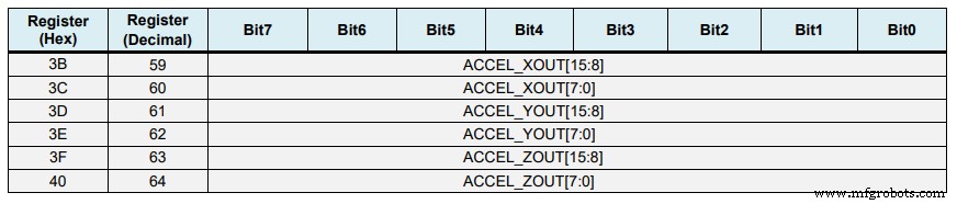
그것들을 모두 읽기 위해 우리는 첫 번째 레지스터부터 시작하고 requiestFrom() 함수를 사용하여 X, Y 및 Z 축에 대한 6개 레지스터를 모두 읽도록 요청합니다. 그런 다음 각 레지스터에서 데이터를 읽고 출력이 2의 보수이므로 올바른 값을 얻기 위해 적절하게 결합합니다.
// === Read acceleromter data === //
  Wire.beginTransmission(MPU);
  Wire.write(0x3B); // Start with register 0x3B (ACCEL_XOUT_H)
  Wire.endTransmission(false);
  Wire.requestFrom(MPU, 6, true); // Read 6 registers total, each axis value is stored in 2 registers
  //For a range of +-2g, we need to divide the raw values by 16384, according to the datasheet
  AccX = (Wire.read() << 8 | Wire.read()) / 16384.0; // X-axis value
  AccY = (Wire.read() << 8 | Wire.read()) / 16384.0; // Y-axis value
  AccZ = (Wire.read() << 8 | Wire.read()) / 16384.0; // Z-axis valueCode language: Arduino (arduino)
각도 계산에 적합한 -1g에서 +1g까지의 출력 값을 얻기 위해 이전에 선택한 감도로 출력을 나눕니다.
<그림 클래스="aligncenter">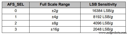
마지막으로 이 두 공식을 사용하여 가속도계 데이터에서 롤 및 피치 각도를 계산합니다.
// Calculating Roll and Pitch from the accelerometer data
  accAngleX = (atan(AccY / sqrt(pow(AccX, 2) + pow(AccZ, 2))) * 180 / PI) - 0.58; // AccErrorX ~(0.58) See the calculate_IMU_error()custom function for more details
  accAngleY = (atan(-1 * AccX / sqrt(pow(AccY, 2) + pow(AccZ, 2))) * 180 / PI) + 1.58; // AccErrorY ~(-1.58)Code language: Arduino (arduino)
다음으로 동일한 방법을 사용하여 자이로스코프 데이터를 얻습니다.
<그림 클래스="aligncenter">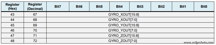
6개의 자이로스코프 레지스터를 읽고 데이터를 적절하게 결합한 다음 이전에 선택한 감도로 나누어 초당 도 단위로 출력을 얻습니다.
// === Read gyroscope data === //
  previousTime = currentTime;        // Previous time is stored before the actual time read
  currentTime = millis();            // Current time actual time read
  elapsedTime = (currentTime - previousTime) / 1000; // Divide by 1000 to get seconds
  Wire.beginTransmission(MPU);
  Wire.write(0x43); // Gyro data first register address 0x43
  Wire.endTransmission(false);
  Wire.requestFrom(MPU, 6, true); // Read 4 registers total, each axis value is stored in 2 registers
  GyroX = (Wire.read() << 8 | Wire.read()) / 131.0; // For a 250deg/s range we have to divide first the raw value by 131.0, according to the datasheet
  GyroY = (Wire.read() << 8 | Wire.read()) / 131.0;
  GyroZ = (Wire.read() << 8 | Wire.read()) / 131.0;Code language: Arduino (arduino)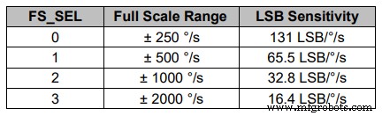
여기에서 약간의 계산된 오류 값으로 출력 값을 수정한 것을 알 수 있습니다. 이 값을 1분 안에 얻는 방법을 설명하겠습니다. 따라서 출력은 초당 도 단위이므로 이제 도를 얻기 위해 시간을 곱해야 합니다. 시간 값은 millis() 함수를 사용하여 각 읽기 반복 전에 캡처됩니다.
// Correct the outputs with the calculated error values
  GyroX = GyroX + 0.56; // GyroErrorX ~(-0.56)
  GyroY = GyroY - 2; // GyroErrorY ~(2)
  GyroZ = GyroZ + 0.79; // GyroErrorZ ~ (-0.8)
  // Currently the raw values are in degrees per seconds, deg/s, so we need to multiply by sendonds (s) to get the angle in degrees
  gyroAngleX = gyroAngleX + GyroX * elapsedTime; // deg/s * s = deg
  gyroAngleY = gyroAngleY + GyroY * elapsedTime;
  yaw =  yaw + GyroZ * elapsedTime;Code language: Arduino (arduino)
마지막으로 보완 필터를 사용하여 가속도계와 자이로스코프 데이터를 융합합니다. 여기서 자이로스코프 데이터의 96%는 매우 정확하고 외력에 영향을 받지 않기 때문에 가져옵니다. 자이로스코프의 단점은 드리프트하거나 시간이 지남에 따라 출력에 오류가 발생한다는 것입니다. 따라서 장기적으로 가속도계의 데이터(이 경우 4%)를 사용하여 자이로스코프 드리프트 오류를 제거하기에 충분합니다.
// Complementary filter - combine acceleromter and gyro angle values
  roll = 0.96 * gyroAngleX + 0.04 * accAngleX;
  pitch = 0.96 * gyroAngleY + 0.04 * accAngleY;Code language: Arduino (arduino)
그러나 가속도계 데이터에서 Yaw를 계산할 수 없으므로 이에 대한 보완 필터를 구현할 수 없습니다.
결과를 살펴보기 전에 오류 수정 값을 얻는 방법에 대해 간단히 설명하겠습니다. 이러한 오류를 계산하기 위해 센서가 평평한 정지 위치에 있는 동안 compute_IMU_error() 사용자 정의 함수를 호출할 수 있습니다. 여기서 우리는 모든 출력에 대해 200개의 판독값을 수행하고 합한 다음 200으로 나눕니다. 센서를 평평한 정지 위치에 유지하기 때문에 예상 출력 값은 0이어야 합니다. 따라서 이 계산을 통해 센서의 평균 오류를 얻을 수 있습니다. 만듭니다.
void calculate_IMU_error() {
  // We can call this funtion in the setup section to calculate the accelerometer and gyro data error. From here we will get the error values used in the above equations printed on the Serial Monitor.
  // Note that we should place the IMU flat in order to get the proper values, so that we then can the correct values
  // Read accelerometer values 200 times
  while (c < 200) {
    Wire.beginTransmission(MPU);
    Wire.write(0x3B);
    Wire.endTransmission(false);
    Wire.requestFrom(MPU, 6, true);
    AccX = (Wire.read() << 8 | Wire.read()) / 16384.0 ;
    AccY = (Wire.read() << 8 | Wire.read()) / 16384.0 ;
    AccZ = (Wire.read() << 8 | Wire.read()) / 16384.0 ;
    // Sum all readings
    AccErrorX = AccErrorX + ((atan((AccY) / sqrt(pow((AccX), 2) + pow((AccZ), 2))) * 180 / PI));
    AccErrorY = AccErrorY + ((atan(-1 * (AccX) / sqrt(pow((AccY), 2) + pow((AccZ), 2))) * 180 / PI));
    c++;
  }
  //Divide the sum by 200 to get the error value
  AccErrorX = AccErrorX / 200;
  AccErrorY = AccErrorY / 200;
  c = 0;
  // Read gyro values 200 times
  while (c < 200) {
    Wire.beginTransmission(MPU);
    Wire.write(0x43);
    Wire.endTransmission(false);
    Wire.requestFrom(MPU, 6, true);
    GyroX = Wire.read() << 8 | Wire.read();
    GyroY = Wire.read() << 8 | Wire.read();
    GyroZ = Wire.read() << 8 | Wire.read();
    // Sum all readings
    GyroErrorX = GyroErrorX + (GyroX / 131.0);
    GyroErrorY = GyroErrorY + (GyroY / 131.0);
    GyroErrorZ = GyroErrorZ + (GyroZ / 131.0);
    c++;
  }
  //Divide the sum by 200 to get the error value
  GyroErrorX = GyroErrorX / 200;
  GyroErrorY = GyroErrorY / 200;
  GyroErrorZ = GyroErrorZ / 200;
  // Print the error values on the Serial Monitor
  Serial.print("AccErrorX: ");
  Serial.println(AccErrorX);
  Serial.print("AccErrorY: ");
  Serial.println(AccErrorY);
  Serial.print("GyroErrorX: ");
  Serial.println(GyroErrorX);
  Serial.print("GyroErrorY: ");
  Serial.println(GyroErrorY);
  Serial.print("GyroErrorZ: ");
  Serial.println(GyroErrorZ);
}Code language: Arduino (arduino)
직렬 모니터에 값을 인쇄하기만 하면 됩니다. 일단 값을 알게 되면 앞서 표시된 것처럼 롤 및 피치 계산과 3개의 자이로스코프 출력에 대해 코드에서 이를 구현할 수 있습니다.
<그림 클래스="aligncenter">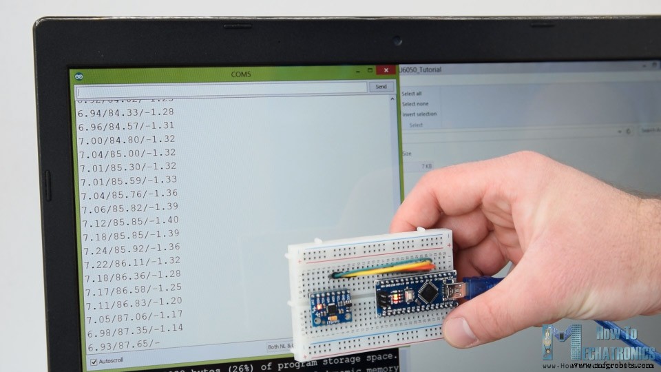
마지막으로 Serial.print 기능을 사용하여 직렬 모니터에서 Roll, Pitch 및 Yaw 값을 인쇄하고 센서가 제대로 작동하는지 확인할 수 있습니다.
다음으로 3D 시각화 예제를 만들기 위해 Arduino가 Processing 개발 환경의 직렬 포트를 통해 보내는 이 데이터를 수락하기만 하면 됩니다. 전체 처리 코드는 다음과 같습니다.
/*
    Arduino and MPU6050 IMU - 3D Visualization Example
     by Dejan, https://howtomechatronics.com
*/
import processing.serial.*;
import java.awt.event.KeyEvent;
import java.io.IOException;
Serial myPort;
String data="";
float roll, pitch,yaw;
void setup() {
  size (2560, 1440, P3D);
  myPort = new Serial(this, "COM7", 19200); // starts the serial communication
  myPort.bufferUntil('\n');
}
void draw() {
  translate(width/2, height/2, 0);
  background(233);
  textSize(22);
  text("Roll: " + int(roll) + "     Pitch: " + int(pitch), -100, 265);
  // Rotate the object
  rotateX(radians(-pitch));
  rotateZ(radians(roll));
  rotateY(radians(yaw));

  // 3D 0bject
  textSize(30);
  fill(0, 76, 153);
  box (386, 40, 200); // Draw box
  textSize(25);
  fill(255, 255, 255);
  text("www.HowToMechatronics.com", -183, 10, 101);
  //delay(10);
  //println("ypr:\t" + angleX + "\t" + angleY); // Print the values to check whether we are getting proper values
}
// Read data from the Serial Port
void serialEvent (Serial myPort) {
  // reads the data from the Serial Port up to the character '.' and puts it into the String variable "data".
  data = myPort.readStringUntil('\n');
  // if you got any bytes other than the linefeed:
  if (data != null) {
    data = trim(data);
    // split the string at "/"
    String items[] = split(data, '/');
    if (items.length > 1) {
      //--- Roll,Pitch in degrees
      roll = float(items[0]);
      pitch = float(items[1]);
      yaw = float(items[2]);
    }
  }
}Code language: Arduino (arduino)
여기에서 Arduino에서 들어오는 데이터를 읽고 적절한 Roll, Pitch 및 Yaw 변수에 넣습니다. 기본 그리기 루프에서 이 값을 사용하여 3D 개체를 회전합니다. 이 경우 특정 색상과 텍스트가 있는 간단한 상자입니다.
스케치를 실행하면 MPU6050 센서가 방향 추적에 얼마나 좋은지 알 수 있습니다. 3D 개체는 센서의 방향을 매우 정확하게 추적하고 응답성이 매우 뛰어납니다.
<그림 클래스="aligncenter">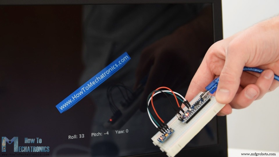
내가 언급했듯이 유일한 단점은 Yaw에 대해 보완적인 필터를 사용할 수 없기 때문에 시간이 지남에 따라 Yaw가 표류한다는 것입니다. 이를 개선하려면 추가 센서를 사용해야 합니다. 이것은 일반적으로 자이로스코프 Yaw 드리프트에 대한 장기 보정으로 사용할 수 있는 자력계입니다. 그러나 MPU6050에는 실제로 데이터의 온보드 계산에 사용되는 Digital Motion Processor라는 기능이 있으며 Yaw 드리프트를 제거할 수 있습니다.
<그림 클래스="aligncenter">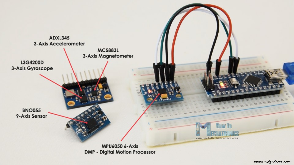
다음은 사용 중인 디지털 모션 프로세서와 동일한 3D 예입니다. 이제 Yaw 드리프트 없이 방향 추적이 얼마나 정확한지 알 수 있습니다. 온보드 프로세서는 3차원에서 개체의 방향과 회전을 나타내는 데 사용되는 쿼터니언을 계산하고 출력할 수도 있습니다. 이 예에서 우리는 오일러 각도를 사용할 때 발생하는 짐벌 잠금을 겪지 않는 방향을 나타내기 위해 실제로 쿼터니언을 사용하고 있습니다.
<그림 클래스="aligncenter">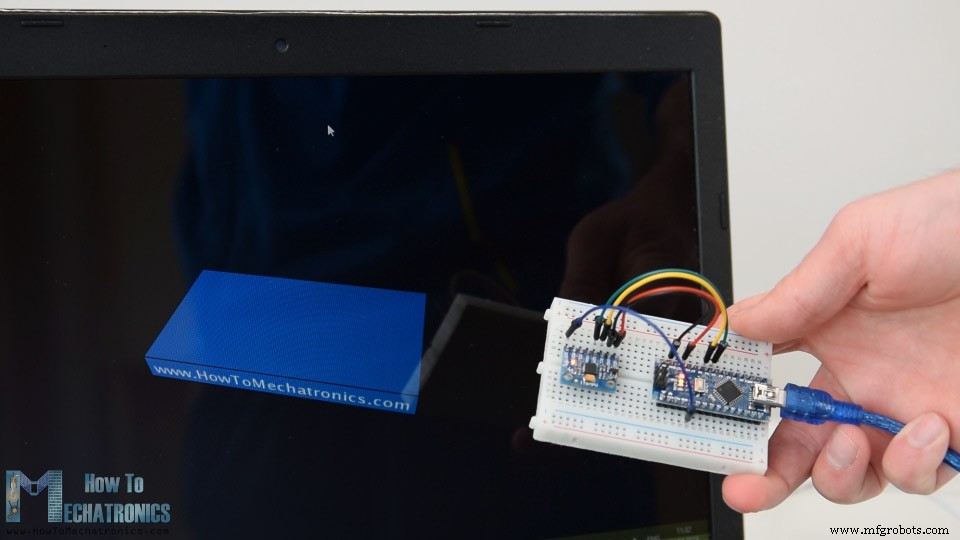
그럼에도 불구하고 센서에서 이 데이터를 얻는 것은 앞에서 설명한 것보다 조금 더 복잡합니다. 먼저 Arduino 디지털 핀에 연결하고 추가 배선을 해야 합니다. MPU6050에서 이 데이터 유형을 읽는 데 사용되는 인터럽트 핀입니다.
<그림 클래스="aligncenter">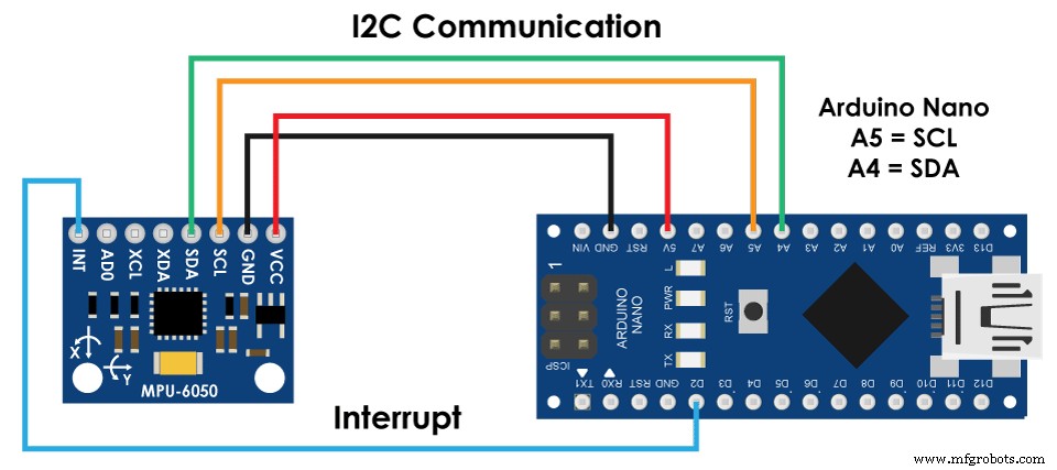
코드도 약간 더 복잡하므로 Jeff Rowberg의 i2cdevlib 라이브러리를 사용합니다. 이 라이브러리는 GitHub에서 다운로드할 수 있으며 웹사이트 기사에 대한 링크를 포함할 것입니다.
라이브러리를 설치하면 라이브러리에서 MPU6050_DMP6 예제를 열 수 있습니다. 이 예는 각 줄에 대한 주석으로 잘 설명되어 있습니다.
<그림 클래스="aligncenter">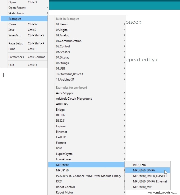
여기에서 쿼터니언, 오일러 각도, 요, 피치 및 롤, 가속 값 또는 3D 시각화를 위한 쿼터니언 등 원하는 출력 유형을 선택할 수 있습니다. 이 라이브러리에는 3D 시각화 예제에 대한 처리 스케치도 포함되어 있습니다. 이전 예제와 같이 상자 모양을 얻도록 수정했습니다. 다음은 선택한 "OUTPUT_TEAPOT" 출력에 대해 MPU6050_DPM6 예제와 함께 작동하는 3D 시각화 처리 코드입니다.
/*
    Arduino and MPU6050 IMU - 3D Visualization Example
     by Dejan, https://howtomechatronics.com
*/
import processing.serial.*;
import java.awt.event.KeyEvent;
import java.io.IOException;
Serial myPort;
String data="";
float roll, pitch,yaw;
void setup() {
  size (2560, 1440, P3D);
  myPort = new Serial(this, "COM7", 19200); // starts the serial communication
  myPort.bufferUntil('\n');
}
void draw() {
  translate(width/2, height/2, 0);
  background(233);
  textSize(22);
  text("Roll: " + int(roll) + "     Pitch: " + int(pitch), -100, 265);
  // Rotate the object
  rotateX(radians(-pitch));
  rotateZ(radians(roll));
  rotateY(radians(yaw));

  // 3D 0bject
  textSize(30);
  fill(0, 76, 153);
  box (386, 40, 200); // Draw box
  textSize(25);
  fill(255, 255, 255);
  text("www.HowToMechatronics.com", -183, 10, 101);
  //delay(10);
  //println("ypr:\t" + angleX + "\t" + angleY); // Print the values to check whether we are getting proper values
}
// Read data from the Serial Port
void serialEvent (Serial myPort) {
  // reads the data from the Serial Port up to the character '.' and puts it into the String variable "data".
  data = myPort.readStringUntil('\n');
  // if you got any bytes other than the linefeed:
  if (data != null) {
    data = trim(data);
    // split the string at "/"
    String items[] = split(data, '/');
    if (items.length > 1) {
      //--- Roll,Pitch in degrees
      roll = float(items[0]);
      pitch = float(items[1]);
      yaw = float(items[2]);
    }
  }
}Code language: Arduino (arduino)
그래서 여기에서 serialEvent() 함수를 사용하여 Arduino에서 오는 쿼터니언을 수신하고 주 그리기 루프에서 이를 사용하여 3D 개체를 회전합니다. 스케치를 실행하면 쿼터니언이 3차원에서 개체를 회전하는 데 얼마나 좋은지 알 수 있습니다.
이 튜토리얼에 과부하가 걸리지 않도록 두 번째 예시인 DIY Arduino Gimbal 또는 자체 안정화 플랫폼을 별도의 기사에 게재했습니다.
<그림 클래스="aligncenter">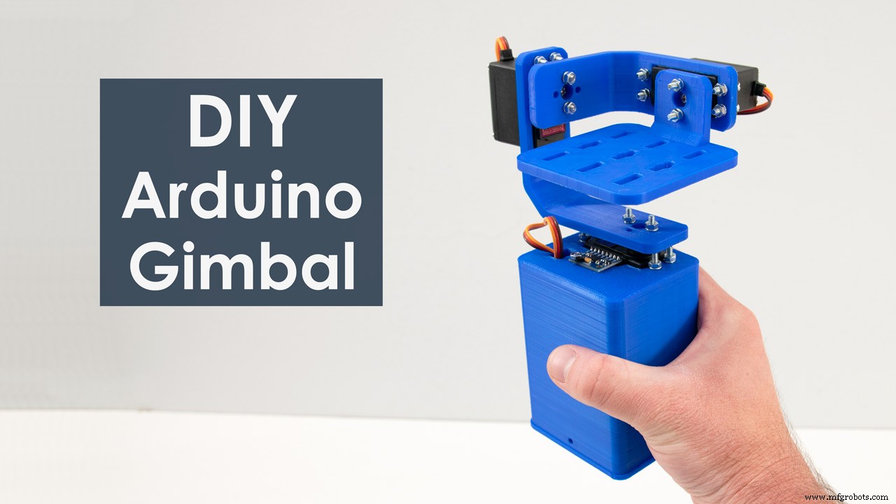
아래 댓글 섹션에서 이 튜토리얼과 관련된 질문을 자유롭게 하고 내 Arduino 프로젝트 컬렉션을 확인하는 것도 잊지 마세요.
제조공정
Arduino 자습서 시리즈의 네 번째 Arduino 자습서에 오신 것을 환영합니다. 이 튜토리얼에서는 PWM(Pulse Width Modulation)을 사용하여 DC 및 서보 모터를 제어하는 방법을 배웁니다. 이것은 따라하기 쉬운 단계별 비디오 자습서입니다. 또한 동영상 아래에서 이 튜토리얼에 필요한 부품과 동영상의 예제 소스 코드를 찾을 수 있습니다. 첫 번째 예에 필요한 구성요소 DC 모터 ........................................................... 또는 CPU 팬
Arduino 자습서 시리즈의 두 번째 Arduino 자습서에 오신 것을 환영합니다. 이 튜토리얼에서는 디지털 입력 및 출력 핀이 작동하는 방식을 배우고 버튼과 LED를 사용하여 몇 가지 예를 만들 것입니다. 또한 PWM(Pulse Width Modulation)이 무엇인지 배우고 PWM을 사용하여 LED 밝기를 제어하는 예를 만듭니다. 이것은 따라하기 쉬운 단계별 비디오 자습서입니다. 또한 동영상 아래에서 이 튜토리얼에 필요한 부품과 동영상의 예제 소스 코드를 찾을 수 있습니다. 이 가이드에 필요한 구성요소 Ardui