아날로그 vs 디지털 IQ 결합: RF 시스템에 적합한 접근법 선택하기
I와 Q 결합은 어떻게 해야 할까? 아날로그 방식인가 디지털 방식인가? 이 글에서는 아날로그와 디지털 IQ 접근법의 기초를 다룹니다.
아날로그 IQ 변조기(송신기용)와 IQ 복조기(수신기용)는 수십 년간 사용되어 왔습니다([1]~[3]).
최근 1~4GHz의 IF를 직접 샘플링할 수 있는 새로운 A/D, D/A 컨버터가 도입되었습니다(제2, 3, 4 나이퀴스트 존에서의 샘플링)([4]~[7]). 이들 고속 디지털 로직과 결합되어 결합(A/D용)과 분리(D/A용)를 디지털로 수행할 수 있게 되었습니다([8]~[21]). 이는 Figure 1(a)(변조기용)와 Figure 1(b)(복조기용)에서 데이터 컨버터(DAC 또는 ADC)가 위치 "D"에 있는 것으로 설명됩니다.
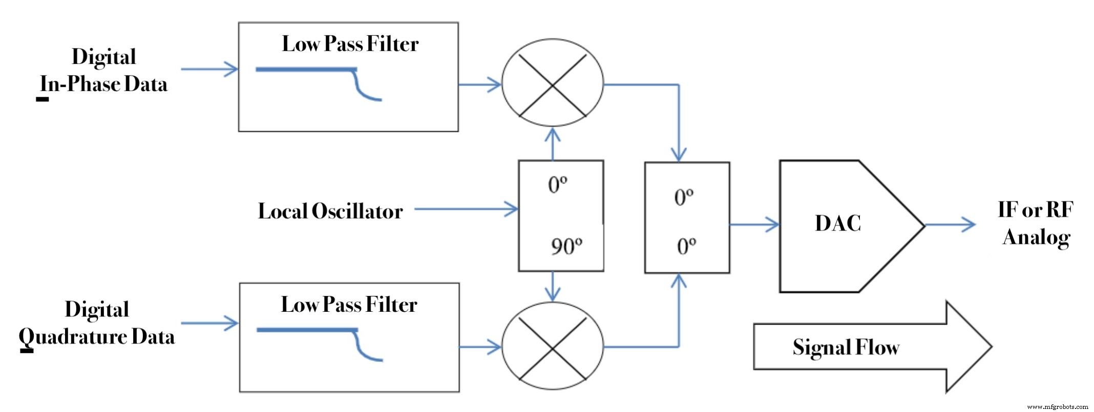
Figure 1(a). 변조기
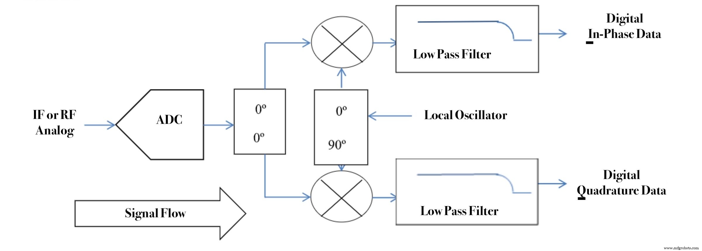
Figure 1(b). 복조기
반면 통합 아날로그 I, Q 결합기와 분리기는 I와 Q 경로 간에 매우 좋은 매칭을 제공하여 아날로그 방식의 일부 우려를 해소합니다. 아날로그 방식은 IF에서 직접 샘플링하는 것보다 2배의 데이터 컨버터(A/D 또는 D/A)가 필요하지만, 더 낮은 샘플링 속도로 동작하므로 더 저렴하고 전력 소모가 적습니다. 이는 Figure 1(a)(변조기용)와 Figure 1(b)(복조기용)에서 데이터 컨버터(DAC 또는 ADC)가 위치 "A"에 있는 것으로 설명됩니다.
저자는 이 문제에 대해 고민하기 시작했습니다. 여러 LinkedIn 그룹에서 의견을 구했고 귀중한 답변을 받았습니다. 승인을 받은 분들은 아래에 감사를 표합니다. 또한 이 기능들을 위한 현대 집적 회로(IC)의 특성과 이들 IC에 대해 결정된 성능 요구사항에 대해 알 수 있는 모든 정보를 찾았습니다. 이를 바탕으로 "IQ 변조와 복조를 아날로그로 할 것인가 디지털로 할 것인가?"라는 질문에 답할 수 있는 일반적인 결론을 도출하려 했습니다.
아날로그 IQ 접근법
아날로그 IQ 접근법은 수십 년간 사용되어 왔습니다([1]~[3]). 모든 IF 또는 RF 신호는 다음과 같이 표현될 수 있습니다:
R(t) = I(t)cos(2πft) + Q(t)sin(2πft)
여기서 f는 반송파 주파수, I(t)는 동위상(In-Phase) 성분, Q(t)는 직교(Quadrature) 성분입니다. 아날로그 IQ 변조기는 베이스밴드 신호 I(t)와 Q(t)를 받아 R(t)를 형성합니다. 이는 Figure 1(a)에서 DAC가 위치 A에 있는 것으로 표시됩니다. 아날로그 IQ 복조기는 R(t)를 입력으로 받아 I(t)와 Q(t)를 형성합니다. 이는 Figure 1(b)에서 DAC가 위치 A에 있는 것으로 표시됩니다.
아날로그 방식의 중요한 문제는 두 경로의 이득을 동일하게 유지하고 위상 차이를 정확히 90°로 유지하는 것입니다. 때때로 두 로우패스 필터에 대한 이러한 요구사항이 간과됩니다. 이들은 상당한 신호 에너지가 있는 모든 주파수에서 정확히 이득과 위상이 매칭되어야 합니다. 이러한 요구사항의 더 정확한 정량화와 편차로 인한 손상은 후속 기사에서 다룹니다.
디지털 IQ 접근법
고속 데이터 컨버터(DAC, ADC)의 최근 발전으로, 아날로그 IQ 접근법 섹션에서 논의된 IQ 불균형 문제를 디지털 방식으로 IQ 변조기와 복조기 기능을 구현함으로써 회피하게 되었습니다. 여기서는 이득과 위상을 오차 없이 생성할 수 있습니다([5], [8]~[21]). 변조기의 경우 출력단에 고속 DAC가 있으며, Figure 1(a)에서 DAC가 위치 D에 있는 것으로 표시됩니다. 복조기의 경우 입력단에 고속 ADC가 있으며, Figure 1(b)에서 ADC가 위치 B에 있는 것으로 표시됩니다.
이러한 디지털 접근법은 종종 에일리어싱 효과를 활용하며, 이를 밴드패스 샘플링([22]~[24], [24A], [24B])이라고 합니다. Figure 2(a)는 시간 영역에서 샘플링된 파형을 보여줍니다. Figure 2(b)는 샘플링되지 않은 신호와 샘플링된 신호의 스펙트럼을 보여줍니다. ADC의 샘플 클록은 RF 믹서의 국부 발진기와 같은 기능을 수행합니다. ADC의 경우 아날로그 필터로 하나의 나이퀴스트 존에 있는 신호만 통과시키면, 이 혼합 동작을 이용해 해당 존의 신호를 베이스밴드로 다운컨버전할 수 있습니다.
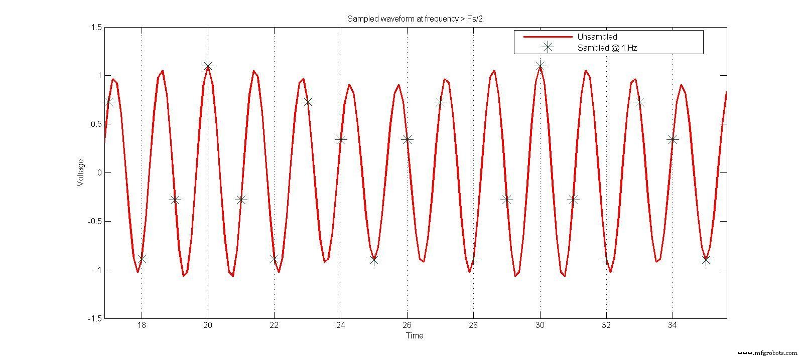
Figure 2(a). 시간 영역 샘플링
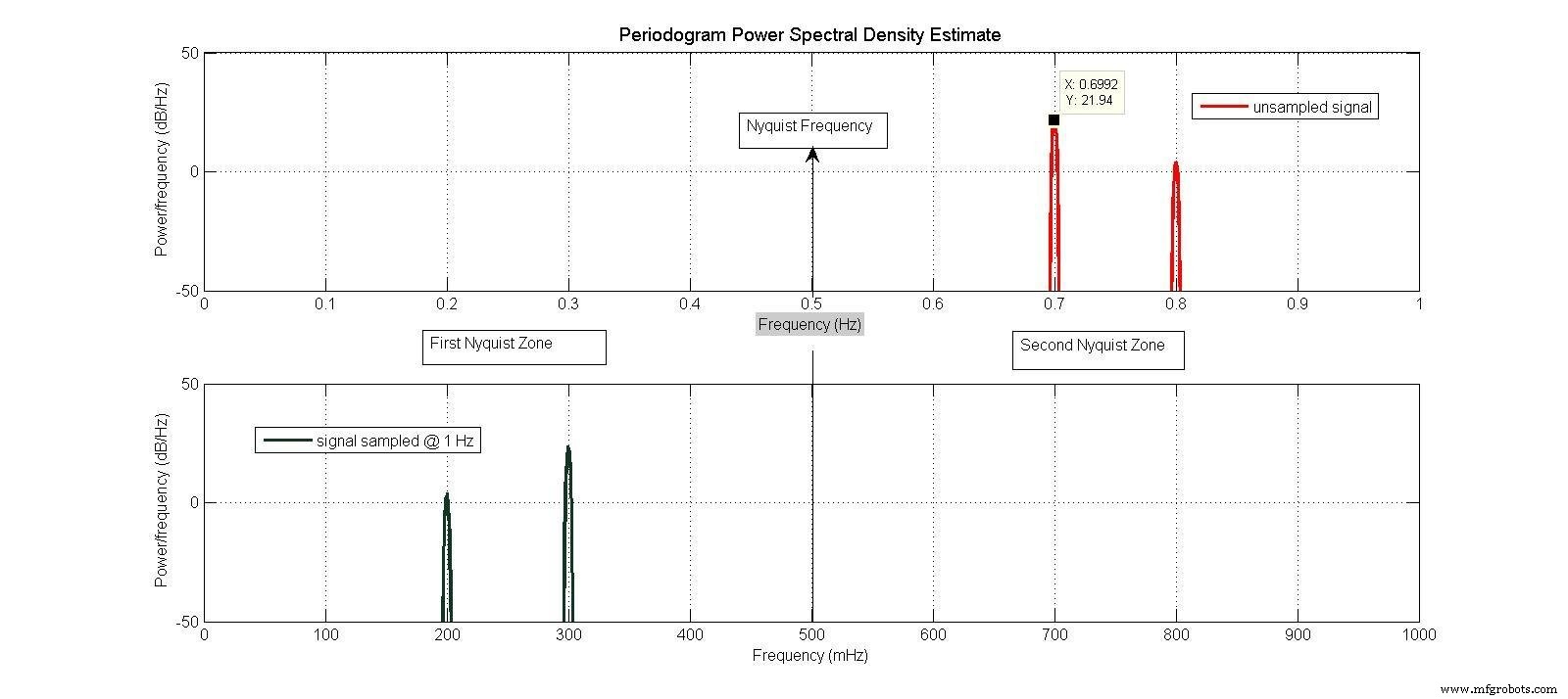
Figure 2(b). 샘플링되지 않은 신호와 샘플링된 신호의 스펙트럼
DAC의 경우 출력을 시간 영역에서 형성하여 고주파에서 성능을 개선할 수 있습니다.
Figure 3(a)는 "일반" 또는 "Non-Return to Zero"(NRZ) DAC 출력을 보여줍니다. 각 샘플 후 다음 샘플까지 출력이 일정하게 유지됩니다. 아날로그 스펙트럼은 Figure 3(b)에 표시됩니다.
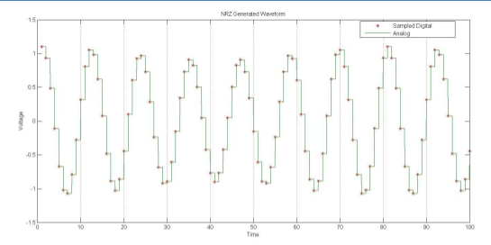
Figure 3(a). 시간 영역 샘플링
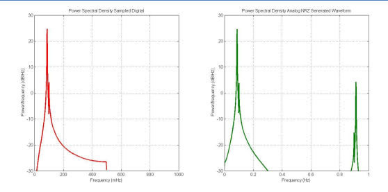
Figure 3(b).
Figure 4(a)는 "Return to Zero"(RZ) DAC 출력을 보여줍니다. 각 샘플 후 출력이 반 샘플 주기 동안 일정하게 유지되었다가 0으로 갑니다. 이는 제2 나이퀴스트 존에서 진폭을 증가시키는 효과가 있으며, Figure 4(b)에 표시됩니다.
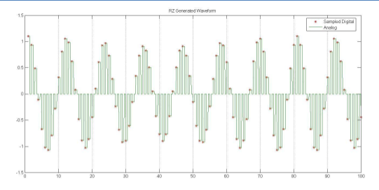
Figure 4(a). 시간 영역 샘플링
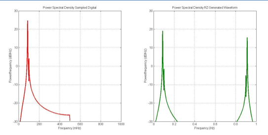
Figure 4(b).
Figure 5(a)는 "Mix" 또는 "RF" DAC 출력을 보여줍니다. 각 샘플 후 출력이 반 샘플 주기 동안 일정하게 유지되었다가 그 음수 값으로 갑니다. 이는 국부 발진기 파형의 양극성을 모두 사용하는 믹서와 동일한 동작입니다. Figure 5(b)에 표시된 아날로그 스펙트럼은 제2 나이퀴스트 존에서 더 큰 진폭을 가집니다. 위 방법 중 어느 것으로 파형이 생성된 후, 원하는 주파수를 로우패스 또는 밴드패스 필터로 걸러내어 원치 않는 에일리어스와 스퓨리어스 응답을 제거해야 합니다.
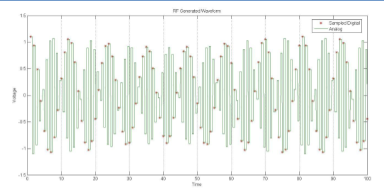
Figure 5(a). 시간 영역 샘플링
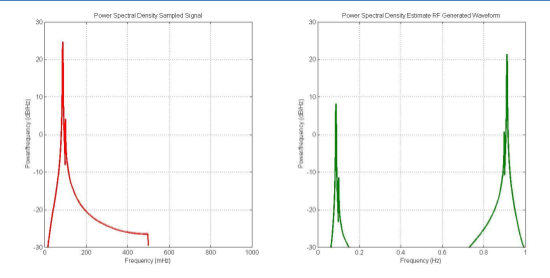
Figure 5(b).
디지털 방식은 직교 불균형 문제를 피합니다. 그러나 모든 데이터 컨버터는 양자화와 샘플링 효과로 인한 고유한 바람직하지 않은 손상을 가집니다. 이러한 효과 일부는 다음 기사에서 다룹니다. 이러한 고속 데이터 컨버터의 비용과 전력 요구사항도 아날로그 IQ 네트워크에 비해 종종 높습니다.
감사의 글
이 보고서에서 다루는 질문이 처음 저자의 마음에 떠올랐을 때, 그는 몇몇 LinkedIn 그룹을 통해 의견을 구했습니다. 여러 유용한 답변을 받았습니다. 개인 정보 사용을 허락해주신 분들은 Gary Kaatz, Khaled Sayed(Consultix-Egypt), Dieter Joos(ON Semiconductor), Jaideep Bose(Asmaitha Wireless Technologies)입니다. 저자는 또한 아내가 무슨 일을 하는지 궁금해했을 것이라며, 집에서 사무실에 틀어박혀 aparentemente 보수도 받지 못하는 일을 하던 남편에게 감사를 전합니다.
참고문헌
다음 참고문헌은 이 시리즈의 각 기사에서 사용됩니다.
아날로그 IQ 변조기 및 복조기: 일반 설명
[1] Shou-Hsien Weng; Che-Hao Shen; Hong-Yeh Chang, "A wide modulation bandwidth bidirectional CMOS IQ modulator/demodulator for microwave and millimeter-wave gigabit applications," Microwave Integrated Circuits Conference (EuMIC), 2012 7th European, vol., no., pp.8,11, 29-30 Oct. 2012
[2] Eamon Nash; "Correcting Imperfections in IQ Modulators to Improve RF Signal Fidelity"; Analog Devices Application Note AN-1039; 2009
[3] Anon; "An IQ Demodulator-Based IF-to-Baseband Receiver with IF and Baseband Variable Gain and Programmable Baseband Filtering"; Analog Devices Circuit Note CN-0320; 2013
고속 데이터 컨버터(DAC, ADC); 일반 정보
[4] Justin Munson; "Understanding High Speed DAC Testing and Evaluation"; Analog Devices Application Note AN-928; 2013
[5] Engel, G.; Fague, D.E.; Toledano, A, "RF digital-to-analog converters enable direct synthesis of communications signals," Communications Magazine, IEEE, vol.50, no.10, pp.108, 116, October 2012
[6] Chris Pearson; "High Speed, Digital to Analog Converters Basics"; Texas Instruments Application Report SLAA523A; 2012
[7] Alex Arrants, Brad Brannon and Rob Reeder; "Understanding High Speed ADC Testing and Evaluation"; Analog Devices Application Note AN-835, 2010.
디지털 IQ 변조기 및 복조기
[8] Samueli, H.; Wong, B.C., "A VLSI architecture for a high-speed all-digital quadrature modulator and demodulator for digital radio applications," Selected Areas in Communications, IEEE Journal on, vol.8, no.8, pp.1512,1519, Oct 1990
[9] Wong, B.C.; Samueli, H., "A 200-MHz all-digital QAM modulator and demodulator in 1.2-nm CMOS for digital radio applications," Solid-State Circuits, IEEE Journal of, vol.26, no.12, pp.1970, 1980, Dec 1991
[10] Ken Gentile; "Digital Quadrature Modulator Gain"; Analog Devices Application Note AN-924; 2009
[11] Lou, J. H.; Kuo, J.B., "A 1.5-V CMOS all-N-logic true-single-phase bootstrapped dynamic-logic circuit suitable for low supply voltage and high-speed pipelined system operation," Circuits and Systems II: Analog and Digital Signal Processing, IEEE Transactions on, vol.46, no.5, pp.628,631, May 1999
[12] Vankka, J.; Sommarek, J.; Ketola, J.; Teikari, I; Halonen, K. A I, "A digital quadrature modulator with on-chip D/A converter," Solid-State Circuits, IEEE Journal of, vol.38, no.10, pp.1635, 1642, Oct. 2003
[13] Yanlin Wu; Dengwei Fu; Willson, A, "A 415 MHz direct digital quadrature modulator in 0.25-nm CMOS", Custom Integrated Circuits Conference, Proceedings of the IEEE 2003, vol., no., pp.287,290, 21-24 Sept. 2003
[14] Sommarek, J.; Vankka, J.; Ketola, J.; Lindeberg, J.; Halonen, K., "A digital modulator with bandpass delta-sigma modulator," Solid-State Circuits Conference, 2004. ESSCIRC 2004. Proceeding of the 30th European, pp.159, 162, 21-23 Sept. 2004
[15] Lin, P.F.; Lou, J. H.; Kuo, J.B., "A CMOS quadrature modulator for wireless communication IC," Circuits and Systems I: Fundamental Theory and Applications, IEEE Transactions on, vol.44, no.6, pp.559, 561, Jun 1997
[16] Parikh, V.K.; Balsara, P.T.; Eliezer, O.E., "All Digital-Quadrature-Modulator Based Wideband Wireless Transmitters," Circuits and Systems I: Regular Papers, IEEE Transactions on, vol.56, no.11, pp.2487, 2497, Nov. 2009
[17] Alavi, M.S.; Staszewski, R.B.; de Vreede, L.C.N.; Long, J.R., "A Wideband13-bit All-Digital I/Q RF-DAC," Microwave Theory and Techniques, IEEE Transactions on, vol.62, no.4, pp.732, 752, April 2014
[18] Inkol, Robert and Saper, Ron; "Digital Quadrature Modulator for Radar ESM Applications" Canadian DEFENCE RESEARCH ESTABLISHMENT OTTAWA TECHNICAL NOTE 92-10; 1992
[19] Ziomek, C.; Corredoura, P., "Digital I/Q demodulator," Particle Accelerator Conference, 1995., Proceedings of the 1995, vol.4, no., pp.2663,2665 vol.4,1-5 May 1995
[20] Ho, K.C.; Chan, Y.T.; Inkol, R., "A digital quadrature demodulation system," Aerospace and Electronic Systems, IEEE Transactions on, vol.32, no.4,pp.1218,1227, Oct 1996
[21] Bravo, A; Cruz-Roldan, F., "Digital quadrature demodulator with four phases mixing for digital radio receivers," Circuits and Systems II: Analog and Digital Signal Processing, IEEE Transactions on, vol.50, no.12, pp.1011,1015, Dec. 2003
밴드패스 샘플링 (Rev.04에서 "서브하모닉 샘플링"을 "밴드패스 샘플링"으로 변경)
[22] Parssinen, A; Magoon, R.; Long, S.I; Porra, Veikko, "A 2-GHz subharmonic sampler for signal downconversion," Microwave Theory and Techniques, IEEE Transactions on, vol.45, no.12, pp.2344, 2351, Dec 1997
[23] Jensen, B.S.; Schmidl Sobjaerg, S.; Skou, N.; Krozer, V., "Compact front-end prototype for next generation RFI-rejecting polarimetric L-band radiometer," Microwave Conference, 2009. EuMC 2009. European, vol., no., pp.1626, 1629, Sept. 29 2009-Oct. 1 2009
[24] Ahmed, S.; Saad El Dine, M.; Reveyrand, T.; Neveux, G.; Barataud, D.; Nebus, J. M., "Time-domain measurement system using Track & Hold Amplifier applied to pulsed RF characterization of high power GaN devices," Microwave Symposium Digest (MTT), 2011 IEEE MTT-S International, vol., no., pp.1,4, 5-10 June 2011
[24A] Akos, D.M.; Stockmaster, M.; Tsui, J. B Y; Caschera, J., "Direct bandpass sampling of multiple distinct RF signals," Communications, IEEE Transactions on, vol.47, no.7, pp.983,988, Jul 1999
[24B] Ching-Hsiang Tseng; Sun-Chung Chou, "Direct downconversion of multiple RF signals using bandpass sampling," Communications, 2003. ICC '03. IEEE International Conference on, vol.3, no., pp.2003,2007 vol.3, 11-15 May 2003
IQ 불균형의 영향, 보정 또는 활용 제안 없음
[25] Lopez-Martinez, F.J.; Martos-Naya, E.; Paris, J.F.; Entrambasaguas, J.T., "Exact Closed-Form BER Analysis of OFDM Systems in the Presence of IQ Imbalances and ICSI," Wireless Communications, IEEE Transactions on, vol.10, no.6, pp.1914, 1922, June 2011
[26] Yaning Zou; Valkama, M.; Renfors, M., "Performance Analysis of Space-Time Coded MIMO-OFDM Systems Under I/Q Imbalance," Acoustics, Speech and Signal Processing, 2007. ICASSP 2007. IEEE International Conference on, vol.3, no., pp.III-341, III-344, 15-20 April 2007
[27] Chia-Liang Liu, "Impacts of I/Q imbalance on QPSK-OFDM-QAM detection," Consumer Electronics, IEEE Transactions on, vol.44, no.3, pp.984, 989, Aug 1998
[28] Heung-Gyoon Ryu, "Diversity Effect of OFDM Communication with IQ Imbalance in the Rayleigh Fading Channel," Communication Software and Networks, 2010.ICCSN '10. Second International Conference on, vol., no., pp.489, 493, 26-28 Feb. 2010
[29] Stroet, P.; "Measuring Phase and Delay Errors Accurately in I/Q Modulators"; Linear Technology Application Note 102; AN102-1; October 2005
7.6 IQ 불균형의 영향, 보정 또는 활용 제안됨
[30] Tarighat, A; Sayed, AH, "Joint compensation of transmitter and receiver Impairments in OFDM systems," Wireless Communications, IEEE Transactions on, vol.6, no.1, pp.240, 247, Jan. 2007
[31] Marey, Mohamed; Steendam, Heidi, "Novel Data Detection and Channel Estimation Algorithms for BICM-OFDMA Uplink Asynchronous Systems in the Presence of IQ Imbalance," Wireless Communications, IEEE Transactions on, vol.13, no.5, pp.2706,2716, May 2014
[32] Narasimhan, B.; Narayanan, S.; Minn, H.; Al-Dhahir, N., "Reduced-complexity baseband compensation of joint Tx/Rx I/Q imbalance in mobile MIMO-OFDM," Wireless Communications, IEEE Transactions on, vol.9, no.5, pp.1720,1728, May 2010
[33] Ozdemir, O.; Hamila, R.; Al-Dhahir, N., "I/Q Imbalance in Multiple Beamforming {OFDM} Transceivers: SINR Analysis and Digital Baseband Compensation," Communications, IEEE Transactions on, vol.61, no.5, pp.1914, 1925, May 2013
[34] Inamori, M.; Bostamam, AM.; Sanada, Y.; Minami, H., "IQ imbalance compensation scheme in the presence of frequency offset and dynamic DC offset for a direct conversion receiver," Wireless Communications, IEEE Transactions on, vol.8, no.5, pp.2214,2220, May 2009
[35] Tarighat, A; Sayed, AH., "MIMO OFDM Receivers for Systems With IQ Imbalances," Signal Processing, IEEE Transactions on, vol.53, no.9, pp.35833596, Sept. 2005
[36] Hai Lin; Yamashita, K., "Subcarrier allocation based compensation for carrier frequency offset and I/Q imbalances in OFDM systems," Wireless Communications, IEEE Transactions on, vol.8, no.1, pp.18,23, Jan. 2009
7.7 베이스밴드 DAC 및 ADC 요구사항
[37] Suno-Won Chung; Seung-Yoon Lee; Kyu-Ho Park, "An energy-efficient OFDM ultra-wideband digital radio architecture," Signal Processing Systems, 2004. SIPS 2004. IEEE Workshop on, vol., no., pp.211, 216, 13-15 Oct. 2004
RF DAC 및 ADC 요구사항; RF 비선형성 요구사항
[38] de Mateo Garcia, J.C.; Armada, AG., "Effects of bandpass sigma-delta modulation on OFDM signals," Consumer Electronics, IEEE Transactions on, vol.45, no.2, pp.318,326, May 1999
[39] Maurer, L.; Schelmbauer, W.; Pretl, H.; Springer, A; Adler, B.; Boos, Z.; Weigel, R., "Influence of receiver front end nonlinearities on W-CDMA signals," Microwave Conference, 2000 Asia-Pacific, vol., no., pp.249, 252, 2000
[40] Kitaek Bae; Changyong Shin; Powers, E.J., "Performance Analysis of OFDM Systems with Selected Mapping in the Presence of Nonlinearity," Wireless Communications, IEEE Transactions on, vol.12, no.5, pp.2314,2322, May 2013
[41] Mahim Ranjan; Larson, L.E., "Distortion Analysis of Ultra-Wideband OFDM Receiver Front-Ends," Microwave Theory and Techniques, IEEE Transactions on, vol.54, no.12, pp.4422, 4431, Dec. 2006
7.9 LTE-Advanced를 위한 캐리어 집성; 광대역 스펙트럼 요구사항
[42] Pedersen, K.I; Frederiksen, F.; Rosa, C.; Nguyen, H.; Garcia, L.G.U.; Yuanye Wang, "Carrier aggregation for LTE-advanced: functionality and performance aspects," Communications Magazine, IEEE, vol.49, no.6, pp.89,95, June 2011



