

제조공정

산업 제조
| × | 1 | ||||
| × | 6 | ||||
| × | 1 | ||||
| × | 6 | ||||
| × | 1 | ||||
 |
| × | 1 | |||
 |
| × | 1 | |||
| × | 1 |
|
 |
|
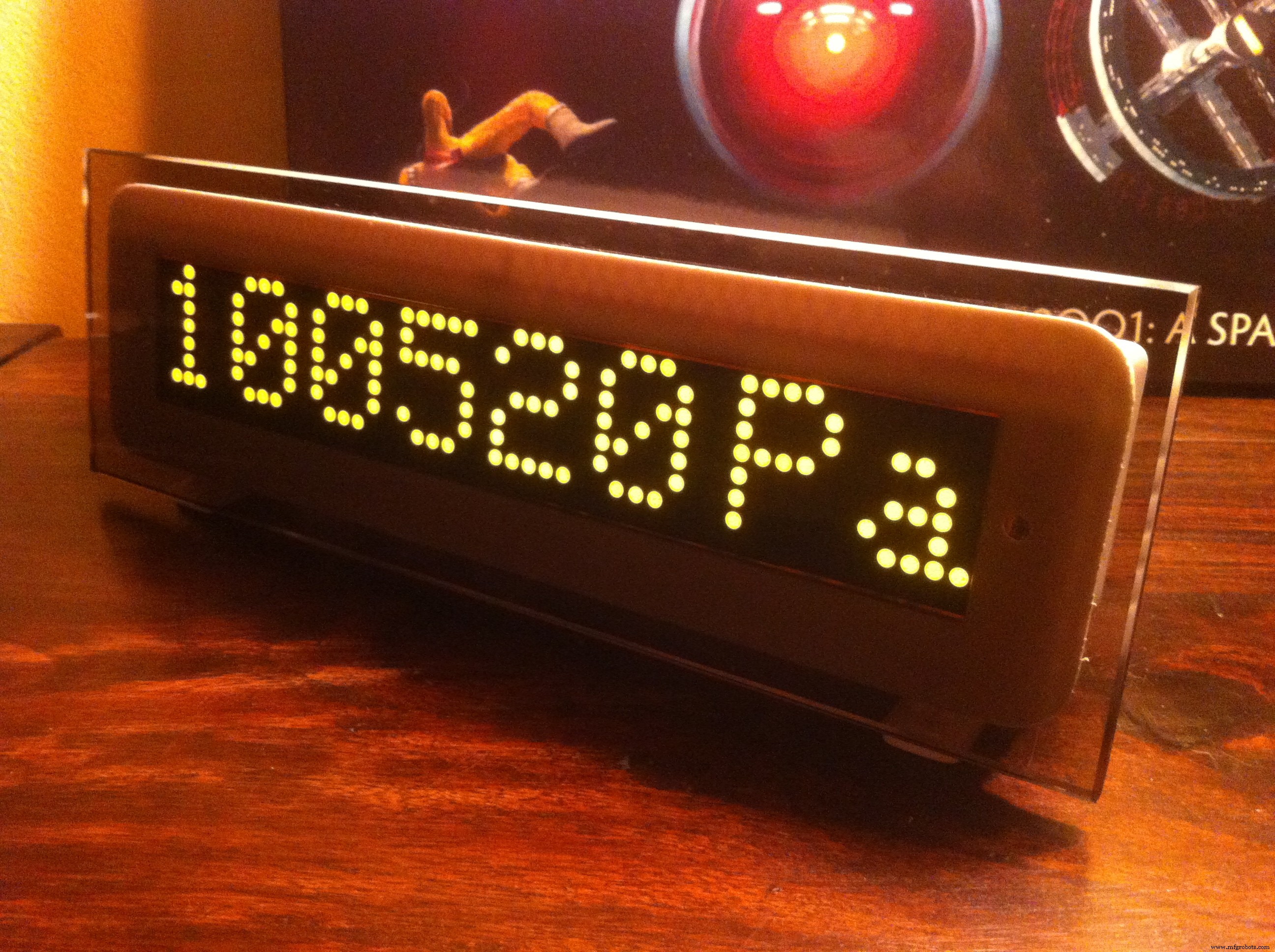
eDOT
IR 원격 수신기와 자동 밝기 조정 기능이 내장된 Arduino 기반 정밀 시계 및 기상 관측소입니다.
이 장치는 WIFI 모듈 등의 추가 하드웨어로 쉽게 확장할 수 있도록 설계되었습니다.
6개의 8x8 도트 매트릭스 LED 디스플레이 덕분에 내부 센서, 맞춤형 스크롤 메시지 또는 인터넷(RSS 등)의 무선에서 오는 다양한 유형의 정보를 표시하는 데 사용할 수 있습니다.
그것은 매우 낮은 전력 소비, 유리 전면과 본체의 3D 인쇄 부품을 결합한 단순하고 우아한 디자인을 가지고 있습니다.
프로젝트는 현재 개발 중이며 업데이트하겠습니다.
Thingiverse에서 3D 부품 다운로드

더 많은 프로젝트를 보려면 내 YouTube 채널도 참조하세요.
https://www.youtube.com/channel/UCbIomyFKzBiLHqEb2xv9GHQ
B.O.M. <울>
eDOTcore PCB
드디어 eDOT용 제어 보드의 첫 프로토타입이 생겼습니다.
eDOTcore 프로젝트 페이지로 이동

<섹션 클래스="섹션 컨테이너 섹션 축소 가능" id="코드">
// eDOT:다목적 정밀 기상 관측소 및 시계//HISTORY// 11/12/2105 측정 보정 계수 추가// 09/06/2016 자동 디스플레이 밝기 추가// 09/06/2016 작업 스케줄러 추가// 2016년 7월 8일 추가된 eDOT 스플래시 화면#include#include #include #include #include #include #include #include "RTClib.h#include Adafruit_BME280 bme; // I2CRTC_DS3231 rtc;int pinCS =10; // CS를 이 핀에 연결하고 DIN을 MOSI에 연결하고 CLK를 SCK에 연결합니다(cf http://arduino.cc/en/Reference/SPI )int numberOfHorizontalDisplays =7;int numberOfVerticalDisplays =1;Max72xxPanel matrix =Max72xxPanel(pinCS, numberOfHorizontalDisplays, numberOfVerticalDisplays);#define 온도 0#define 습도 1#define 압력 2#define 시간 3#define DAY 4#define DATE 5float temp;float tempavg;char tempf[8];float hum;float humavg;char humf[8] float 프레스;float pressavg;char pressf[8];int 화면 =0; // 초기 화면 길이 이전LEDMillis =0; // LED 디스플레이용 updatelong LEDInterval =5000; // 화면 간 지연 int screenMax =5; // screenbool의 최대 수 screenChanged =true; // 화면 상태float lightsens;float screenBrt =0;float lightsensavg;Average avetemp(60); //온도 평균(80개 샘플)Average avehum(60); //습도 평균(샘플 80개)Average avepress(60); //압력에 대한 평균(80개 샘플)Average avelightsens(40); //압력 평균(80개 샘플)//교정 계수float temp_o =-1.70;float temp_s =1.0;float temp_lin;float hum_o =2.45;float hum_s =1.0;float hum_lin;float press_o =0.0;float press_ press_lin;//밝기 센서 보정float brt_o =-4;float brt_s =1.35;스케줄 작업1;스케줄 작업2;void setup() { Task1.start(); Task2.start(); Wire.begin(); // I2C 시작 bme.begin(0x76); matrix.setIntensity(스크린브릿); // 밝기에 0에서 15 사이의 값을 사용합니다. // 필요에 따라 조정합니다. // matrix.setPosition(0, 0, 0); // 첫 번째 디스플레이는 <0, 0>에 있습니다. // matrix.setPosition(1, 1, 0); // 두 번째 디스플레이는 <1, 0>에 있습니다. matrix.setRotation(0, 1); // 디스플레이 방향 조정 matrix.setRotation(1, 1); // 디스플레이 방향 조정 matrix.setRotation(2, 1); // 디스플레이 방향 조정 matrix.setRotation(3, 1); // 디스플레이 방향 조정 matrix.setRotation(4, 1); // 디스플레이 방향 조정 matrix.setRotation(5, 1); // 디스플레이 방향 조정 matrix.setRotation(6, 1); // 디스플레이 방향 조정 matrix.setRotation(7, 1); // 디스플레이 방향 조정/* matrix.setRotation(8, 1); // 디스플레이 방향 조정 matrix.setRotation(9, 1); // 디스플레이 방향 조정*/ rtc.begin();// matrix.setRotation(3, 2); // 마지막 디스플레이에 대한 동일한 유지 // rtc.adjust(DateTime(F(__DATE__), F(__TIME__)));// rtc.adjust(DateTime(2016, 02, 28, 16, 44, 0)); //Serial.begin(9600);//eDOT SPLASHSCREEN matrix.fillScreen(0); 행렬.쓰기(); matrix.setCursor(12,0); matrix.print("eDOT"); for(screenBrt =0; screenBrt <=15; screenBrt++){지연(25); matrix.setIntensity(스크린브릿); // 밝기에 대해 0에서 15 사이의 값을 사용합니다. matrix.write(); }지연(250); for(screenBrt =15; screenBrt>=0; screenBrt--){지연(50); matrix.setIntensity(스크린브릿); // 밝기에 대해 0에서 15 사이의 값을 사용합니다. matrix.write(); }지연(500); matrix.fillScreen(0); matrix.write();delay(1000);}void 루프() { Task1.check(acq1,500); Task2.check(acq2,20);} void acq1(){// 데이터 수집 및 평균 온도 =bme.readTemperature(); avetemp.push(온도); tempavg =avetemp.mean(); 윙윙거리는 소리 =bme.readHumidity(); avehum.push(흠흠); humavg =avehum.mean(); 프레스 =bme.readPressure(); avepress.push(누르기); pressavg =avepress.mean(); 지금 날짜 시간 =rtc.now(); outSec =now.second(); outMin =지금.분(); outHour =now.hour(); 외출 =now.day(); outmonth =now.month(); outyear =now.year() - 2000; 다우 =now.dayOfTheWeek(); } 무효 acq2(){ 조명 감지 =analogRead(A3); avelightsens.push(lightsens); lightsenavg =avelightsens.mean(); screenBrt =제약(((lightsensavg /1023 * 15 ) * brt_s + brt_o), 0, 15); matrix.setIntensity(스크린브릿); // 데이터 선형화 temp_lin =tempavg * temp_s + temp_o; hum_lin =humavg * hum_s + hum_o; press_lin =pressavg * press_s + press_o; 부호 없는 긴 전류LEDMillis =millis(); //Serial.println(screenBrt); if(currentLEDMillis - previousLEDMillis> LEDInterval) // 마지막으로 디스플레이를 변경한 시간을 저장합니다. { previousLEDMillis =currentLEDMillis; 화면++; if (화면> screenMax) 화면 =0; // 사이클이 완료되면 초기 화면으로 재설정 screenChanged =true; }// if (screenChanged) // 화면 변경 시 측정 업데이트// {// screenChanged =false; // 다음 반복을 위해 재설정switch(screen){case TEMPERATURE:dtostrf(temp_lin,4, 2, tempf); // 2개의 소수를 사용하여 5자리로 형식을 지정합니다. matrix.setCursor(6,0); matrix.setTextSize(1); matrix.setTextColor(255); matrix.print(tempf); // 현재 온도를 출력한다. matrix.drawRect(37,0,2,2,255); // 등급 기호를 그립니다. matrix.setCursor(40,0); matrix.print("C"); 행렬.쓰기(); // 디스플레이에 현재 데이터를 기록합니다. matrix.fillScreen(0); // clear displaybreak;case HUMIDITY:dtostrf(hum_lin,4, 2, humf); // 2개의 소수를 사용하여 5자리로 형식을 지정합니다. matrix.setCursor(6,0); matrix.setTextSize(1); matrix.setTextColor(255); matrix.print(흠흠); // 현재 온도를 출력한다. matrix.setCursor(37,0); matrix.print("%"); 행렬.쓰기(); // 디스플레이에 현재 데이터를 기록합니다. matrix.fillScreen(0); // clear displaybreak;case PRESSURE:dtostrf(press_lin,6, 0, pressf); // 2개의 소수를 사용하여 5자리로 포맷합니다. matrix.setCursor(0,0); matrix.setTextSize(1); matrix.setTextColor(255); matrix.print(pressf); // 현재 온도를 출력한다. matrix.setCursor(37,0); matrix.print("파"); 행렬.쓰기(); // 디스플레이에 현재 데이터를 기록합니다. matrix.fillScreen(0); // clear displaybreak;case TIME:// dtostrf(press_lin,6, 0, pressf); // 2개의 소수를 사용하여 5자리로 포맷합니다. matrix.setCursor(0,0); matrix.setTextSize(1); matrix.setTextColor(255); if (outHour <10){ matrix.print("0"); } matrix.print(outHour,0); // 현재 시간을 출력합니다. matrix.print(":"); if (outMin <10){ matrix.print("0"); } matrix.print(outMin,0); // 현재 분을 출력한다. matrix.print(":"); if (outSec <10){ matrix.print("0"); } matrix.print(outSec, 0); // 현재 초를 출력한다. matrix.write(); // 디스플레이에 현재 데이터를 기록합니다. matrix.fillScreen(0); // clear displaybreak;case DATE:// dtostrf(press_lin,6, 0, pressf); // 2개의 소수를 사용하여 5자리로 포맷합니다. matrix.setCursor(0,0); matrix.setTextSize(1); matrix.setTextColor(255); if (outday <10){ matrix.print("0"); } matrix.print(outday,0); // 현재 시간을 출력한다. matrix.print("/"); if (outmonth <10){ matrix.print("0"); } matrix.print(outmonth,0); // 현재 분을 출력한다. matrix.print("/"); matrix.print(outyear,0); // 현재 초를 출력한다. matrix.write(); // 디스플레이에 현재 데이터를 기록합니다. matrix.fillScreen(0); // clear displaybreak;case DAY:// dtostrf(press_lin,6, 0, pressf); // 2개의 소수를 사용하여 5자리로 형식을 지정합니다. matrix.setCursor(15,0); matrix.setTextSize(1); matrix.setTextColor(255); matrix.print(daysOfTheWeek[dow]); 행렬.쓰기(); // 디스플레이에 현재 데이터를 기록합니다. matrix.fillScreen(0); // 디스플레이 브레이크 지우기; } }
제조공정
이 Arduino Tutorial에서는 DS3231 Real Time Clock Module을 사용하는 방법을 배웁니다. 다음 비디오를 보거나 아래에 작성된 튜토리얼을 읽을 수 있습니다. 개요 여기에 오는 첫 번째 질문은 Arduino 자체에 내장된 시간 측정기가 있는 경우 Arduino 프로젝트에 대해 실제로 별도의 RTC가 필요한 이유입니다. 요점은 RTC 모듈이 배터리로 실행되며 마이크로컨트롤러를 다시 프로그래밍하거나 주 전원을 분리하더라도 시간을 추적할 수 있다는 것입니다. DS3231 실시간 시계 DS3231은 시
이 프로젝트에서는 Arduino 터치 스크린 MP3 음악 플레이어와 알람 시계를 만드는 방법을 보여 드리겠습니다. 다음 비디오를 보거나 아래에 작성된 튜토리얼을 읽을 수 있습니다. 개요 홈 화면에는 큰 시계, 날짜 및 온도 정보, 뮤직 플레이어 및 알람 시계용 버튼 2개가 있습니다. 뮤직 플레이어에 들어가면 화면 중앙에 있는 큰 재생 버튼을 눌러 음악 재생을 시작할 수 있습니다. 바로 옆에는 이전 또는 다음 곡을 재생할 수 있는 두 개의 버튼이 더 있습니다. 이 버튼 위에는 노래 진행률 표시줄이 있고 화면 하단에는 볼