

제조공정

산업 제조
고로 부담의 준비 및 충전
고로(BF)는 노로를 제외하고 기본적으로 BF에서 역류 방향으로 이동하는 가스 및 부하 입자의 통로입니다. BF의 안정적인 운전을 위한 기본 요건은 변동이 크지 않은 이동층을 로 내에서 유지하는 것입니다. 구체적으로, 혼합된 버디드 레이어가 없는 안정적인 가스 흐름과 버디드 레이어 구조를 형성하기 위함이다. 이들은 서로 밀접하게 관련되어 있습니다. 가스 흐름의 안정성은 거의 전적으로 부하 충진 구조(입자 크기, 입자 크기 분포 및 미세 입자 비율 등)에 의해 결정되는 부하 투과성과 고체 흐름인 부하 하강 거동에 의존합니다.
원칙적으로 BF 처리는 고체, 기체, 액체 및 분말로 구성된 복잡한 역류, 병류 및/또는 교차 전류, 4상 흐름 시스템입니다. 위상의 상호 작용은 BF의 다른 영역에서 뚜렷하고 국한됩니다. 일반적으로 BF에는 (i) 울퉁불퉁한 영역, (ii) 응집 영역, (iii) 코크스 활성 영역, (iv) 연소 영역(레이스웨이) 및 (v) 데드맨 영역( 난로 센터 지역). BF의 특정 지역에서 부담 단계의 차이와 독특한 상호 작용으로 인해 BF의 전체 볼륨에서 단일 부담 이동 또는 흐름 패턴이 없습니다.
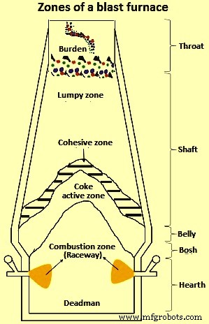
그림 1 용광로 구역
일반적으로 BF에는 4가지 유형의 고체 흐름 영역이 있습니다. 이들은 (i) 응집 또는 용융 영역 바로 위의 위치 및 스톡 라인에서 부하 하강의 균일한 속도와 관련된 플러그 흐름 영역, (ii) 부분적으로 불연속적인 질량인 정체 흐름 영역(dead-man)입니다. 노로 중앙 부분의 반응 코크스 입자, (iii) 부분적으로 반응한 코크스 입자의 느린 움직임이 있는 데드맨에 인접한 부분 정체 흐름 영역 및 (iv) 주변의 수렴 흐름 영역 정체 구역-로 벽 거리 내에서 상당한 입자 속도 변화가 있는 궤도.
부하 하강의 메커니즘은 광석과 코크스의 반응, 용융 및 연소를 통한 소실, 부하층 상단 및 노벽 부근에서 부하 입자의 움직임, 미세 입자 원료가 용광로로 침투하는 과정을 포함합니다. BF에서 부하하강에 영향을 미치는 요인에는 원료의 상태(입자 크기, 강도, 부하 분포 – 광석/코크스 비율), 궤도 상태(보조 연료 분사) 및 로 등이 포함됩니다. 내벽 프로필 등
BF 작업은 프로파일링, 입자 크기 분포 및 성능과 생산성에 영향을 미치는 모든 요소에 매우 민감합니다. BF의 원활한 운영을 위해서는 재고 라인에서 고형 부하 물질(철광석, 코크스 및 플럭스)의 분포를 최적화하는 것이 필수적입니다. 재고 라인 수준에서 부담 분배의 적절한 제어를 통해 BF의 내부 상태를 제어하는 것이 중요합니다.
BF의 부담 물질은 원활한 BF 운영에 필요한 특정 요구 사항을 충족하는 것입니다. 기계적, 화학적 및 열적 요구 사항을 충족하기 위한 것입니다. 충전 물질은 하중을 지탱하고 BF 샤프트의 환원 가스 통과를 허용하는 강력하고 투과성 구조를 형성합니다. 미세 입자의 형성은 샤프트의 환원 가스 흐름을 방해하여 공정 효율을 감소시키기 때문에 부담의 조기 분해를 피해야 합니다. 따라서 BF에서 벌금 부과를 없애야 합니다.
부하의 하향 이동, 화학 반응, 열 프로파일 및 구역의 액체 이동은 생산성을 극대화하고 안정적인 노 작동을 보장하기 위해 최적화되어야 합니다. 원자재의 물리적, 화학적 특성 및 입자 분포의 철저한 제어와 같은 노내 공정과 주변 공정의 최적화를 통해 안정적이고 높은 BF 생산성 운영을 실현할 수 있습니다. 노내공정(장입물체의 물리적 변화 및 화학반응)과 주변부 보조조작(배분비축, 매립, 운송, 저장, 배출, 운반, 장입)은 모두 처리할 수 없는 BF공정의 원활한 기능을 위해 중복되는 기능이다. 연결된 프로세스이기 때문에 격리되어 있습니다.
철광석, 코크스 및 플럭스와 같은 BF 충전 재료는 서로 접촉하는 개별 고체 입자와 유사하기 때문에 벌크 고체로 분류됩니다. 모든 입상 재료와 같은 이러한 재료는 상호 작용하는 입자로 만들어집니다. 일반적으로 이러한 재료의 내부 구조는 상당히 진화적입니다. Tab 1의 벌크 고체 물질 분류에 따르면, BF용 충전 물질은 크게 파손/불연속 고체로 분류됩니다.
| 탭 1 벌크 고체의 크기 분류에 대한 정성적 용어 | |||
| SL 번호 | 크기 범위(mm) | 일반적인 용어 | |
| 구성요소 | 대량 | ||
| 1 | 0.1 미만 | 입자 | 파우더 |
| 2 | 0.1 ~ -1 | 과립 | 입상 고체 |
| 3 | 1 ~ -3 | 곡물 | 깨진 솔리드 |
| 4 | 3 이상 | 덩어리 | 깨진 솔리드 |
일반적으로 모든 형태의 벌크 고형물을 처리하는 것은 균질성을 유지하는 데 어려움이 있습니다. 벌크 고체의 개별 구성 요소와 동일한 물리적 및 화학적 특성을 가진 입자를 고려할 때, 벌크 고체의 혼합(의도적이든 비의도적이든)은 필연적으로 구성 요소의 자연스러운 분할을 초래하는 것으로 나타났습니다. 이 개념은 일반적으로 분리(탈혼합)로 알려져 있습니다. 자연적으로 및/또는 산업적으로, 벌크 고형물의 개별 구성요소 간의 분리는 제품 또는 하위 단위 작업의 의도된 기능에 따라 유리하거나(예:물리적 분리 공정에서) 해로울 수 있습니다(예:혼합 공정).
부담 자재 취급의 이론적 측면
BF 부하 물질은 코크스, 소결체, 펠릿, 보정 괴광석(CLO), 석회석, 백운석, 망간 광석 및 규암으로 구성됩니다. 공정의 특성으로 인해 BF 공정은 본질적으로 부담 재료 크기, 분포 및 강도에 민감합니다. BF에서 부담 물질의 분포는 가스 흐름 위로 이동뿐만 아니라 공정 화학, 공정의 여러 단계 사이의 열 및 물질 전달에 영향을 미칩니다. 재료의 강도는 재료가 내려감에 따라 하중이 증가하기 때문에 매우 중요합니다. 마모 및 파손이 만연한 고온 및 고압에서 발생하는 후속 화학 반응으로 인해 부담의 무결성이 더욱 손상됩니다.
BF 코크스는 부분 용액 반응으로 BF의 노로로 내려가는 유일한 부하 물질이기 때문에 BF 작업 동안 지지 구조 물질 역할을 합니다. 이는 고온 금속(HM) 생산 비용의 높은 비율을 차지합니다. 최근에는 값싼 대체 탄소원으로 코크스를 대체하려는 움직임이 있습니다. 일반적으로 사용되는 대안은 일반적으로 미분탄 주입(PCI)으로 알려진 공정에서 궤도에 석탄을 직접 주입하는 것입니다. 그러나 적절한 코크스가 없는 BF는 부하 투과성 감소로 인해 교체 범위에 이론상 한계가 있습니다. 위치는 로 질식 및 매달림으로 이어지는 위치이며, 이는 추가로 로 슬립 발생을 초래하는 시나리오입니다.
BF 부하의 구성은 용융 온도, 연화 및 일부 환원 매개변수와 같은 노내 공정 변수를 결정하며, 이는 부하 분포가 최적화되지 않은 경우 생산에 부정적인 영향을 미칩니다. 이러한 한계와 도전으로 인해 부담 분배의 적절한 제어가 필요합니다. BF 부담 재료의 일반적인 크기 범위는 표 2에 나와 있습니다.
| 탭 2 BF 하중 재료의 일반적인 크기 범위 | |||
| SL 번호 | 재료 구성요소 | 크기(mm) | |
| 최소 | 최대 | ||
| 1 | BF 콜라 | 25 | 50 |
| 2 | 보정된 덩어리 광석 | 10 | 30 |
| 3 | 소결 | 5 | 30 |
| 4 | 철광석 펠릿 | 8 | 20 |
| 5 | 석회암 | 10 | 40 |
| 6 | 백운석 | 10 | 40 |
| 7 | 망간 광석 | 10 | 40 |
| 8 | 규암 | 10 | 40 |
| 9 | 견과류 콜라 | 10 | 25 |
BF 전하 물질이 포함된 입상류의 물리적 현상과 유동 구조는 처음에는 단순해 보이지만 실제로는 이해하고 예측하기 어려운 복잡한 거동을 보입니다. 이러한 공정의 혼합 및 분리 매개변수에 대한 직접적인 정보의 부족으로 상황은 더욱 복잡해집니다. 그러나 BF 장입재 집합체의 크기와 물질 입도 분포가 크기 때문에 편석 경향이 심각한 운영상의 문제로 최대한 저감이 요구되고 있다.
대량 자재 취급 및 흐름 동작
분말 역학의 요소가 19세기 중반까지 오래 전부터 알려졌음에도 불구하고 벌크 재료의 거동과 흐름에 대한 근본적인 이해는 여전히 불충분합니다. 이는 주로 유동 물리학의 독특하고 복잡한 특성에 기인합니다. 벌크 재료의 취급은 흥미로운 동작을 보여줍니다. 한 측면은 개별 입자 특성으로 인해 입자의 거시적 혼합물이 탈혼합하는 능력입니다. 이러한 관찰은 주로 패턴 발달 및 자기 조직화에 대한 이러한 재료의 자연스러운 경향의 결과입니다. 이 현상은 주로 액체와 같은 특성을 닮은 벌크 재료의 거동에서 기인합니다.
벌크 물질이 유체와 같은 특성을 닮고 그 자체가 고체와 유사하기 때문에 전반적인 거동과 특성은 이러한 일반적인 형태의 물질에서 관찰된 것과 완전히 평행합니다. 일반적으로 역학이 상온의 영향을 받는 다른 형태의 물질과 달리 벌크 재료 역학에서는 그 효과가 무시할 수 있습니다. 유체의 일반적인 혼돈 이류 또는 혼합 효과에 대한 경쟁이 벌크 재료에서 관찰되는 자기 조직화 경향에 대한 책임이 있는 반면 흐름 유도 분리에는 유체 현상이 없다는 것을 아는 것이 도움이 됩니다.
기본 프로세스의 거시적 거동은 주로 미세 입자 간 접촉과 마찰력에 의해 결정됩니다. 5mm보다 큰 BF 충전 재료 크기를 고려할 때 정전기, 반 데르 발스 및 모세관 효과와 같은 표면력의 영향은 무시할 수 있습니다. 또한, 응집 경향은 입자 크기가 10마이크로미터 미만인 초미세 또는 초미세 분말 재료에 일반적이기 때문에 부하 재료의 유동 거동은 비응집성 고체에 해당합니다.
벌크 재료 흐름의 분류
벌크 재료의 흐름은 구성 요소에 따라 분류할 수 있으며 입자 크기, 밀도 및 모양과 같은 물리적 특성이 동일한 입자 그룹으로 정의할 수 있습니다. 유동 구조는 분석하기 어려운 경우가 많으며 외부 여기 및 경계 조건뿐만 아니라 입자 간 상호 작용의 영향을 크게 받습니다. 결과적으로 모든 벌크 재료 흐름 구조를 완전히 설명하는 포괄적이고 일반적인 방법이 없습니다. 입자가 접촉하는 시간의 세그먼트에 따라 몇 가지 다른 유형의 고유한 흐름 구조를 설정할 수 있습니다.
벌크 물질 유동의 경우, 입상 유동은 다양한 수의 준안정 비정상 상태를 나타냅니다. 이러한 준안정 비정상 상태는 진동과 같은 외부 교란이 없는 경우 무기한 지속됩니다. 그러한 상태의 지속은 입자와 경계가 접촉하는 시간의 세그먼트에 크게 의존합니다. 이것은 유체(기체 또는 액체)의 총 부피에 대한 고체 부피 비율에 따라 다릅니다. 그 결과, 입상 물질의 흐름은 일반적으로 고체 부피 분율에 따라 희석 또는 밀집(접촉 지배)으로 분류됩니다. 접촉 시간의 세그먼트에 따라 밀집 흐름은 충돌 지배 또는 접촉 지배로 세분화될 수 있습니다. 이 세 가지 분류에서 행동과 특징적인 흐름은 특정 분류에 따라 다릅니다. 유체-입자 상호작용(예:양력 및 항력)은 묽은 흐름에서 입자 운동을 지배하는 반면 입자 대 입자 또는 입자 대 벽 충돌 또는 연속 입자 대 입자 접촉은 밀집 흐름을 지배합니다.
희석 흐름, 충돌 지배 밀도 흐름 및 접촉 지배 밀도 흐름 간의 벌크 재료 분류의 개략적 표현은 그림 2에 나와 있습니다. 그림 2의 주어진 희석 벌크 재료 분류는 사이클론 분리기, 유동층 및 BF 재료 호퍼에서 관찰할 수 있습니다. 각각 흐름. 밀도가 높은(충돌 및 접촉이 지배적인) 흐름은 배출, 저장 및 운송 과정에서 BF 벌크 재료에 일반적입니다.
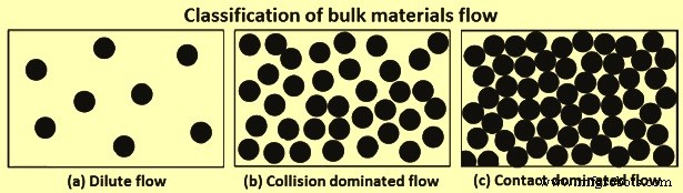
그림 2 대량 재료 흐름의 분류
밀도가 높은 물질 흐름의 두 가지 분류
두 개의 조밀한 흐름 영역의 공유된 특징은 길이와 시간 규모의 함수로서 구조적 진행입니다. 일반적으로 이것은 입자의 재배향으로 인한 패턴 형성으로 이어집니다. 이러한 재료 방향은 중간 규모 구조에 의해 주도됩니다. 미시적 규모로 더 잘 알려진 개별 입자 규모는 중간 규모에 의해 거시적 또는 연속체 규모와 분리됩니다. 세분화된 흐름 어셈블리의 복잡한 입자 상호 작용을 이해하는 것은 분리 또는 탈혼합 현상을 정량화하는 데 중요합니다. 이와 관련하여 기본 미세 구조(이산) 역학에 대한 거시 구조(대량) 거동 간의 관계가 설정되어야 합니다.
충돌이 지배적인 흐름 – 충돌이 지배적인 흐름에서 흐름은 분산되고 흩어지며 에너지가 넘치며 입자는 거의 순간 및 이진 충돌에 의해 주로 상호 작용합니다. 관성 효과는 무시할 수 있습니다. 충돌은 비탄성적이며 입자 대 입자 또는 입자 대 경계 상호 작용 중에 에너지가 소산됩니다. 충돌은 분산적이기 때문에 입상 재료의 '유동성'을 유지하려면 작업 소스가 다소 필요합니다. 충돌의 소산 특성으로 인해 클러스터링 및 밀도파와 같은 독특한 흐름 거동 및 패턴이 관찰됩니다. 밀도파는 입자가 균일하게 흐르지 않고 평균 속도와 다른 속도로 영역으로 이동하는 입자 온도와 관련된 현상입니다.
연락처가 지배적인 흐름 – 접촉이 지배하는 흐름에서 입자 대 입자 충돌은 이분법적이거나 순간적이지 않고 오히려 지속적이고 다중적이며 강한 상관 관계가 있습니다. 이 흐름은 흐름이 가능한 임계 전단 응력과 흐름이 시작될 때 전단 속도에 대한 복잡한 의존성이 있는 두 가지 흥미로운 특성 시나리오를 보여줍니다. 이러한 의존성의 결과로 완전한 흐름 구조는 접촉 지배 흐름과 관련된 점소성 특징을 포함해야 합니다.
다양한 처리 및 국소 회전을 통한 자유도 추가, 확률론적 흐름 규칙의 도입 및 점성 항, 충돌 빈도 및 소산 항과 같은 운동 이론 수송 계수의 수정과 같은 여러 고려 사항을 기반으로 제안된 여러 구성 법칙이 있습니다. 관성 수라는 매개변수가 접촉 지배 흐름의 광범위한 점소성 특성을 재현할 수 있는 강력한 공식으로 보이는 최근 공식입니다. 관성 수는 압력으로 나눈 입자 질량의 제곱근을 곱한 전단 속도입니다.
입상 재료 혼합 및 분리
세분화된 재료 취급은 특히 재료의 크기가 크게 변하는 경우 자연적인 분리(탈혼합) 경향으로 인해 균질성과 균일성 분포가 필요한 경우 매우 복잡합니다. 혼합이 균질성을 촉진하는 유체 공정과 달리, 입상 흐름은 혼합 및 분리 거울상과 유사하며 장기간 혼합 경향은 탈혼합(분리)을 촉진합니다. 이와 같이 반복적인 처리과정을 거치는 BF부하재료의 경우 믹싱을 무소음 특성으로 취급하는 것이 유리하다.
입상 물질의 자연적 질서는 분리되거나 균일한 거동에서 벗어나는 것입니다. 입상 물질이 노출되는 시스템의 상태(충전, 저장, 배출 및 운송)에 따라 분리가 발생하는 다양한 형태의 메커니즘이 있습니다. 분리의 주요 동인은 입자 크기 차이, 밀도 차이뿐만 아니라 마찰 효과, 반발 계수 및 안식각과 같은 미세 특성 차이입니다. 이러한 동인 중 입자 크기는 입상 입자의 분리 거동을 결정하는 가장 중요한 요소인 것 같습니다.
입상 물질 분리 메커니즘
편석을 최소화하기 위한 연구에서, 입상 물질 편석의 13가지 메커니즘이 제안되었다. 그러나 이러한 메커니즘의 대부분은 특수하거나 다른 메커니즘과 중복되는 경우입니다. 이를 고려하여 유연성을 갖도록 분류 입상 물질 분리를 5가지 주요 메커니즘으로 단순화했습니다. 이러한 단순화된 5가지 메커니즘에서 유동화 및 응집 분리 메커니즘은 각각 미세 및 응집 입자를 나타내며 BF 충전 물질에는 적용되지 않습니다. 이와 같이 BF 충전 물질 충전, 저장, 방전 및 운송에 적용할 수 있는 나머지 세 가지 주요 분리 메커니즘은 아래에 설명되어 있습니다.
침투 또는 동적 체질 메커니즘 – 크기 분포 범위가 있는 입자가 상호 작용하게 되면(예:재료 저장 용기에서) 작은 입자가 침투하고 큰 분수 틈새를 통해 아래쪽으로 체질하면서 자발적인 압밀 물방울이 발생할 수 있습니다. 자연스럽게 입상 물질이 흐르면 입상 간극이 벌어지고, 이 때 틈이 생긴다. 작은 입자는 큰 입자 아래의 작은 틈새로 압착될 수 있지만 그 반대는 훨씬 덜 발생하여 작은 입자의 순 분리 플럭스가 자유 표면에서 멀리 아래쪽으로 발생합니다. 이 작업을 일반적으로 침투라고 합니다. 정상 상태에서 입자는 미세한 입자가 많은 바닥층과 분리됩니다. 침투 메커니즘은 그림 3에 나와 있습니다. 입자 직경이 d1 및 d2인 이원 시스템에서 d2가 d1보다 크면 d1/d2가 0.1547보다 작거나 같을 때 자발적 체질이 발생합니다. 이 임계 비율의 첫 번째 사용은 침투 메커니즘을 기반으로 한 슈트 흐름의 입자 크기 차이로 인한 자세한 분리 모델을 유도하기 위해 수행되었습니다.
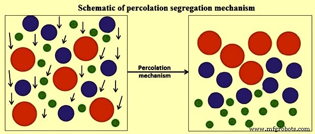
그림 3 침투 분리 메커니즘의 개략도
큰 크기의 진동 스크린과 같은 진동 운동을 통한 전단 유도 및 고밀도 입자가 상단으로 이동하여 침투 분리 메커니즘이 강화됩니다. 이것은 진동 시스템에서 분리를 위해 기하학적 고려 사항만 필요함을 시사합니다. 간단히 말해서, 침투 분리 메커니즘이 발생하기 위해서는 (i) 체질을 위한 임계 크기 비율, (ii) 작은 입자가 간극을 통과하기 위해 응집성이 없어야 하며, (iii) 세 가지 조건이 주로 충족되어야 합니다. 미세 입자가 다중 틈새로 배향될 확률을 증가시키기에 충분한 변형률 또는 입자 간 움직임의 존재
궤적 메커니즘 – 궤적 구동 분리 메커니즘은 일반적으로 그림 4와 같이 주로 저장 빈에 채우고 저장 호퍼에서 배출하고 컨베이어 벨트 끝에서 배출하는 장입물 이송 지점에서 볼 수 있습니다. 원활한 흐름을 보장하기 위해 흐름 조건을 조사한 연구에서 입상 재료의 경우 재료 분리를 유발하는 마찰 항력이 다르기 때문에 크기가 다른 재료가 다른 속도로 이동한다는 것이 지적되었습니다. 궤적 분리 메커니즘은 유체에 수평으로 투영된 입자를 고려하여 수학적으로 설명되었습니다. 직경이 d인 작은 입자, 밀도 Dp 및 Stokes의 법칙에 의해 지배되는 항력을 고려하면, 초기 투영 속도 Vi를 갖는 입자가 점도 Vf 및 밀도 Df의 유체로 이동한 최대 거리 X, 는 식 X =Dp.Vi.(Dp)2/18 Vf에 주어진 것과 같습니다. 그러나 BF 충전 재료 크기를 고려하고 항력이 무시할 수 있다고 가정할 때 입자의 궤적은 무차원 궤적 방정식으로 주어집니다. 무차원 궤적 방정식은 y/x =tan A – [g/2(cos A)2]입니다. x/Vi, 여기서 x 및 y는 각각 수평 및 수직 공간 좌표이고, A는 경사각, g는 중력 가속도, Vi는 자유 비행에서의 초기 속도입니다. 방정식에서 입자의 궤적은 크기(질량)와 무관하지만 자유 낙하 시작 시 각 개별 입자와 관련된 임의의 속도임을 알 수 있습니다.
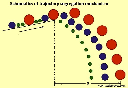
그림 4 궤적 분리 메커니즘의 개략도
미세 속성 차이 메커니즘 – 이 메커니즘에는 (i) 마찰 효과 (ii) 반발 계수 효과 및 (iii) 안식각 효과의 세 가지 효과가 있습니다.
입상 재료에 대한 마찰 효과에 대한 연구는 서로 다른 정지 마찰 계수 F를 갖는 두 가지 구성 요소를 가진 입상 재료가 일반적으로 분리된다는 것을 보여주었습니다. 연구 동안, 높이 h에서 질량 m, 미끄럼 마찰 계수 Fs, 구름 마찰 계수 Fr, 반경 r을 갖는 구형 입자가 다음과 같이 경사각 A를 갖는 경사면 위로 방출되는 경우가 고려되었습니다. 에너지 보존 원리를 고려하면, 불안정 평형 상태의 입자가 방정식 m.g.sin A.r =mg.cos A. Fr에 주어진 운동량 방정식을 만족한다면. 이 방정식에서 입자 이동 거리 X는 방정식 X =(h/Fs).(Cos A)2.(1-Fs/tan A) 및 X =(r.h/Fr).(cos A)로 얻을 수 있습니다. 2. (1-Fr/r.tan A). 이 두 방정식은 각각 슬라이딩 및 롤링 마찰 계수를 고려하여 파생된 입자 이동 거리를 제공합니다. 이들 방정식으로부터 구름마찰계수를 고려할 때 입자이동거리는 입자직경에 따라 달라지며 이로 인해 편석이 발생함을 알 수 있다. 반대로 슬라이딩 마찰 효과는 입자 크기와 질량의 독립성을 나타냅니다.
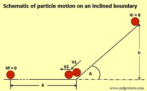
그림 5 경사 경계에서의 입자 운동 도식
반발 계수 효과의 메커니즘은 원칙적으로 동적 효과입니다. 입자가 충돌하거나 입자가 시스템 경계에 충돌하면 서로 다른 속도로 튀어나오고 최종 위치는 계면 탄력성에 의해 결정됩니다. 메커니즘의 예는 더미 또는 저장 빈에 입자를 충전하는 것입니다. 힙의 맨 위 지점에 충돌하면 탄력이 거의 없는 입자가 튀어나오지 않고 제자리에 갇힙니다. 반대로, 높은 탄력성을 가진 입자는 반사되어 증착 지점에서 멀리 떨어진 최종 위치를 찾고 힙 주변에 집중될 수 있습니다.
안식각 효과의 경우 입상물을 쌓을 때 편석 메커니즘이 관찰된다. 더미를 쌓을 때 경사각(안식각)이 재료의 종류에 따라 달라지고 입자의 수와 무관함을 알 수 있습니다. 회전 드럼의 안식각에 대한 경계 효과에 대한 연구에서 축 편석은 정적 또는 동적 안식각에 의해 영향을 받는 것으로 지적되었습니다. 안식각 효과는 원칙적으로 입자 크기, 분포, 모양 및 마찰력과 같은 재료 매개변수에 따라 달라지며 효과에 대한 다른 변수가 포함되어 혼합 메커니즘이 됩니다.
입상 물질 분리의 분류
입상 물질의 분리는 고려 중인 공정에 대해 고려된 변수를 기반으로 분류됩니다. 주로 (i) 입자의 물리적 특성(즉, 크기, 밀도 또는 모양 분리), (ii) 에너지 입력(즉, 진동, 중력 또는 전단 분리), (iii) 입자 이동 방향(즉, 수평 , 또는 수직 분리) 및 (iv) 사용된 장비(예:호퍼, 슈트 또는 컨베이어).
그러나 분리가 생성되는 메커니즘으로 더 잘 알려진 자연적 또는 확립된 프로세스가 가장 일반적인 분류 접근 방식인 것으로 보입니다. 분리는 표면 현상으로 널리 간주됩니다. 따라서 관찰된 다른 메커니즘은 표면층 아래의 입자와 무관합니다. 원칙적으로, 메커니즘은 이동하는 표면층 입자의 거동을 고려함으로써만 설명될 수 있습니다. 다양한 유형의 분리에서 원칙적으로 대부분의 경우 전체 분리 메커니즘은 여러 상호 작용 메커니즘의 조합입니다. 예를 들어, 체질 분리는 큰 입자에 비해 작은 입자가 여과되는 원리를 공유하기 때문에 여과 및 변위/이동 분리의 특별한 경우로 간주될 수 있습니다.
분리 정량화
세분화된 물질 흐름에 대한 분리의 메커니즘 및 영향에 대한 이해가 어느 정도 있지만 이 현상으로 인해 발생하는 문제는 적절하게 제한되지만 발생을 방지하는 것에서 분리의 제어로 전환할 필요가 있습니다. 이와 관련하여 특히 반복적인 취급 과정을 거치는 BF 부하 물질의 경우 영향을 완전히 이해하고 제어하기 위해서는 정확한 정성적 및 정량적 분리 측정 방법이 필요합니다. 입자 분포에 대한 완전한 설명은 이러한 상황에서 간단한 작업이 아닙니다. 그러나 노 재고 라인에 정확하게 부담을 주기 위해서는 입상 흐름에서 혼합 및 분리의 정량화와 함께 입자 재료 분포에 대한 지식이 필수적입니다.
분리 측정 지표 – 원칙적으로 분리는 복잡한 입상 재료 흐름의 일부입니다. 또한, 세분화된 흐름의 불투명성은 분리 연구 중에 유용한 데이터를 물리적으로 추출하는 것이 불가능하지는 않더라도 실질적으로 어렵게 만듭니다. 수학적 모델링 시뮬레이션에 이론적 공식을 적절하게 통합하면 이러한 시스템의 세분화된 흐름 혼합 및 분리를 보다 쉽게 특성화할 수 있습니다. 분리의 정량화는 분리를 일으키는 요인과 입자의 운동 방정식 사이의 상호 관계를 완전히 포함하기 때문에 중요한 작업입니다. 그러나, 입상혼합의 질을 측정하기 위한 여러 지표로서 편도의 정량적 척도로 사용될 수 있으며, 일반적으로 통계적 용어나 무차원 수치적 용어로 표현된다. 사용되는 일반적인 혼합 및 분리 메트릭은 단일 구성 요소 시스템만 설명하는 상대 표준 편차(RSD)입니다. 이 RSD 분리 메트릭은 전체 시스템에 대한 혼합의 거시적 혼합 상태를 제공하기 때문에 반사 산업 응용 메트릭입니다.
혼합 및 분리 측정 메트릭은 사용 중인 많은 인덱스의 중추입니다. 혼합 및/또는 분리 지수를 정의하기 위해 집중 표본 및 특정 분산 측정이 사용된다는 점을 이해하는 것이 중요합니다. 정량화는 매우 유익하지만 이러한 특성화의 주요 단점은 발견되지 않은 상태로 남아 있는 입자 대 입자 분포 변동을 무시하면서 측정 영역에 대한 평균을 구한다는 것입니다. 또한, 입상 물질의 혼합 및 편석에 대해 개발된 고전적이고 기본적인 개념에서 입상 편석의 과정을 표면 현상으로 정의하고 결론지었습니다.
여러 연구에서 다양한 형태의 취급 장비, 작동 방식 및 재료 특성이 재료의 혼합 및 분리 거동과 관련될 수 있음을 보여주고 입증했습니다. 여전히 남아 있는 주요 과제는 혼합 역학을 설명할 뿐만 아니라 본질적으로 더 복잡한 분리 현상을 해결하는 통합 특성화 방법론을 갖는 것입니다. 새로운 접근 방식은 시간과 공간에서 혼합 및 분리의 정도를 알려주기 위해 충전 시스템 내의 원료에서 입자 대 입자 관계의 진화를 특성화하는 것입니다. 이 방법의 중심은 입자와 가장 가까운 이웃 간의 관계의 일부 측면을 사용하여 진화하는 입자 역학 프로세스에 대한 유용한 통찰력을 추론할 수 있다는 아이디어에 기반을 두고 있습니다.
세립형 유동 기계적 분리 모델
분리 역학은 광범위하고 일반적으로 수학적 통계 및 확률 프레임워크로 구성됩니다. The apparent limitation to this approach is that the absolute reflection of the physical nature of the process is precluded coupled with the failure to prescribe the direction in which segregation is taking place. This limits the possibility of a generalization since the knowledge is quite empirical. In the first pioneering study to develop mechanistic models which incorporate all the physics surrounding the prevalent de-mixing tendencies that occur in real granular flow system, the application of kinetic theories for mixtures of granular materials has been applied to study segregation tendencies based on percolation mechanism. Using a combination of statistical and dimensional analysis, the developed formulations hold for negligible enduring frictional contacts with shear rates sufficiently high so that the dominant contributions to the total stresses are due to particle to -particle and particle to boundary collisions. In this study, it has been observed that in a chute flow with high solids volume fractions, there is a high probability of small voids formation relative to big ones. The resulting effect of such a postulation is that small particles sieves through and collects at the base of the bed. This results in a net segregation flux in a direction normal to the chute surface of the small particles.
In as much as the mechanistic models described above give some intended physical appreciation in segregation description, evaluation of key fundamentals such as dispersion coefficients of such granular flows are not small and cannot be established by the above models. In this direction, one study suggested mixed statistical and mechanical interactions based on the kinetic theory of dense gas systems since they give a general understanding of causes of granular flow segregation.
Clustering occurs as granular flow experiences damping as energy is lost after collisions. The change in velocity and movement is non-uniform hence the clusters are formed. Hence, constitutive equations have been proposed based on a kinetic theory for collisional rapid flows. The utilization of the kinetic theory expressions for the analysis of granular segregation shows that it can be used only for inelastic and different sized particles at low volume fractions. This is a limitation as typical granular flow systems are contact-dominated flows with high solids volume fractions. The application of the theory is more useful in case there are established constitutive equations for inelastic, different sized particles and high solids volume fractions.
It is seen that the granular flow resembles mixing and segregation mirror image in which the prolonged mixing tendency promotes segregation. The concentration gradients results in mixing whereas the individual contributions of pressure and temperature gradients produce segregation in granular flow systems characterized by particles with particle size range distributions and material density differences.
The theoretical aspects of the bulk handling of the materials have given a general but compact back ground on granular flow, free surface segregation, mechanisms and theoretical approaches in granular material processes. BF burden material storage, handling and transportation processes are susceptible to the fate associated with segregation. For example, the BF sinter material is known to have more in-bin size segregation and more out of bin size variation than the BF coke.
BF charging system
The charging system of the BF iron-making process can generally be described as a network of equipment and mechanisms designed to charge materials into the BF in a certain sequence, quantity and at a rate which ensure that the specified furnace productivity and prescribed stock-line level is maintained. The charging system consists of three sub-systems which are essentially responsible for (i) batching (ii) transportation, and (iii) charging into the furnace respectively. Batching is done in the stock-house which receives the bulk solid feed materials from their various sources (stockpiles, sinter plant, and coke ovens), storing each material in individual bins to provide several hours of feed material for usual BF operations. The batching process includes screens, weigh-hoppers, conveyor belts, feeders and control systems to prepare batches of charge materials. Transportation provides the means for the delivery of the materials to the top of the furnace. Normally, this is done with either by the belt conveyor system or the skip hoist arrangement. The third sub-system consists of a network of equipment and mechanisms for the charging and control equipment. The overall charging system is interconnected and controlled by an automated charge programme.
Under some conditions, furnace productivity can be limited due to the capacity of the batching (stock-house) process to deliver charge materials. This occurrence is mainly due to transient charge materials flow, equipment settings and charge requirement (burden ratios). A typical source of transient change in charge composition is caused by changes in materials delivered to the stock-house bins and is usually referred to as ‘stock transitions’. This normally occurs when the reclaimed material is used such as the substitution of fresh coke and sinter with stored coke and stored sinter respectively. Such reclaimed materials are known to alter furnace performance compared with the fresh materials. Hence, there is need and usefulness of knowing the different materials and to have their accurate tracking through the charging system so that burdening and blast parameters can be controlled optimally to maintain furnace operational stability.
One other important feature of the charging system is the mixing and segregation of charge material. For example, accurate weighing of several materials in the same hopper requires sequential delivery of the material. However, when the weigh hopper discharges, the materials inherently intermingle to some extent, yielding a time-varying composition of the delivered stream. It is imperative to have an accuracy of time-varying composition in order to estimate the radial variation in burden chemistry and physical properties of the material delivered to the furnace.
Since the burden materials undergo multi-stage handling, hence the processing of different types of charge materials need greater control for high productivity and stable operation of the BF. Also, charge material batching and transportation phenomena are required to be the key focus area for BF operator. For smooth BF operation, the operator is to be position to accurately track the burden materials upto their delivery to the furnace charging system.
The overall charging system is interconnected and controlled by an automated charge program which is coordinated by discrete event processes. Previously, BFs were generally small compared to the modern-day large capacity BFs. In small furnaces, the theoretical amount of coke was normally determined as the controlling charging factor as such, with skip charged furnaces, the optimum charging capacity is reached with full skips of coke.
In the modern BF operations, over and above the need to cope with burden material requirements of larger BF capacity, there are two additional operational factors which are (i) sustenance, and (ii) environmentally friendly operations. Sustenance is mainly through the realization of high furnace productivity which currently has been achieved by an array of technology uses. With this added dimension, the total skip weight is now normally the controlling charging factor and thus modern furnace can work with full skips of iron-bearing burden component. Considering the large size of the present day BFs, the required skip capacities become extremely large and as a result, the design and installation of such skip charging facility to cater for such a huge continuously charging system pose a challenge. Such commensuration of modern large furnaces can only be achieved with sufficient burden delivery capacity. As a result, the modern furnaces are equipped with the conveyor belts charging system. The modern BFs charging facilities consist of a stock-house with a conveyor belt transportation of burden materials to the BF bell-less top (BLT) charging system.
BLT charging system
The charge material is conveyed to the BLT charging system where it is eventually charged into BF top material hoppers (bins) which are alternately used. While one hopper is being filled, the other one is being discharged. The operation of weigh-hoppers and material hoppers is essentially the same and thus, the further description gives an account of particle behaviour during conveyance (conveyor belt), intermediate storage (material bins and weigh hoppers) and eventual discharge (chute or free fall).
Conveyor belt particles behaviour – It is seen that the granular material of varying size fractions and density cause segregation. The detailed phenomenon of the transport mechanism of granular material on a conveyor belt remains limited. However, segregation phenomena on a conveying system are difficult to explain without elaborate simplification of the problem. The system under study has to be defined in terms of mass flow rate and the conveyor speed which promote particle bed development. Operative mechanism of segregation can be established only if the system is well defined. In Fig 6, a schematic representation of the particle size segregation at the transfer point of a moving conveyor belt is shown.
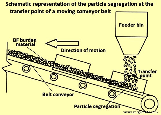
Fig 6 Schematic representation of the particle segregation at the transfer point of a moving conveyor belt
It has been established that there are four main mechanisms to be considered in conveyor belt material movement segregation namely (i) percolation, (ii) particle migration, (iii) trajectory, and (iv) free surface segregation.
Material bins and weigh-hoppers particles behaviour
Granular material bins and weigh hoppers are often used for storage and eventual discharge of material to the subsequent process step. They both in principle have (i) a form of defined material feeding or filling mechanism, (ii) some retention time of material, and (iii) a defined discharge region below. All the three steps have a contribution to the overall material flow behaviour at discharge. Physical and numerical simulations have been done to clarify the relevant information about particle segregation in different kind of hoppers namely cylindrical, bins, conical, and wedge-shaped. The desirable operation is a proportionate outflow from these devices. However, since the flow is gravity induced, the outflow is not easily controlled and there are an inherent induced shear and dynamic effects which cause segregation.
The main prevalent mechanisms of segregation in material storage bins and hoppers are free surface (during feeding), percolation (during retention) and trajectory (during discharging). There is also the importance of particle size and boundary geometry dimensions during the emptying and discharge phases.
In a study to investigate how the internal angle of hoppers affect the granular flow, it has been identified some significant hindrance to free-flow for cohesion-less solids using digital particle image velocimetry (PIV) measurements. As a rule of thumb, to avoid mechanical arching (particle interlocking), the ratio Do/dp (max) is to be satisfied in the range of 5 to 10. Here Do is the boundary outlet diameter and dp (max) is a suitable maximum particle diameter. The ratio is the dimensionless characteristic scale number and it is mostly influenced by the angle of repose as well as the particle size distribution of the material.
In another study, it has been suggested that at least eight elements are to fit across the total width of any granular material handling devices in order to capture accurately the material flow rheology. This means that the diameter of the largest particle fractions in physical or theoretical experimentation is to be at most an eighth the width of a hopper, conveyor belt or any other granular material handling device outlet.
Chute flow particles behaviour
Granular material chute flow is a common feature of stock-house and BLT charging system. With the BLT charging system which comprises of the charge receiving system, material hoppers and rotating chute (distributor), chute flow has assumed additional importance. However, the core principles of the chute flow in the BF top charging system are the same as the one in the stock-house.
Chute flow can be characterized by defining three steps which are (i) burden movement before the chute, (ii) on the chute, and (iii) after the chute, as shown schematically in Fig 7. These three steps constitute three different flow classifications and as such, different considerations need to be employed to study the flow behaviour in this system. When considering burden movement before the chute, any particle collisions in this region can be ignored due to the dilute nature of the flow. When burden material is on the chute, a mathematical description can be used with velocity component along the chute being used as the initial velocity of the material flow. At the chute tip, the trajectory of the materials determines the impact point which in turn the final scatter and distribution of the material in the subsequent handling boundary/ equipment. It is possible that the mechanisms of segregation postulated for conveyor belts systems also apply to chute flow as such and segregation shown schematically in Fig 7 is possible. Three flow streams can be identified with the core flow sandwiched between lower and surface flow. At this stage, the main force considered is gravity.
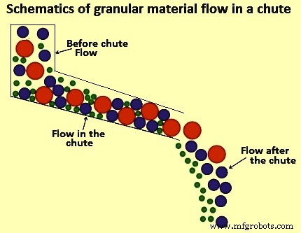
Fig 7 Schematic of granular material flow in a chute
The knowledge of segregation associated with charge material is useful for understanding the charge proportioning in addressing one of the aspects of BF process intensification. However, process intensification in BF processing requires an optimized charging system capacity as BF productivity can be limited by the capacity of stock-house to supply the charge. There is a need to address and optimize multiple-handling operation stages in the product chain.
Charging system capacity analysis
The operation of the BF charging system is as critical as the design of the BF. As can be seen in the schematic representation of a typical modern BF charging system equipped with a conveyor belt delivery system in Fig 8, the material flow sequence is quite complex.
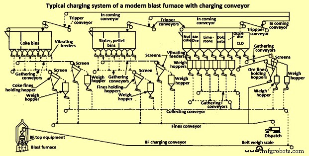
Fig 8 Typical charging system of a modern blast furnace with charging conveyor
In the interest of high productivity, the design of a BF charging system require attention to operating flexibility, availability of extra charging capability, high screening efficiency as well as a limited number of filling, discharge and transfer operations as these cause segregation problems. One important route to increase the efficiency of the BF is full utilization of the charging system capability. Further to this, if the stock-house is not adequately designed and optimal burden delivery is not achieved, the starvation of the BF take place due to the non-availability of the burden materials which consequently results into the loss of BF productivity.
As seen in Fig 8, there are numerous unit operations in a stock-house assembly and all of them have a cascading effect on the overall performance and output delivery to the BLT charging system. In order to understand the macro-behaviour of the burden movement and overall system performance, effective and comprehensive representation of salient system elements and their relationships are to be established. Technically, this involves a description of the various handling steps, materials requirements, duration and sequencing of operations. However, for complex systems such as the stock-house, it is a huge task to clarify all the unit process information. A blend of engineering judgement, experience from similar processes, and reasonable assumptions are used for model development input data and the stock house design.
Modelling of BF charging system optimization
BF charging system involves multiple-handling material movement. The major challenge associated with multiple-handling during materials movement is the timely fulfilling of the requirement and sudden change in the process. Simulations are often used to optimize materials handling systems. Such systems generally use computer-aided process design simulators. These simulators are generally designed to model transient and continuous processes and as such they cannot be used for BF charging system operations which is a batch and semi-continuous process at best. Two available options for modelling batch and semi-continuous processes like BF charging system are spreadsheets (Microsoft Excel) and discrete event simulation (DES).
Spreadsheet models are a common platform that focuses on material balances, equipment sizing and cost analysis. Typically, the development of such a model involves writing an extensive code (in the form of macros and subroutines) in visual basic for applications (VBA) which are incorporated in Microsoft Excel. They are easy to build, much applicable to simple systems but they lack robustness and become unwieldy for large and complex systems. DES is a mathematical/ logical model of a physical system which portrays state changes at precise points in simulated time. Both, the nature of the state change and the time at which the change occurs, mandate precise description. The main feature for a successful DES is an upfront requirement of precise details regarding system and interruptions. Typically, a DES can statistically account for downtime and events. Also, modules can be created and reused while multiple grades or change in process input can be easily handled. Hence, generally the DES-based model is normally used for the BF charging system.
Cyclograms analysis is a modest DES modelling technique which has been often used in BF charging systems for its optimization. The concept evolves on the minimization function of overall start – end sequence (delivery time) of a charging cycle. The delivery time is determined by the order of activation of the mechanisms, the duration of their sequence and the length of the intervals between individual operations. It is easy to follow that the minimum cycle duration occurs when the system is devoid of pauses between the operating cycles of individual mechanisms, as well as when the mechanisms are activated in an efficient sequence.
With cyclograms analysis, it is difficult to incorporate real-time changes in system input conditions. Furthermore, the structure of the analysis precludes detailed in-cooperation of micro-system variables such as discharge behaviour and segregation tendency of materials. Due to these weaknesses of the cyclograms analysis, a DES charge material delivery model based on a mathematical/ logical representation is the better choice for the BF stock house optimization
제조공정
용광로 모니터링을 위한 프로브, 기기 및 측정 고로(BF)는 송풍구 레이스웨이에서 스톡 라인으로의 고체 열교환과 핵융합 구역에서 스톡 라인으로의 역류 산소(O2) 교환의 역류 가스의 원리로 작동합니다. 철 재료(철광석, 소결체 및 펠릿), 코크스 및 플럭싱 재료로 구성된 고체 부하 재료는 로 상단에 장입되는 반면 일반적으로 O2가 풍부하고 때로는 보조 연료가 포함된 공기는 근처의 송풍구를 통해 공급됩니다. 용광로 바닥. 용광로에서 철 함유 물질의 일반적인 체류 시간은 최대 8시간인 반면 가스의 체류 시간은 몇 초입니다. 그러나
고로의 제철 이해 및 일본의 해부 연구 고로(BF) 제철은 주로 잘 정립되고 입증된 성능, 유연한 원료 사용 및 높은 열 에너지 보존 능력으로 인해 용선(HM)을 생산하는 가장 실용적인 수단입니다. BF 제철의 시작에 대한 정확한 날짜는 없습니다. 그러나 중요한 공정 설계와 재설계는 14세기부터 유럽의 제철로에서 구현되기 시작했습니다. 그 이후로 BF 루트는 다른 대체 철 생산 방법보다 선호하는 프로세스로 우세했습니다. 처음부터 BF 제철 공정은 지속 가능하고 실행 가능한 상태를 유지하기 위해 매우 효율적인 공정이 되기 위해