

제조공정

산업 제조
고로의 제철 이해 및 일본의 해부 연구
고로(BF) 제철은 주로 잘 정립되고 입증된 성능, 유연한 원료 사용 및 높은 열 에너지 보존 능력으로 인해 용선(HM)을 생산하는 가장 실용적인 수단입니다. BF 제철의 시작에 대한 정확한 날짜는 없습니다. 그러나 중요한 공정 설계와 재설계는 14세기부터 유럽의 제철로에서 구현되기 시작했습니다. 그 이후로 BF 루트는 다른 대체 철 생산 방법보다 선호하는 프로세스로 우세했습니다.
처음부터 BF 제철 공정은 지속 가능하고 실행 가능한 상태를 유지하기 위해 매우 효율적인 공정이 되기 위해 지속적인 발전을 거듭해 왔습니다. 현재까지 가장 중요한 개발에는 (i) 시설 현대화, (ii) 용광로 생산성 증가, (iii) 코크스 비율 감소, (iv) 용광로 캠페인 수명 연장, (v) 재료 유연성 및 개선이 포함됩니다. 경제성, 효율성을 개선하고 공정을 친환경적으로 만들기 위해 수행된 기술 발전에는 (i) 다양한 공정 관리 및 제어 관행, (ii) 중앙 코크스 장입, (iii) 고로 상부 압력 작업, (iv)가 포함됩니다. ) 산소(O2) 농축을 통한 용광로 작동, (v) 값비싼 코크스를 미분탄, 천연 가스, 오일 및 플라스틱과 같은 대체 보충 탄소원으로 대체 및 (vi) 더 많은 것. BF 제철 공정의 기술 발전은 많은 연료를 소비하는 소규모 생산 단위에서 여러 국가에서 하루에 10,000톤의 HM을 생산하도록 설계된 용광로가 상당히 일반적인 현재 상태에 이르게 했습니다. BF의 크기와 생산량이 이렇게 극적으로 증가했음에도 불구하고 용광로 내에서 발생하는 많은 반응은 아직 알려져 있지 않습니다.
현대식 BF는 주로 소결체, 펠렛, 소결체/크기 철광석 또는 소결체/펠렛 부하에서 작동합니다. 이러한 재료의 유형과 품질은 개별 공장 운영 철학에 따라 다르므로 이러한 재료의 생산 및 감소 특성은 BF 공정에서 가장 중요합니다.
BF 프로세스 개발
BF 프로세스에서 발생한 개발은 점진적으로 도입되어 마침내 표준 운영 관행이 되었습니다. (i) 준비된 짐의 효과적인 사용, (ii) 분사기 분사, (ii) 높은 상단 압력, (iv) 높은 분사 온도, (v) 향상된 제어로 구성된 대략적인 시간순으로 주요 발전을 나열하는 것이 가능합니다. 부담 분배의. 이러한 발전과 동시에 BF의 물리적 크기가 점진적으로 증가했습니다.
준비된 짐 사용
담체 재료의 첫 번째 준비는 로에 장입되는 철광석의 크기를 결정하는 것이었습니다. 부담의 크기를 좁히면 용광로의 투과성이 향상되어 더 많은 바람이 불게 되어 BF의 출력이 증가합니다. 또한 더 큰 광석 덩어리를 제거하여 코크스 비율을 낮추기 때문에 환원 반응의 효율성도 증가했습니다.
장입 전에 철광석을 소결하는 것은 분체 준비에서 두 번째로 중요한 단계이지만 소결은 원래 BF 연도 먼지, 밀 스케일 및 광석 미분과 같은 폐철 함유 물질을 사용 가능한 BF 공급물로 만들기 위해 개발되었습니다. 그러나 이 개념은 1950년대 중반 self-fluxing sinter의 성공 이후 급격히 변화하여 Flux가 BF 전하 부담에서 제거되고 소결을 통해 도입될 수 있게 되었습니다. 이것은 또한 BF 생산성을 증가시키면서 코크스 비율을 감소시켰습니다. 현재 상황은 소결이 이제 현대 BF 공장에서 확립된 부담 요소이며 특성을 더욱 개선하기 위해 계속해서 조사되고 있다는 것입니다.
쉽게 구할 수 있는 고급 철광석이 고갈되면서 공급업체는 선광을 통해 제품을 업그레이드한 후 정광에서 고급 철광석 펠릿을 생산해야 했습니다. 이 공정은 철 함량이 높고 맥석 함량이 낮은 BF 용광로에 부담을 주는 결과로 널리 수용되었으며, 이는 다시 코크스 비율의 하락과 함께 생산량의 추가 증가로 이어졌습니다. 펠릿에 대해 주장되는 또 다른 개선 사항은 더 가까운 크기로 인해 부담의 투과성이 증가했다는 것입니다. 그러나 펠릿의 사용은 보편적이지 않으며 여러 국가에서 BF는 전체 충전량의 작은 부분을 차지하는 펠릿 및/또는 크기의 철광석과 함께 주로 소결 부하로 운영되고 있습니다. 실제로 소결체는 펠릿이 쉽게 구르며 분포 제어가 어렵기 때문에 고온이 우수하고 분포 특성이 우수하기 때문에 대형 BF의 안정적인 작동을 위해 높은 소결율이 필수적이라는 일부 견해가 있습니다. 또한 BF에서 소결을 사용하기 때문에 코크스로 공장에서 발생하는 코크스 바람은 제철소 내에서 소비됩니다.
폭발 주사제
일반적으로 BF에서 사용되는 세 가지 주입기가 있습니다. 이들은 (i) 증기, (ii) O2 및 (iii) 보조 연료입니다. 인젝터는 화염 온도, 즉 풍구 연소 구역의 화염 온도에 영향을 줍니다. 증기와 보조 연료는 화염 온도를 낮추고 O2는 화염 온도를 높입니다. 이론적인 화염 온도를 계산할 수 있으며 많은 양의 O2 및 보조 연료로 원활한 작동을 유지하고 생산성을 높이는 데 매우 중요합니다. 낮은 화염 온도는 퍼니스에서 반응을 방지하고 퍼니스 냉각으로 이어집니다. 화염 온도가 높으면 용융 영역이 확장되고 알칼리 및 실리카(SiO2)의 부담이 증발하여 투자율이 손상될 수 있습니다. 원활한 작동을 위해서는 주입제의 양을 변화시켜 이론적인 화염 온도를 조절하는 것이 필요합니다.
3개의 인젝터를 개별적으로 살펴보면 증기가 코크스와 반응하여 수소(H2)를 생성하여 부하 물질의 감소 정도를 증가시켜 연료비를 감소시킵니다. 보조 연료는 주요 분사 장치입니다. 사용되는 보조 연료의 유형은 현지 조건에 따라 다릅니다. 보조 연료의 주입은 BF에 추가량의 H2와 일산화탄소(CO)를 제공하여 부담의 감소 정도를 증가시키고, 이는 차례로 코크스 비율의 감소를 제공합니다. 불완전 연소는 로 투과성을 손상시켜 로 작동에 부정적인 영향을 줄 수 있으므로 풍구에서 보조 연료의 완전한 연소를 보장하는 것이 필수적입니다. 불충분한 연소는 폭발에 충분한 과잉 O2를 제공하여 제어할 수 있습니다.
산소 주입은 과잉 O2의 양을 증가시키고 화염 온도를 증가시키며, 이는 증기 및 보조 연료의 주입으로 인한 화염 온도의 강하를 상쇄합니다. 또한 bosh 가스의 양을 줄이는 데 유용하므로 BF에서 가스의 채널링 범위와 범람 및 적재 범위를 최소화합니다. 범람으로 인해 노가 불규칙하게 작동합니다. Loading은 기체의 상승으로 인해 용융 슬래그가 하강하지 못하는 상황이다. 궁극적으로 슬래그의 무게는 슬래그가 하강하기 위한 가스 흐름을 극복하기에 충분해야 합니다. 블라스트 내 O2의 비율이 점차 증가하면 HM 1톤당 생성되는 가스의 양이 감소하여 가스에서 샤프트의 고체로의 열 전달량이 감소하여 결과적으로 온도가 감소합니다. 샤프트. 또한, O2 농축을 통한 생산성 향상은 부하 하강 속도를 가속화하여 열 전달 시간을 단축합니다. 그 결과, 충진재가 충분히 예열되지 않은 채 고온 영역으로 들어가고, 이에 따라 노를 냉각시키고 적재물의 미끄러짐 및 매달림을 유발합니다.
분사제를 사용하려면 (i) 기체와 고체 사이의 열전달 한계, (ii) 이론적인 화염 온도 한계, (iii) 보조 연료의 완전 연소 한계라는 세 가지 한계와 관련하여 주의 깊게 제어해야 합니다. 이러한 한계 내에서 제어하면 낮은 연료율과 높은 생산성을 얻을 수 있습니다.
높은 상단 압력
높은 최고 압력의 이점은 용광로의 가스 속도를 감소시켜 가스 환원에 더 많은 시간을 허용하여 연료 속도를 감소시킨다는 것입니다. 더 낮은 가스 속도가 더 거친 먼지 입자를 전달하기에 불충분하기 때문에 먼지 손실도 감소합니다. 또는 더 많은 바람이 불 수 있으므로 용광로에서 동일한 가스 속도를 유지하면서 생산량을 높일 수 있으므로 채널링, 범람 및 적재를 방지할 수 있습니다. 주요 단점은 증가된 가스 압력을 수용하기 위해 스토브에서 버스틀 파이프, 용광로 벽, 용광로 상단 및 가스 청소 공장 등을 통해 BF 장비 전체에 걸쳐 견고한 구조가 필요하며 이는 분명히 비용이 많이 든다는 것입니다. 확실히 BF 상단은 장입 시스템의 가스 압력을 균등화하고 퍼니스 상단 장입 장비의 마모를 방지하기 위해 특별한 설계가 필요합니다. 또 다른 단점은 상부 가스 회수 터빈이 이 에너지의 일부를 회수할 수 있지만 고압 상부 가스의 에너지 손실입니다.
공학적 측면에서 높은 최고 압력을 적용하는 데 문제가 있지만 대형 고로의 작동은 (i) 연료 비율을 낮추고 (ii) 더 높은 생산성을 허용하기 위해 고로를 사용해야 합니다.
높은 폭발 온도
송풍구를 통해 BF로 유입되는 공기는 코크스의 연소에 의해 가열되기 때문에 유입되는 공기가 더 뜨거울수록 송풍구 내부의 추가 가열에 소모되는 코크스는 줄어듭니다. 공기를 예열하는 것은 새로운 일이 아닙니다. 실제로 1세기 전에 BF 스토브가 존재했습니다. 그러나 1300℃를 초과하는 온도에 도달한 것은 비교적 최근의 일입니다. 더 높은 온도의 달성은 스토브 설계의 수정으로 인한 것입니다. 이러한 수정은 (i) 벽돌 모양을 변경하여 체커 작업의 가열된 표면 영역을 늘리고, (ii) 더 높은 온도를 견딜 수 있는 고품질 내화물을 사용하고, (iii) 외부 연소실을 제공하는 것입니다. 가열된 표면적을 증가시킵니다.
부담 분배 개선
가스 이용률을 개선하고 연료비를 낮추기 위해서는 부하 물질의 분포를 제어하는 것이 중요합니다. BF의 응집 영역의 모양을 제어하기 위해 올바른 분배도 필요합니다. 따라서 생산을 최대화하고 BF 벽에서 가스 흐름을 최소화하며 후자는 노의 수명을 연장합니다.
노의 크기가 커짐에 따라 컴파일 각도, 밀도 및 모양의 차이로 인해 BF 내부의 안정적인 가스 분포를 제공하는 데 필요한 부담 물질의 분포를 기존 장입 장비로는 유지할 수 없습니다. 이러한 문제는 충전 벨을 떠날 때 재료의 분배를 제어하기 위해 이동식 갑옷을 설치함으로써 부분적으로 극복되었습니다. 용광로 재고 라인의 모든 위치에 장입물을 정확하게 분배할 수 있는 회전 슈트가 있는 벨리스 상단 및 Gimble 상단 장입 시스템의 개발은 이 문제를 해결하는 데 큰 도움이 되었습니다.
철광석 소결체
많은 BF에서 소결은 BF 부담의 주요 구성 요소입니다. 소결의 화학적 조성은 퍼니스 부하를 구성하는 다른 구성 요소에 따라 달라집니다. 일반적으로 소결의 범위는 플럭스(CaO/SiO2 약 1.2)에서 수퍼 플럭스(CaO/SiO2 약 1.7~2.2)입니다. 플럭스 소결은 일반적으로 용광로 부하의 대부분이 소결일 때 사용됩니다. 수퍼 플럭스 소결은 나머지 부담이 본질적으로 산성일 때 사용되며, 따라서 허용 가능한 슬래그 조성을 제공하기 위해 슬래그 화학의 균형을 맞춥니다. 소결 과정의 특성상 소결이 매우 이질적입니다.
소결 구조 – 철광석과 혼합된 플럭스는 소결 중에 반응하여 용융되어 광석 입자를 공격합니다. 작은 광석 입자의 완전한 응집이 발생할 수 있지만 일반적으로 더 큰 입자는 표면 공격만 받습니다. 냉각하는 동안, 다양한 상의 침전이 슬래그 매트릭스 내에서 발생하며, 전체적인 결과는 평형 상태에서 멀리 떨어져 있는 상과 초기 혼합에서 성분의 분리에 따라 달라지는 불균질 물질의 혼합물입니다. 소결 전에 석회 입자가 존재하는 곳에 석회가 풍부한 영역이 형성됩니다. 전체적으로 존재하는 상은 첨가된 융제의 양에 따라 다릅니다. 자가유속 소결체는 철광석과 석회의 반응으로 생성되는 소량의 칼슘 페라이트와 함께 주로 적철광과 자철광입니다. 여기에서 '페라이트'라는 용어는 염기도와 반응 구역의 광석 입자에 따라 생성될 수 있는 다양한 종의 페라이트의 결합된 양을 나타냅니다. 염기도가 증가할수록 페라이트의 비율이 증가합니다.
소결 시 일반적으로 페라이트는 SiO2와 Al2O3(알루미나)로 오염되며 그 생성물을 SFCA(칼슘과 알루미나의 규소페라이트)라고 합니다. SFCA는 일반적으로 일반식 'n1(Fe2O3).n2(SiO2).n3(Al2O3).5CaO'를 따르며, 여기서 n1,n2 및 n3의 합은 약 12입니다. 칼슘 함량은 약 15에서 상당히 일정합니다. %. 실제로 일반적으로 소결체에서 페라이트는 일반적으로 7 Fe2O3.2SiO2.3Al2O3.5CaO 및 9Fe2O3.2SiO2.0.5Al2O3.5CaO로 발견됩니다.
소결 감소 – 소결에 존재하는 페라이트의 종류와 양은 환원성에 중요한 역할을 합니다. 페라이트의 환원성은 일정하지 않지만 종류에 따라 다릅니다. 소결 염기도가 증가할수록 페라이트의 비율이 증가함을 알 수 있다. 그러나 환원성은 같은 경향을 따르지 않습니다. 1.0 ~ 1.5의 염기도 범위 사이에서 CaO.2Fe2O3 및 CaO.FeO.Fe2O3 유형의 페라이트 증가로 인해 환원성이 증가합니다. 1.4 ~ 1.5의 염기도 범위에서 환원성은 소결에 존재하는 적철광 비율의 감소와 상대적으로 환원 불가능한 2CaO.Fe2O3의 출현과 함께 CaO.2Fe2O3의 소멸로 인해 감소합니다. 1.5 이상의 염기도 증가는 CaO.Fe2O3 및 CaO.FeO.Fe2O3의 출현으로 인해 다시 상승하는 경향을 나타냅니다.
페라이트의 환원 거동은 산화철의 환원이 일어나기 위해 분해된다는 점에서 복잡하다. 환원 과정에서 먼저 산화철이 풍부한 고급 산화철과 페라이트가 환원되어 이칼슘 페라이트와 우스타이트만 남게 됩니다. 그런 다음 가스는 가역 반응 2CaO.Fe2O3 + 3H2 =2CaO + 2Fe + 3H2O에 따라 디칼슘 페라이트를 공격합니다. 방출된 CaO는 가역 반응 2CaO + 3FeO =2CaO.Fe2O3 + Fe에 따라 즉시 우스타이트와 반응합니다. 그런 다음 반응은 이전 방정식 등에 따라 진행됩니다. 그러나 현미경 사진은 Wustite가 가스 경계에 존재하지 않으므로 두 반응 사이에 확산 과정이 발생함을 보여줍니다. 연구에 따르면 산화물 표면에서 di-calcium ferrite가 먼저 환원됩니다. 유리된 철은 산화물 단계에서 분리되고 칼슘은 내부로 확산되어 wustite와 반응하고 다시 철은 분리되거나 Fe3O4로 확산됩니다.
철광석 펠릿
철광석 펠릿의 생산 과정에서 철광석은 유리된 맥석 물질을 분쇄하고 제거하여 선광됩니다. 일반적으로 일부 석영은 펠릿 특성을 개선하기 위해 산성 펠릿 생산에 추가됩니다. 생산된 펠릿의 대부분은 플럭스를 의도적으로 실질적으로 추가하지 않은 산성 유형입니다. 산성 펠릿을 생산하는 동안 녹색 펠릿은 산화성 분위기에서 약 1300℃에서 소성됩니다. 이것은 (i) 적철광 입자의 소결, (ii) 마그네타이트 입자의 산화 및 후속 소결, 및 (iii) 슬래그 결합에 의해 입자의 결합을 촉진합니다. 후자는 그린 펠릿의 충분한 강도를 확보하기 위해 펠릿화하는 과정에서 사용되는 미세한 맥석과 벤토나이트가 융합하여 발생합니다. 이 슬래그 상은 본질적으로 석회, 실리카, 산화 제2철 및 소량의 알칼리, 마그네시아, 알루미나 등으로 구성됩니다.
슬래그 상의 화학 성분 표시는 CaO-SiO2-Fe2O3 상 다이어그램을 참조하여 얻을 수 있습니다. 주목해야 할 점은 대부분의 공정에서 반응이 거의 평형 상태에 있지 않기 때문에 평형 도표를 주의해서 사용해야 하지만 그러한 도표는 유용한 도구라는 것입니다. 소성하는 동안 석영 입자와 적철광 사이에 반응이 거의 일어나지 않으므로 산성 펠릿은 적철광, 석영, 슬래그 상으로 구성되며 경우에 따라 충분한 소성이 일어나지 않은 경우 자철광에서 유래합니다. 펠릿 블렌드의 자철광 광석.
산 펠릿은 노 부하의 일부 BF에서 사용됩니다. 부담에 사용된 금액은 채택된 운영 관행에 따라 다릅니다. 철 단위의 공급원으로서 전적으로 산성 펠릿에서 작동하는 BF의 경우, 슬래그 형성 공정에 필요한 플럭스(석회석 및 백운석)가 부담의 일부로 BF에 충전됩니다.
플럭스 펠릿 – 현재는 플럭스 펠릿의 사용이 선호됩니다. 플럭스 펠릿에서 플럭스는 펠릿에 통합되므로 로에 별도로 장입할 필요가 없습니다. 플럭스 펠릿은 플럭스 또는 백운석과 같이 석회를 첨가하여 생산할 수 있습니다. 플럭스의 첨가와 함께 펠릿의 염기도가 증가함에 따라 미세구조의 변화가 일어난다. 석회 플럭스 펠릿을 고려할 때, 석회의 첨가는 슬래그의 조성과 양, 적철광의 양에도 영향을 미친다. 석회를 첨가하면 석회 농도에 따라 적철광과 석회 사이에 반응하여 칼슘 페라이트 CaO.Fe2O3 또는 2CaO.Fe2O3가 생성될 가능성이 있습니다. 플럭스 펠릿의 경우 소성 온도가 산성 펠릿보다 낮아 과도한 슬래그 형성을 방지합니다.
플럭스 펠릿의 경우 석회에 의한 화학 반응에 의해 칼슘 페라이트로 둘러싸인 적철광 입자가 발견될 것으로 예상된다. 어떤 경우에는 원래의 적철광 입자가 칼슘 페라이트로 완전히 전환될 수 있으며 이는 원래의 적철광 입자 크기에 따라 분명히 다릅니다. 슬래그 단계에 대한 석회의 영향은 두 가지입니다. 첫째, 슬래그의 양이 전반적으로 증가하고 둘째로 염기도의 변화가 있습니다. 정확한 조성은 당연히 반응하는 상의 양에 따라 다르지만 가능성은 CaO-Fe2O3-SiO2 상 다이어그램에서 추측할 수 있습니다. 플럭스 펠릿의 문제 중 하나는 상대적으로 열악한 환원 특성입니다. 석회 플럭스 펠릿의 이러한 단점으로 인해 석회 대신 백운석이 플럭스된 펠릿이 생산되었습니다.
산화철에 마그네시아를 첨가하면 둘 사이의 고체 상태 반응이 일어나고 용융 온도가 증가합니다. 따라서 백운석 플럭스 펠릿에서 마그네시오 페라이트 MgO.Fe2O3 또는 (Mg.Fe)O.Fe2O3가 생성됩니다. 석영은 소성 온도에서 마그네시아와 실리카 사이의 용융이 일어나지 않고 고체 상태에서 일어나는 반응만 일어날 수 있기 때문에 백운석 플럭스 펠릿에서 완전히 흡수될 수 없습니다.
산 펠릿과 관련된 환원 메커니즘은 기체 환원, 반응 역학 및 직접 환원으로 설명할 수 있습니다. 기체 환원의 경우, 산화철에서 O2가 제거됨에 따라 산 펠릿은 적철광에서 자철광으로, 우스타이트(560℃보다 높은 온도에서)에서 금속 철로의 환원 경로를 따릅니다. 이러한 상 변화는 환원제로 CO를 사용하는 가역적 기체 반응으로 표시됩니다. 방정식은 3Fe2O3 + CO =2Fe3O4 + CO2, Fe3O4 + CO =3FeO + CO2, Fe3O4 + 4CO =3Fe + 4CO2, FeO + CO =Fe + CO2입니다.
적철광 환원의 메커니즘은 광범위하게 연구되었으며 적철광의 환원은 개별 단계, 즉 자철광, 그 다음 우스타이트 등으로 발생하지 않지만 환원은 환원이 제공되는 경우 위에서 아래로 화학 구조를 생성합니다. 가스의 포텐셜은 충분히 높습니다. 즉, 구조는 자철광 층으로 둘러싸인 적철광 입자, 그 다음 황철광 및 마지막으로 금속 철의 외부 층으로 구성됩니다. Wustite는 비화학량론적입니다. 즉, 철 이온이 결핍되어 있습니다. 이러한 공석은 산화철 격자를 통한 철의 확산을 가능하게 하기 때문에 산화철의 환원 거동에서 중요한 결함입니다. Wustite에서 O2를 제거하면 산화물 표면의 철 이온 공석이 채워집니다.
표면 환원은 산화물 내부에서 반응 계면 쪽으로 공극과 전자 결함의 확산을 시작합니다. Wustite의 감소와 함께 금속 이온의 내부 흐름은 자철광 층과 반응하여 자철광을 감소시킵니다. 그런 다음 반응이 일어나고 사이클이 반복되어 점차적으로 자철석을 감소시킵니다.
산화철 환원의 역학은 광범위하게 연구되었지만 속도 제어 단계와 관련하여 몇 가지 상충되는 견해가 있습니다. 산화철의 기체 환원 과정은 (i) 벌크 기체 상으로부터 경계층을 통한 반응 기체의 확산, (ii) 생성물 층을 통한 반응 계면으로 기체의 확산, (iii)과 같은 많은 단계를 필요로 합니다. 반응 계면 상의 기체 흡착, (iv) 계면에서의 화학 반응, (v) 반응 계면으로부터 생성물 기체의 탈착, (vi) 반응 계면으로부터 입자 표면으로 기체 반응 생성물의 확산, 및 (vii) 경계층을 통해 벌크 기체상으로 생성 기체의 확산.
속도 제한 단계와 관련하여 큰 충돌이 있지만 일반적으로 산화철의 환원은 McKewan K1 =Kw/do =ro[1 – (1-R1/3)]/t로 유도된 방정식을 따릅니다. 여기서 K1은 속도입니다. 적철광/자철광 경계면의 진행 정도(mm/분), Kw는 속도 상수(g/sq mm/분), do =순수 산화철 구의 밀도(g/cu mm, ro)는 산화철 구의 반경 mm, R은 적철광에서 자철광으로의 전환율이고 t는 반응 시간(분)입니다. 산화철의 환원속도가 이 식에 부합하므로 속도제한 단계는 화학반응이라고 한다.
Hills는 질량 전달 원리를 사용하여 질량 전달 및 확산만으로 제어되는 반응이 화학적으로 제어되는 반응을 식별하는 데 자주 사용되는 특정 특성, 특히 시간에 따른 [1 – (1 – R)1/3)]의 선형성을 가질 수 있음을 보여주었습니다. . Hills는 반응이 (i) 생성물 층을 통한 기체 확산 및 (ii) 입자 외부의 경계층을 통한 수송의 두 과정에 의해 제어된다고 가정했습니다. Hills rate 방정식의 한 형태는 3[1 – (1 – R)2/3]-2R(1- Bm) =C2.t로 표현될 수 있습니다. 여기서 R은 부분 감소, t는 감소 시간(초), Bm =DE/Kg.ro, Bm은 물질 전달을 위한 계수, 즉 제품 층 내부의 확산 저항과 입자 외부의 물질 전달 저항의 비율, DE는 제품 층의 확산 계수(단위:sq mm/sec, Kg)입니다. 는 mm/sec 단위의 반응 구 표면에 대한 물질 전달 계수이고 ro는 mm 단위의 구 반경입니다. C2는 환원 반응에 대한 상수이며 산화철 구 속성 및 환경 조건에 따라 달라집니다.
800℃ 이상의 온도에서 환원하는 경우, 입자의 용융이 일어나지 않는 한, 기체 환원 온도의 상승은 반응 속도의 상승으로 이어진다. 다공성이 증가하면 감소율도 증가합니다.
탄소(C)를 사용한 산화철의 직접 환원 메커니즘은 BF에서 매우 중요하며 직접 환원은 900℃를 초과하는 온도에서만 상당한 양으로 발생한다는 것이 밝혀졌습니다. 직접 환원 반응은 실제로 다음과 같이 나눌 수 있습니다. 방정식 FexOy + C =FexO(y-1) + CO. 기체에 의한 환원은 CO + FexOy =FexO(y-1) + CO2입니다. 이러한 반응에서 x =1, 2 또는 3이고 y =1, 3 또는 4입니다. 용액 손실(Boudouard) 반응 CO2 + C =2CO는 기체 반응을 위해 CO를 제공합니다. 직접 환원 반응은 실제로 간접 환원 반응을 통해 일어나므로 BF 공정에서 고체 산화물의 직접 환원은 반응의 진행과 관련하여 중요하지 않음을 나타냅니다.
액체 산화철이 C와 반응하는 상황은 물론 액체 산화물과 고체 C 사이의 접촉 면적이 고체 산화물과 고체 C의 접촉 면적보다 훨씬 크다는 점에서 상당히 다릅니다. 또한, 액체 내 반응 및 생성물 종의 확산은 다음과 같습니다. 고체 상태보다 훨씬 빠릅니다. 이러한 효과는 고체 산화물/고체 C 시스템보다 액체 산화물/고체 C 시스템에서 훨씬 더 높은 반응 속도를 초래합니다. 반응 온도가 높을수록 환원 정도가 커집니다. FeO 농후 슬래그의 환원을 위한 속도 제한 단계는 환원 정도에 따라 변하는 것으로 밝혀졌다. 환원된 철의 핵형성 및 C/액체 계면에서의 화학 반응은 높은 환원도에 도달할 때까지 속도 제한 단계를 구성하는 것으로 보입니다. 더 높은 환원 수준에서 가장 느린 단계는 슬래그 경계층을 통한 O2의 확산입니다.
환원 시 알칼리의 영향
알칼리는 고온 영역의 기화와 더 차가운 영역의 코크스 및 부하에 대한 후속 침착을 통해 BF 내부를 재순환합니다. 침전된 알칼리는 최종적으로 기화될 부담과 코크스와 함께 하강합니다. 이러한 재순환 효과의 특성은 상당히 높은 수준의 알칼리가 BF 내부에 축적되어 부담 물질의 감소에 영향을 줄 수 있다는 것입니다. 알칼리 첨가는 산 및 염기성 펠릿의 환원율을 증가시키는 것으로 밝혀졌습니다. 알칼리 첨가의 최적 수준이 있으며, 그 이상에서는 광범위한 슬래그 형성으로 인해 환원율이 감소합니다. 또한, 백운석 플럭스 펠릿은 환원성 가스에 알칼리 증기가 있을 때 환원율의 감소를 나타냅니다. 또한, 알칼리 유형의 유형이 중요합니다. 즉, 수산화나트륨(NaOH)은 동일한 농도의 나트륨 양이온에 대해 염화나트륨(NaCl)보다 환원 반응을 더 잘 촉진합니다.
산화철에 알칼리를 첨가할 때 발생하는 환원율의 증가는 팽윤이 증가하여 환원성 가스에 더 큰 표면적이 노출되기 때문이다. 또한 알칼리는 비표면과 관련된 화학적 환원을 유발하는데, 이는 우스타이트의 표면이 금속성 철 층에 의해 보호되는 대신 지속적으로 환원 가스에 노출된다는 것을 의미합니다. 비표면 관련 화학적 환원은 알칼리 양이온이 wustite 격자에 혼입되어 Wustite 활성이 불균질화되어 철의 핵 생성 거동을 수정하여 비표면 관련 화학적 환원으로 이어짐으로써 발생합니다. 펠렛 팽창은 일반적으로 과도한 알칼리 함량의 증상으로 간주됩니다.
BF의 부담 행동
BF 공정의 수명 동안 산화철, 펠렛 및 소결체의 환원 특성에 대한 상당한 지식이 축적되어 약 1000℃의 반응 온도까지 축적되었습니다. 이 이상의 온도에서 발생하는 반응 또는 발생하는 반응에 대해서는 알려진 바가 거의 없습니다. BF 부담 재료의 특성에 미치는 영향. 1000℃까지의 온도에서 부하 물질 거동에 대한 방대한 양의 정보가 있음에도 불구하고 작동 중 BF의 내부 검사가 매우 어렵다는 단순한 이유로 적용하기가 쉽지 않습니다. 작동 중인 BF에서 샘플을 얻기 위한 주요 '도구'는 가스 탐침, 온도 탐침 및 부하 탐침 등입니다. 유용한 범위는 BF의 매우 적은 양에 불과합니다.
그러나 환원 중 물질 거동과 BF 공정 사이의 상관 관계가 합리적으로 확립되었다고 진술하는 것이 공정합니다. 예를 들어, 저온 환원 시 물리적 크기의 파괴가 큰 재료는 실제로 노 투과성을 감소시키고, 환원성이 높은 부하 재료는 연료율을 감소시키는 것으로 알려져 있다. 또한 환원 중에 광범위하게 팽창하는 펠릿은 용광로 투과성의 손실로 이어집니다.
해부 연구
BF 내 재료의 거동에 관한 주요 돌파구는 여러 작동 용광로의 물 담금질과 그 내용물의 체계적인 해부 및 연구와 함께 이루어졌습니다. BF 내부의 부하 분포는 장입 순서, 장입 중량, 부하 구성 요소 및 노 작동에 따라 달라지며 각 노가 다른 방식으로 작동하게 됩니다. 그림 1은 Kukioka BF no.4의 내부 구조를 보여줍니다. 광석 및 코크스 층은 연화-용융 영역 또는 응집 영역에 도달할 때까지 유지됩니다. 해부 절차 중 응집 영역의 시작은 기계적 수단에 의한 재료 제거에 대한 물리적 저항 증가로 확인되었습니다. 응집 영역은 재료가 부드러워지기 시작하여 결국 녹는 곳입니다. 응집 영역이 용해로의 한 영역에 있지 않고 합리적으로 기하학적 모양으로 분포되어 있다는 발견은 작동 중 BF 내에서 발생하는 반응에 대한 주요 통찰력 중 하나였습니다.
용해로 가동에 따라 응집대의 구조가 달라지는 것을 알 수 있었다. 예를 들어, 그림 1은 세 가지 다른 용해로에서 발견되는 구조를 보여줍니다. 히로하타 BF No. 도 1은 '도넛' 형태의 연화된 층을 역 'V' 구조로 배열한 반면, Kukioka BF 4호는 'W' 형태의 응집 영역을 갖는다. Higashida BF no.5는 담금질 작업 이전에 불규칙한 로 작업으로 인해 왜곡된 역 'V'가 나타납니다.
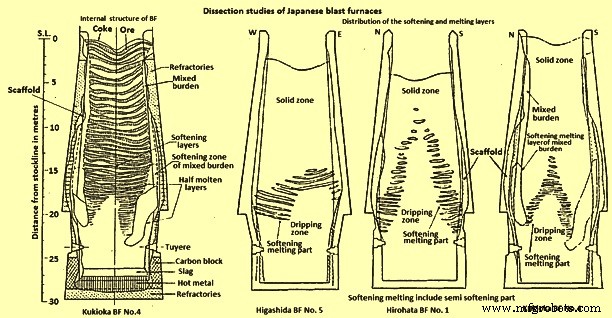
그림 1 일본 용광로의 해부 연구
감소 수준 – Hirohata BF no. 1과 Kukioka BF no.4는 흥미로운 기능을 꺼냈습니다. One of the interesting features is the fact that very little reduction occurs until the burden reaches the cohesive zone, wherein reduction proceeds rapidly. One of the major problems with water quenching is the possible reoxidation of the burden material during the cooling period and laboratory tests were conducted to determine the extent of reoxidation which might be taking place. One study was made to measure the reoxidation of sinter, in the laboratory, under the same cooling conditions existing during quenching of a BF, using a series of different initial reduction levels. The another study used another technique employing burden materials of various reduction degrees cooled from three different temperatures (400 deg C, 800 deg C and 1000 deg C) at a cooling rate of 200 deg C per hour in a nitrogen (N2) atmosphere. In this study it has been found that although the reduction temperatures and reduction degrees were different, the final reoxidation degree was around constant at 20 % to 25 %, i.e. the reoxidation increased in proportion to the initial reduction degree. At temperatures below 300 deg C, no reoxidation occurred. The result of these experiments is that the reduction levels were required to be increased, for example, from 10 % to 30 % to 15 % to 40 %. These corrected levels were in agreement with the reduction levels found in Russian dissection studies on a N2 quenched furnace.
Temperature profiles – The temperature isotherms within the furnaces were estimated by a combination of several methods. In one method, ‘Tempil’ pellets encased in numerous graphite holders were charged prior to blowing out the furnaces. This technique allowed the estimation of the temperature within the range 200 deg C to 1800 deg C, but one of the problems with this technique was that there was no method of controlling the distribution of the graphite holders within the BF. The other methods employed were measurement of the extent of coke graphitization, thus estimating the temperature between 1200 deg C and 1700 deg C. Measurement of the coke electrical resistance, which allowed temperature estimation between 1100 deg C and 1700 deg C and finally the degree of iron ore fusion was measured to estimate temperatures within the range of 900 deg C to 1400 deg C.
Comparing the isotherms with the distribution of the softening-melting burden layers (Fig 1 and Fig 2), it was found that the cohesive zone exists over a temperature range of around 1100 deg C to 1500 deg C for BFs operating mainly on sinter burdens.
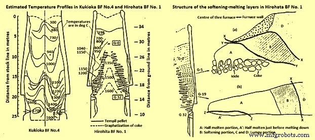
Fig 2 Estimated temperature profiles in Kukioka BF no. 4 and Hirohata BF no. 1 and structural of the softening-melting layers in Hirohata BF no. 1.
Burden layer structure within the cohesive zone – The type of structure of an individual burden layer in the cohesive zone depends upon the position of the layer within the BF. Two layers from Hirohato BF no.1 are shown in Fig 2. Layer G-5 is near the apex of the cohesive zone, while layer G-19 is situated near the base of the cohesive zone. Layer G-5 has four distinct zones, two of which are lumpy or granular portions (C and D). Layer G-19, on the other hand, contains only one lumpy portion, D. Apart from the obvious shape differences between the layers, the other main difference is the replacement of the icicles’ in layer G-5 by a half-molten portion just prior to melting down, A in layer G-19.
As seen earlier a substantial amount of reduction takes place in the cohesive zone and this has been proved by the reduction data obtained for each portion as given in Tab 1, and Tab 2. The figures are on the low side, as reoxidation, caused by the act of water quenching, certainly have taken place. The reason for the high reduction level of portion C is attributed to the slightly lower reduction temperature while in contact with the coke.
| Tab 1 Degree of reduction of the burden materials in the softening-melting layers of Hirohata BF no. 1 | ||||
| Softening-melting layer | Portion* | Reduction degree % | ||
| Sinter | Ore lump | Pellet | ||
| G-5 | A | 65.6 | 65 | 79.3 |
| C | 72.8 | 68.2 | 81.2 | |
| D | 11.5 | 12.3 | 14.6 | |
| G 19 | D | 35.4 | 36.6 | 41.3 |
| * B:Softening portion, C and D:Lumpy portion | ||||
| Tab 2 Degree of reduction of the pellets in the lumpy portion | ||
| Softening-melting layer | Sampling position (distance from the boundary*) (m) | Mean value of the reduction of the sample pellets (%) |
| G3 | 2 | 12.7 |
| 0.2-around 0.3 | 23.1 | |
| G10 | 1 | 14.1 |
| 0.2-around 0.3 | (55)** | |
| G12 | 1.3 | 13.9 |
| 0.9 | 14.3 | |
| 0.5 | 12.3 | |
| * Between the lumpy and softening portions | ||
| ** The value of the reduced pellet being not reoxidized | ||
The thickness of the softening-melting layers in Hirohata BF no. 1 ranged from 400 mm to 500 mm, in the case of the upper layers, to 70 mm – 100 mm for the layers near the base of the cohesive zone. The diminishing thickness is due to compaction, caused by the pressure exerted by the weight of material above the layer and also because of a natural thinning of material due to the increase in furnace diameter as the material descends. In the softening portions iron ore granules were combined in contact with each other. Sinter particles in the layers deformed very little, unlike pellets, which showed signs of deformation.
The process of pellet metallization can take place in one of three modes namely (i) the metallic iron is uniformly distributed within a pellet, (ii) a metallic shell is formed, leaving a wustite core, and (iii) wustite within the pellet reacts to form a slag and moves towards the metallic iron shell, leaving a central cavity. The reason for these three possible modes is not connected with the distribution within the softening-melting layer, but can be due to differences between the pellets or uneven gas flow in the softening-melting layer.
It has been found that the half molten portion consisted of highly compacted metallic iron and a small quantity of slag. Any limestone or olivine present remained unslagged. The icicles extend into the coke voids and consist of a metallic shell with a hollow interior, with small droplets of slag adhering to the iron. The higher the softening-melting layer within the furnace, the greater the length of the icicles, e.g. level G-1 produced some icicles of several hundreds of millimeters in length, while the lower layers produced icicles only 10 to 20 millimeters long.
The structure of the softening-melting layers in Kukioka BF no.4 was basically identical to those described for Hirohata BF no.1, except the thinner burden layers made the structure less distinct and the icicles smaller.
Slag composition changes – The major chemical change of the slag phase in the softening-melting layers is a decrease in the FeO content as the slag trickles down from the melting portion. Although large differences were detected by x-ray microanalyses of slags in portion A, ranging from 2 % to 20 % FeO, depending upon the location, the FeO content of the slag immediately prior to separation from the softening-melting layer was only 2 % to 3 %. The type of slag was not significantly different to that found in the normal sinter product, but in the ore granules a considerable quantity of fayalite was produced. Descent of the slag results in a gradual change in composition. The gradual increase in the CaO/SiO2 ratio is attributed to fluxing with limestone and a drop in the SiO2 content, caused by SiO2 reduction. The rise in Al2O3 is created by the incorporation of coke ash into the descending slag.
Metal composition changes – Considering the changes in metal composition as it descends the furnace; the carbon content of the metal in the half-molten portion of the softening-melting layer is around 0.2 % in the upper part and 0.35 % to 0.57 % in the lower part. The source of C in these half-molten layers is attributed to the carburizing action of the CO, except for the metal in contact with coke. Similar trends are visible in the layers found in Kukioka BF no.4. The rise in the C content of the icicles is attributed to the metal being in direct contact with particles of coke. Two distinct processes have been identified which are operating for the separation of metallic iron from the layers. The first mechanism is via the icicles which form at 1350 deg C to 1400 deg C and drip into the coke bed. Reduction of the iron oxides present in the icicles occurs rapidly to produce metallic iron. The second process occurs in layers in which no icicles form. In this situation, the metallic iron is carburized by the underlying coke until it reaches a C level such that melting can occur at the pertaining temperature. In this case the temperature of meltdown is around 1500 deg C.
The question of the mechanism of silicon pick-up by the metal within the furnace has been the subject of considerable discussion. Studies carried out in the experimental BF at Liege, Belgium fitted with sampling probes have found that the silicon level rise gradually from the melting zone to the hearth, such that 75 % of the final HM silicon is achieved by the time the metal reached the tuyere level. The Japanese dissection studies on the other hand reveal that the silicon level of the metal at the tuyere level is far in excess of that of the tapped HM. An explanation for this discrepancy between the two groups of studies can be that silicon pick-up had occurred during the process of water quenching the Japanese furnaces. During the experiments conducted to determine the probability of silicon pick-up during quenching, it was found that silicon pick-up from any slag present could be a possibility. Hence, this is to be borne in mind when analyzing the Japanese dissection data.
The sulphur (S) level of the metal within the softening-melting region is much higher than the concentration in the tapped HM. In the granular zones very little increase in S level occurs, which can be due to the materials in the softening-melting zone absorbing the S from the ascending gases, rather than a lack of absorption capacity by the burden in the granular zones. The lack of substantial quantities of S in the gas in the stack of the furnace can explain the horizontal profile at temperatures below 800 deg C. Further, as the temperature and slag basicity rise, the distribution of S between the slag and metal increases accordingly. Some idea of how S recirculates within the BF can be seen in Fig 3 in which the circulation of S within Hirohata BF no. 1 is shown.
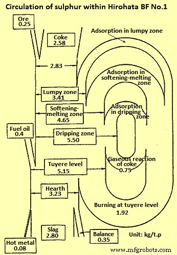
Fig 3 Circulation of sulphur within Hirohata BF no. 1
Size distribution – The change in physical size of the burden components during their descent was determined from the quenched furnace data and one of the major problems with this part of the study was that breakdown of material occurs during the quenching operation. Degradation of sinter reaches a maximum at temperatures of 400 deg C to 600 deg C and increases with the retention time. At levels of reduction in excess of 30 %, very little degradation occurs. Estimation of the cooling pattern of Kokura BF no.2 shows that the burden materials are exposed for a lengthy period of time to conditions which lead to considerable breakdown. The effect of the water quenching operation on the degradation of sinter was calculated. This calculation indicates that the sinter degradation increases with time after blow out and considerable degradation occurs in the region around the middle of the shaft.
Applying this to a centre working furnace (centre working means that the majority of the gas flows up the central axis of the furnace), it has been noticed that the degradation of sinter in the central zone of the furnace, where the reduction degree is high, is mainly caused by the reduction processes during operation. The situation in the peripheral zone is that the reduction degree is low and in this situation the breakdown is mainly caused by the long residence time of materials around 500 deg C during blowing out of the furnace. This was illustrated with the dissection results for the centre working Hirohata BF no.1. Another factor in maintaining the size of the burden materials is that in the central region of Hirohata BF no. 1, cracks if generated fused immediately because of the high temperatures and the rapid reduction taking place. Degradation is generally a problem having maximum concerns with sinters. Examination of the size distribution of pellets revealed that they were hardly pulverized and maintained their original shape.
Influence of gas flow – To further prove that the determination of the shape of the cohesive zone is by the gas flow within the furnace, core samples were taken from the Hirohata BF no.1 and Kukioka BF no.4 and their permeability was determined. Then their permeability was related to gas flow and gas velocity distribution profiles were prepared. These profiles can be directly related to the softening-melting layer distribution. The gas flow in the lower part of the BF is fast, 7 m/sec to 9 m/sec but slows considerably in the softening-melting layers to 2 m/sec to 4 m/sec thus indicating the poor permeability of the softening-melting layers. As the gas ascends the shaft its velocity naturally decreases due to the drop in gas temperature.
Cohesive zone control
It has been shown that the shape of the cohesive zone varies from BF to BF and much attention needs to be given for its control. The control of the cohesive zone is very dependent upon burden distribution. For maximum production, at the expense of fuel rate, a strong centre working profile is to be adopted, but if the fuel rate is to be minimized, then a less centre working practice is to be followed. Indeed, this is very much visible when comparing a strong centre working furnace, like Hirohata BF no.1 with moderate centre working furnace, like Kukioka BF no. 4. This point can be well explained by relating productivity to the height of the cohesive zone above the tuyeres (Fig 4). The higher the position of cohesive zone in the furnace, the greater is the productivity, although at the expense of an increase in fuel rate.
Another point concerning control of the cohesive zone is its effect on the refractory lining. If the wall temperature of the furnace is too high, then refractory wear is appreciable and one can expect a reduced life of the BF. Thus, for maintaining the refractory thickness, it is necessary to control the cohesive zone so that the wall temperatures are maintained at minimum levels.
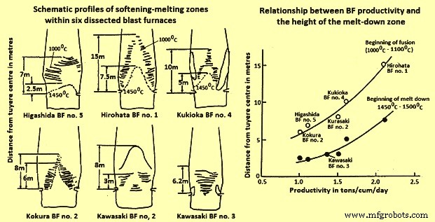
Fig 4 Schematic profiles of softening-melting zones and relationship BF productivity and height of the melt-down zone
Melting processes
The role of S in the melting process is governed by the Fe-S-O phase diagram. There is a necessity of a reaction between solid metallic iron and wustite in the burden with gaseous S, in the ascending gases. These phases react to form a eutectic of chemical composition 24 % S, 9 % O2, and 67 % Fe, having a melting point of 915 deg C. Once formed this liquid gains temperature as it descends the furnace, dissolving solid metallic iron and wustite which cause a change in liquid composition along a path until at certain point, the liquid splits into two conjugate liquid phases. Further increases in the temperature cause first part of the liquid to dissolve more solid iron, moving its composition along a path while the second part of the liquid dissolves more iron oxide and moves along the another composition path. Thus there are two phases (i) a liquid metal phase, and (ii) a liquid slag phase. The presence of silica in the system does not appreciably alter this mechanism. Indeed it moves the miscibility gap. Hence the separation of the nascent liquid into liquid metal and liquid slag phases occur at lower temperatures.
Once formed the two liquids go their own separate ways. The liquid metal dissolving solid iron, C and S become the final metal phase. The slag during its descent dissolves alumina, silica and lime from the coke ash, burden gangue and fluxes to form the final slag phase. A study has also shown that that the presence of hydrogen sulphide, in a CO / N2 gas mixture, lowered the melting point of iron ore sinters and pellets due to the formation of the liquid Fe-S-0 phase.
Alkalis are also thought to be closely associated with the initial melting process in the BF. Study with regards to the distribution of alkali, shows that the alkali is concentrated in the softening-melting layers. The reason for this is that alkali compounds, inherent within the burden and coke charged into the furnace are reduced and at temperatures in excess of 800 deg C to 900 deg C, the alkalis vapourize, as a metallic element or as a cyanide, and are swept into the softening-melting layers where they concentrate . As the softening-melting layers descend the alkali evaporates and continues the cycle.
제조공정
고로의 제철 공정에 대한 알칼리의 영향 고로(BF) 작동 중 주요 목표 중 하나는 최소 비용으로 원하는 화학 조성의 고온 금속(HM) 생산을 최대화하는 것입니다. 이를 위해서는 고품질의 원료 기반과 고로의 규칙적이고 원활한 작동이 필요합니다. 용광로에 들어가는 원치 않는 요소로 인해 발생하는 공정 문제를 피하기 위해 부하 재료의 품질이 매우 중요합니다. 이 영역에서 입력 전하의 원치 않는 요소의 내용에도 주의를 기울일 필요가 있습니다. 이러한 원치 않는 요소는 BF에 많은 기술적 문제를 일으킵니다. 또한 HM의 생산 비용에 큰
고로 부담의 준비 및 충전 고로(BF)는 노로를 제외하고 기본적으로 BF에서 역류 방향으로 이동하는 가스 및 부하 입자의 통로입니다. BF의 안정적인 운전을 위한 기본 요건은 변동이 크지 않은 이동층을 로 내에서 유지하는 것입니다. 구체적으로, 혼합된 버디드 레이어가 없는 안정적인 가스 흐름과 버디드 레이어 구조를 형성하기 위함이다. 이들은 서로 밀접하게 관련되어 있습니다. 가스 흐름의 안정성은 거의 전적으로 부하 충진 구조(입자 크기, 입자 크기 분포 및 미세 입자 비율 등)에 의해 결정되는 부하 투과성과 고체 흐름인 부하 하