

제조공정

산업 제조
광학 현미경
현미경은 맨눈으로 제대로 볼 수 없을 정도로 너무 작은 물체의 이미지 확대를 연구합니다. 현미경은 관찰할 샘플에서 방출, 흡수, 투과 또는 반사되는 방사선(그림 1)을 사용하여 작업을 수행합니다. 방사선의 성질은 광학현미경, 전자현미경, x-선현미경, 음향현미경 등과 같은 현미경의 유형을 지정합니다. 전자기 스펙트럼의 가시적인 부분은 광학현미경에서 사용되는 방사선의 유형입니다. 광학현미경은 광학현미경을 통해 물질을 현미경으로 관찰하는 것입니다.
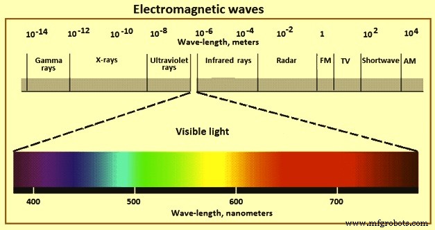
그림 1 전자기파
고대에는 거친 확대경이 사용되었지만 현대 현미경의 진화는 17세기에 시작되었습니다. 최초의 복합 현미경은 1595년 Hans와 Zacharias Janssen에 의해 제작되었지만 Antoni van Leeuwenhoek(1632–1723)는 매우 간단한 현미경으로 약 300배의 놀라운 배율을 달성할 수 있는 뛰어난 렌즈를 만들었습니다. 1670년경 과학자 Robert Hook의 제안으로 런던의 기기 제작자인 Christopher Cock은 매우 성공적인 복합 현미경을 만들었습니다. Hook은 이 장비로 세포를 관찰할 수 있었습니다. Hook의 현미경은 현대 악기의 아버지라고 할 수 있습니다.
흔히 '광현미경'이라고 하는 광학현미경은 가시광선(그림 1)과 렌즈 시스템을 사용하여 작은 샘플의 이미지를 확대하는 일종의 현미경입니다. 광학 현미경은 가장 오래되고 간단한 현미경입니다. 정교한 전자 금속학 기기의 발전에도 불구하고 미세 구조 연구에 매우 중요한 기기입니다. 정교한 '주사형 전자현미경'(SEM)과 '투과형 전자현미경'(TEM)도 귀중한 도구입니다. 그러나 광학현미경과 함께 사용하는 것이 아니라 대용으로 사용해야 합니다.
미세구조의 모든 검사는 광학현미경의 사용으로 시작하여 100배와 같은 낮은 배율에서 시작하여 미세구조의 기본 특성을 효율적으로 평가하기 위해 점차적으로 더 높은 배율로 진행합니다. 대부분의 미세구조는 광학현미경으로 관찰할 수 있으며 특성에 따라 식별할 수 있습니다. 의심스럽거나 알려지지 않은 성분의 식별은 매트릭스에 대한 경도, 자연 색상, 편광에 대한 반응 및 선택적 에칭제에 대한 반응을 관찰함으로써 도움을 받을 수 있습니다. 이러한 관찰은 검사되는 재료의 물리적 야금에 대한 알려진 세부 사항과 비교됩니다. 여전히 의심이 남아 있거나 구조가 너무 미세하여 관찰할 수 없다면 더 정교한 기술을 구현해야 합니다.
광학 현미경은 연마되거나 에칭된 금속 조직 샘플을 검사하는 데 사용할 수 있습니다. 특정 구성 요소는 에칭 세부 사항에 의해 가려지지 않기 때문에 연마된 상태로 더 쉽게 관찰됩니다. 포함물, 질화물, 특정 탄화물 및 금속간 상을 에칭 없이 쉽게 관찰할 수 있습니다. 개재물을 제외하고 최종 연마 중에 약간의 릴리프가 도입되면 다른 단계를 더 쉽게 검사할 수 있습니다. 시료는 인공물로 인한 합병증 없이 미세구조를 정확하게 관찰하고 해석할 수 있도록 적절하게 준비되어야 합니다. 입방이 아닌 결정 구조를 가진 재료와 같이 편광에 반응하는 샘플은 일반적으로 에칭 없이 검사됩니다. 그러나 대부분의 경우 미세 구조를 관찰하기 위해 에칭을 수행해야 합니다. 범용 에천트는 일반적으로 입자 구조와 존재하는 상을 밝히기 위해 먼저 사용되며, 그 다음에 관심 있는 특정 상을 공격하거나 착색하는 선택적 에천트가 사용됩니다. 선택적 에칭액은 특히 자동화 장치를 사용하여 수행하는 경우 정량적 금속학에 널리 사용됩니다. 두 경우 모두 미세 구조를 명확하게 나타내기 위해 에칭을 주의 깊게 수행해야 합니다.
현미경은 매우 확대된 이미지를 형성하기 위해 매우 짧은 초점 거리의 대물 렌즈를 사용합니다. 이 이미지는 간단한 돋보기로 사용되는 짧은 초점 거리의 접안렌즈로 볼 수 있습니다. 광학현미경의 기본적인 이미징 개념과 구조는 그림 2와 같다. 현미경의 광학계는 주로 대물렌즈와 접안렌즈로 구성된다. 대물렌즈의 목적은 물체를 확대하여 사용자가 명확하게 관찰할 수 있도록 하는 것입니다. 관찰하는 동안 물체 공간에서 대물렌즈의 초점면 근처에 샘플을 놓고 중간면에 샘플의 확대된 실상을 먼저 생성합니다. 중간 평면은 접안 렌즈의 초점 평면에 위치하므로 접안 렌즈는 중간 이미지 평면에 투영된 이미지를 더 확대하는 돋보기 역할을 합니다. 마지막으로 관찰자에게 확대된 가상의 반전 이미지가 제공됩니다.
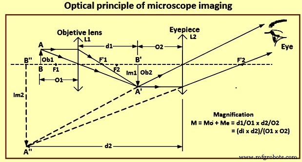
그림 2 현미경 이미징의 광학 원리
광학 현미경이 물체의 여러 지점에서 분리 가능한 이미지를 생성하는 능력은 제한적입니다. 렌즈의 해상력은 이 능력의 양적 척도입니다. 해상도 한계보다 가까운 점은 별도의 점으로 구분할 수 없습니다. 1873년 에른스트 아베(Ernst Abbe)는 'd =l/2n sin A' 방정식에 의해 분리된 두 인접 점 사이의 최소 거리 d 값을 처음으로 고정했습니다. 여기서 'l'은 빛의 파장 'A'입니다. 는 렌즈 각도 조리개의 1/2이고 'n'은 물체와 렌즈 사이 매질의 굴절률입니다.
현재, 대물렌즈로 해결할 수 있는 두 물체 점의 가장 작은 선형 분리는 방정식 'd =1.22(l/2NA)'에 의해 주어진 레일리 기준에 의해 고정됩니다. 여기서 'l'은 빛의 파장이고, 'NA'는 대물렌즈의 개구수입니다. Abbe 기준과 Rayleigh 기준은 NA =n sin A에 의해 이미징 매체와 관련된 개구수이므로 매우 유사합니다. sinA의 최대값은 1(A =90도)이므로 이론적 최대 개구수는 1입니다. 공기 중 대물렌즈(n =1)는 NA =1입니다. 높은 NA는 고해상도의 필수 요건이므로 immersion optics가 개발되었습니다. 샘플은 물(n =1.33), 글리세린(n =1.47) 또는 오일(n =1.52)과 같이 굴절률이 다른 침지 매체를 통해 대물렌즈에서 매우 짧은 거리에서 이미지화할 수 있습니다.
잘 설계된 현미경의 경우 공간 해상도는 주로 대물 렌즈에 의해 결정됩니다. 접안렌즈로도 이미지를 확대할 수 있지만 현미경의 해상력을 향상시킬 수는 없습니다. 광학 현미경의 공간 분해능은 Rayleigh 방정식 Ro =0으로 지정됩니다. 62 l/n sin A, 여기서 'Ro'는 분해 가능한 최소 거리, 'l'은 빛의 파장, 'n'은 렌즈와 물체 사이 매질의 굴절률, 'A'는 1 -렌즈 각도 조리개의 절반, n sinA는 대물렌즈의 개구수입니다.
위의 방정식을 기반으로 하고 (i) 390 nm(나노미터)와 760 nm 사이의 파장을 가진 가시광선의 사용, (ii) 70도에서 75도 사이의 반각으로 최대 도달 가능한 조리개와 같은 실용적인 제한 사항을 고려합니다. 도 및 (iii) 굴절률을 높이기 위해 물이나 기름에 담그는 방법을 사용해야 하는 경우 기존 광학 현미경의 해상도는 200nm를 초과할 수 없습니다.
광학 현미경과 현미경의 단순화된 광파 경로가 그림 3에 나와 있습니다. 현대 광학 현미경은 공간 분해능이 200 nm 한계인 물체를 1,500배까지 확대할 수 있습니다. 광학 현미경은 다양한 기준을 사용하여 여러 유형으로 나눌 수 있습니다. 예를 들어, 조명 방식에 따라 투과형과 반사형이 있습니다. 투과현미경에서 빛은 투명한 물체를 통과합니다. 반사현미경은 현미경 렌즈의 상부에 설치된 광원이 불투명한 물체를 비추고 반사된 빛을 렌즈에 모은다. 또한 현미경은 관찰 방법에 따라 명시야 현미경, 암시야 현미경, 위상차 현미경, 편광 현미경, 간섭 현미경, 형광 현미경 등으로 구분할 수 있습니다.
각 현미경은 투과 또는 반사 접근 방식을 사용할 수 있습니다. 명시야 현미경은 모든 현미경 중에서 가장 대중적이고 널리 사용됩니다. 이러한 유형의 현미경을 사용하면 작업 환경의 변화에 따라 일부 관찰 대상의 투과(또는 흡수) 비율과 반사 비율이 달라집니다. 이러한 물체의 진폭은 조명 강도의 변화에 따라 달라집니다. 무색 투명한 물체는 조명된 빛의 위상이 변할 때만 볼 수 있습니다. 명시야 현미경은 빛의 위상을 변경할 수 없기 때문에 이러한 유형의 현미경을 사용할 때 무색 투명한 샘플은 보이지 않습니다.
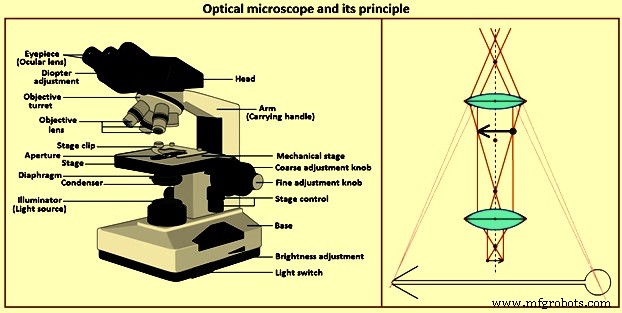
그림 3 광학현미경과 그 원리
현미경 구성요소
광학 현미경은 비용과 기능면에서 상당히 다양합니다. 반사광은 금속 연구에 사용됩니다. 투과광 현미경은 미네랄과 폴리머를 연구하는 데 사용되며 반사광을 사용하여 검사할 수도 있습니다. 광학 현미경은 또한 '직립형' 또는 '도립형'으로 분류됩니다. 이 용어는 관찰하는 동안 샘플의 연마면의 방향을 나타냅니다. 각 구성에는 장단점이 있으므로 개인 취향에 따라 선택합니다. 가장 단순한 광학 현미경은 벤치형(보통 수직)입니다. 일부 현미경에는 스탠드의 강성에 따라 사진 촬영 기능이 추가될 수 있습니다.
관찰 및 사진 현미경에 적합한 다양한 유형의 현미경을 사용할 수 있습니다. 이들은 다양한 조명 모드, 광원, 마이크로 경도 부착물, 핫 스테이지 등이 있는 다소 단순한 장치 또는 전체 규모 연구 현미경이 될 수 있습니다. 광학 현미경의 기본 구성 요소는 아래에 나와 있으며 그림 3에 나와 있습니다.
조명 시스템 – 광학현미경을 위한 다양한 광원을 사용할 수 있습니다. 주로 벤치현미경에 사용되는 저전압 텅스텐 필라멘트 램프는 관찰에 적합한 강도를 가지고 있지만 사진에는 적합하지 않습니다. 전구에 흐르는 전류를 변경하면 광도가 제어됩니다. 현미경에서 흔히 볼 수 있었던 탄소-아크 조명 시스템은 아크 또는 필라멘트 광원으로 대체되었습니다. 크세논 아크 광원은 높은 강도와 일광 색상 특성으로 인해 널리 사용됩니다. 그러나 광도는 중성 밀도 필터를 사용해야만 조정할 수 있습니다. 텅스텐-할로겐 필라멘트 램프는 또한 높은 강도와 높은 색온도 때문에 널리 사용됩니다. 빛의 강도는 전류를 변경하거나 중성 밀도 필터를 사용하여 제어할 수 있습니다. 지르코늄-아크, 나트륨-아크, 석영-요오드 또는 수은 램프와 같은 다른 광원은 덜 일반적입니다.
응축기 – 구면 수차와 코마가 없는 조정 가능한 렌즈를 광원 앞에 배치하여 광 경로의 원하는 지점에 빛을 집중시킵니다. 현미경 내부의 눈부심과 반사를 최소화하기 위해 필드 조리개가 이 렌즈 앞에 배치됩니다. 필드 다이어프램은 시야의 가장자리까지 정지됩니다. 두 번째 조정 가능한 조리개 조리개인 조리개 조리개는 수직 조명기 앞의 빛 경로에 배치됩니다.
이 조리개를 열거나 닫으면 빛의 양과 대물 렌즈에 들어오는 빛의 원뿔 각도가 변경됩니다. 이 조리개에 대한 최적의 설정은 각 대물 렌즈에 따라 다르며 이미지 대비, 선명도 및 피사계 심도 간의 절충안입니다. 배율이 증가하면 조리개 조리개가 조여집니다. 이 조리개를 열면 이미지 선명도가 증가하지만 대비가 감소합니다. 조리개를 닫으면 대비가 증가하지만 이미지 선명도가 저하됩니다. 조리개 조리개는 빛의 강도를 줄이는 데 사용되지 않습니다. 콘트라스트와 선명도에 대해서만 조정해야 합니다.
조명 필터 – 관찰의 용이성을 위해 빛을 수정하거나 사진 현미경을 개선하거나 대비를 변경하는 데 사용됩니다. 중성 밀도 필터는 가시 스펙트럼 전반에 걸쳐 균일하게 빛의 강도를 줄이는 데 사용됩니다. 약 85% ~ 0.01% 투과율의 다양한 중성 밀도 필터를 사용할 수 있습니다. 대부분의 광학 현미경에는 이러한 필터가 두 개 이상 선택되어 있습니다.
선택적 필터는 광원의 색온도와 필름의 색온도 균형을 맞추는 데 사용됩니다. 이것은 사용되는 광원과 필름 유형에 따라 컬러 이미지를 충실하게 재현하기 위해 자주 필요합니다. 녹색 또는 황록색 필터는 흑백 사진에서 렌즈 결함이 이미지 품질에 미치는 영향을 줄이기 위해 널리 사용됩니다. 대부분의 대물렌즈, 특히 비용이 저렴한 Achromat는 좋은 결과를 얻기 위해 이러한 필터링이 필요합니다.
편광 필터는 비입방(결정체) 재료의 검사를 위해 평면 편광(1개의 필터) 또는 교차 편광(소광을 생성하기 위해 회전된 두 개의 필터)을 생성하는 데 사용됩니다. 베릴륨, 지르코늄, 알파-티타늄, 우라늄과 같이 광학적으로 이방성인 물질은 에칭 없이 교차편광 상태에서 검사할 수 있습니다. 민감한 색조 플레이트는 교차 편광과 함께 사용하여 착색을 향상시킬 수도 있습니다.
대물 렌즈 – 미세구조의 1차 이미지를 형성하며 광학현미경의 가장 중요한 구성요소입니다. 대물 렌즈는 샘플에서 가능한 한 많은 빛을 수집하고 이 빛을 결합하여 이미지를 생성합니다. 대물렌즈의 NA는 렌즈의 집광 능력을 측정한 것입니다. 각도 'A'에 따라 집광 능력이 증가합니다. 조리개 조리개의 설정은 콘덴서의 NA를 변경하고 따라서 시스템의 NA를 변경합니다.
대물 렌즈(그림 4)는 일반적으로 4-6개의 대물렌즈를 수용할 수 있는 노즈 피스 포탑에 장착됩니다. 일부 현미경은 노즈 피스 터렛을 사용하지 않으며 한 번에 하나의 대물렌즈만 총검 마운트를 사용하여 수직 조명기에 배치할 수 있습니다. 수직 조명기에는 샘플 표면에 대물렌즈 아래로 빛을 편향시키는 반사기 또는 프리즘이 포함되어 있습니다. 일반적으로 조리개와 필드 다이어프램 및 필터도 고정합니다. 수직 조명기는 일반적으로 명시야 및 암시야 조명 또는 명시야 및 편광 조명과 같은 한 가지 또는 두 가지 유형의 조명만을 제공합니다. 그러나 이제 하나의 수직 조명기와 하나의 대물렌즈 세트로 모든 유형의 조명을 제공하는 범용 수직 조명기를 사용할 수 있습니다.
튜브 길이는 접안 렌즈의 아이 라인에서 대물 나사까지의 몸체 튜브의 길이입니다. 이 길이는 표준화되지 않았으며 다를 수 있습니다. 대부분의 대물렌즈는 일반적으로 160mm ~ 250mm의 특정 튜브 길이와 함께 사용하도록 설계되었으며 일반적으로 교환할 수 없습니다.
가장 일반적으로 사용되는 대물렌즈는 한 가지 색상(보통 황록색)에 대해 구형으로 보정되고 두 가지 색상(보통 빨강 및 녹색)에 대한 세로 색수차에 대해 구면으로 보정되는 achromat입니다. 따라서 무채색은 컬러 사진 현미경에 적합하지 않습니다. 황록색 필터와 ortho-chromatic 필름을 사용하면 최적의 결과를 얻을 수 있습니다. 그러나 achromat는 상대적으로 긴 working distance, 즉 대물렌즈의 전면 렌즈에서 샘플 표면까지의 거리를 제공합니다. 대물렌즈의 배율이 증가함에 따라 working distance가 감소합니다. 대부분의 생산자는 예를 들어 핫 스테이지 현미경과 같은 특수 용도를 위해 장거리 대물렌즈를 만듭니다. Achromat는 변형이 없어 편광 검사에 중요합니다. 고도로 수정된 다른 렌즈보다 적은 수의 렌즈를 포함하므로 내부 반사 손실이 최소화됩니다.
Semi-apochromatic 또는 형석 대물렌즈는 구면 및 색수차에 대해 더 높은 수준의 보정을 제공합니다. 따라서 무채색보다 더 높은 품질의 이미지를 생성합니다. Apochromatic 대물렌즈는 가장 높은 보정도를 가지며 최상의 결과를 생성하며 더 비쌉니다. Plano 대물렌즈는 시야의 평탄도를 광범위하게 수정하여 눈의 피로를 줄여주며 현대 현미경에서 흔히 볼 수 있습니다.
동초점 렌즈 시스템을 사용하면 노즈피스 포탑의 각 대물렌즈는 포탑이 회전할 때 거의 초점이 맞춰져 렌즈를 전환할 때 대물 전면 렌즈가 샘플을 때리는 것을 방지합니다. 많은 대물렌즈에도 스프링이 장착되어 있어 렌즈 손상을 방지할 수 있습니다. working distance가 매우 작을 수 있기 때문에 이것은 고배율 대물렌즈의 경우 더 큰 문제입니다.
특정 대물렌즈는 샘플과 대물렌즈 전면 렌즈 사이에 오일을 사용하도록 설계되었습니다. 그러나 오일 침지 렌즈는 사용 후 샘플과 렌즈를 세척해야 하므로 거의 사용되지 않습니다. 그러나 렌즈와 샘플 사이에 공기가 있을 때 얻을 수 있는 것보다 더 높은 해상도를 제공합니다. 후자의 경우 가능한 최대 NA는 0.95인 반면, 유침 렌즈는 1.3 NA ~ 1.45 NA, 사용하는 렌즈와 오일에 따라 25x에서 160x까지의 배율을 사용할 수 있습니다. 기름을 사용하면 이미지가 선명해지며, 이는 석탄이나 도자기와 같이 반사율이 낮은 표본을 검사할 때 유용합니다.
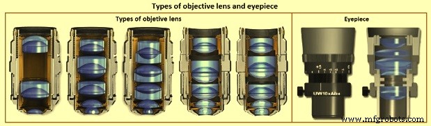
그림 4 대물렌즈와 접안렌즈의 종류
접안렌즈 – 접안렌즈라고도 합니다. 접안렌즈(그림 4)는 대물렌즈에 의해 생성된 기본 이미지를 확대합니다. 그러면 눈은 대물렌즈의 전체 해상도 기능을 사용할 수 있습니다. 현미경은 일반적으로 눈에서 250mm 떨어진 가장 뚜렷한 시각 지점에서 샘플의 가상 이미지를 생성합니다. 접안렌즈는 이 이미지를 확대하여 유용한 확대를 가능하게 합니다. 표준 접안렌즈는 직경이 24mm인 반면 평면 대물렌즈용 광시야 접안렌즈는 직경이 30mm이므로 기본 이미지의 사용 가능한 영역이 늘어납니다.
가장 단순한 접안렌즈는 C. Huygens가 디자인한 Huygenian 접안렌즈입니다. 대물 렌즈를 향한 볼록 표면이 있는 두 개의 평면 볼록 렌즈로 구성됩니다. 저배율 및 중배율 achromat 대물렌즈와 함께 사용하기에 적합합니다. 보정 접안렌즈는 높은 NA achromat 및 보다 고도로 수정된 대물렌즈와 함께 사용됩니다. 이러한 접안렌즈를 사용하여 일부 렌즈 보정이 수행되기 때문에 접안렌즈는 사용되는 대물렌즈 유형과 일치해야 합니다.
눈 클리어런스는 안구의 수정체와 눈 사이의 거리입니다. 대부분의 접안렌즈의 경우 눈 간격이 10mm 이하로 현미경을 사용하는 사람이 안경을 착용하면 충분하지 않습니다. 근시와 같은 단순한 시력 문제는 미세 초점 조정을 사용하여 해결할 수 있습니다. 난시와 같은 시력 문제는 현미경으로 교정할 수 없으며 안경을 착용해야 합니다. 하이아이 포인트 아이피스는 안경에 필요한 약 20mm의 아이클리어런스를 제공합니다.
접안 렌즈에는 일반적으로 미세 구조의 위치를 파악, 측정, 계산 또는 비교하기 위한 다양한 레티클 또는 계수선이 장착되어 있습니다. 접안렌즈는 십자선 또는 계수선 이미지와 기본 이미지를 확대합니다. 두 이미지에 동시에 초점이 맞춰져야 합니다. 계수선 눈금으로 만들 수 있는 것보다 더 정확한 측정을 허용하기 위해 특수 접안렌즈도 생산됩니다. 예를 들면 필라-마이크로미터 안구 또는 나사-마이크로미터 안구가 있습니다. 이러한 장치는 약 1마이크로미터까지 정확한 측정값의 직접 디지털 판독값을 생성하도록 자동화할 수 있습니다.
일반적으로 10배 배율 접안렌즈가 사용되지만 표준 배율을 얻기 위해 일부 시스템에서는 6.3배와 같은 다른 배율이 필요합니다. 1×, 15×, 20× 또는 25×와 같은 고배율 접안렌즈도 특정 상황에서 유용합니다. 전체 배율은 대물 배율 Mo에 접안 배율 Me를 곱하여 구합니다(그림 2). 줌 시스템이나 벨로우즈도 사용하는 경우 배율이 그에 따라 변경됩니다.
무대 – 샘플을 집속 및 이동시키기 위한 기계적 스테이지가 제공되며, 스테이지에 올려지고 클립으로 고정됩니다. 도립현미경의 스테이지에는 다양한 크기의 구멍이 있는 교체 가능한 중앙 스테이지 플레이트가 있습니다. 연마된 표면은 볼 수 있도록 구멍에 대고 배치됩니다. 그러나 전체 표면을 볼 수 없으며 고배율에서는 제한된 작동 거리로 인해 구멍 가장자리 근처에 대물렌즈의 초점을 맞출 수 없습니다. 직립현미경의 경우 샘플을 스테이지의 슬라이드에 올려놓습니다. 연마된 표면은 광선에 수직이어야 하므로 샘플 바닥과 슬라이드 사이에 점토를 놓습니다. 렌즈 티슈 조각을 연마된 표면 위에 놓고 샘플을 레벨링 프레스를 사용하여 점토로 누릅니다. 그러나 조직 조각이 샘플 표면에 부착될 수 있습니다. 장착된 샘플에 특히 유용한 대안은 조직 대신 링을 사용하여 샘플을 평평하게 하는 것입니다. 마운트와 동일한 크기의 알루미늄 또는 스테인리스 스틸 링 형태(바이스에서 약간 납작해진)가 샘플이 아닌 마운트에 안착됩니다.
수직 현미경을 사용하면 어떤 대물렌즈로도 전체 표면을 볼 수 있으며 작업자는 샘플의 어느 부분을 보고 있는지 확인할 수 있습니다. 코팅된 샘플, 용접 및 특정 영역을 검사해야 하는 기타 샘플의 특정 영역을 검사할 때 유용한 기능입니다. 마운트된 샘플의 경우 마운트용 자동 레벨링 스테이지 홀더를 사용하면 점토에서 샘플의 레벨링을 제거할 수 있습니다.
스테이지는 진동을 제거하기 위해 단단해야 합니다. x 및 y 마이크로미터로 제어되는 스테이지 이동은 부드럽고 정밀해야 하므로 일반적으로 랙 및 피니언 기어가 사용됩니다. 많은 단계에는 x 및 y 방향의 거리를 측정하기 위한 눈금이 있습니다. 포커싱 컨트롤에는 수직 움직임을 추정하기 위한 규칙이 포함되어 있는 경우가 많습니다. 일부 장치에는 전동식 단계와 초점 제어 장치가 있습니다.
원형 회전 가능한 스테이지 플레이트는 편광 검사를 용이하게 할 수 있습니다. 광물학 또는 암석학 연구에 일반적으로 사용되는 이러한 단계는 회전 각도를 측정할 수 있도록 눈금이 매겨져 있습니다. 직선형 스테이지는 일반적으로 원형 스테이지 위에 배치됩니다.
스탠드 – 벤치 현미경은 특히 광학 현미경이 장치에서 수행되는 경우 견고한 스탠드가 필요합니다. 현미경의 다양한 조각은 조립 시 스탠드에 부착됩니다. 어떤 경우에는 벤치 현미경이 사진 시스템을 고정하는 별도의 스탠드에 놓이기도 합니다.
렌즈 결함
많은 렌즈 결함은 반사 및 굴절 법칙으로 인해 발생합니다. 렌즈의 굴절률은 빛의 파장에 따라 달라지고 렌즈의 초점거리는 굴절률에 따라 달라집니다. 따라서 초점 거리는 빛의 색상에 따라 달라집니다. 존재하는 각 파장에 대한 별도의 이미지는 렌즈에서 서로 다른 거리에 초점을 맞춥니다. 이것은 세로 색수차입니다(그림 5). 또한 배율은 초점 거리에 따라 달라지므로 이미지 크기가 변경됩니다. 이것은 측면 색수차입니다(그림 5). 이러한 차이는 컬러 사진을 생성하기 위해 제거되어야 합니다. achromats는 이러한 문제에 대한 수정이 제한적이므로 선명한 이미지를 얻기 위해 황록색 빛 필터링과 함께 사용해야 합니다. 구면 수차(그림 5)는 광축에 있는 점 물체의 빛이 렌즈의 중심이나 주변에서 더 강하게 굴절되어 점 이미지가 유한 영역의 원으로 나타나는 일련의 초점 위치를 생성할 때 발생합니다. . 이것은 대물렌즈의 사용을 중앙 부분으로 제한하는 조리개를 사용하여 최소화할 수 있습니다. 렌즈 디자인도 이 문제의 일부를 수정할 수 있습니다.
최적 초점의 상면이 휘어지기 때문에 곡률은 같으나 반대인 보정 접안렌즈를 사용하여 평면 이미지를 생성합니다. 혼수 및 난시와 같은 기타 문제는 수정하지 않으면 이미지 품질이 저하될 수 있습니다.
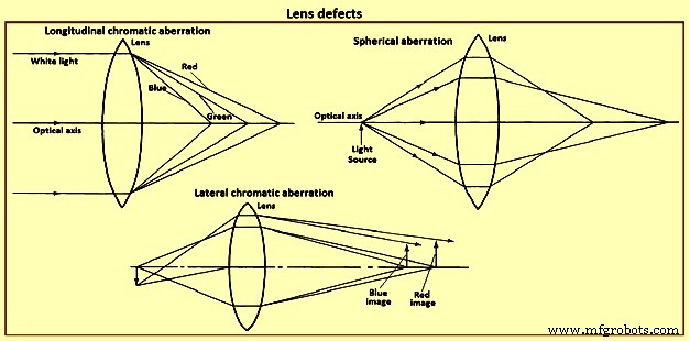
그림 5 렌즈 결함
해결책
미세 구조의 세부 사항을 보려면 적절한 해상도 또는 분해능과 적절한 이미지 대비를 생성하는 광학 시스템이 필요합니다. 해상도는 허용되지만 대비가 부족한 경우 세부 사항을 관찰할 수 없습니다. 일반적으로 거리 'd'만큼 떨어져 있는 두 점 또는 선을 분해하는 능력은 입사광의 파장 'l'과 개구수 NA, 의 함수입니다. 목표의. 이는 'd =k.l / NA' 방정식을 따릅니다. 여기서 k는 0.5 또는 0.61입니다. 그림 6은 k =0.61 및 4개의 광 파장에 대한 이러한 관계를 보여줍니다. 다른 공식도 보고되었습니다. 이 방정식은 대물렌즈의 보정 정도와 현미경을 통해 보는 사람의 시력과 같이 해상도에 영향을 미치는 다른 요소를 포함하지 않습니다. 자체 발광 점, 완벽한 흑백 대비, 투과광 검사, 이상적인 점광원, 렌즈 결함 부재와 같은 금속학에서는 볼 수 없는 조건에서 Abbe의 작업을 기반으로 합니다.
이전 단락의 방정식을 사용하여 NA가 1.4인 대물렌즈의 분해능 한계는 약 0.2마이크로미터입니다. 0.2마이크로미터 간격의 선이나 점을 보기 위해 필요한 배율은 대물렌즈의 해상력을 관찰 조건에서 결정하기 어려운 인간의 눈의 해상력으로 나누어 결정해야 합니다. Abbe는 최적의 시력을 위해 눈으로부터의 거리인 250mm의 거리에서 0.3mm의 값을 사용했습니다. 평균 파장이 0.55마이크로미터인 빛의 경우 필요한 배율은 대물렌즈 NA의 1,100배입니다. 이것이 최대 유용 배율에 대한 1,000NA 규칙의 기원입니다. 1,000NA를 초과하는 배율은 '빈', 즉 쓸모가 없다고 합니다.
1,000 NA 규칙에 대한 엄격한 준수는 금속학에서 직면하는 것과 확실히 다른 조건을 고려하여 그것이 개발된 조건을 고려할 때 의문을 제기해야 합니다. Abbe 분석에 따르면 최적의 20/20 시력과 최적의 대비 조건 및 평균 광파장 550nm의 광학 현미경을 사용하는 사람의 경우 대물렌즈의 NA를 최대한 활용하는 가장 낮은 배율은 NA의 550배입니다. <엠>. 이것은 주어진 대물렌즈와 함께 사용할 유용한 최소 배율을 설정합니다. 광학 현미경을 사용하는 일반 사람의 유용한 배율의 상한은 2,200NA, 라고 제안되었습니다. 1,000NA가 아닙니다.
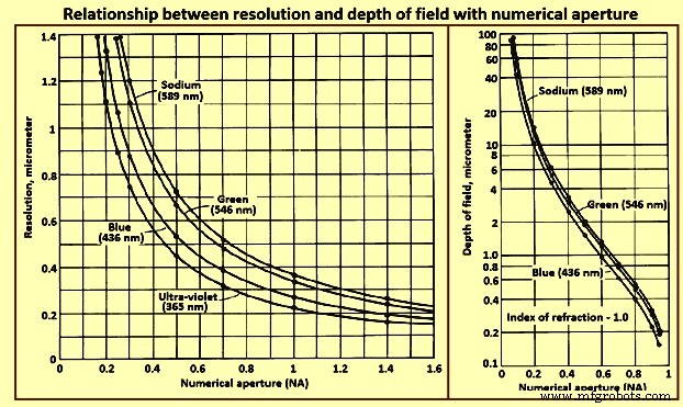
그림 6 개구수에서 해상도와 피사계 심도의 관계
피사계 심도
피사계 심도는 이미지 세부 사항이 허용 가능한 선명도로 관찰되는 광축을 따른 거리입니다. 해상도에 영향을 미치는 요소는 피사계 심도에도 영향을 주지만 반대 방향입니다. 따라서 배율이 증가함에 따라 더 어려워지는 이 두 매개변수 사이에 절충안이 도달해야 합니다. 이것이 고배율 검사에 라이트 에칭이 선호되는 이유 중 하나입니다.
시험 모드
선택한 대물렌즈의 분해능을 달성하려면 이미지 대비가 적절해야 합니다. 이미지 대비는 샘플 준비 및 광학 장치에 따라 다릅니다. 샘플 표면의 빛 반사율의 차이는 확대 후 눈에 보이는 진폭 특징을 생성합니다. 빛 반사에 의해 생성된 위상차는 현미경에 위상 대비 또는 간섭 대비 부착물을 사용하여 가시적으로 보여야 합니다.
명시야 조명 – 가장 널리 사용되는 관찰 방법인 명시야 수직 조명은 촬영한 현미경 사진의 대부분을 차지합니다. 작동 시 빛은 대물렌즈를 통과하여 샘플 표면에 수직으로 부딪힙니다. 입사광에 수직인 표면 형상은 대물렌즈를 통해 다시 접안렌즈로 빛을 반사하여 표면 형상이 밝게 나타납니다. 광선에 비스듬한 표면은 각도에 따라 대물렌즈에 더 적은 빛을 반사하고 더 어둡게 나타납니다.
비스듬한 조명 – 일부 현미경에서는 대물렌즈를 통과하는 빛이 샘플 표면에 수직이 아닌 각도로 부딪히도록 집광기 어셈블리 또는 미러를 분산시킬 수 있습니다. 샘플 표면의 거칠기는 그림자를 만들어 3차원 모양을 만듭니다. 이를 통해 릴리프 또는 리세스된 피쳐를 결정할 수 있습니다. 그러나 이 기술을 사용하면 조명이 균일하지 않게 되고 해상도가 떨어지기 때문에 약간의 비스듬함이 도입될 수 있습니다.
암시야 조명에서 – 암시야 조명에서 비스듬한 방향의 특징에서 반사된 빛은 수집되고 입사 광선에 수직인 특징에서 반사된 광선은 차단됩니다. 따라서 대비는 본질적으로 명시야 조명과 반대입니다. 즉, 명시야 조명에서 밝은 피처는 어둡게 나타나고 일반적으로 어두운 피처는 밝게 나타납니다. 이것은 비스듬한 특징이 밝게 나타나는 매우 강한 이미지 대비를 생성합니다. 이러한 조건에서는 명시야 조명을 사용하여 볼 수 없는 기능을 자주 볼 수 있습니다. 이 방법은 입자 구조를 연구하는 데 특히 유용합니다. 그러나 광도가 낮으면 현미경 검사가 더 어려워지며 자동 노출 제어 장치를 사용하면 문제가 줄어듭니다.
편광된 빛 – 금속학에서 사용되는 편광은 일반적으로 베릴륨, 알파-티타늄, 지르코늄 및 우라늄과 같은 특정 광학 이방성 금속의 관찰로 제한되어 왔습니다. Before development of the electron micro-probe analyzer (EMPA) and energy dispersive spectroscopy (EDS), polarized light examination was an integral part of the method for identifying inclusions. Since the development of these instruments, polarized light has been used less frequently for this purpose, since identification with the EMPA or EDS techniques is more definitive. Most metallurgical microscopes now use synthetic Polaroid filters. The ‘polarizer’ is placed in the light path before the objective, and the ‘analyzer’ is placed in the light path after the objective, normally just below the eyepiece.
Light consists of transverse waves vibrating in all directions at right angles to the direction of propagation. These vibrations occur symmetrically around the direction of propagation and are unpolarized. When light passes through a polarizing filter, the vibrations occur in only one plane in the direction of propagation, and the light is termed plane polarized. This plane changes as the filter is rotated. When the analyzer filter is placed in the light path, plane polarized light passes through it if the plane of vibration of the light is parallel to the plane of vibration of the analyzer. If the plane of vibration of the analyzer is perpendicular to that of the light the light does not pass through, and extinction results. When plane-polarized light is reflected from the surface of an isotropic metal (any metal with a cubic crystallographic structure, such as iron), then passes through the analyzer in the crossed position (plane of vibration perpendicular to that of the plane-polarized light), the image is extinguished, or dark. However, in practice, since the metallurgical microscope does not produce perfectly plane-polarized light, complete extinction does not occur. This is not a serious problem, since polarized light is used only in a qualitative manner in metallography. Strain-free objectives, normally achromats, are to be used. Fluorite or apochromatic objectives are unsuitable. A strong white-light source is needed to produce accurate colour effects.
If an optically anisotropic, polished metal is placed under the light beam with the polarizer and analyzer crossed, the microstructure is revealed. The quality of sample preparation is very important, and the surface is to be perpendicular to the light path. Rotation of the sample under the beam changes light intensity and colour. Since it is difficult to set the polarizer and analyzer in the crossed position accurately when an anisotropic sample is in place unless the crossed positions are marked on the polarizer and the analyzer, it is best to find this position first using an isotropic sample.
When plane-polarized light strikes an anisotropic metal surface, reflection occurs as two plane-polarized components at right angles to each other. The directions vary with crystal structure. The strength of these two perpendicular reflections can change, and a phase difference exists between them. These differences vary with each metal and depend on the crystal orientation. No reflection is obtained when the basal plane of hexagonal or tetragonal crystals is perpendicular to the light beam. Maximum reflectance occurs when the principal symmetry axis of the crystal is perpendicular to the light beam. The resultant image is predominantly influenced by these orientation effects with phase differences are of little significance.
When the analyzer is crossed with respect to the polarizer, rotation of plane-polarized light from the anisotropic surface allows the light to pass through the analyzer, producing an image in which each grain has a different light intensity and colour, depending on its crystal orientation relative to the light beam. As the stage is rotated, each grain changes four times in intensity from light to dark during a 360 degree rotation. If the phase difference is appreciable, the light is elliptically polarized, the difference in intensity in each grain with rotation is less, and extinction is not observed. Colour images are obtained when the reflected plane-polarized light varies with wavelength. When little colour is present, a sensitive tint plate inserted between the polarizer and the objective enhance colouration.
Isotropic metals can be examined using crossed-polarized light if the surface can be rendered optically active by etching, staining, or anodizing. Procedures have been developed for several metals, however, all etched surfaces do not respond to polarized light. Normally, the etch s to produce etch pits or facets in each grain to cause double reflection at these features. Grains with different crystal orientations produce differently oriented pits or facets, yielding different degrees of elliptical polarization and hence varying light intensity. Anodizing produces a thick oxide film on the sample surface and irregularities in the film lead to double reflection.
Although the polarization response of anodized samples has been attributed to optical anisotropy of the film, experimentation has shown that the effect is due to film surface irregularities. Tint etchants produce surface films which result in interference colours which can be enhanced using polarized light. In general, best results are achieved when the analyzer is shifted slightly from the crossed position. In addition to its use in examining inclusions, anisotropic metals (antimony, beryllium, bismuth, cadmium, cobalt, magnesium, scandium, tellurium, tin, titanium, uranium, zinc, and zirconium, for example), and etched / anodized/ tint-etched cubic metals, polarized light is useful for examination of coated or deformed metals. Phase identification can also be aided in some cases. The internal structure of graphite nodules in cast iron is vividly revealed using polarized light. Martensitic structures are frequently better revealed using polarized light, which illustrate lath martensite in a high-strength iron-base alloy.
Phase contrast illumination – It permits examination of subtle phase variations in microstructures with little or no amplitude contrast from differences in the optical path at the surface (reflected light) or from differences in the optical path through the sample (transmitted light). Differences of height as small as 0.005 micrometers can be detected. Application of phase-contrast illumination in metallography has been limited. The technique needs a separate set of objectives and a special vertical illuminator.
Interference-contrast illumination – Differential interference-contrast illumination produces images with emphasized topographic detail similar to those observed using oblique illumination. Detail which is invisible or faintly visible using bright-field illumination can be revealed vividly with interference-contrast illumination. Examples of the topographic detail which can be revealed using differential interference-contrast illumination are the relative hardness of the constituents or the nature of the etching process, that is, which areas or constituents are attacked by the etchant. In some cases, other aspects of the structure can be revealed which are invisible or faintly visible in bright-field illumination.
Interference techniques – Several interference techniques are used to measure height differences on samples. Interference fringes on a perfectly flat surface appear as straight, parallel lines of equal width and spacing. Height variations cause these fringes to appear curved or jagged, depending on the unit used. The interference microscope divides the light from a single point source into two or more waves which are superimposed after traveling different paths. This produces interference. Two-beam and multiple-beam instruments are the two basic types of interferometers used. The measurements are based on the wavelength of the light used. Two-beam interferometers can measure height differences as small as ‘l’/20; multiple-beam interferometers, as small as ‘l’/200.
The Linnik-type interferometer is a two-beam reflecting microscope which uses non-polarized light. A beam-splitting prism produces two light beams from a monochromatic light source. One beam travels through the test piece objective to the test piece surface and is reflected back through the objective to the eyepiece. The other beam travels through the reference objective, strikes an optically flat reference mirror, and returns to the beam splitter, then to the eyepiece. If the path difference between the two beams is not equal or not a multiple of ‘l’/2, interference occurs and contour lines are formed which indicate locations of equal elevation. The height difference between adjacent fringes is ‘l’/2.
The Tolansky multiple-beam interferometer produces interference between many light beams by placing a reference mirror which is partially transmitting and partially reflecting very near the sample surface but slightly out of parallel. The reference mirror has a known reflectivity selected to approximate that of the surface. Light passes through the reference mirror and strikes the sample surface, is reflected by the sample surface, and interferes with the rays reflected between the reference mirror and the sample. The fringes produced by the multiple-beam interferometer are sharper than those from the two-beam interferometer, which accounts for the greater accuracy. The distance between the fringes is also ’l’/2. Elevations produce displacements of the fringes from parallel alignment. The displacement is compared to the distance between the fringes to obtain height measurements.
Light-section microscopy – The light-section microscope, also used to measure surface topography, complements interference techniques. Roughness differences from 1 micrometer to 400 micrometers can be measured, which is useful in examining machined surfaces and for measurement of surface layers or films. In operation, a slit is placed near the field iris in the illumination system and is imaged by an objective as a light line on the surface to be measured. Oblique illumination is used with a dark background. The light band is observed using a second objective which is identical to the first. The objectives are 45 degrees to the sample surface and 90 degrees to each other. A reticle in the eyepiece is used for measurements, or they are made on photographs. Vertical resolution is not as good as with interferometers, but lateral resolution is better.
Auxiliary techniques
Several special devices can be used with the optical microscope to get additional information. These techniques are described below.
Micro-hardness testing – Micro-indentation hardness data can be obtained by adding indenter attachments to the microscope. Single-purpose units also are made by many manufacturers of hardness test equipment. Loads are normally made from 1 g (gram) to 1,000 g, although some manufacturers have units for low loads (0.05 g to 200 g). Knoop or Vickers indenters can be used.
Hot-stage microscopy – Hot-stage microscope cells are available from several manufacturers. Single-purpose units can also be used. Cold-cell attachments have also been produced, but have rather limited use in metallography. The hot-stage microscope has been used to study phase transformations on heating or cooling or at constant temperature. Examination of reactions in the hot-stage microscope cell needs use of long-working-distance objectives, since the sample is held within the cell. Moreover, since the cell window is quartz, the objectives is to be quartz-corrected, especially those with magnifications of 20× or more.
Techniques other than chemical etching are to be used to view phase changes. Grain boundaries are to be thermally etched if the sample is held at a constant temperature in the vacuum. Grain-boundary grooving is easily observed using bright field illumination. Phase transformations are visible by the relief produced at the surface. Hence, shear reactions, such as those produced by martensite or bainite formation, are most easily observed. Other phase transformations are more difficult or impossible to observe. Transformations can be photographed in situ, for which motion picture cameras are normally used.
Special stages – These are available in a variety of configurations. Auto leveling stages for mounted samples are a typical example. Universal tilting stages have also been made for rapid manipulation of rough, irregular samples. Special stages have also been designed for handling small objects. A number of stages have been made for performing in situ experiments. Basic studies of solidification have been performed by in situ observation of the freezing of low-melting-point organic materials, such as camphene, which solidify like metals. Observation of the recrystallization of low-melting-point metals and alloys has been similarly observed. Special stages have been used to observe the progress of electrolytic polishing and etching. Cells have also been used for in situ examination of corrosion processes. Stages have been designed to observe a variety of processes involving static or dynamic stress, and devices have also been designed to permit physical extraction of inclusions.
Hot-cell microscopy – Metallographic preparation of radioactive materials needs remote-control preparation using specially designed hot cells. Special microscopes have been designed for use with the hot cell.
Field microscopy – When the microstructure of a component or large object which cannot be cut and moved to the laboratory is to be examined, portable laboratory equipment, made by several manufacturers, can be used to polish a section in situ. A portable microscope can be sometimes used to examine and photograph the microstructure. If this cannot be done, replicas can be made and examined using an optical microscope or an electron microscope.
Comparison microscopes – The need occasionally arises to compare two microstructures. Normally, this is carried out by placing micrographs from each sample side-by-side, but it can also be performed using special microscopes. A bridge comparator is used to combine images from two bench microscopes for simultaneous viewing.
Television monitors – Projection microscopes can be used for group viewing, but it is more common to display the microstructure on a black-and-white or colour monitor. A number of high-resolution closed-circuit systems are available.
Clean-room microscopy – The study of small particles is influenced by dust contamination during viewing. Hence, such work is to be performed in a clean box, clean bench, or clean room which is specially made to provide a dust free environment.
Image analyzers – The increased use of quantitative metallography, particularly for characterization of inclusions, has promoted development of automated image analysis systems based on television principles. Phases or constituents of interest are detected primarily by differences in light reflectivity which produce gray-level differences on the monitor. Majority of the stereological measurements can be made using these systems. Considerable automation has been achieved using automated stages and powerful minicomputers. Although these devices can be quite expensive, they have stimulated interest in stereology and its application to structure-property correlations.
Features are detected on as-polished or etched samples, depending on the nature of the feature of interest. If etching is needed, selective techniques are normally used. Field and feature-specific measurements are utilized. Field measurements measure all the detected features simultaneously, as in volume fraction measurements. In feature-specific measurements, each separate particle is measured sequentially. This procedure is normally used for shape and size measurements.
Some structures do not lend themselves to accurate measurements using such systems. For example, quantification of fracture surface detail cannot be performed using an automatic image analyzer, since the device cannot separate fracture features by gray level. Many transmission electron micrograph structures also cannot be analyzed using these devices. For such structures, semi-automatic tracing devices can be used with the operator performing detection with a light pen or stylus. These lower-cost systems can be used for nearly any stereological measurement. Because of the greater time needed for detection, they are less suitable for measurement problems which need sampling of many fields.
Photo-microscopy
Prior to the development of photographic attachments, microstructures were to be sketched. Although the need for such documentation is no more there, sketching remains useful as a teaching method. Photo-microscopy is important in metallography, since the photo-micrograph can faithfully reproduce the detail observed for others to view. With the equipment presently available, high-quality micrographs are easily produced. However, this needs careful attention to sample preparation, etching, and use of the microscope. Reproduction of false microstructures is all too common and has caused inaccurate interpretations, rejection of good materials, and faulty conclusions in failure analyses.
Historically, darkroom photographic procedures have been most prevalent. Since the introduction of instant photographic processes such as Polaroid, however, many photo-micrographs have been made using these materials, taking advantage of their speed and efficiency. However, image reproduction is sacrificed, and the process is to be repeated for each extra copy. Use of an automatic exposure device is necessary with instant process film to minimize waste. Traditional darkroom photographic methods need more effort, but yield better micrographs. Considerable automation in wet darkroom processes is possible, but frequent use of photo-microscopy is needed to justify the cost of such equipment.
Obtaining good micrographs needs adequate image contrast and resolution, uniform focus over the entire field, uniform lighting, and adequate depth of field. The light source is to be properly aligned, and the system is to be free of vibration. The yellow-green filter is to be employed to correct lens defects. The optics is to be clean, and the field and aperture diaphragms are to be adjusted correctly. The microscope is focused in a variety of ways, depending on the model. Several film formats can be used, such as plates, sheet film of different size, or 35-mm roll film. The magnification at the film plane is to be known. This is a simple procedure if the only variables are the objective and eyepiece magnification, but is more difficult when using a zoom system or bellows. A stage micrometer can be utilized to determine the true magnification.
A range of black-and-white and colour films is available for darkroom or instant techniques. The manufacturers of these films document film characteristics. Black-and-white films are normally used due to their lower cost. They show better contrast control, are easier to process, and are normally quicker to use than colour films. Colour film has some important uses for which its cost is justified. In traditional black-and-white photography, a negative image is produced first and is used to produce a positive image of the microstructure on suitable paper. The micrograph lasts for many years without any apparent change. Selection of the negative film is based on the format available, colour sensitivity, contrast, resolving power, speed, graininess, and exposure and development latitudes.
Some black-and-white films are not sensitive to the entire visible spectrum. Orthochromatic films are sensitive to all colours except orange and red. Panchromatic films are sensitive to all colours, although they emphasize blue and de-emphasize yellow. A yellow filter can be used to reduce this colour bias.
Orthochromatic films can be developed under dark red light, but panchromatic films need total darkness. Orthochromatic films are very good for photo-microscopy, particularly when a yellow-green filter is inserted to correct lens defects.
Film speed is a critical variable only when illumination is low, as in polarized light, interference-contrast, or dark-field illumination. Orthochromatic film has a medium contrast which is adequate for most structures. Contrast can be enhanced with a high-contrast film. The resolving power of a film defines its ability to record fine details in the image. Hence, a high-resolving-power film is desirable. Graininess depends on the size of the silver grains in the emulsion, the developer used, and the development time and temperature. High-speed films are grainier than low-speed films, making them less suitable for enlarging. Contact printing is preferred. It needs a large film size, but saves enlargement time. It produces better images and eliminates re-determining the magnification of the print. A fine-grain film provides the best resolution.
When a negative is exposed, there is an allowable range of exposures which produces a useful, printable negative. Wide exposure latitude is quite valuable. Each film includes information on its characteristic relationship between exposure time and density. The exposure selected is to be on the linear portion of the density-time curve. A good, dense negative allows suppression of some of the fine image defects during printing. An underexposed negative greatly restricts printing and normally results in a poor print. Development of negatives is rather simple and involves use of a developing solution, a stop bath, a fixing solution, as well as washing and drying.
The correct exposure is most easily determined using a built-in exposure meter. If this is not available, a test exposure series can be made. This is accomplished by pulling out the film slide completely and exposing the entire film for a time judged to be considerably shorter than that needed. The slide is then inserted so that it covers around 10 mm to 20 mm of the film, and the exposure is repeated. This is repeated incrementally until the slide is fully inserted, covering the film. After development, the correct time can be assessed based on the density of the negative in each band.
Alternatively, the step exposure can be performed using an instant film of the same speed, saving the darkroom time. Majority of the black-and-white films are contact printed. The negative is placed emulsion side up on the contact printer, and a suitable paper is placed emulsion side down over the negative. The printer is closed, and light is passed through the film onto the paper. The print is developed, stopped, fixed, washed, and dried. Print contrast is controlled by the type of paper and development time. Print contrast types vary from extra-soft (flat) to extra-contrast (grades 1 to 5). Number 3 paper is used most frequently. Number 4 paper is used to increase contrast, and No. 2 paper to reduce contrast.
Instant process films eliminate the darkroom work, thus hastening the process. Polaroid prints use the diffusion-transfer reversal process. Development begins when the film is removed from the camera after the exposure. The action of pulling the film out of the camera crushes a pod containing the viscous, caustic developer and spreads it over the film. Black-and-white films develop rapidly while the colour prints need slightly more time. Some of the Polaroid films have very high speeds, an advantage in dim lighting. Some prints are to be coated with a neutralizing stabilizer / protective varnish to prevent staining and fading. Also available are instant films which produce a negative and a positive print. This negative is to be cleared, but a darkroom is not required. Polaroid films used in microscopy are all panchromatic. They are available as roll film, film packs, or sheets. Exposure times are to be more accurately controlled to get good prints than with traditional wet-process films.
Macro-photography
Examination and photography are frequently needed for such objects as macro-etched disks and broken parts. Examination can be performed visually or with the aid of a simple hand lens or stereo-microscope. Macro-photography can be performed using majority of the cameras, perhaps aided by the use of close-up lens attachments, a bellows, or a macro-lens. Many stereomicroscopes can be equipped with cameras for photography while some takes stereo-pairs. A few manufacturers offer camera stands for macro-photography. Some metallographs also have low-magnification objectives which can perform certain types of macro-photography.
Macro-photography utilizes magnifications from less than 1× to 50×. Most laboratories, especially those engaged in failure analyses, have various cameras, light sources, and stereo-viewers to cover the wide range of objects photographed. Correct lighting is necessary to emphasize details and provide even illumination without glare or reflection. Adjustment of lighting needs some experimentation and experience. Available lighting includes flood lamps, rings, coaxial, or fiber optics. A light box is useful for eliminating shadows, but considerable creativity is needed to achieve good results.
Depth of field and resolution are important variables. Many of the objects to be photographed are three-dimensional, which needs a certain depth of field and proper lighting to reveal shape and texture. Depth of field varies with the aperture diaphragm lens setting, the magnification, and the focal length of the lens. Stopping down the aperture improves depth of field, but decreases image brightness and clarity. Depth of field also increases as magnification decreases and focal length increases. For magnifications below 5×, focal lengths of 100 mm or more are preferred. Shorter-focal-length lenses are used for higher magnifications.
제조공정
광통신 산업은 지난 10년 동안 인상적인 성장을 보였습니다. 시장 규모는 2020년에만 187억 달러로 평가되었으며 2028년에는 376억 달러를 초과할 것으로 예상됩니다. 최근 몇 년 동안 이 산업의 인상적인 성장에 기여한 핵심 기술 중 하나는 CNC 가공입니다. 컴퓨터 수치 제어(CNC) 가공은 컴퓨터 코드에 의존하여 3D CAD 모델을 가공 부품으로 변환하여 광통신 부품 제작 시 매우 정확합니다. 이 기사에서는 CNC 가공 정밀 광학 부품의 기본 사항을 다룹니다. 또한 CNC 가공을 사용하여 제조할 수 있는 다양한 광통신
품질은 회사 성공의 열쇠이며 기계 산업은 제품 품질을 매우 중요하게 생각합니다. 따라서 제품별 검사도구가 특히 중요하므로 오늘은 기계가공업계의 검사도구인 현미경을 소개하고 주로 현미경의 작동방법과 유지관리에 대해 소개하도록 하겠습니다. 현미경이란 무엇입니까? 현미경 디자인은 컴팩트하고 크기가 작으며 무게가 가볍습니다. 그것은 작은 악기와 장비입니다. 그것은 두 부분으로 구성됩니다. 하나는 관찰 현미경이고 다른 하나는 표시를 쉽게 읽을 수 있는 정밀 이동식 크로스 테이블입니다. 처리 기회가 제한된 곳에서 사용할 수 있습니다. 현