

제조공정

산업 제조
비파괴 테스트 기법
결정 격자 결함으로 인해 재료에 고유한 미세한 결함이 있을 수 있습니다. 또한 용접, 주조, 단조, 표면처리 등의 제조공정에서 추가적인 흠집이나 불량이 발생할 수 있습니다. 또한, 재료는 응력, 피로 및 부식의 다양한 조건에서 사용되어 추가 결함을 생성하거나 기존 결함을 악화시킬 수 있습니다. 재료 파손은 일반적으로 이러한 불완전성이 위험한 비율에 도달하여 재료의 나머지 부분이 받는 응력을 견딜 수 없어 연성 또는 취성이 될 때 발생합니다. 따라서 재료에서 이러한 결함을 감지하고 특성, 크기 및 위치 측면에서 평가할 필요가 있습니다. 재료가 허용되는지, 수리 후 허용되는지 또는 거부되어 폐기되어야 하는지를 결정하기 위해 결함의 심각성을 평가하기 위한 추가 단계가 필요합니다.
비파괴 검사(NDT)는 부품 또는 시스템의 서비스 가능성을 손상시키지 않으면서 불연속성 또는 특성의 차이라고도 하는 결함에 대해 재료, 구성 요소 또는 어셈블리를 검사, 테스트 또는 평가하는 기술입니다. 즉, 검사나 테스트가 완료된 후에도 부품을 계속 사용할 수 있습니다. 이 기술은 개별 조사를 위해 샘플링 기반으로 적용하거나 생산 품질 관리 시스템에서 100% 재료 검사에 사용할 수 있습니다. 표면 질감, 제품 무결성 및 미래 유용성을 손상시키지 않고 재료 또는 구조를 검사 및/또는 측정하는 것이 가능합니다.
NDT는 첨단 기술 개념이지만 장비의 발전으로 인해 모든 제조 단계의 모든 산업 환경에 적용할 수 있을 만큼 충분히 견고해졌습니다. 그 적용 범위는 철강 생산에서 이미 사용 중인 구성 요소의 현장 검사에 이르기까지 다양합니다. 제품에 관한 최대한의 정보를 얻고 결과적으로 생산 시설에 피드백을 얻기 위해서는 NDT 기술을 적절하게 적용하는 데 어느 정도의 기술이 필요합니다. 비파괴검사는 불량품을 불합격시키는 방법일 뿐만 아니라, 좋은 재료가 좋다고 판단하는 보증이기도 합니다. 이 기술은 다양한 원리를 사용합니다. 모든 상황에서 모든 요구 사항을 충족하기 위해 블랙박스를 구축할 수 있는 단일 방법은 없습니다.
비파괴검사의 분야는 구조적 구성요소와 시스템이 신뢰할 수 있는 방식으로 기능을 수행할 수 있도록 검사에 중요한 역할을 하는 매우 광범위하고 학제간입니다. NDT 테스트의 신뢰성을 보장하고 사용된 장비의 결함, 방법 또는 검사자의 기술 및 지식의 잘못된 적용으로 인한 특정 오류를 방지하기 위해 특정 표준도 만들어졌습니다. 성공적인 NDT 테스트를 통해 재료 상태와 결함을 찾고 특성화할 수 있습니다. NDT 기술은 일반적으로 상당한 작업자 기술이 필요하며 결과가 주관적일 수 있으므로 테스트 결과를 정확하게 해석하는 것이 어려울 수 있습니다.
NDT 기술 이름은 종종 침투 매체의 유형 또는 테스트를 수행하는 데 사용되는 장비를 나타냅니다. NDT 기술은 기존 기술과 비전통 기술로 분류할 수 있습니다. 기존의 NDT 기술에는 (i) 육안 또는 광학 검사, (ii) 액체 침투 테스트, (iii) 자분 테스트, (iv) 와전류 테스트, (v) 방사선 검사 및 (vi) 초음파 테스트가 포함됩니다. 비전통적인 NDT 기술은 특수 응용 분야에만 사용되며 중성자 방사선 촬영, 음향 방출, 적외선 테스트, 마이크로파 기술, 누출 테스트, 홀로그래피, 유도파 테스트, 지상 투과 레이더 및 레이저 테스트 등이 포함됩니다.
대부분의 NDT 기술에 공통적인 필수 요소는 (i) 프로빙 매체, (ii) 불연속성을 감지할 수 있도록 사용되는 매체에 적합한 테스트 샘플, (iii) 분포를 측정할 수 있는 검출기 또는 매체 변경, (iv) 평가에 적합한 감지기로부터 수신한 정보를 기록 또는 표시하는 기술, (v) 결과를 평가하기 위해 감지기 피드백을 해석하도록 훈련된 작업자.
NDA 기술은 테스트 중에 표시를 제공합니다. NDT에 적용되는 '표시'라는 용어의 정의는 '진정한 중요성을 결정하기 위해 추가 평가가 필요한 NDT를 통해 공개된 응답의 응답 또는 증거'입니다. 특정 NDT 기술이 부품에 적용되면 응답이 있습니다. 이 응답은 표시입니다. '반응'이라는 용어는 (i) 액체 침투 테스트를 수행할 때 '블리드 아웃', (ii) 자성 입자 테스트를 수행할 때 입자 축적, (iii) 다음과 같은 경우 방사선 필름의 밀도 변화를 의미합니다. 방사선 검사, (iv) 초음파 검사를 수행할 때 신호, (v) 와전류 검사를 수행할 때 미터 편향, 신호 또는 디지털 변화. 응답이 관찰되면 테스트를 수행하는 작업자는 이를 해석한 다음 (i) 거짓, (ii) 관련이 없음 또는 (iii) 관련성 또는 진정한 불연속성과 같은 표시 그룹 중 하나로 분류해야 합니다.
NDT 기술 중 어느 것도 가능한 모든 문제에 대한 솔루션을 제공하지 않습니다. 즉, 선택적인 대안이 아니라 서로 보완적입니다. 기존 기술의 기본 원리, 일반적인 응용, 장점 및 한계는 아래에 설명되어 있습니다.
시각적 또는 광학적 검사
육안 및 광학 검사 기술(그림 1)은 구성 요소의 표면 상태를 검사하는 데 사용됩니다. 육안 테스트는 생각할 수 있는 거의 모든 표면 상태에 널리 사용됩니다. 본질적으로 시각적 및 광학적 테스트는 간단하고 간단할 수 있습니다. 가장 간단한 방법으로 깨끗한 구성 요소는 장비 없이 적절한 조명에서 작업자가 검사할 수 있으며, 그렇게 쉬울 수 있습니다. 종종 작업자는 검사를 돕기 위해 휴대용 돋보기 렌즈에서 유연한 광섬유 범위 또는 원격 비디오 시스템에 이르는 광학 장비를 사용해야 합니다.
숙련된 작업자는 최적의 조건에서 아주 작은 균열도 감지할 수 있습니다. 그러나 반복성이 문제입니다. 조건이 최적화되지 않은 경우 동일한 작업자가 반복 검사에서 동일한 구성요소의 동일한 균열을 놓칠 수 있습니다. 이것이 작업자가 가능한 한 자주 결함 상태를 찾을 수 있는 최상의 기회를 제공하기 위해 광학 보조 장치가 자주 사용되는 이유입니다. 적절한 조명이 있는 깨끗하고 편안한 환경에서 검사를 수행해야 합니다.
안전, 작업 위치 및 대기 조건에 주의를 기울여야 합니다. 검사에는 작업자의 상당한 집중이 필요합니다. 조명은 매우 중요하며 결과에 큰 영향을 줄 수 있습니다. 자연광은 육안 검사를 수행하는 데 가장 적합한 조명 유형입니다. 인공 조명은 육안 검사에도 사용할 수 있지만 작업자는 사용 중인 사양 또는 절차에 명시된 올바른 조명 수준을 확인해야 합니다.
구성 요소는 깨끗하고 보호 코팅이 없어야 합니다. 예를 들어 먼지나 페인트로 인해 원하는 표면 상태가 흐려질 수 있습니다. 작업자는 육안 검사를 수행하기 전에 충분한 교육과 경험을 갖는 것이 매우 중요합니다. 작업자는 시력도 좋아야 합니다. 알려진 바와 같이 눈은 놀랍도록 정교한 도구이지만 모든 것을 볼 수는 없습니다. 그것은 빛을 망막에 집중시키고 빛을 신경 자극으로 변환하여 뇌로 보내도록 설계되었습니다. 그런 다음 뇌는 이 정보를 처리하고 보이는 이미지를 형성합니다. 이것은 물리적 현실과 검사관이 보고 있다고 생각하는 관점의 차이인 인식으로 이어집니다. 검사관마다 눈에서 들어오는 정보를 다르게 해석하므로 동일한 물리적 장면을 모두 약간 다르게 봅니다.
Muller-Lyer 환상(그림 1)은 지각과 현실의 차이를 보여줍니다. 두 화살표의 축은 길이가 같지만 다른 것처럼 보입니다. 두 조사관 사이의 지각 차이는 훈련과 경험, 관찰 당시 관찰자의 정신적, 육체적 상태에 달려 있습니다. 지각은 피로와 건강의 영향을 받을 수 있습니다. 피로는 관찰자의 효율성과 시각적 능력을 감소시킵니다. 이러한 문제는 물리적 데이터의 부정확한 해석으로 이어집니다. 이상적인 검사는 훈련, 경험, 조명 및 환경 조건과 같은 모든 요소가 최적화된 검사입니다.
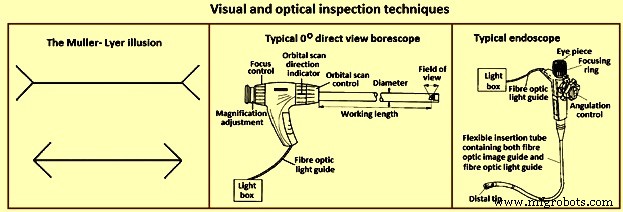
그림 1 육안 및 광학 검사 기술
일반적으로 육안 검사는 두 가지 유형의 보기 기술로 나뉩니다. 첫 번째 기술은 직접 보기입니다. 이러한 유형의 개체 보기에서 개체는 작업자의 즉각적인 존재에 있습니다. 이것은 도움 없이 또는 장비를 사용하여 수행할 수 있습니다. 두 번째는 원격 보기입니다. 여기서 물체의 보기는 오퍼레이터의 즉각적인 존재가 아니라 수행됩니다. 이것은 특수 장비를 사용하여 수행됩니다.
육안 검사는 거의 모든 것에 성공적으로 적용될 수 있습니다. 부식이나 균열과 같은 불연속성에서 페인트 칠한 표면의 얼룩 효과에 이르기까지 다양한 유형의 표면 상태를 찾는 데 사용할 수 있습니다. 숙련된 열처리 작업자는 칙칙한 체리 레드 스틸이 약 550℃에 있는 것과 같이 백열로 가열되면 시각적 외관에서 부품의 온도를 추정할 수도 있습니다.
연산자는 작은 불연속성을 찾는 데 자주 필요합니다. 이것은 육안으로 매우 어려울 수 있으므로 광학 보조 장치가 필요합니다. 가장 일반적인 광학 보조 장치 중 일부는 (i) 휴대용 돋보기 렌즈(일반적으로 1.5배 확대에서 최대 10배 확대), (ii) 각과 같은 표면 상태를 측정할 수 있도록 측정 눈금이 통합된 측정 돋보기입니다. 10배까지 확대되고 균일한 조명을 제공하기 위해 원형 형광관이 자주 내장되어 있는 돋보기, (iii) 다양한 유형과 다양한 배율 범위를 제공하는 현미경, (iv) 우수한 부품인 단단한 내시경 튜브 또는 파이프 내부를 검사하기 위한 장비(그림 1), (v) 도광판과 이미지 가이드 모두에 광섬유를 사용하기 때문에 내시경보다 더 유연한 내시경이라고 하는 유사한 장치(그림 1), ( vi) 이미지 품질을 개선하기 위해 내시경의 광학 시스템은 이미지 튜브를 포함할 수 있는 소형 비디오 카메라로 대체될 수 있습니다. 또는 전하 결합 장치 또는 전하 주입 장치와 같은 고체 촬상 장치를 포함할 수 있습니다.
액체 침투 테스트
액체 침투 시험(그림 2)의 기본 원리는 매우 낮은 점도(고유동) 액체(침투)가 부품 표면에 적용될 때 균열로 침투하고 표면에 열린 공극이 있다는 것입니다. 과잉 침투제가 제거되면 그 공극에 갇힌 침투제가 다시 흘러 나와 표시를 만듭니다. 침투 테스트는 자성 및 비자성 재료에 수행할 수 있지만 다공성 재료에는 잘 작동하지 않습니다.
감도를 낮추고 비용을 줄이기 위해 액체 침투 공정은 (i) 유화 후 형광 염료 침투, (ii) 용매 제거 가능한 형광 염료 침투, (iii) 물로 세척할 수 있는 형광 염료 침투, (iv) 유화 후 가시광선 침투제로 나열될 수 있습니다. 염료 침투제, (v) 용매 제거 가능한 가시성 염료 침투제, 및 (vi) 물로 세척할 수 있는 가시성 염료 침투제.
액체 침투 테스트의 장점은 (i) 상대적으로 저렴한 비용, (ii) 휴대성이 뛰어난 NDT 기술, (iii) 미세하고 단단한 불연속성에 대한 높은 민감도, (iv) 다양한 재료에 적용 가능, (v) 넓은 영역 검사입니다. . 액체 침투 기술의 한계는 (i) 테스트 표면에 모든 먼지, 오일, 그리스, 페인트 및 녹 등이 없어야 하고, (ii) 표면 불연속만 감지하고, (iii) 다공성 및 매우 심한 표면에는 사용할 수 없다는 것입니다. 거친 표면, (iv) 테스트 후 모든 침투성 물질의 제거가 자주 필요하며, (v) 영구적인 기록을 생성하는 쉬운 방법이 없습니다.
이 기술에서 침투제는 '가시적'일 수 있습니다. 즉, 주변광이나 형광등에서 볼 수 있으므로 '검은색' 조명을 사용해야 합니다. 가시적인 염료 침투제 공정은 그림 2에 나와 있습니다. 액체 침투제 테스트를 수행할 때 테스트 중인 표면이 깨끗하고 침투제가 표면에 열린 공극이나 균열로 들어가는 것을 차단할 수 있는 이물질이나 액체가 없어야 합니다. 부분. 침투제를 도포한 후 일정 시간(침투제 체류 시간) 동안 표면에 남아 있게 한 다음 부품을 조심스럽게 세척하여 표면에서 과도한 침투제를 제거합니다. 침투제를 제거할 때 작업자는 공극으로 유입된 침투제를 제거하지 않도록 주의해야 합니다. 그런 다음 현상제의 가벼운 코팅이 표면에 적용되고 보이드 또는 균열의 침투제가 현상제 안으로 스며들도록 허용하는 시간(현상제 체류 시간)이 제공되어 가시적인 표시를 만듭니다. 규정된 현상액 체류 시간 후에 부품을 육안으로 검사하거나 형광 침투제용 블랙 라이트를 사용하여 부품을 검사합니다. 대부분의 현상액은 사용 중인 침투제와 색상 대비를 제공하는 미세한 흰색 활석 같은 분말입니다.
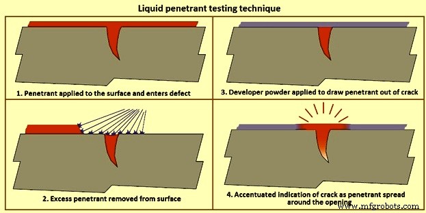
그림 2 액체 침투 테스트 기술
용매 제거 가능한 침투제는 과잉 침투제를 제거하기 위해 물 이외의 용매가 필요한 침투제입니다. 이 침투제는 일반적으로 자연에서 볼 수 있으며 일반적으로 흰색 현상액과 잘 대조되는 밝은 빨간색으로 염색됩니다. 일반적으로 침투제를 부품에 스프레이 또는 브러시로 도포한 다음 침투제 체류 시간이 경과한 후 침투제를 적신 천으로 부품을 세척한 후 현상액을 도포합니다. 현상액 체류 시간에 따라 현상액을 통해 보이는 침투성 블리드아웃을 감지하기 위해 부품을 검사합니다.
물 세척이 가능한 침투제는 침투제에 유화제가 포함되어 있어 물 스프레이를 사용하여 침투제를 제거할 수 있습니다. 침투제 탱크에 부품을 담그는 것이 가장 일반적이지만 침투제는 스프레이 또는 브러시로 큰 부품에 적용될 수 있습니다. 부품이 침투제로 완전히 덮이면 부품을 침투제 체류 시간 동안 배수판에 놓고 헹굼 스테이션으로 가져가 과잉 침투제를 제거하기 위해 코스 워터 스프레이로 세척합니다. 과도한 침투제가 제거되면 물이 제거될 때까지 부품을 따뜻한 공기 건조기 또는 부드러운 팬 앞에 놓을 수 있습니다. 그런 다음 부품을 건조한 현상액 탱크에 넣고 현상액으로 코팅하거나 남은 체류 시간 동안 그대로 둔 다음 검사할 수 있습니다.
유화 후 침투제는 물로 세척할 수 있는 침투제와 같이 화학 성분에 유화제가 포함되어 있지 않은 침투제입니다. 후유화성 침투제를 유사한 방식으로 도포하지만, 수세 단계 전에 유화제를 소정 시간(유화제 체류 시간) 동안 표면에 도포하여 과잉 침투제를 제거한다. 유화제 체류 시간이 경과하면 부품은 수세성 침투제와 동일한 수세 및 현상 공정을 거칩니다. 유화제는 친유성(유성) 또는 친수성(수성)일 수 있습니다.
자성 입자 테스트
자분 테스트는 하나 이상의 자기장을 사용하여 강자성 물질의 표면 및 표면 근처의 불연속성을 찾습니다. 강자성 재료의 표면 및 약간의 표면 아래 불연속성 또는 결함을 찾는 데 사용됩니다. 자화 부품에 존재하는 이러한 결함은 자기장, 즉 자속이 부품을 떠나게 합니다. 자성 입자가 이 표면에 적용되면 자속 누출에 의해 제자리에 고정되어 시각적 표시를 제공합니다. 자분 테스트의 여러 다른 방법을 사용할 수 있지만 모두 동일한 일반 원칙에 의존합니다. 따라서 모든 자분 시험은 부품에 자기장을 생성하고 시험 표면에 자분을 가하여 수행됩니다.
자기장은 영구자석이나 전자석으로 가할 수 있다. 전자석을 사용할 때 필드는 전류가 인가될 때만 존재합니다. 자기장이 자기장의 방향을 가로지르는 불연속성을 만나면 그림 3과 같이 자속선이 자체적으로 자속 누설 필드를 생성합니다. 이것은 매우 미세한 색상의 강자성 입자(자성 입자)가 ) 입자가 불연속 부분으로 당겨지는 부품의 표면에 적용되어 에어 갭을 줄이고 부품 표면에 가시적인 표시를 생성합니다. 자성 입자는 건조 분말이거나 액체 용액에 현탁될 수 있으며 가시성 염료 또는 자외선(검은색) 광선 아래에서 형광을 내는 형광성 염료로 착색될 수 있습니다.
교류(AC) 또는 직류(DC)를 사용하여 자기장을 유도할 수 있습니다. '표피 효과'로 인해 AC에 의해 생성되는 자기장은 테스트 대상의 표면에서 가장 강합니다. AC는 또한 부품 표면에 더 큰 입자 이동성을 제공하여 부품 표면이 불규칙할 수 있는 경우에도 플럭스 누출 영역을 찾기 위해 자유롭게 이동할 수 있습니다. DC는 더 큰 관통력을 갖고 표면 불연속 근처를 감지하는 데 사용할 수 있는 자기장을 유도합니다.
대부분의 현장 검사는 멍에를 사용하여 수행됩니다(그림 3). 전기 코일은 중앙 코어 주위에 감겨 있으며 전류가 인가되면 코어에서 관절 다리를 통해 부품으로 확장되는 자기장이 생성됩니다. 이것은 자속선이 한쪽 다리에서 다른 쪽 다리로 흐르기 때문에 세로 자화로 알려져 있습니다. 다리가 강자성 부품에 배치되고 요크에 전원이 공급되면 자기장이 부품에 도입됩니다. 플럭스 라인이 한 레그에서 다른 레그로 이어지기 때문에 레그 사이에 그려진 선에 수직인 방향의 불연속성을 찾을 수 있습니다. 표시가 누락되지 않도록 하기 위해 요크는 그림과 같은 위치에서 한 번 사용하고 표시가 누락되지 않도록 요크를 90도 돌려서 다시 사용합니다. 모든 전류가 요크에 포함되고 자기장만 부분을 관통하기 때문에 이러한 유형의 적용을 간접 유도라고도 합니다.
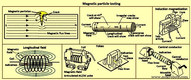
그림 3 자분 테스트
포크 장치는 전류가 부품을 통해 흐르고 원형 자기장이 그림 3과 같이 다리 주위에 생성되는 직접 유도를 사용합니다. 포크 사이의 자기장은 포크 사이에 그린 선에 수직으로 이동하기 때문에 표시는 평행하게 향합니다. 찌꺼기 사이에 그려진 선으로 찾을 수 있습니다. 멍에와 마찬가지로 두 번의 검사가 수행되고 두 번째 검사는 첫 번째 적용에 대해 90도 방향의 찌르기로 수행됩니다.
전기 코일은 세로 자기장을 생성하는 데 사용됩니다. 활성화되면 전류는 코일을 구성하는 와이어 주위에 자기장을 생성하여 결과적인 자속선이 코일을 통해 배향되도록 합니다. 세로 필드로 인해 코일에 배치된 부품의 표시는 세로 필드를 가로질러 배향됩니다.
대부분의 수평형 습식 목욕 기계(벤치 장치)에는 코일과 전류가 통과하여 자기장을 생성할 수 있는 헤드 세트가 모두 있습니다. 이 기계는 액체 용액에 형광 자성 입자를 사용하므로 '습식욕'이라는 이름이 붙었습니다. 헤드 사이의 부품을 테스트할 때 헤드 사이에 부품을 놓고 이동 가능한 헤드를 위로 이동하여 테스트 중인 부품을 헤드 사이에 단단히 고정하고 부품을 자성 입자 및 입자가 부품 위로 흐르는 동안 전류가 가해집니다. 전류 흐름은 헤드에서 헤드로 흐르고 자기장은 전류에 대해 90도 방향이기 때문에 헤드 사이의 선에 평행한 방향의 표시가 보입니다. 이러한 유형의 검사를 일반적으로 '헤드 샷'이라고 합니다.
파이프, 튜브 및 피팅과 같은 중공 부품을 테스트할 때 그림 3과 같이 부품이 막대(중심 도체)에 매달려 있는 상태에서 전도성 원형 막대를 헤드 사이에 배치할 수 있습니다. 그런 다음 부품을 수조 용액으로 적십니다. 전류가 인가되어 부품이 아닌 중심 도체를 통해 이동합니다. 그런 다음 부품의 ID 및 OD를 검사할 수 있습니다. 헤드 샷의 경우와 같이 자기장은 전류 흐름에 수직이고 테스트 조각을 감싸므로 이 기술을 사용하여 부품 길이를 축으로 따라 내려가는 표시를 찾을 수 있습니다.
자분 테스트의 장점은 (i) 경제적이고, (ii) 육안 테스트에 도움이 되고, (iii) 고정식 또는 휴대형 장비가 될 수 있으며, (iv) 즉각적으로 반복 가능한 결과를 제공하고, (v) 효과적인 검사 기술이며, ( vi) 조영제 또는 형광성 소모품. 자분 테스트의 한계는 (i) 검사되는 부품이 강자성이어야 하고, (ii) 고전류가 필요하며, (iii) 표면 및 약간의 표면 아래 결함만 감지할 수 있고, (iv) 부품이 다음과 같아야 한다는 것입니다. (v) 부품이 깨끗하고 상대적으로 매끄러워야 함, (vi) 장비가 부피가 크고 무거울 수 있음, (vi) 전원 공급 장치가 일반적으로 필요함, (vii) 코팅이 표시를 가릴 수 있음, (viii) 재료 또는 부품 투과성이 손상될 수 있음 결과에 영향을 미칩니다.
와전류 테스트
와전류는 전자기 유도라는 과정을 통해 생성됩니다. 구리선과 같은 도체에 AC를 인가하면 도체 내부와 주위에 자기장이 발생합니다. 이 자기장은 AC가 최대로 상승함에 따라 확장되고 전류가 0으로 감소함에 따라 붕괴됩니다. 다른 전기 도체가 이 변화하는 자기장에 근접하게 되면 이 두 번째 도체에 전류가 유도됩니다. 이러한 전류는 보이드, 균열, 입자 크기의 변화, 코일과 재료 사이의 물리적 거리와 같은 재료의 특성에 영향을 받습니다. 이러한 전류는 센서로 사용되는 두 번째 코일에 임피던스를 형성합니다. 실제로 검사할 부품의 표면에 프로브를 놓고 전자 장비는 동일한 프로브를 통해 공작물의 와전류를 모니터링합니다. 감지 회로는 송신 코일의 일부입니다.
와전류 기술의 주요 응용 프로그램은 표면 또는 표면 아래 결함을 감지하는 것입니다. 이 기술은 제품의 재료 전도도, 투과성 및 치수에 민감합니다. 와전류는 교류 자기장(일반적으로 10Hz ~ 10MHz)을 받는 모든 전기 전도성 물질에서 생성될 수 있습니다. 교류 자기장은 일반적으로 코일을 통해 교류를 통과시켜 생성됩니다. 코일은 다양한 모양을 가질 수 있으며 10회에서 500회 사이의 와이어를 감쌀 수 있습니다. 제품에서 생성된 와전류의 크기는 전도도, 투자율 및 설정 형상에 따라 다릅니다. 재료 또는 형상의 변화는 코일 임피던스의 변화로 여자 코일에 의해 감지될 수 있습니다.
가장 단순한 코일은 한쪽 끝에 권선이 여러 번 감겨 있고 테스트할 제품의 표면 가까이에 위치한 페라이트 막대로 구성됩니다. 예를 들어 제품 표면에 균열이 발생하면 와전류가 균열 주위로 더 멀리 이동하며 이는 임피던스 변화로 감지됩니다(그림 4). 코일은 또한 일반적으로 구동 쌍이라고 하는 쌍으로 사용할 수 있으며 이 배열은 코일을 차동으로 연결하여 사용할 수 있습니다. 이러한 방식으로 '리프트 오프'(표면에서 프로브의 거리) 신호가 향상될 수 있습니다. 코일은 하나의 코일 권선이 1차 권선이고 하나(또는 2개) 코일 권선이 2차 권선으로 사용되는 변압기 유형 구성에서도 사용할 수 있습니다. .
감지된 와전류 신호에는 일반적으로 비디지털 디스플레이인 CRT(음극선관) 유형 디스플레이에 표시될 수 있는 진폭 및 위상 정보가 포함됩니다. 신호는 실제, 즉 절대 신호로 표시되거나 적절한 전자 장치를 사용하여 신호 변경만 표시될 수 있습니다. 하나의 제품 매개변수만 변경하면 최상의 결과를 얻을 수 있습니다. 균열의 존재. 실제로 와전류 신호의 변화는 구성, 경도, 질감, 모양, 전도성, 투자율 및 기하학의 차이로 인해 발생합니다. 어떤 경우에는 균열의 영향이 다른 매개변수의 변경으로 인해 숨겨질 수 있고 불필요한 거부가 발생할 수 있습니다. 그러나 필요에 따라 균열, 전도도, 금속 손실 등의 감지를 향상시키기 위해 구성, 크기 및 테스트 빈도에 대해 코일을 선택할 수 있습니다.
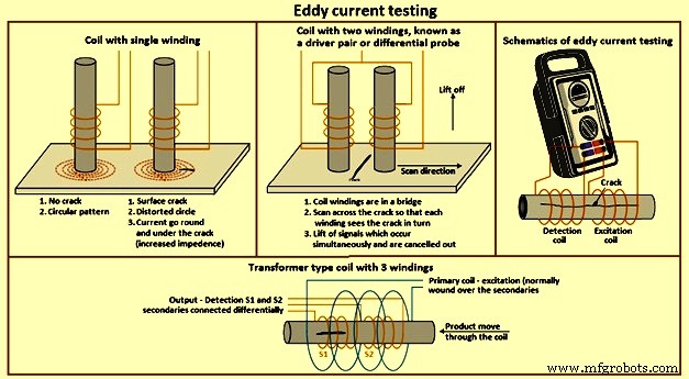
그림 4 와전류 테스트
와전류가 재료를 관통하는 깊이는 테스트 주파수를 조정하여 변경할 수 있습니다. 즉, 주파수가 높을수록 침투가 낮습니다. 그러나 주파수가 낮을수록 작은 결함에 대한 민감도가 낮아집니다. 더 큰 코일은 표면 거칠기에 덜 민감하며 그 반대의 경우도 마찬가지입니다. 최신 전자 장치는 절대 또는 차동 모드와 광범위한 주파수에서 광범위한 코일 구성을 작동할 수 있습니다. 단일 또는 복합 형상 부품의 균열에 대한 표면 테스트의 경우 단일 페라이트 코어드 권선이 있는 코일이 일반적으로 사용됩니다. 프로브는 구성 요소에 배치되고 전자 장치 컨트롤을 사용하여 '밸런싱'됩니다. 프로브가 구성요소의 표면을 가로질러 스캔됨에 따라 균열이 감지될 수 있습니다.
표면이 자동으로 스캔되는 경우 단일 코일 권선은 리프트 오프 거리가 정확하게 유지되는 경우에만 적합합니다. 일반적으로 차동 코일 구성은 리프트 오프 효과, 진동 효과 등이 허용 가능한 정도로 상쇄될 수 있는 고속 스캐닝 시스템에 사용됩니다. 튜브, 막대 및 와이어는 둘러싸는 코일을 사용하여 검사할 수 있으며 일반적으로 1차 코일 1개와 2차 코일 2개가 차동으로 연결된 코일 구성을 가지고 있습니다.
대부분의 와전류 전자 장치에는 위상 디스플레이가 있으며 이를 통해 작업자는 결함 조건을 식별할 수 있습니다. 많은 경우 균열, 리프트 오프 및 기타 매개변수의 신호를 명확하게 식별할 수 있습니다. 두 개 이상의 서로 다른 테스트 빈도에서 동시에 제품을 검사할 수 있는 장치도 있습니다. 이러한 장치를 사용하면 결함 감지를 개선하기 위해 원하지 않는 특정 효과를 전자적으로 취소할 수 있습니다.
와전류 테스트는 순전히 전기적입니다. 코일 유닛은 제품 표면에 접촉할 필요가 없으므로 기술을 쉽게 자동화할 수 있습니다. 대부분의 자동화 시스템은 기계적 처리가 단순화된 단순한 형상의 구성 요소를 위한 것입니다.
와전류 테스트의 장점은 (i) 다양한 엔지니어링 금속에서 결함 감지, 구성, 경도, 전도도, 투자율 등과 같은 전도성 물질의 광범위한 조건을 결정하는 데 적합합니다. 위상 디스플레이 전자 장치를 사용하여 훨씬 더 많은 제품 정보를 얻을 수 있으므로 간단한 용어로 자주 제공될 수 있습니다. 수리), (v) 다양한 애플리케이션에 적합한 프로브 및 테스트 주파수 선택의 유연성, (vi) 전체 자동화에 적합 와전류 테스트의 단점은 (i) 와전류 응답에 영향을 미치는 광범위한 매개변수가 원하는 재료 특성(예:크랙은 원하지 않는 매개변수로 마스킹될 수 있습니다. 경도 변화, 따라서 일부 응용 분야에서는 프로브 및 전자 장치의 신중한 선택이 필요하며 (ii) 일반적으로 테스트가 제한됩니다.
방사선 검사
방사선 검사 방법은 다양한 재료 및 구성에서 내부 결함을 감지하는 데 사용됩니다. 전기적으로 생성된 X선과 방사성 동위 원소에서 방출되는 감마선은 투과 방사선이며 통과하는 물질에 차등적으로 흡수됩니다. 두께가 두꺼울수록 흡수율이 높아집니다. 또한 밀도가 높을수록 흡수율이 높아집니다. X선과 감마선은 빛과 마찬가지로 필름에 도달하는 방사선의 세기에 비례하여 사진 필름의 할로겐화은 결정을 부분적으로 금속 은으로 변환시켜 잠상을 형성하는 성질을 가지고 있습니다. 이는 일반 사진 필름과 유사한 방식으로 현상 및 고정할 수 있습니다(그림 5).
내부 보이드가 있는 재료는 방사선 소스와 필름 사이에 피사체를 배치하여 테스트합니다. 공극은 깨끗한 배경에서 더 많은 방사선이 필름에 도달한 어두운 영역으로 표시됩니다. 원칙은 X선과 감마선 방사선 촬영 모두 동일합니다.
X선 방사선 촬영에서 투과력은 X선관에 가해지는 볼트 수에 의해 결정됩니다. 강철의 경우 두께는 인치당 약 1,000볼트입니다. 감마선 방사선 사진에서 동위원소는 투과력을 지배하며 각 동위원소에서 변경할 수 없습니다. 따라서 이리듐 192는 15mm ~ 25mm 두께의 강철에 사용되며 세슘 134는 20mm ~ 265mm 두께의 강철에 사용됩니다. X선 방사선 사진에서 강도, 즉 노출 시간은 튜브에 있는 음극의 암페어 수에 의해 결정됩니다. 노출 시간은 일반적으로 밀리암페어 분 단위로 표시됩니다. 감마선을 사용하면 동위 원소를 공급할 때 방사선의 강도가 설정됩니다. 동위 원소의 복사 강도는 베크렐 단위로 측정되며 시간이 지남에 따라 감소합니다. 퀴리 양이 반으로 감소하는 데 걸리는 시간이 반감기이며 각 동위원소의 특징입니다. 예를 들어, 이리듐 192의 반감기는 74일이고 세슘 134는 2.1년입니다.
노출 계수는 일반적으로 퀴리 시간으로 표시되는 퀴리 수와 시간의 곱입니다. The time of exposure is to be increased as the isotope decays. When the exposure period becomes uneconomical the isotope is to be renewed. As the isotope is continuously emitting radiation it is to be housed in a container of depleted uranium or similar dense shielding material, whilst not exposed for protecting the environment and personnel.
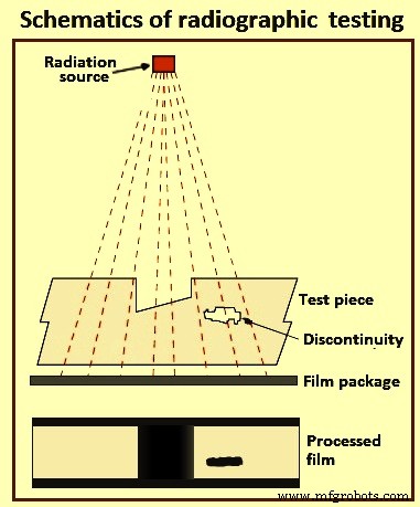
Fig 5 Schematics of radiographic testing
To produce an x-ray or gamma ray radiograph, the film package ((enclosed in a light tight cassette and comprising film and intensifying screens, the latter being required to reduce the exposure time) is placed close to the surface of the subject. The source of radiation is positioned on the other side of the subject some distance away, so that the radiation passes through the subject and on to the film. After the exposure period the film is removed, processed, dried, and then viewed by transmitted light on a special viewer. Different radiographic and photographic accessories are necessary, including such items as radiation monitors, film markers, image quality indicators, dark-room equipment, etc. As far as the last is concerned there are many degrees of sophistication, including fully automatic processing units. These accessories are the same for both x-ray and gamma radiography systems. Also needed are such consumable items as radiographic film and processing chemicals
Recent developments in radiography permit ‘real time’ diagnosis. Such techniques as computerized tomography yield much important information, though these methods can be suitable for only investigative purposes and not generally employed in production quality control.
Industrial radiography involves exposing a test object to penetrating radiation so that the radiation passes through the object being inspected and a recording medium placed against the opposite side of that object. For thinner or less dense materials such as aluminum, electrically generated x-radiations (x-rays) are normally used, and for thicker or denser materials, gamma radiation is generally used. Gamma radiation is given off by decaying radioactive materials, with the two most commonly used sources of gamma radiation being Iridium-192 (Ir-192) and Cobalt-60 (Co-60). Ir-192 is normally used for steel upto 15 mm to 25 mm, depending on the Curie strength of the source, and Co-60 is normally used for thicker materials due to its greater penetrating ability. The recording media can be industrial x-ray film or one of several types of digital radiation detectors. With both, the radiation passing through the test object exposes the media, causing an end effect of having darker areas where more radiation has passed through the part and lighter areas where less radiation has penetrated. If there is a void or defect in the part, more radiation passes through, causing a darker image on the film or detector.
Film radiography uses a film made up of a thin transparent plastic coated with a fine layer of silver bromide on one or both sides of the plastic. When exposed to radiation these crystals undergo a reaction which allows them, when developed, to convert to black metallic silver. This silver is then ‘fixed’ to the plastic during the developing process, and when dried, becomes a finished radiographic film. To be a usable film, the area of interest on the film is to be within a certain density (darkness) range and is to show enough contrast and sensitivity so that discontinuities of interest can be seen. These items are a function of the strength of the radiation, the distance of the source from the film and the thickness of the part being inspected. If any of these parameters are not met, another exposure (is to be made for that area of the part.
Computed radiography is a transitional technology between film and direct digital radiography. This technique uses a reusable, flexible, photo-stimulated phosphor plate which is loaded into a cassette and is exposed in a manner similar to traditional film radiography. The cassette is then placed in a laser reader where it is scanned and translated into a digital image, which take from one to five minutes. The image can then be uploaded to a computer or other electronic media for interpretation and storage. Computed tomography uses a computer to reconstruct an image of a cross sectional plane of an object as opposed to a conventional radiograph. The computed tomography image is developed from multiple views taken at different viewing angles which are reconstructed using a computer. With traditional radiography, the position of internal discontinuities cannot be accurately determined without making exposures from several angles to locate the item by triangulation. With computed tomography, the computer triangulates using every point in the plane as viewed from many different directions.
Digital radiography digitizes the radiation which passes through an object directly into an image which can be displayed on a computer monitor. The three principle technologies used in direct digital imaging are amorphous silicon, charge coupled devices, and complementary metal oxide semi-conductors. These images are available for viewing and analysis in seconds compared to the time needed to scan in computed radiography images. The increased processing speed is a result of the unique construction of the pixels; an arrangement which also allows a superior resolution than is found in computed radiography and most film applications.
The advantages of radiographic testing include (i) is useful on wide variety of materials, (ii) can be used for checking internal mal-structure, misassembly or misalignment, (iii) provides permanent record, and (iv) devices for checking the quality of radiograph are available. Some of the limitations of this method are (i) access to both sides of the object is needed, (ii) cannot detect planar defects readily, (iii) thickness range which can be inspected is limited, (iv) sensitivity of inspection decreases with thickness of the test object, (v) considerable skill is needed for interpretation of the radiographs, (vi) depth of defect is not indicated readily, and (vii) x-rays and gamma rays are hazardous to human health.
Ultrasonic testing
Ultrasonic technique is used for the detection of internal and surface (particularly distant surface) defects in sound conducting materials. The principle is in some respects similar to echo sounding. A short pulse of ultrasound is generated by means of an electric charge applied to a piezo electric crystal, which vibrates for a very short period at a frequency related to the thickness of the crystal. In flaw detection, this frequency is normally in the range of one million to six million times per second (1 MHz to 6 MHz). Vibrations or sound waves at this frequency have the ability to travel a considerable distance in homogeneous elastic material, such as many metals with little reduction. The velocity at which these waves propagate is related to the Young’s Modulus for the material and is characteristic of the material. For example the velocity in steel is 5,900 metres per second, and in water 1,400 metres per second.
Ultrasonic energy is considerably reduced in air, and a beam propagated through a solid, on reaching an interface (e.g. a defect, or intended hole, or the back wall) between that material and air reflects a considerable amount of energy in the direction equal to the angle of incidence. For contact testing the oscillating crystal is incorporated in a hand held probe, which is applied to the surface of the material to be tested. To facilitate the transfer of energy across the small air gap between the crystal and the test piece, a layer of liquid (referred to as ‘couplant’), usually oil, water or grease, is applied to the surface. The crystal does not oscillate continuously but in short pulses, between each of which it is quiescent.
Piezo electric materials not only convert electrical pulses to mechanical oscillations, but also transduce mechanical oscillations into electrical pulses. Hence, there is not only a generator of sound waves but also a detector of returned pulses. The crystal is in a state to detect returned pulses when it is quiescent. The pulse takes a finite time to travel through the material to the interface and to be reflected back to the probe.
The standard method of presenting information in ultrasonic testing is by means of a cathode ray tube, in which horizontal movement of the spot from left to right represents time elapsed. The principle is not greatly different in digitized instruments that have a LCD (liquid crystal display) flat screen. The rate at which the spot moves is such that it gives the appearance of a horizontal line on the screen. The system is synchronized electronically so that at the instant the probe receives its electrical pulse the spot begins to traverse the screen. An upward deflection (peak) of the line on the screen is an indication of this occurrence. This peak is normally termed the initial pulse.
Whilst the base line is perfectly level the crystal is quiescent. Any peaks to the right of the initial pulse indicate that the crystal has received an incoming pulse reflected from one or more interfaces in the material. Since the spot moves at a very even speed across the tube face, and the pulse of ultrasonic waves moves at a very even velocity through the material, it is possible to calibrate the horizontal line on the screen in terms of absolute measurement. The use of a calibration block, which produces a reflection from the back wall a known distance away from the crystal together with variable controls on the flaw detector, allows the screen to be calibrated in units of distance, and hence determination of origins of returned pulses obtained from a test piece.
It is hence possible not only to discover a defect between the surface and the back wall, but also to measure its distance below the surface. It is important that the equipment is properly calibrated and, since it is in itself not able to discriminate between intended boundaries of the object under test and unintended discontinuities, the operator is required to identify the origin of each peak. Further as the pulses form a beam it is also possible to determine the plan position of a flaw. The height of the peak (echo) is roughly proportional to the area of the reflector, though there is on all instruments a control, which can reduce or increase the size of an indication – variable sensitivity in fact. Not only is part of the beam reflected at a material / air interface but also at any junction where there is a velocity change, for example steel / slag interface in a weld.
Probing all faces of a test piece not only discovers the three-dimensional defect and measures its depth, but can also determine its size. Two-dimensional (planar) defects can also be found but, unlike radiography, it is best that the incident beam impinges on the defect as near to right angles to the plane as possible. To achieve this some probes introduce the beam at an angle to the surface. In this manner longitudinal defects in tubes (inner or outer surface) are detected.
Interpretation of the indications on the screen requires a certain amount of skill, particularly when testing with hand held probes. The technique is, however, admirably suited to automatic testing of regular shapes by means of a monitor – an electronic device which fits into the main equipment to provide an electrical signal when an echo occurs in a particular position on the trace. The trigger level of this signal is variable and it can be made to operate a variety of mechanical gates and flaw warnings. Furthermore, improvements in computer technology allow test data and results to be displayed and out-putted in a wide variety of formats.
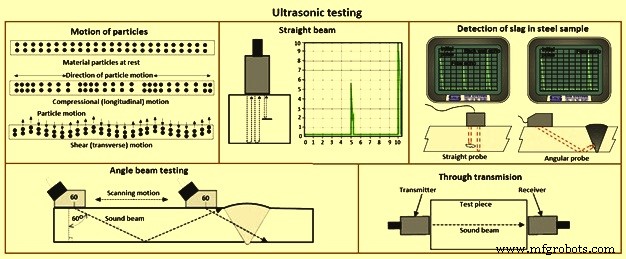
Fig 6 Ultrasonic testing
Modern ultrasonic flaw detectors are fully solid state and can be battery powered, and are robustly built to withstand site conditions. Since the velocity of sound in any material is characteristic of that material, it follows that some materials can be identified by the determination of the velocity. This can be applied, for example in spheroidal graphite cast irons to determine the percentage of graphite nodularity.
When the velocity is constant, as it is in a wide range of steels, the time taken for the pulse to travel through the material is proportional to its thickness. Hence, with a properly calibrated instrument, it is possible to measure thickness from one side with accuracy in hundredths of a millimeter. This technique is now in very common use. A development of the standard flaw detector is the digital wall thickness gauge. This operates on similar principles but gives an indication, in LED (light emitting diode) or LCD 9liquid crystal display) numerics, of thickness in absolute terms of millimetres. These equipments are easy to use but need prudence in their application.
The two most commonly used types of sound waves used in industrial inspections are the compression (longitudinal) wave and the shear (transverse) wave (Fig 6). Compression waves cause the atoms in a part to vibrate back and forth parallel to the sound direction and shear waves cause the atoms to vibrate perpendicularly (from side to side) to the direction of the sound. Shear waves travel at around half the speed of longitudinal waves. Sound is introduced into the part using an ultrasonic transducer (probe) which converts electrical impulses from the ultrasonic testing machine into sound waves, then converts returning sound back into electric impulses which can be displayed as a visual representation on a digital or LCD screen. If the machine is properly calibrated, the operator can determine the distance from the transducer to the reflector, and in many cases, an experienced operator can determine the type of discontinuity which caused the reflector. Because ultrasound does not travel through air (the atoms in air molecules are too far apart to transmit ultrasound), a liquid or gel called ‘couplant’ is used between the face of the transducer and the surface of the part to allow the sound to be transmitted into the part.
Straight beam inspection uses longitudinal waves to interrogate the test piece as shown at the right. If the sound hits an internal reflector, the sound from that reflector reflects to the transducer faster than the sound coming back from the back-wall of the part due to the shorter distance from the transducer. This results in a screen display. Digital thickness testers use the same process, but the output is shown as a digital numeric readout rather than a screen presentation.
Angle beam inspection uses the same type of transducer but it is mounted on an angled wedge (also called a probe) that is designed to transmit the sound beam into the part at a known angle. The most commonly used inspection angles are 45 degrees, 60 degrees, and 70 degrees, with the angle being calculated up from a line drawn through the thickness of the part (not the part surface). A 60 degree probe is shown in Fig 6. If the frequency and wedge angle is not specified by the governing code or specification, it is upto the operator to select a combination which adequately inspects the part being tested. In angle beam inspections, the transducer and wedge combination (also referred to as a probe) is moved back and forth towards the weld so that the sound beam passes through the full volume of the weld. As with straight beam inspections, reflectors aligned more or less perpendicular to the sound beam sends sound back to the transducer and are displayed on the screen.
Immersion Testing is a technique where the part is immersed in a tank of water with the water being used as the coupling medium to allow the sound beam to travel between the transducer and the part. The ultrasonic testing machine is mounted on a movable platform (a bridge) on the side of the tank so it can travel down the length of the tank. The transducer is swivel-mounted on at the bottom of a waterproof tube which can be raised, lowered and moved across the tank. The bridge and tube movement permits the transducer to be moved on the X-, Y- and Z-axes. All directions of travel are gear driven so the transducer can be moved in accurate increments in all directions, and the swivel allows the transducer to be oriented so the sound beam enters the part at the required angle. Round test parts are frequently mounted on powered rollers so that the part can be rotated as the transducer travels down its length, allowing the full circumference to be tested. Multiple transducers can be used at the same time so that multiple scans can be performed.
Through transmission inspections are performed using two transducers, one on each side of the part (Fig 6). The transmitting transducer sends sound through the part and the receiving transducer receives the sound. Reflectors in the part cause a reduction in the amount of sound reaching the receiver so that the screen presentation shows a signal with lower amplitude (screen height).
Phased array inspections are done using a probe with multiple elements which can be individually activated. By varying the time when each element is activated, the resulting sound beam can be steered, and the resulting data can be combined to form a visual image representing a slice through the part being inspected.
Time of flight diffraction uses two transducers located on opposite sides of a weld with the transducers set at a specified distance from each other. One transducer transmits sound waves and the other transducer acting as a receiver. Unlike other angle beam inspections, the transducers are not manipulated back and forth towards the weld, but travel along the length of the weld with the transducers remaining at the same distance from the weld. Two sound waves are generated, one travelling along the part surface between the transducers, and the other travelling down through the weld at an angle then back up to the receiver. When a crack is encountered, some of the sound is diffracted from the tips of the crack, generating a low strength sound wave which can be picked up by the receiving unit. By amplifying and running these signals through a computer, defect size and location can be determined with much greater accuracy than by conventional ultrasonic testing methods.
The advantages of ultrasonic flaw detection include (i) thickness and lengths upto 10 meter can be tested, (ii) position, size and type of defect can be determined, (iii) instant test results, (iv) portable, (v) extremely sensitive if required, (vi) capable of being fully automated, (vi) access to only one side necessary, and (vii) no consumables needed. The disadvantages of ultrasonic flaw detection include (i) no permanent record available unless one of the more sophisticated test results and data collection systems is used, (ii) the operator can decide whether the test piece is defective or not whilst the test is in progress, (iii) indications need interpretation, (iv) considerable degree of skill
제조공정
분무 용접이란 무엇입니까? 용사 용접은 용사 형태의 여러 용접 공정을 말합니다. 분말이나 와이어를 압축가스로 고속으로 분무하여 금속표면에 분사하는 산업활동입니다. 스프레이 용접에는 산업용 플라즈마, 화염, 폭발 총, 아크 스프레이 및 고속 산소 연료의 사용이 포함됩니다. 스패터 용접에서 발생하는 상당한 열로 인해 사람과 환경에 해를 끼치지 않도록 절차와 규정을 주의 깊게 일관되게 따라야 합니다. 관련: 용접이란 무엇입니까? 분무 용접은 어떻게 작동합니까? 열 스프레이는 다중 코팅 공정을 나타내는 일반적인 용어입니다. 전체
납은 쉽게 녹고 부식되기 쉬운 방수 금속으로 많은 용접 프로젝트에 이상적인 선택입니다. 납은 자동차 부품과 파이프에 많이 사용되지만 부적절하게 취급하면 유독합니다. 토치를 켜기 전에 해당 지역을 환기시키고 안전 장비를 착용하여 예방 조치를 취하십시오. 그런 다음 옥시아세틸렌 토치와 납 땜납 막대를 사용하여 결합을 완료합니다. 오래된 납 조각이든 새 납 조각이든 상관 없이 용접하여 강력하고 오래 지속되는 결합을 만드십시오. 납 용접이란 무엇입니까? 납 연소는 납 시트를 접합하는 데 사용되는 용접 공정입니다. 일반적으로 옥시아세틸