

제조공정

산업 제조
기본 산소 제강에 의한 제강의 화학
BOS(Basic Oxygen Steelmaking)는 용선(HM)으로부터 조강을 생산하기 위해 가장 널리 사용되는 1차 제강 공정입니다. 공정 용기는 변환기로 알려져 있습니다. 그것은 조강 생산을 위한 일관제철소에서 주된 역할을 합니다. 이 공정은 산화에 의해 탄소(C) 함량을 줄이기 위해 탑 랜스의 도움으로 HM을 통해 산소(O2)를 불어 넣는 것을 포함합니다. 현재 혼합 취입은 1970년대 후반에 개발된 BOS 공정에서 채택되고 있습니다. 혼합 취입에서는 중성 가스, 아르곤(Ar) 또는 질소(N2)의 제한된 취입이 상부 취입 전로의 바닥을 통해 이루어집니다. 효율적인 교반을 제공합니다.
BOS 프로세스에는 두 가지 특성이 있습니다. 첫째, 프로세스는 외부 열원이 필요하지 않음을 의미하는 자생적입니다. O2 취입 중 산화 반응은 플럭스와 스크랩을 녹이고 액체강의 원하는 온도를 달성하는 데 필요한 에너지를 제공합니다. 둘째, 이 공정은 액강 생산을 위해 높은 생산 속도로 HM을 정제합니다. 빠른 반응 속도는 반응에 사용할 수 있는 넓은 표면적 때문입니다. 금속조에 O2를 주입하면 많은 양의 가스가 발생합니다. 이 가스는 액체 슬래그와 O2 제트의 충돌에 의해 수조 표면에서 전단된 금속 방울과 함께 에멀젼을 형성합니다. 가스-금속-슬래그 에멀젼에 의해 생성되는 넓은 표면적은 정제 반응의 속도를 증가시킵니다.
용탕에 불순물이 용해되어 있기 때문에 용해된 O2와 함께 불순물과 O2의 반응이 일어난다. 또한 C의 산화는 더 높은 온도에서 일어나기 때문에 일산화탄소(CO)로의 C 산화는 매우 가능성이 높으며 따라서 대부분의 C는 CO로 제거됩니다.
BOS 공정에서 C, 규소(Si), 망간(Mn), 인(P) 등과 같은 HM의 불순물은 산화에 의해 제거되어 용강을 생산합니다. 산화는 전로에서 불어오는 고순도 O2 가스로 수행됩니다. 산화 반응은 CO, CO2(이산화탄소), 실리카(SiO2), 산화망간(MnO) 및 산화철(FeO)을 형성합니다. CO와 CO2는 기체 형태로 전로 상단에서 전로 가스로 제거되지만 다른 산화물은 전로에 첨가된 플럭스와 함께 용해되어 액체 슬래그를 형성합니다. 액체 슬래그는 액체 금속에서 P와 S(황)를 제거할 수 있습니다.
BOS 프로세스에서 일어나는 반응은 5가지 범주로 분류할 수 있습니다. 첫 번째 범주 '금속에 의한 산소 픽업'의 반응은 (i) O2(g) =2O, (ii) (FeO) =Fe + O, (iii) (Fe2O3) =2(FeO) + O, (iv) CO2(g) =CO(g) + O. 두 번째 범주 '금속의 원소 산화' 반응은 (i) C + O =CO(g), (ii) Fe + O =(FeO), (iii) Si + 2O =(SiO2), (iv) Mn + O =(MnO), (v) 2P + 5O =(P2O5). 세 번째 범주 '슬래그 내 화합물의 산화' 반응은 (i) 2(FeO) + 1/2O2(g) =(Fe2O3) 및 (ii) 2(FeO) + CO2(g) =(Fe2O3) + CO. 네 번째 범주 '플럭스 반응'의 반응은 (i) MgO(s) =(MgO) 및 (ii) CaO(s) =(CaO)입니다. 다섯 번째 범주 '기체 반응'의 반응은 CO(g) + ½O2(g) =CO2입니다.
BOS는 여러 위치에서 반응이 일어나는 매우 높은 역학 과정입니다. 제트 액체 상호 작용과 기체 제품을 생성하는 C-O 반응은 전체 공정 역학에 큰 영향을 미칩니다. 이 공정은 높은 반응 속도를 특징으로 하며 정제 공정은 일반적으로 12분(분)에서 15분 이내에 완료됩니다. 이 짧은 시간에 품질과 생산성을 위한 프로세스를 제어하려면 프로세스의 역학을 잘 이해하는 것이 중요합니다.
일반적인 BOS 변환기는 바닥이 둥근 원통형 배럴과 가스를 배기 가스 후드로 보내기 위한 원뿔형 상단(25도 ~ 30도 반원뿔 각도)으로 구성됩니다. 본체는 장입, 샘플링, 태핑 및 슬래그 제거를 위해 용광로를 회전할 수 있도록 트러니언이라고 하는 피벗에서 지지됩니다. 내부는 일반적으로 마모 패턴과 일치하도록 다양한 품질과 두께의 마그네시아-탄소 내화물로 라이닝되어 있습니다. 변환기 내부에 제공되는 일반적인 부피는 생산된 액강 톤당 약 1입방미터(cum)입니다. 슬래그 중량이 100kg/t(kg/t)~120kg/t인 경우 비활성 수조 위의 건현은 80% 이상입니다. 이것은 일반적인 타격의 중간 부분에서 발생하는 격렬한 반응을 수용합니다. 변환기의 바닥에는 여러 개의 다공성 요소(일반적으로 6~8개)가 장착되어 있으며 이를 통해 Ar 가스가 통과하여 수조 혼합 및 슬래그-금속 반응을 돕습니다. 콘 하부의 한쪽 면에 액상강을 탭핑하기 위한 탭홀이 제공됩니다. 슬래그는 입을 통해 반대쪽으로 쏟아집니다.
BOS 프로세스는 프로세스에 대한 더 나은 이해를 위해 우수한 동적 제어와 동적 모델이 필요한 매우 빠른 정제 프로세스입니다. 이 공정은 금속 수조 및 슬래그 규모, 액적 및 기포 규모와 같은 다양한 규모의 반응이 특징입니다. 반응은 또한 여러 반응 사이트에서 발생합니다. 금속 수조 및 슬래그 층과 상호 작용하는 초음속 제트의 존재, 반응 시 계면에서 많은 거품을 생성하는 에멀젼의 다양한 크기의 방울 생성, 석회 용해 문제 등은 공정의 역학을 설명합니다. 복잡합니다.
주원료는 1,300~1,400℃ 정도의 HM이다. 발열량이 필요 이상으로 많아 철광석과 함께 스크랩을 냉각수로 사용한다. 석회석(CaCO3)은 일부 철강 용해 공장에서 최종 온도를 조정하기 위한 냉각제로 첨가됩니다. 소석회(CaO)는 인 제거에 필요한 높은 염기도를 달성하기 위한 플럭스로 사용됩니다. 스크랩은 먼저 빈 전로에 추가되고(이전 가열에서 슬래그 태핑 후) 여기에 필요한 양의 HM이 추가됩니다. 철광석을 사용하면 일반적으로 타격의 전반부에 분산 방식으로 추가됩니다.
필요한 석회의 일부 또는 전체가 스크랩 추가 전에 추가되어 스크랩 낙하로부터 라이닝을 보호하기 위한 충격 패드 역할을 합니다. 나머지 석회는 일반적으로 타격 중에 분산 방식으로 추가됩니다. 일부 마그네시아(MgO) 첨가는 하소된 백운석(CaO·MgO)의 형태로 발생하여 슬래그로의 내화 용해를 최소화합니다. 서로 다른 장입재의 양은 입력 조성, HM 온도, 출력 강재 조성 및 온도를 고려하여 재료 및 열 균형을 기반으로 하는 장입 제어 모델에 의해 이론적으로 계산됩니다.
정제 반응은 모두 산화적입니다. 이것은 3~6개의 초음속 흐름 노즐(마하 2.0~마하 2.1, 랜스 축에 비스듬히 장착됨)이 장착된 상단 랜스를 통해 산소 톤수를 불어넣어 수행합니다. 랜스의 끝은 대형 변환기의 조용한 금속 수조 높이보다 1.8m에서 2.5m 사이의 거리에 유지됩니다. 랜스 높이는 공정을 제어하는 작동 매개변수 중 하나입니다.
일반적인 탭-투-탭 주기는 여기에 설명된 단계로 구성됩니다. 충전 순서는 석회, 스크랩 및 HM입니다. 변환기를 똑바로 세우면 O2 랜스를 필요한 높이(초기 최고값, 2.2m ~ 2.5m)로 낮추고 블로잉을 시작합니다. 타격의 초기 절반 동안 철광석, 소성 백운석 및 기타 첨가제와 함께 석회가 추가로 첨가됩니다. 생산된 강철의 수소(H2)를 낮게 유지하기 위해 블로우 후반부 동안 수분 함유 재료의 추가를 피합니다. 슬래그가 석회 용해를 촉진하기에 충분한 Fe2O를 가질 때까지 하이 랜스 작업을 계속합니다(일반적으로 3분에서 4분). 그 후 랜스는 필요한 정제 속도를 달성하기 위해 점진적으로 낮아집니다. 랜스 높이는 개별 공장 관행에 따라 3단계에서 5단계로 감소합니다.
블로우의 약 80% ~ 90%(O2 유량 기준)에서 분석을 위해 샘플을 채취하고 온도를 측정하여 블로우를 완료하면 필요한 구성과 온도가 동시에 달성됩니다. 샘플링 및 온도 측정은 수동으로 수행할 수 있습니다. 즉, 블로우를 멈추고 변환기를 거의 수평 위치로 돌리고 스푼을 통해 샘플을 채취하여 온도를 측정하거나 블로우 변환기(in - 타격 샘플링). 샘플 분석 및 온도에 따라 블로우의 나머지 부분은 필요한 트림 추가로 완료됩니다. 블로우가 완료되면 변환기는 용강을 쏟아내기 위해 태핑 측으로, 슬래그 태핑을 위해 다른 쪽으로 돌립니다. 현대의 관행에서는 일부 슬래그가 유지되고 전로가 수직으로 만들어지며 일부 마그네사이트(MgO)가 추가된 다음 슬래그가 고속 N2를 분사하여 내부 표면에 튀게 됩니다. 주기적으로 수동 또는 레이저 스캐너를 통해 빈 변환기에 내화성 손상이 있는지 검사합니다. 손상은 내화성 총탄을 발사하여 수리됩니다. 이 후에 변환기는 다음 타격을 위한 준비가 됩니다.
BOS 프로세스는 프로세스가 진행됨에 따라 사용할 수 있는 직접적인 피드백 정보가 거의 없는 짧은 시간 동안 진행되는 복잡한 프로세스입니다. 이 프로세스는 잘 이해되지 않거나 반정량적으로만 이해된 여러 하위 프로세스로 구성됩니다. 공정은 자생적 공정이기 때문에 투입 HM이 약 1,350℃이고 산출강이 1,650℃~1,700℃에서 탭핑된 후에도 열 과잉이 발생한다. 따라서 다양한 냉각제, 스크랩 및 철광석이 사용된다. 기본이 되는 것. O2는 뜨겁고 먼지가 많은 가스로 방출되는 초음속 제트를 통해 또는 주변 환경에 의해 영향을 받는 제트 동작과 함께 액체 가스 에멀젼 아래에서 프로세스로 전달됩니다. 그림 1은 BOS 프로세스의 개략도와 아래에 설명된 기본 기능을 보여줍니다.
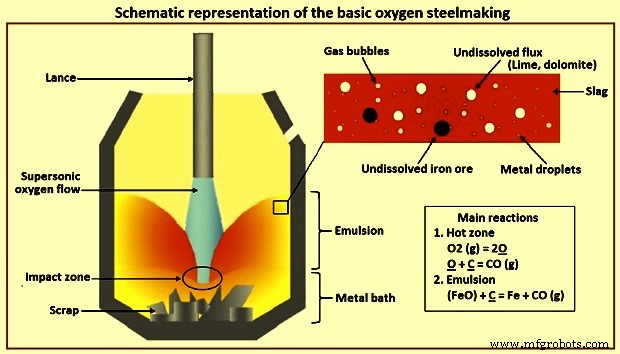
그림 1 기본 산소 제강의 개략도
탄소 산화 – Bath에서 이용 가능한 C의 탈탄은 BOS 공정 중 가장 광범위하고 중요한 반응입니다. 이 탈탄 반응에는 3가지 별개의 단계가 있습니다. 타격의 처음 몇 분 동안 발생하는 첫 번째 단계에서는 공급된 O2의 대부분이 수조의 Si와 반응하기 때문에 탈탄이 느린 속도로 발생합니다. 수조의 높은 C 함량에서 발생하는 두 번째 단계에서 탈탄은 더 높은 속도로 발생하며 공급된 O2의 속도로 제어됩니다. 세 번째 단계는 욕의 C 함량이 약 0.3%에 도달할 때 발생합니다. 이 단계에서 더 적은 C가 공급된 모든 O2와 반응할 수 있기 때문에 탈탄 속도가 떨어집니다. 이 단계에서 속도는 C의 물질이동에 의해 조절되며, O2는 대부분 철(Fe)과 반응하여 FeO를 형성한다. 이 단계에서 CO 발생률이 떨어지기 때문에 C가 약 0.1% 수준으로 떨어지면 변환기 입구의 불꽃이 덜 발광되고 실질적으로 사라집니다.
실리콘 산화 – 실리콘 산화에 유리한 조건은 (i) 저온, (ii) 슬래그 내 SiO2 양이 적습니다. 기본 슬래그는 Si 산화를 선호합니다. 염기성 슬래그에서 Si 산화는 SiO2가 CaO와 반응하여 슬래그 내 SiO2의 활성을 감소시키기 때문에 실질적으로 매우 낮은 값으로 발생한다. 거의 모든 Si는 Si에 대한 O2의 강한 친화력 때문에 타격 초기에 산화되고 제거됩니다. HM의 Si는 타격의 처음 3분에서 5분 동안 매우 낮은 수준(0.005% 미만)으로 산화됩니다. Si의 SiO2로의 산화는 발열 반응이며 수조 온도를 높이는 상당한 양의 열을 생성합니다. 또한 첨가된 석회 및 소성된 백운석과 반응하여 염기성 슬래그를 형성하는 규산염 슬래그를 형성합니다. Si의 산화가 주요 열원이기 때문에 HM의 양은 변환기에 추가할 수 있는 냉간 장입물(스크랩, 선철 등)의 양을 결정합니다. 이는 또한 슬래그의 부피를 결정하므로 욕의 탈인과 수율에 영향을 미칩니다. 경험에 따르면 슬래그 양이 많을수록 P는 낮아지지만 수율도 낮아집니다.
철 산화 – 철(Fe)의 산화는 (i) 슬래그의 FeO 함량 및 철강 내 O2 함량, (ii) 슬래그 내 Fe 손실을 제어하여 제강 생산성에 영향을 미치기 때문에 BOS 공정에서 가장 중요합니다. 공정, (iii) 슬래그의 산화 전위, (iv) FeO는 슬래그에서 CaO의 용해를 돕습니다.
망간 산화 – BOS 공정에서 Mn 산화 반응은 다소 복잡합니다. 탑 블로운 변환기에서 Mn은 블로우의 초기 단계에서 산화 MnO 산화물로 산화되고 대부분의 Si가 산화된 후 Mn은 수조 금속으로 되돌아갑니다. 마지막으로, 산화를 위해 더 많은 O2를 사용할 수 있게 되면 타격이 끝날 때 Mn은 도금욕 금속에서 환원됩니다. 전로에서 하부 취입 또는 복합 취입의 경우, Mn의 산화는 유사한 패턴을 갖지만 전로 배스 내 용강의 잔류 Mn 함량은 상부 취입 전로보다 높다.
인 산화 – 전로의 산화 조건은 도금욕 금속의 탈인에 유리합니다. 탈인 반응은 욕에서 금속과 슬래그의 상호 작용으로 인해 발생합니다. 더 낮은 수조 온도, 더 높은 슬래그 염기도(CaO/SiO2 비율), 더 높은 슬래그 내 FeO 함량, 더 높은 슬래그 유동성 및 수조의 양호한 교반과 같은 매개변수는 탈인 반응을 선호합니다. 욕 금속의 인 함량은 취입 초기에 감소한 다음 FeO가 환원되는 주요 탈탄 기간 동안 P가 욕 금속으로 되돌아가고 최종적으로 취입 종료 시 다시 감소합니다. 수조 교반은 금속과 슬래그의 혼합을 개선하고 탈인 속도를 돕습니다. 가루 스파 등과 같은 융제제를 첨가하여 잘 교반하면 CaO의 용해도를 증가시켜 인 제거를 개선하여 염기성 및 유동성 액체 슬래그를 생성합니다.
황 반응 – BOS 공정에서는 높은 산화 조건 때문에 S 제거가 그다지 효과적이지 않습니다. S분배율(슬래그 내 %S/금속 내 %S)은 4~8 정도로 2차 제강공정의 강국(300~500)보다 훨씬 낮다. BOS 공정 동안 수조에 있는 약 10% ~ 20%의 S가 O2와 직접 반응하여 SO2(이산화황)를 형성합니다. 나머지 S는 슬래그 – 금속 반응 S + CaO =CaS + FeO에 의해 제거됩니다. 슬래그에 의한 S 제거는 슬래그의 높은 염기도와 낮은 Fe 함량에 의해 지원됩니다. 액강의 S 함량은 HM에 함유된 S와 전로에 장입되는 스크랩의 영향을 크게 받습니다.
BOS 프로세스 동안 발생하는 반응은 이질적이며 다양한 길이 규모입니다. 벌크 금속욕상, 벌크 슬래그상 및 기체상이 있습니다. 한편, 대부분의 반응은 슬래그/금속/기체 에멀젼 상에 분포된 미세한 액적 및 기포의 규모에서 일어난다. 길이 척도의 차이는 또한 시간 척도의 차이를 초래합니다. 금속 수조는 12분에서 15분의 전체 열 주기에 걸쳐 변화를 보는 반면, 방울은 약 1분 안에 정제의 전체 주기를 거칠 수 있습니다. 따라서 공정 역학의 그림은 상업 및 파일럿 플랜트의 관찰 및 측정, 신중하게 설계된 실험 및 수학적 모델링을 기반으로 수년에 걸쳐 발전해 왔습니다.
HM의 일반적인 구성은 C – 4.5 %, Si – 0.3 % ~ 0.5 %, Mn – 0.2 % ~ 0.7 %, P – 0.1 % ~ 0.18 %, S – 0.02 % ~ 0.03 %, 온도 1,350 ℃입니다. S는 액체 철의 존재하에서 환원된 상태의 슬래그로만 제거될 수 있기 때문에, 염기성 산소 제강의 산화 공정은 상당한 양의 S를 제거하지 않습니다. 중요한 전체 반응은 다음과 같이 쓸 수 있습니다. [Si] + {O2} =(SiO2), (ii) [Mn] + 1/2{O2} =(MnO), (iii) [C] + 1/2 {O2} ={CO}, (iv ) 2[P] + 5/2{O2} =(P2O5), (v) Fe(l) + 1/2 O2(g) =(FeO). [-],{-} 및 (-)는 금속욕에 용해된 준금속, 가스 및 슬래그의 성분에 각각 사용됩니다. 그림 2a는 200t 변환기에서 반응의 진행 상황을 보여줍니다. 다른 변환기에서 수행된 측정도 유사한 패턴을 보여줍니다. 그림 2b는 이에 상응하는 슬래그 조성의 진화를 보여줍니다.
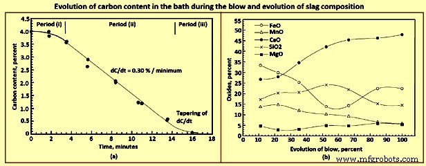
그림 2 블로우 중 수조의 탄소 함량 변화 및 슬래그 조성 변화
금속 조성의 진화에서 한 가지 주목할만한 특징은 Si가 매우 낮은 수준으로 떨어지기 전에도 상당한 양의 C를 동시에 제거한다는 것입니다. 이것은 또한 CO 화염이 O2 타격이 시작된 후 짧은 시간 내에 변환기 입구에서 분출된다는 관찰에 의해 입증됩니다. 이것은 현재 구식인 Bessemer 변환기 또는 OBM 공정에서 관찰된 것과 대조되며, 여기서 공기/O2가 바닥에서 불어옵니다. 이 두 공정에서 상당한 화염이 나타나는 데는 시간이 걸리며, 이는 Si가 상당히 낮은 값으로 떨어질 때까지 C 산화가 시작되지 않음을 나타내는 것으로 가정됩니다.
열역학적으로, 위에서 언급한 입력 조건에 대한 임의의 국부적 위치에서 용질 산화 반응의 순서는 Si, Mn, C 및 P입니다. 즉, 타격의 초기 부분에서 우세한 조건에서 Si는 이전에 산화됩니다. C. 낮은 초기 온도 자체가 Si 반응을 유리하게 만든다. 또한 제품 SiO2는 처음부터 유지되는 매우 기본적인 조건에서 매우 낮은 활성을 나타냅니다. 반면에 CO 분압은 거의 0.1MPa(1기압)으로 유지됩니다. 예를 들어, SiO2에 대한 활동도 0.001이 가정되면 4.5% C 및 0.5% Si와 평형을 이루는 pO2는 각각 1~1.7MPa 및 1~1.9MPa입니다. 이 기능은 프로세스 역학 및 반응 메커니즘의 분석을 흥미롭게 만듭니다.
프로세스의 특성
프로세스로부터의 피드백 정보는 제한적이기 때문에 얻을 수 있는 정보에서 관찰된 특성으로부터 프로세스 역학에 대한 모델을 구축해야 합니다. BOS 프로세스의 중요한 기능은 아래에 설명되어 있습니다.
반응 속도가 매우 빠릅니다. 피크 탈탄 동안 C는 분당 약 0.3%, 즉 200t 전로에서 분당 약 600kg의 C로 제거됩니다(그림 2a). C 반응은 세 가지 일반적인 기간(그림 2a), 즉 (i) 속도가 증가하는 초기 기간, (ii) 욕 내의 C 함량이 지속적으로 증가한다는 사실에도 불구하고 속도가 비교적 일정한 중간 기간을 보여줍니다. 이 기간 동안 약 3.5%에서 4.0%로 떨어지며, 비율이 감소할 때 임계 C 함량을 넘어서는 마지막 세 번째 기간입니다. 임계 C 함량은 일반적으로 0.2% ~ 0.5% 범위에 있습니다.
그러나 동일한 송풍 조건의 개별 가열은 광범위한 재현성을 보여줍니다. 입력 및 공정 매개변수가 동일한 두 개의 연속 타격은 슬로핑(전로 입구에서 비등하는 금속-슬래그-가스 에멀젼) 또는 건조 슬래그 및 침(랜스 및 입 축적을 초래)을 나타내는 일부 타격과 함께 상당히 다른 동작을 보일 수 있습니다. . BOS 공정의 초기에는 교반 가스의 바닥 분사가 아직 통합되지 않은 상태에서 재현성이 훨씬 더 만연했습니다. 절삭유로 스크랩을 적게 사용하면 재현성을 높이고 슬로핑을 줄일 수 있습니다.
여러 BOS 작업장에 대한 연구 후 피크 탈탄 속도는 O2 분사 속도에 정비례하는 것으로 나타났습니다. 또한 실험실 크기의 변환기에서 블로우 중에 O2 블로우 속도 증가 및 랜스 높이 감소가 피크 탈탄 속도에 미치는 영향이 유사하다는 것이 나타났습니다.
MEFOS(스웨덴 연구소)의 파일럿 전로에서 실험하는 동안 탑 블로운 전로의 높이에 따라 농도 변화가 있는 것으로 나타났습니다. 이것은 탑 제트의 엄청난 운동량에도 불구하고 탑 블로잉이 금속 수조를 잘 혼합하지 않는다는 것을 나타냅니다. 그러나 이 차이는 바닥에서 아주 소량의 불활성 가스를 불어넣으면 사라졌습니다.
BOS 공정에서 슬래그는 슬래그 단계에서 액적 형태의 금속의 상당 부분을 포함하는 것으로 잘 알려져 있습니다. 양은 타격 중에 다양하며 타격 중간 부분에서 가장 높습니다. 추정치는 10%에서 25% 범위에서 다양합니다. 이 방울은 대부분 1mm에서 2mm 미만으로 매우 미세합니다. 에멀젼의 방울 수는 타격이 끝날 때 감소합니다. 액적은 일반적으로 벌크 금속 배스에 비해 훨씬 더 고급 정제 상태에 있습니다.
대부분의 타격 동안 슬래그-금속-가스 에멀젼이 존재합니다. 타격의 약 1/3에 의해 유제 높이는 약 2m를 초과하여 랜스 팁을 잠기고 초음속 제트의 소리를 음소거합니다. 때로는 에멀젼이 용광로 전체를 채우고 입안에서 끓어 넘칠 수 있습니다(경사). 수조의 임계 C를 넘어 타격이 끝날 무렵, 에멀젼이 붕괴되어 에멀젼이 일시적인 상태임을 나타내며 생존을 위해 지속적인 가스 생성이 필요합니다.
언급한 바와 같이, C, Mn 및 P는 타격의 초기 부분에서 Si와 동시에 산화되며, Si 반응은 벌크 금속 욕 조성을 기반으로 하는 다른 반응보다 선호될 것으로 예상됩니다. Mn과 P 반응은 슬래그의 활동 사실에 의해 어느 정도 설명될 수 있습니다. 벌크 금속 조성이 반응 현장에서 우세하지 않다는 가설을 사용하지 않는 한 C 반응은 설명될 수 없습니다.
타격의 중간 부분에서 Mn과 P의 반전이 있습니다(그림 3a). 이는 슬래그 경로에도 반영됩니다(그림 2b). 그러나 복귀는 슬래그의 FeO 함량과 상관관계가 있음이 분명합니다. CaO의 용해는 초기 또는 타격 초기에 석회가 첨가되었음에도 불구하고 거의 끝까지 계속된다. C는 프로세스의 전체 역학을 결정하고 이 반응은 활발하게 발생합니다. 그림 3a는 블로우 동안의 용융 조성 변화를 보여줍니다.
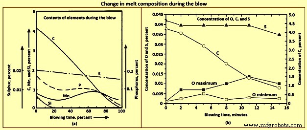
그림 3 블로우 중 용융 성분의 변화
역학 BOS 프로세스는 활발하게 일어나는 C 반응에 따라 달라집니다. 완전한 역학은 여러 사이트로 나눌 수 있습니다. 이 프레임워크에서 다른 반응을 이해할 수 있습니다. O2 제트는 거의 순수하기 때문에 분자는 상당한 물질 전달 장벽 없이 직접 수조 표면에 도달합니다. 분자가 충돌하면 다음 중 하나를 수행할 수 있습니다.
O2 분자는 충돌 지점에서 C와 반응합니다. 반응은 [C] + 1/2{O2} ={CO} 및 [C] + {O2} ={CO2}일 수 있습니다. 금속에 [O]로 용해될 수 있습니다. 그러면 이것은 다른 곳으로 이동하여 O2 =2[O]와 같은 다른 산화 가능한 원소와 반응할 수 있습니다. 그 중 일부는 수조에서 Fe와 반응하여 Fe + 1/2{O2} =(FeO) 방정식에 따라 FeO를 생성할 수 있습니다. FeO는 슬래그 상으로 이동하여 다른 곳에서 금속과 반응할 수 있습니다. 이들 각각은 전로의 다른 가능한 위치에서 정제 반응을 일으켜 혼합 시 전체 욕 정제로 이어집니다. 이러한 서로 다른 사이트는 그림 4에 개략적으로 표시되어 있습니다.
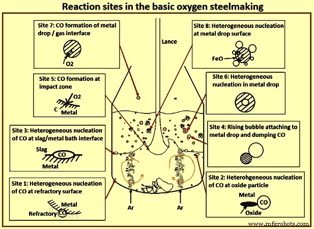
그림 4 기본 산소 제강의 반응 부위
C-O 반응은 이질적이라는 것을 기억해야 합니다. 속도 제한이 가능한 물질 전달 단계가 하나 이상 있습니다. C는 금속에서 계면으로 확산되어야 합니다. 기체상의 O2, 금속상의 용해된 O2, 또는 슬래그상의 FeO의 이동도 반응을 위한 O2 소스에 따라 관련될 수 있습니다. 용해된 O2는 금속 수조 내부의 다른 부분으로 이동할 수 있고 용해된 C와 반응하여 내화물(현장 1)의 가스로 채워진 기공으로 CO를 방출할 수 있습니다. CO는 또한 불균일 핵형성(사이트 2)에 의해 금속 수조에 떠 있는 고체 입자에 형성될 수 있습니다. 불균일 핵형성은 슬래그 층/금속 수조 계면(사이트 3)에서도 발생할 수 있습니다. CO 과포화도가 매우 높지 않은 경우 수조 내에서 균일한 핵 생성은 거의 불가능합니다. 앞서 설명한 바와 같이 CO 반응은 충돌 지점(현장 5)에서 직접 발생할 수 있습니다. 충돌 지점 또는 그 근처에서 형성된 FeO의 일부는 금속 수조 표면 아래로 들어가 슬래그/금속 계면을 따라 이동하여 C와 반응하여 유화 계면을 제공할 수 있습니다(현장 3에서와 같이). 그러나 형성된 FeO의 대부분은 아마도 슬래그 상으로 이동했을 것입니다.
이것은 이제 몇 가지 가능성을 제공합니다. 슬래그와 금속 수조 사이의 경계면에서 앞서 설명한 대로 반응이 일어날 수 있습니다(현장 3). 이제 O2는 슬래그 상에서, C는 금속에서 나옵니다. 앞서 설명한 바와 같이 슬래그 상은 많은 수의 금속 방울을 포함하며 충돌 지점에서 제트의 운동량에 의해 지속적으로 생성됩니다. 따라서 슬래그의 FeO2는 (i) CO 기포가 계면(사이트 8)에서 불균일하게 핵을 생성할 수 있고, (ii) CO가 액적(사이트 4) 및 (iii) CO 기포는 과포화도가 매우 높은 경우(사이트 6) 액적 내부에서 균일하게 핵을 생성할 수 있습니다. 금속 방울이 자유 판에 던지면 가스(사이트 7)의 O2 또는 CO2와 직접 반응할 수 있습니다.
이 모든 사이트는 타격 중에 어느 정도 활성화될 수 있지만 전체 역학을 결정하는 지배적인 메커니즘을 식별할 필요가 있습니다. 이러한 각 사이트의 기여도는 관찰을 기반으로 평가할 수 있습니다. 수조는 바닥 가스 주입이 없을 때 농도 구배를 나타내며, 이는 상부 가스 흐름과 비교하여 바닥에서 불어오는 불활성 가스의 1% 정도만으로 사라집니다. 사이트 1 및 사이트 2의 메커니즘 중요하지 않은 것으로 할인될 수 있습니다.
충돌 구역의 표면 온도는 2,120℃ 이상일 것으로 예상됩니다. 따라서 화학 반응 속도는 매우 높을 것으로 예상됩니다. 충돌 지점의 면적은 비교적 작고 O2 도달률은 매우 높습니다. 그러나 용질은 계면으로 확산되어야 하고 열은 금속으로 전도되어야 합니다. 신선한 금속은 큰 표면 속도로 바깥쪽으로 쓸려 나가는 인터페이스로 가져옵니다. 이러한 상황에서 충돌 표면은 O2와 반응하는 Fe 층 뒤에 남겨지는 용질이 부족할 것으로 예상할 수 있습니다. 궁극적으로 벌크 금속 조성의 금속 층이 완전히 산화되고 응축된 상 산화물이 슬래그 층으로 이동한다고 가정하는 것이 합리적일 수 있습니다. C 함량이 약 5%(20~25mol%)일 때 이 근사치는 공급된 O2의 약 25%가 이 사이트에서 C(CO 및 CO2)로 소비됨을 의미합니다. 기여도는 금속 측 질량 전달이 속도 제어가 아닌 것으로 가정한 계산에 기초하여 약 40%로 추정됩니다. 한때 그것은 주요 메커니즘(핫 존 또는 충돌 존 이론)으로 간주되었습니다. 이 사이트에서 바깥쪽으로 흐르는 금속층도 앞서 언급한 것처럼 O2로 포화될 수 있습니다.
에멀젼의 반응은 주요 반응 부위(부위 4, 6, 8)를 포함하는 것 같습니다. 에멀젼의 액적은 매우 큰 비표면적을 가지고 있습니다. 슬래그에 적당한 양의 Fe2O가 있는 경우 액적의 모든 정제 반응이 몇 분이 아닌 수십 초 만에 일어날 수 있습니다. 4.5% C를 함유한 3mm의 금속 방울은 부피 CO의 약 3,000배를 방출할 수 있습니다. 이것이 점성 슬래그를 통해 빠져나가면서 이를 유화시킵니다. 따라서 에멀젼 형성, 액적 생성, 액적 체류 시간 등의 복잡한 상호 작용은 전반적인 역학에 크게 기여합니다. 기체 상태와 직접적으로 반응하는 액적의 반응은 완전한 슬래그 층이 아직 형성되지 않은 타격의 처음 몇 분 동안 주로 중요합니다.
이 전체 공정 역학을 종합적으로 살펴보려면 초음속 가스 제트, 금속/슬래그 수조와의 상호 작용, 액적 생성 및 체류 시간, CaO 용해 및 수조 혼합 등에 대한 배경 지식이 필요합니다.
가스 중 가스 제트는 주변 가스를 주변에 동반합니다. 교란된 층은 흐름이 자기 유사한 반경 속도 프로파일로 완전히 발달되는 것을 넘어서는 하류에서 노즐 직경의 몇 개(잠재적 코어 영역)에 도달하는 제트 축에 도달합니다. 축방향 속도는 운동량 보존을 유지하기 위해 거리에 반비례합니다. 일반적으로 주변 가스가 제트 가스의 밀도와 동일한 경우 제트는 약 10도에서 12도 사이의 반원뿔 각도로 팽창합니다. 주변이 가벼우면 질량 효과로 인해 팽창이 적습니다.
초음속 제트에서 압축성 계수는 제트 팽창에 영향을 미칩니다. 제트는 축방향 속도가 음속(초음속 코어)으로 감속될 때까지 크게 팽창하지 않는 것으로 나타났습니다. 그 후 제트는 그림 5와 같이 아음속 제트로 확장됩니다. BOS 변환기로의 O2 제트에 대한 최근 CFD(전산 유체 역학) 연구는 축 방향 속도가 약 1m의 거리와 온도에 대해 거의 일정하다는 것을 보여주었습니다. 축의 가스는 이 영역에서 약 -170℃로 유지됩니다. 그 후 온도는 뜨거운 가스의 동반으로 인해 꾸준히 증가합니다. 따라서 O2 랜스는 약 2의 출구 마하 수에서 작동하므로 어느 정도 거리를 유지하면서도 여전히 좋은 제트/금속 상호 작용에 영향을 미칠 수 있습니다.
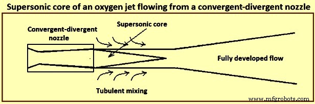
그림 5 수렴-발산 노즐에서 흐르는 산소 제트의 초음속 코어
BOS 변환기에서와 같이 O2 제트가 CO 대기에 잠기면 O2 농도가 상당히 낮아질 수 있음을 알 수 있습니다.
고속 제트가 금속 표면에 부딪히면 크레이터가 형성되며, 편향된 제트의 고속으로 인해 가장자리가 매우 불안정하여 금속 방울을 던집니다. 충분히 높은 값에서 제트는 재진입하게 되며, 여기서 일부 액적은 제트 자체에 던져져 매우 불안정한 분화구가 진동하고 회전합니다. In the presence of a slag layer these droplets are trapped by the slag leading to droplet-in-slag emulsion.
The crater depth can be calculated by performing a momentum balance at the stagnation point at the centre of the crater. In further studies with a constant based on the experiments with various liquids and gases at room temperature and quantitatively studying the emulsification phenomena with the help of a 2-dimension, two phase model of mercury and glycerol, it has been found, as expected, that the droplets in the emulsion are increased with gas flow rate and varies inversely with stand-off distance of the lance tip from the liquid surface (lance height). While experimenting with a 3-dimension model of water to determine the droplet generation rate with a top layer representing slag, it has been found that there are two regions, one at a lower flow rate where the rate increases nonlinearly with flow rate and the second where the rate varies almost linearly with the flow rate. The Weber number has been used to characterize the flow phenomena. Droplet generation rate (kg/second) is correlated experimentally as a function of the blow number. It has been shown that simultaneous bottom gas injection can increase droplet generation especially when they are nearly coaxial with the top jet. The presence of slag phase can change the rate of generation substantially.
In a supersonic jet, say of Mach 2, the exit gas temperature is around -100 deg C. Thereafter, it entrains lower density converter gas. The temperature, velocity, and composition of the gas change as the jet strikes the bath. Hence this correlation has large uncertainties, because of which usefulness of the correlation in the BOS model is less than adequate. Since there is no other correlation, one normally uses the above correlation for generation of droplets and tunes it as needed.
The reaction rates also depend on the droplet sizes. Several studies have obtained emulsion samples from the working converters or laboratory hot models. These studies have found in general the sizes to be in the range of 0.05 mm to 3 mm. In a study experimenting with pig iron and O2, there were large chunks of liquids thrown out, which normally spend negligible quantity of time in the emulsion. Though these approximations and correlations are clearly inadequate, most models use these for lack of better correlations.
One of the studies found large quantities of metallic droplets in the foamy slag formed during high P iron refining. Another study made similar observations by collecting samples ejected through the tap hole in a 230 t converter and analyzing them. Several other studies have also made similar observation.
As mentioned earlier, the droplets are in various states of advanced refining, some of them being almost completely refined, though the bath still had considerable quantity of C. The fraction of metal in the emulsion has been estimated to be large, being almost 25 % of the bath weight. This corresponds to a surface area of around 40,000 square metres (sqm) if one assumes an average size of 1 mm for the droplets. It has been proposed in one of the studies that refining in the converter takes place primarily in the emulsion phase, the bath seeing refining by dilution from droplets falling back (emulsion theory). Emulsion in the converters refers to a slag-metal-gas system. One can visualize it as slag-gas foam in which metal droplets are distributed.
It has been also reported that several of the droplets display high O2 super-saturation and this has postulated that the finer droplets can have been generated by homogeneous nucleation of CO droplet bursting. Some droplets show evidences of being attached to gas bubbles and some are even hollow. There have been several experiments with magnetically levitated and freely falling droplets reacting with oxidizing gases. The results of these experiments are interesting. When the C content is high, one can see reactions taking place at the surface, as evidenced by CO burning. As the C content comes down, small droplets are thrown out indicating sub-surface nucleation. Further lower in C content, the droplets sometimes burst, indicating O2 super-saturation and nucleation deep within the droplet. Super-saturation to the extent of around 5 MPa (for equilibrium CO) had been reported at the time of droplet bursting.
In one of the studies, the residence time of the droplets in a converter has been measured by radioactive gold isotope tracer technique. The maximum residence time of droplets which are in advanced state of decarburization has been estimated to be around 2 minutes. Residence time calculated on the basis of free fall is of the order of a few seconds even while considering the slag to be emulsified to a much greater height. The high residence time hence needs an explanation.
Several experiments using X-rays for visualization of a single Fe-C droplet reacting in molten oxidizing slags have shown that the droplet gets buoyed up to the surface as soon as decarburization starts, and stays at the surface till the CO bubbling subsides. Further, it has been shown that the droplet residence time is dependent on bubble formation which keeps the droplet afloat.
There are two views on how the CO formation keeps the droplet buoyant. One of the studies has formulated a bloated droplet theory wherein CO forms homogeneously inside the droplet and this hollow droplet has a low apparent density, due to which it remains afloat. The other view is that the bubbles form heterogeneously at the droplet / slag interface and as long as the bubbles stay attached to the droplet they keep it afloat. The visual evidences from X-ray fluoroscopic studies cannot clearly distinguish between these two. The fact that there does not seem to be a nucleation barrier during vigorous deoxidation as evidenced by copious evolution of bubbles suggests interface nucleation.
At high C concentrations when C mass transfer within the drop is not rate controlling, the highest CO super-saturation is to be seen at the droplet surface. Hence, it can be expected that for the nucleation to take place heterogeneously at the surface, the bubble is to spend some time at the interface before detaching. Since there can be several bubbles attached, the droplet remains buoyed. As C falls to low values, nucleation at the interface becomes sporadic, and in periods when there is no bubble attached, O2 dissolves into the metal and diffuses in. Hence, the highest super-saturation region moves inward, first to sub-surface and then to deep inside the droplet. One can thus see sub-surface nucleation initially throwing out small droplets and then deep inside. These homogeneous nucleation events are probably sporadic, with a stochastic nature.
Simultaneously, the apparent density of the droplet with no or few bubbles is now high and it falls down into the metal bath. The critical C content when the droplet falls down depends on droplet size, the oxidizing potential of the slag (and the rate of mass transfer of FeO), and the sporadic nucleation event either at the surface or inside the droplet. Empirical work to correctly predict the critical C content is lacking. Evidence from levitated droplet experiments also point towards these series of events, though the stirring due to the electro-magnetic field makes the condition different from that in the converter especially with respect to mass transfer within the droplet.
In the context of converter, the droplet surface is continuously disturbed by the bubbles. This has two counteracting effects. Part of the droplet surface is covered by the gas bubble and is not available for mass transfer from the slag to the droplet. The droplet surface is also vigorously stirred by the formation and detachment of bubbles, enhancing mass transfer locally. Several indirect estimations have been made. In one of the studies, indirect estimation of mass transfer coefficient has been made for FeO in slag for P transfer rate in high temperature single droplet experiments, and the values obtained are between (10)−5 metres per second (m/s) and (10)−4 m/s . Another study estimated similar values. Proper experimental studies, both in cold and hot models, are necessary to get reasonable correlations in terms of dimensionless variables.
Though the slag is very well stirred in the converter due to the gas jet and a large quantity of gas passing through it, the metal bath in top blown converters is comparatively poorly mixed. Measurement of mixing time (t95 which is the time to get 95 % homogeneity) in top blown converter can be as high as 150 seconds (s) to 180 s, as compared with 10 s to 20 s in bottom blown OBM converters. This has consequence on the reaction dynamics, since the metal droplets are removed from the top layer and the refined droplets from the emulsion fall back at the top. Since much of the heat is also released in the slag, the slag and the droplets falling back are also hotter. There can also be composition and temperature stratification due to the scrap at the bottom slowly dissolving into the liquid metal.
High mixing times also correspond to high irreproducibility in mixing times, leading to irreproducible blow behaviour in the absence of bottom blowing. For example, a large eddy of liquid metal containing higher C from the bottom being brought to the surface of the metal bath can suddenly increase the rate of decarburization leading to instabilities. Hence, inert gas injection from the bottom of the converters to bring down the mixing time has become the standard practice.
Since the rate of bottom gas injection and the position of the porous elements through which the gas is introduced have a bearing on the reaction dynamics, it is necessary to quantify the mixing behaviour for quantitative predictions of composition and temperature evolution. A single average t95 value is inadequate for incorporation into a comprehensive model of the converter, since two different mixing curves can give the similar t90 (time to get 90 % homogeneity) and different t95 values. The compromise can hence be a two parameter model, based on estimation of two mixing times (t90 and t95). One can then idealize the metal bath as consisting of two stirred tank reactors (STR), exchanging metal continuously. The bottom part sees only scrap melting and the top part sees all other phenomena explained earlier. The two parameters of this model, ratio of reactor sizes and the metal exchange rate can then be fitted to the mixing times of the converter under various conditions of operation.
Formation of slag and dissolution of fluxes
Fluxes (lime and calcined dolomite) which are charged early in the blow dissolve with the developing oxides to form a liquid slag. The rate of dissolution of these fluxes strongly affects the slag-metal reactions occuring during the blow. At the beginning of the blow, the lance height above the bath is kept high which causes an initial slag rich in SiO2 and FeO. During this period large quantities of fluxes are charged in the converter. The lance is then lowered and the slag starts to foam at around one third of the blow due to the reduction of FeO in the slag in conjunction with CO formation. As the blow progresses, the CaO dissolves in the slag, and the active slag weight increases. After the blow has progressed around three fourth of the time, the FeO content in the slag increases because of a decrease in the rate of decarburization.
During the blow, the temperature of the liquid steel gradually increases from around 1,350 deg C to 1.650 deg C at turndown of the converter, and the slag temperature is around 50 deg C higher than that of the liquid steel. The slag at turndown can contain regions of undissolved lime mixed with the liquid slag, since the dissolution of lime is limited by the presence of dicalcium silicate (2CaO.SiO2) coating, which is solid at steelmaking temperatures and prevents rapid dissolution. The presence of MgO in the flux weakens this coating. Hence, earlier charging of MgO speeds up slag formation due to quicker solution of lime.
The converter needs to maintain a good fluid slag of high basicity (high CaO content) so that the large quantity of CO generated can be handled, and P can be removed efficiently. Hence, the converter operator tries to achieve a CaO / SiO2 ratio in excess of 3.0 in the final slag.
Fig 6a shows the liquidus contours in a CaO-SiO2-FeO ternary diagram. It is clearly seen that a CaO / SiO2 ratio which can be achieved in this system at 1,350 deg C, i.e. at the beginning of a blow this ratio is limited to around 1.6 to 1.7. Marginal improvement can take place with MgO additions (Fig 6b) and some Al2O3 coming from the carry over slag. In the final slag also at 1,650 deg C with 25 % to 30 % FeO, the maximum CaO / SiO2 remain less than 3.0. This is also borne out by the slag analyses which frequently show un-dissolved lime. Apart from the issue of solubility of CaO in the converter slags, the lime particles get passivated in the presence of highly siliceous slags. Since the CaO concentration is the highest at the surface of a dissolving lime particle, di-calcium silicate forms here. This compound is not only highly refractory but it forms an adherent layer retarding further dissolution.
A lime particle remaining undissolved for long at the high temperatures also sinters and becomes less reactive. One way of breaking the adherent layer is to have high FeO content in the slag. This is the reason for the practice of raised lance blowing in the first few minutes of the blow, when the FeO is built up to 25 % to 35 % or higher. Though the effect on solubility of CaO is marginal (Fig 6), this facilitates breaking of the adherent di-calcium silicate layer permitting further dissolution.
Additives like fluorspar (CaF2) can bring about this effect much more efficiently, though this is not an acceptable plant practice in recent times for various reasons. Fig 6 shows phase diagrams with Fig 6a showing liquidus isotherms of CaO-SiO2-FeO system and Fig 6b showing tffect of MgO addition on the liquidus.
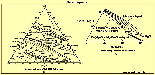
Fig 6 Phase diagrams
Process flow and reaction dynamics
The contents of the converter can be divided into several important regions such as (i) the metal bath, which itself can be divided into the bottom and top part between which there is exchange of metal, (ii) the O2 jet and the impact region, and (iii) the slag region which mostly is in the form of a slag-metal-gas emulsion. There are three distinct regimes in the blow. The initial part is characterized by a bare metal bath covered with islands of solid lime and some slag carried over from the previous heat. Jet of O2 hits the metal bath and does two primary things. First, it oxidizes almost an entire layer of the metal giving CO, SiO2, MnO, P2O5 and lots of FeO. Not all O2 is consumed in this location, and the gas above hence can contain high ratio of CO2 / CO and some O2 as seen in exhaust gas analysis. The jet also throws droplets into the gas phase, which after free flight fall back. Since the gas is oxidizing, the droplets get refined during the flight. At the surface of the droplets, the order of reactions is dictated by the thermodynamics.
For each of the solutes, reaction involves mass transfer steps such as mass transfer of CO2 / O2 in the gas phase and of the solutes in the liquid phase. The interfacial chemical reactions are expected to be very fast at this temperature. The order of the reactions can be achieved by solving the mass transfer equations along with free energy minimization for the interface reactions competing for O2. The order is normally Si and Mn followed by C and P. Since the time of flight is typically of the order of a second or lower, the droplets fall back probably completing only part of the Si reaction. Smaller the droplet, further the refining proceeds because of the larger specific surface area. Reaction at the rest of the surface of the metal bath is small because of the smaller surface area compared to that of the droplets.
The mass transfer in the gas phase can easily be calculated by Ranz-Marshall type correlations. At this initial phase of the process droplets are high in solutes, and the gas phase mass transfer is expected to be rate controlling. The small droplets can be considered as rigid and one can assume pure diffusion of solutes inside the droplets. When the droplets fall back, the condensed phase oxide products in the droplets remain at the top of the bath, and on combining with the oxides from the impact site and the fluxes added start forming a liquid slag. As mentioned earlier, good quantity of FeO is formed at the impact site, and hence liquid slag formation is easy. After sometime, there is a liquid slag layer covering the metal bath. Increasingly more and more droplets are thrown to the slag. The droplets ejected into the gas phase now have to pass through the slag phase before reaching the metal bath. Further refining hence takes place in the slag.
Initially when the slag layer is thin and the droplets are high enough in Si and Mn, the droplets fall through before the C reaction starts, that is, with no gas evolution, especially for larger droplets. Smaller droplets high in C can however start to decarburize early releasing CO, and slowly emulsifying the slag. This early phase is characterized by a low flame at the mouth, since CO formation is comparatively low. Once the Si in the metal bath falls down to some extent, the desiliconization progresses considerably, before the droplet has fallen down. C reaction starts and the droplet stays now buoyed in the emulsion till its C content reaches the critical C content as explained earlier. In the slag phase, the rate is expected to be controlled by slag phase mass transfer of FeO, as long as C in the droplet remains high enough. Once a critical C is reached in the droplet, bubbling slows down and then ceases, and the droplet falls down. The critical C is largely determined by the FeO content in the bath. Quickly the emulsion builds up and the second phase of reactions in the emulsion starts. The flame at the converter mouth becomes large. The lance tip gets dipped into the emulsion.
In the second phase almost all of the droplets are ejected into the emulsion, and the gas phase reactions become unimportant. It is to be noted that the residence times of the quiescent droplets in the slag are only of the order of a few seconds unless decarburization reaction starts. Hence, for maximizing the refining, the operator is to quickly reach a stage where the decarburization reaction starts before the droplets fall back. One way to accelerate the reactions is to keep the FeO content in the slag high. Another reason why FeO is to be increased as early as possible is to have a fluid slag by the time decarburization rate reaches its highest value, since the large quantity of gasses are to quickly escape from the slag. Else, the emulsion height gets build up uncontrollably leading to overflow, and slopping.
The FeO content in the slag is a balance between its generation at the point of impact and its consumption by the droplets in the emulsion. The FeO generation is probably weakly dependent of the lance height, whereas a high lance leads to less droplet generation due to lower force with which the jet strikes the metal bath, and vice versa. Hence a raised lance practice, called the soft blow, leads to quick increase in the FeO content in the slag. This facilitates CaO dissolution and formation of a fluid slag. The initial soft blow, normally 3 min to 4 min, is the normal plant practice.
At an optimum moment, the lance is lowered to induce high rates of reactions. Droplet generation rates are high, the bath is already desiliconized, and hence the droplets undergo vigorous decarburization till C goes to low values before falling back. During this period of peak decarburization rates, hence a large part of the metal bath remains in the emulsion as droplets. These droplets have spent different times in the emulsion and hence are in different stages of refinement. The degree of refinement also depends on the droplet size. The droplet are hence characterized by two variables namely the time it has been formed (and hence its age) and the size of the droplet. The droplet starts to fall back when a characteristic C content is reached, which depends on its size, the slag FeO, and the temperature. During this last phase of the droplets, the O2 potential at the interface is also high and hence P is also removed if other conditions are favourable. Falling droplets result in apparent refinement of the top of the metal bath, which on mixing lead to refinement of the rest of the bath. Since the time for refinement of a droplet can be of the order of 0.5 min to 2 min, one sees drop in C, Mn and P in the bulk metal sample even if Si in the sample is still of considerable quantity (Fig 3a).
The overall rate of reaction, to some extent, is self-correcting. If the number of droplets in the emulsion come down decreasing the rate, the level of the metal bath increases leading to lower effective lance distance, which in turn causes droplet generation to increase. This is one of the reasons for the near constant decarburization rate during middle part of the blow. It is however is to be noted that the C content of droplets entering into the emulsion keeps falling down, and hence their residence time. The operator is required to correspondingly increase the droplet generation rate by progressively lowering the lance. Fig 7a indicates the lance height variation during a typical blow.
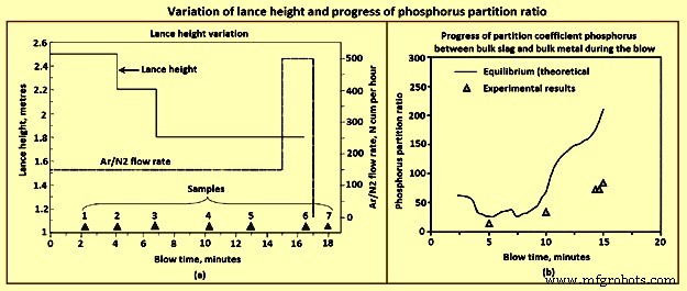
Fig 7 Variation of lance height and progress of phosphorus partition ratio
As the bath becomes low in C in the final phase of the blow, the rate now gets limited by C diffusion within the droplet even as it enters the emulsion. The CO generation is low and is not able to keep the droplets floated. The residence time drops down to a few seconds, and hence number of droplets in the emulsion comes down even though the lance height has been brought down to the lowest level permissible for lance health. The emulsion dies down. At this time there is falling rates of decarburization and fast buildup of FeO in the slag. Since the rates are low, the FeO content and the O2 dissolved in steel increase much beyond what is dictated by C-O equilibrium. Hence, at this period, the operator raises the argon stirring rate, increasing thereby the droplet generation rate without adding extra O2. This helps to some extent.
Phosphorus removal is sometimes an issue in the BOS process and can result in re-blows, especially when the input P in the hot metal is high (around 0.2 %). Though the conditions are normally favourable in the final slag with high FeO and high basicity, the converter operator can land in adverse situation if the slag regime is not carefully managed throughout the blow. The thermodynamics of P is well known. The reaction is written either in terms of molecular species or in the ionic form. The reaction is 2P + 5/2 O2(g) =P2O5(l), P + 5/4 O2(g) + 3/2 (O)2− =(PO4)3−. In the former case one writes an equilibrium constant, and expresses the Raoultian activity coefficient as a function of slag composition. If one adopts an ionic form of the equation, one instead writes an equation for a phosphate capacity of slag and correlates the phosphate capacity to the slag composition empirically. Both these approaches are conceptually similar. The partial pressures of P and O2 can easily be converted to percent dissolved in metal or activity of FeO in slag with known thermodynamic data. The slag data as a function of composition either as Raoultian activity coefficient or as phosphate capacity have been empirically determined in several studies. The progress of partition coefficient for P between bulk slag and bulk metal can be calculated when the slag analysis during the blow is known.
In the initial period of the blow, the bath C is quite high and also contains Si. Hence at the slag / metal interface, the O2 potential remains low. Therefore, very high rate of dephosphorization at the bulk metal / slag interface is not expected. The metal droplets, on the other hand, get highly refined in a matter of 1 min to 2 min, and before returning to the metal bath, have high O2 potential at its interface. Further the partition coefficient at this time is high since FeO content is high due to soft blow, temperature is low, although with some CaO yet to dissolve. The number of droplets in the emulsion is also very large. Hence, the dephosphorization rate is very high which can be seen in Fig 3a. Towards the end of the blow again, the conditions in the slag are favourable with high FeO and high basicity, though now the temperature has risen substantially. The rate of phosphorus removal however is not very high in this period, since the number of droplets is not very high, surface area is quite small and hence all reactions are slow.
Vigorous Ar stirring is helpful at this time of the blow, and for some time after the O2 flow is stopped, though to a limited extent. It is in the middle part of the blow the operator has the highest opportunity for efficient overall dephosphorization. After the soft blow when the lance is lowered progressively for effecting high rates of decarburization, FeO content in the slag drops considerably and remains low till the emulsion starts collapsing. The slag becomes comparatively ‘dry.’ The partition coefficient becomes adverse, and one can easily get P reversal to the metal. Lower is the FeO level, higher is the reversal. This reversal increases the load on the last part of the blow where the rates of reactions are anyway low as explained earlier.
Hence, close control of the FeO content during the middle part of the blow is necessary if the operator is required to make low P steel. Premature lowering of the lance in each stage can lead to very low FeO content (less than 12 % to 15 %). FeO content is determined by the balance between droplet generation rate (consumption rate) and the FeO generation rate. However, it is to be noted that very low FeO in the slag also lowers the decarbonization rate. Very high FeO on the other hand leads to sloppy conditions.
Higher levels of FeO content can be achieved by modifying the lance practice. The lance height for the intermediate levels can be kept slightly higher than the normal. The operator can also slightly delay lowering of the lance, taking care to see that it does not lead to uncontrolled emulsion build up. The operator can also achieve this by distributed ore addition during this period.
The chemistry of steelmaking in BOS converter is summarized here. From the thermodynamics of the O2 steelmaking process, it can be seen that, at the beginning, the O2 blown onto the HM preferably reacts with the dissolved Si, forming SiO2 which floats on the surface of the metal. From kinetics, it is expected that a part of the O2 blown reacts with the dissolved C and Fe atoms. The formation of CO gas occurs instantaneously on process ignition. Calcined lime is added to neutralize the acid slag, which initially includes a liquid mixture of FexOy and SiO2. Several chemical reactions take place in the BOS converter. The main reactions are dissolution of O2 into the metal from O2 gas, decarburization through dissolved O2, and oxidation of Fe, [Si], [Mn], [P], [V] and [Ti]. Solid or liquid oxides are formed as reaction products during blowing, and they are bound with the lime which is added at the start of blowing to form a liquid slag in the converter. Due to intensive CO gas formation, droplets of liquid metal are introduced into the slag, which tends to foam. Hence, the slag in the converter during O2 blowing is actually an emulsion of liquid slag and metal droplets, foaming because of the influence of gas bubbles. The emulsion is also a favourable site for reactions. For example, a considerable fraction of C oxidation can occur in the metal droplets in the emulsion although the majority takes place in the impact zone of the O2 jets. The rest of the O2 is used to burn Fe into FexOy. During blowing, O2 penetrates the metal droplets and can react with the CO gas. The total slag-gas system behaves as foam and rises quickly to the cone of the converter. Hence, the O2 inflow and the reaction rates have to be adjusted so that foam is not spilled from the converter. Slopping frequently occurs even though the inner volume of the converter is almost nine times larger than the volume of the inactive metal and slag bath.
제조공정
기본 산소로에서 슬래그의 발포 BOF(Basic Oxygen Furnace) 제강에서는 초음속 산소(O2) 흐름이 뜨거운 금속 수조 표면에 주입됩니다. 탄소(C), 규소(Si), 망간(Mn), 인(P)과 같은 욕 내의 불순물 원소는 CO(일산화탄소), CO2(탄소 다이옥사이드), SiO2(실리카), MnO(산화망간), P2O5(오산화인), 산화철은 주입된 O2에 의해 제거된다. 90% CO 및 10% CO2를 포함하는 기체 산화물은 소량의 산화철(FeO) 및 석회(CaO) 먼지와 함께 상부에서 용광로를 빠져 나옵니다. 다른 액체
기본 산소로에서 슬래그의 경사 BOF(Basic Oxygen Furnace)에서의 제강은 강철이 액체 철로 만들어지는 배치 공정입니다. 탄소(C), 망간(Mn), 인(P)과 같은 원소의 농도는 철강 품질에 영향을 미칩니다. 강철을 주조하려면 미리 정의된 온도에 있어야 합니다. 미리 정의된 온도와 구성을 달성하기 위해 산소(O2)가 액체 철을 포함하는 내화 라이닝 전환기로 불어넣어집니다. O2는 수조 내의 다른 원소를 산화시켜 온도를 증가시키고 바람직하지 않은 원소의 농도를 감소시킵니다. 형성된 액체 산화물은 슬래그 층을 형성