

제조공정

산업 제조
연속 주조 공정의 전자기 교반
액강의 연속주조 공정에서는 주강 제품의 품질을 향상시키는 방법이 항상 중요합니다. 이것은 또한 프로세스의 개발을 위해 중요하게 남아 있습니다. 제트유동각을 수정하고 SEN(침수진입노즐) 형상을 재작성하는 것 외에도 유동제어기법으로 액강과 교반기의 접촉 없이 유체의 흐름을 제어할 수 있는 전자기기법을 사용하고 있다. 전자기 기술의 한 유형은 선형 유도 모터가 제공하는 로렌츠 힘에 의해 유체 흐름을 생성하는 전자기 교반(EMS)입니다. EMS 기술은 몇 년 동안 강철의 연속 주조에 사용되었지만 적용 효과와 액체 코어 교반의 후속 이점은 단면 크기, 강철 등급 및 제품 적용에 크게 좌우됩니다.
구서독의 융한스(Junghans)사의 시험용 연속주조기에서 강재에 연속주조 원리를 최초로 적용한 이후로 연속주조 제품의 품질에 대한 관심이 높아지고 있다. 최근 몇 년 동안 청정 강 생산에 대한 스트레스로 인해 주조 제품의 미세 구조 및 조성 균질화에 대한 요구 사항이 높아졌습니다. 화학 조성, 응고 조건 및 금형 내 용강 흐름의 특성은 주조 제품의 표면 품질과 내부 구조에 영향을 미칩니다. EMS 기술의 적용은 가닥에서 등축 결정 영역의 형성을 촉진합니다. 응고조직의 미세화, 개재물의 함량저하, 주조품의 표면, 하부표면 및 내부구조의 품질향상을 가져온다.
연속 주조 공정에서는 액강이 금형에 주입됩니다. 최종 강철 쉘은 몰드에서 시작하여 스트랜드에서 계속되는 응고 후에 얻어집니다. 교반기 및 제동기와 같은 전자기 장치는 최종 주조 제품의 품질과 주조 속도를 모두 향상시키는 데 사용되는 잘 알려진 기술입니다. 미세 구조 및 표면 균열 측면에서 최종 쉘의 주요 결함은 온도 변화, 액강의 속도 및 압력, 자유 표면 거동 및 주요 원인 중 일부인 슬래그 비말동반과 같은 금형 내 현상과 직접적으로 관련될 수 있습니다. 최종 제품의 결함. 연속 주조기에도 사용되는 또 다른 유형의 전자기 장치가 있으며 이를 전자기 제동(EMBR)이라고 합니다. 이 장치는 대부분 금형에 설치되며 선형 EMS와 유사하지만 교류가 아닌 직류를 사용합니다.
EMS는 액강의 연속 주조에서 응고 과정을 제어하기 위한 직접적이고 강력한 기술입니다. EMS의 유일한 장점은 아니지만 중요한 장점은 주조 제품의 중심선에서 품질과 구조 및 화학의 균일성이 향상된다는 것입니다. 생산성 이점은 품질 향상을 수반합니다. 실험 결과는 예를 들어 등축 영역 너비를 증가시켜 강철의 미세 구조에 대한 EMS의 유익한 효과를 보여주었습니다. 가닥의 여러 유형의 결함은 EMS를 적용하여 크기를 효과적으로 줄일 수 있습니다. 기포와 다공성도 EMS에 의해 상당한 영향을 받을 것으로 예상됩니다. 또한 EMS는 연속 주조 공정의 수율과 생산성을 증가시킨다고 보고됩니다.
연속 주조 공정에 EMS를 적용한 것은 비교적 오랜 역사를 가지고 있으며 EMS의 첫 시도는 1960년대로 거슬러 올라갑니다. EMS는 연속 주조 공정이 산업적으로 강철을 생산하기 시작한 지 약 10년 후에 연속 주조기에 도입되었습니다. EMS는 내포물과 기포에도 영향을 미치는 것으로 나타났습니다. Strand EMS는 1970년대 후반 연속주조기에 EMS를 본격적으로 적용하는 문을 열었습니다. 스트랜드 EMS의 목적은 중심편석을 억제할 목적으로 높은 등축대비를 얻는 것이다. 그 후, 인몰드 EMS(그림 1)는 응고된 쉘에 비금속 개재물 및 아르곤 기포의 포획을 억제하여 주강 제품의 표면 품질을 개선하기 위해 개발되었습니다.
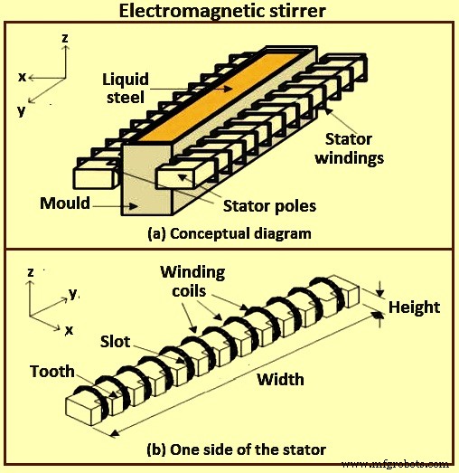
그림 1 전자기 교반기
연속 주조 공정의 높은 생산성을 달성하기 위해 EMBR은 연속 주조 금형에서 액강 흐름을 안정화하기 위해 1980년대에 개발되었습니다. EMBR의 첫 번째 유형은 SEN 포트 근처에 한 쌍의 DC(직류) 자석이 설치된 로컬 자기장을 생성하는 것입니다. 부과된 필드는 SEN에서 직접 배출되는 흐름을 '제동'합니다. 두 번째 유형의 EMBR은 금형 폭 방향으로 균일한 자기장이 자기장 영역 아래에서 플러그와 같은 흐름을 발생시키는 레벨 자기장입니다. 두 번째 유형의 EMBR의 한 종류는 흐름 제어(FC) 금형(연속 주조 금형의 상부에 한 쌍의 수평 자기장을 부과하여 금형의 좁은 면을 따라 메니스커스 흐름과 하강 흐름을 동시에 안정화합니다. ). 현재 EMS와 EMBR의 조합도 개발되었습니다.
공정을 제어하고 최종 제품의 불량을 방지하기 위해 EMS, EMBR과 같은 전자기 장치로 공정을 개선했습니다. 주요 차이점은 교반기가 AC(교류) 전류 공급 하에서 작동하고 역학 자기장을 생성한다는 것입니다. 제동기는 DC(직류) 전류에 의해 공급되는 영구 자석 또는 회로입니다. 따라서 그들은 일정한 자기장을 생성합니다. 차이점에도 불구하고 금속 흐름에 자기장의 중첩이 프로세스 설계에 따라 흐름을 구동할 수 있는 로렌츠 힘을 생성한다는 동일한 아이디어를 기반으로 합니다. 금형에서 발생하는 물리적 현상은 액체 흐름, 다상 해석, 전자기 계산, 열 전달 및 응고 과정을 포함하는 다중 물리학 문제이며 이러한 각 물리학은 서로 의존합니다.
고체든 유체든 도체에 적용된 교류 자기장(단상 또는 다상)은 도체에 전류를 유도하여 로렌츠 힘 분포를 유도한다는 것은 잘 알려져 있습니다. 이 로렌츠 힘은 일반적으로 회전하며 도체가 유체이면 움직이게 됩니다. 따라서 자기장은 방해가 되지 않는 교반 장치로 작용하며 원칙적으로 원하는 교반 패턴을 제공하도록 설계될 수 있습니다. 교반은 유체를 통해 구동되는 정상 전류 분포와 관련 자기장의 상호 작용을 통해서도 영향을 받을 수 있습니다. 필드 주파수가 높을 때 로렌츠 힘은 얇은 전자기 경계층에 국한되고 자기장의 순 효과는 경계층 바로 내부에 접선 속도 또는 접선 응력을 유도하는 것입니다. 속도 또는 응력의 분포는 적용된 필드의 구조와 관련이 있습니다. 대칭 구성은 유선형 표면에 유선형이 있는 교반 패턴으로 이어질 수 있지만 더 일반적으로 유선형 패턴은 혼란스럽습니다.
금형 영역의 흐름은 노즐 및 금형 형상, 주조 속도, 노즐 잠김 깊이, 아르곤 가스 주입 및 전자기력 적용에 의해 제어됩니다. 전자기력은 선택적으로 스트랜드의 두께를 통해 정적 또는 이동 자기장으로 적용됩니다. 정적(DC) 전자기장은 전도성 액체 강철에 전류를 유도하고, 이는 차례로 흐름에 직접 반대되는 힘을 생성하므로 '브레이크' 또는 'EMBR'이라고 합니다. EMBR 필드에는 로컬 원통형 필드, 전체 금형 폭에 걸친 넓은 '자 모양' 자기장, 이중 눈금자 필드(때로는 '흐름 제어' 또는 'FC 몰드' 필드라고도 함)가 포함됩니다.
전자기력은 다른 주조 조건, 노즐 및 금형 형상과 결합하여 금형의 유체 흐름을 제어하는 중요한 도구입니다. 방법에는 정적 자기장(로컬 및 눈금자 EMBR)과 EMS, 다중 모드 EMS, EMLS(전자기 준위 안정기) 및 EMLA(전자기 준위 가속기)와 같은 시변 자기장이 포함됩니다. 최적의 사용은 흐름을 안정화시켜 표면 결함을 줄이고 개재물을 줄이며 미세 구조를 개선할 수 있습니다.
이동(AC) 필드는 전자기 교반(EMS)에서 비롯되며, 여러 일련의 자기에서 필드를 위상 이동하여 순 필드가 가닥의 반대쪽에서 반대 방향으로 이동하도록 하여 일반적으로 횡방향 평면에서 회전 흐름을 유도합니다. 몰드(M-EMS) 또는 전자기 회전 교반(EMRS). '다중 모드 EMS'라고도 하는 필드를 같은 방향으로 움직이게 하면 가속 흐름(EMLA) 또는 감속 흐름(EMLS)을 유발할 수 있습니다. 전자기력은 유도된 힘이 액체강 흐름의 강도에 따라 변하기 때문에 다른 흐름 제어 매개변수에 비해 이점을 제공하여 시스템이 난류 흐름 변화에 대해 자체 안정화되는 이론적 능력을 제공합니다. 실제로는 달성하기 어렵습니다.
EMS의 원리
EMS는 리니어 모터의 원리를 이용합니다. 액체강에 닿는 부분이 없는 비접촉식 교반기라는 점에서 기존의 기계식 감압식과 다릅니다. 그림 2a와 같이 화로 바닥에 코일이 설치되어 있어 이 코일(인덕터)에 3상 교류 전압을 인가하면 움직이는 자기장(H)을 발생시킨다. 자기장의 작용으로 인해 액체강에 전력이 생성되고 흐름에 유도 전류(I)가 발생합니다(플레밍의 오른손 법칙). 이 전류는 인덕터의 자기장과 함께 작용하여 Fleming의 왼손 법칙에 따라 액체강에 전자기력(F)을 유도합니다. 이 힘을 로렌츠 힘이라고 합니다.
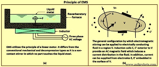
그림 2 EMS의 원리
회전식 전자기 교반기는 비동기식 모터 고정자와 동일합니다. 일반적으로 3상 또는 때로는 2상 주파수 변환기에 의해 공급됩니다. 회전하는 자기장이 생성되며, 액체강 내부의 변화는 자기장과 상호 작용하여 힘(로렌츠 힘)을 생성하는 와전류를 생성합니다. 최종 결과는 강철 회전을 유도하는 토크의 발생입니다. 생성된 토크는 (i) 공급된 전류의 강도, (ii) 코일을 형성하는 권선 수, (iii) 주파수, (iv) 시스템 기하학과 같은 여러 요인에 따라 달라집니다. 이러한 매개변수는 교반기 유형 M-EMS(금형 전자기 교반기), S-EMS(스트랜드 전자기 교반기) 및 (iii) F-EMS(최종 전자기 교반기)에 따라 변경됩니다.
따라서 자기장은 방해가 되지 않는 교반 장치로 작용하며 원칙적으로 원하는 교반 패턴을 제공하도록 설계될 수 있습니다. 교반기 디자인, 크기 및 위치 등은 연속 주조기 데이터, 생산할 강종 및 주조 매개변수에 따라 다릅니다.
EMS 시스템은 속도가 v인 B에 수직인 방향으로 와전류 j를 유도하는 B의 유도로 회전하는 자기 유도장을 생성합니다. 유도 B와 전류 j는 강철의 모든 부피 단위에 작용하는 전자기력을 생성합니다. 그리고 액체 강철에 교반 운동을 가져옵니다. 벡터 곱(v x B)은 전자기장과 액체강의 흐름 사이의 연결을 보여줍니다. EMS로 인한 액강의 속도는 초당 0.1미터(m/s)에서 1.0미터/초 사이입니다.
전류 j(x,t)가 자기장 B,(x,t)가 있는 상태에서 고체든 유체든 전도체를 통해 흐를 때 단위 부피당 힘 F(로렌츠 힘)가 주어집니다. 도체에 작용하는 방정식 F=j x B에 의해. 일반적으로 이 힘은 회전합니다. 즉, 컬 F는 0이 아니며 도체가 유체인 경우 압력 구배로 보상할 수 없습니다. 이러한 상황에서 유체는 힘에 반응하여 움직여야 합니다. 이것은 가장 간단한 용어로 전자기 교반의 원리입니다.
표면이 S인 제한된 부피 V에 제한된 비압축성 액체를 고려하여 V+를 외부 영역이라고 합니다. 도체 내에서 B와 j는 암페어의 법칙(Mo)j =curl B, V x B =0에 의해 관련되며, 여기서 Mo =4(pi) x (10)-7(SI 단위)입니다. 자기장은 외부 도메인 V+에 있는 코일의 전류(AC 또는 DC)와 같은 외부 소스를 가질 수도 있습니다. 고려할 수 있는 정상적인 상황은 그림 2b에 스케치되어 있습니다. 외부 코일 C, C'의 전류는 패러데이의 법칙을 통해 도체에 전류 분포를 유도합니다. 이 전류는 경계 S에 내장된 전극 E, E' 사이의 전위차를 직접 적용하여 증가될 수 있습니다. 따라서 전류는 시간 종속 자기장 또는 전기적으로 또는 둘 다를 적용하여 유도될 수 있습니다. 매우 광범위한 물리적 조건과 특히 야금 가공 분야에서 동등하게 광범위한 응용을 고려할 수 있습니다.
이러한 응용 프로그램 중 일부의 실질적인 중요성과 EMS의 기본 원칙이 잘 이해되고 있다는 사실에도 불구하고 가장 이상적인 상황을 제외한 모든 환경에서 EMS가 생성하는 흐름에 대한 이해는 여전히 상당히 원시적인 수준입니다.
EMS 카테고리
EMS는 주조기의 설치 위치에 따라 분류할 수 있습니다. 설치 위치와 야금학적 측면에 따라 모든 전자기 교반기는 세 가지 유형으로 분류할 수 있습니다. 위치 및 주강 제품에 필요한 영향에 따라 이러한 세 가지 가능한 교반기 적용은 (i) M-EMS, (ii) S-EMS) 및 (iii) F-EMS입니다. M-EMS는 이름에서 알 수 있듯이 금형에 있습니다. 인몰드 교반(일차 EMS라고도 함)입니다. S-EMS는 2차 냉각 영역의 금형 아래에 있습니다. 많은 비율의 액강이 남아 있는 금형 아래의 교반입니다(2차 EMS 또는 금형 아래 교반이라고도 함). FEMS는 야금 길이의 끝에 위치합니다(응고가 완료되기 직전). 최종 응고 지점 직전의 교반입니다(최종 EMS라고 함). 그림 3은 세 가지 주요 교반 유형을 보여줍니다.
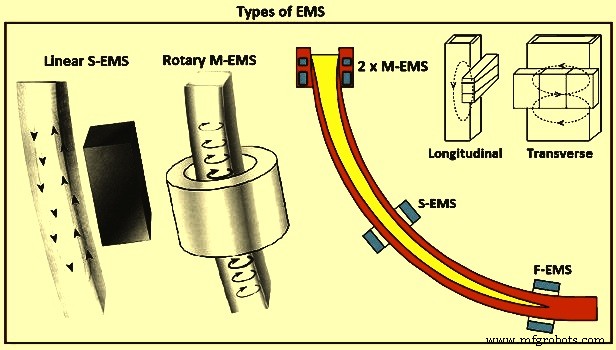
그림 3 EMS 유형
M-EMS – 회전식 M-EMS는 일반적으로 빌렛/블룸 교반 장비를 선택할 때 첫 번째 선택입니다. 생성된 회전 자기장은 액체강에 원형 운동을 제공합니다(그림 3). 중심 등축대는 회전 흐름이 기둥 모양의 수상 돌기 팁의 골절을 촉진하고 중심 영역에서 등축 결정 형성을 위한 핵 역할을 하기 때문에 확대됩니다. 또한, 회전 흐름은 응고 전면을 플러시하여 개재물 및 기포가 갇히는 것을 방지합니다. 더욱이, 발달된 원심력으로 인해 더 가벼운 단계가 생성됩니다(즉, 개재물 및 기포가 응고 전면에서 스트랜드의 중심을 향해 이동합니다.
선형 M-EMS는 더 큰 직사각형 스트랜드 섹션에 사용됩니다. 그런 다음 두 개의 교반기를 주조 제품의 넓은 면을 따라 수평으로 배치하고 회전 교반으로 얻은 이점과 유사합니다. M-EMS는 전통적으로 내부 설계로 금형에 내장되어 있었는데, 여기서 코일은 금형과 함께 캐스터에서 제거되었습니다. 각 금형 교환을 위해 전기 케이블과 가능하면 물 호스를 코일에 연결/분리해야 했습니다. 새로운 주조 기계는 코일이 주형 주위에 만들어지고 주형 교환 중에 주형에 남아 있는 외부 디자인을 가지고 있습니다.
M-EMS는 일반적으로 금형의 액강을 교반하기 위해 금형의 하부에 설치됩니다. 표면, 하부 표면 및 내부 가닥 품질을 향상시킵니다. M-EMS를 적용하면 핀홀, 중심 다공성 및 주조 제품의 편석이 감소합니다. 응고 구조를 개선하고 표면 거칠기를 줄이며 열 전달 속도를 높입니다. M-EMS는 원형 또는 사각 디자인으로 내부 또는 외부에 설치할 수 있습니다. 몰드 메니스커스에서 교반 속도의 유연한 제어를 제공하기 위해 이중 코일 M-EMS(그림 6)가 개발되었습니다. 이중 코일 M-EMS는 두 개의 독립적인 EMS로 구성됩니다. 상부 EMS는 메니스커스의 흐름 제어를 위한 것이고 하부 EMS는 주형의 주금속 교반을 수행합니다. 메니스커스에서 액체강 속도의 감소는 상부 EMS 자기장을 하부 EMS의 자기장과 반대 방향으로 회전시킴으로써 달성된다. 이러한 이중 M-EMS의 설계는 강 연속주조의 다양한 조건에서 EMS 기술을 사용할 수 있는 기회를 넓혀준다.
S-EMS – 선형 S-EMS에서 전자기 코일은 가닥의 한쪽을 따라 설치되고 가닥에서 수직 순환 액체 금속 흐름 패턴을 생성합니다(그림 3). 교반기는 가닥의 한쪽을 따라 배치되므로 매우 다양한 가닥 크기에 사용할 수 있습니다. 중심 등축 결정 영역의 증가는 회전식 교반기에 의해 얻은 것과 동일한 메커니즘에 의해 얻어진다. 일반적으로 곡면 주형 연속 주조기의 상부 표면에 가까운 밴드에 집중되어 있는 개재물도 더 균일하게 분포됩니다. 금형 아래 최적의 위치에 배치된 회전식 S-EMS는 브레이크아웃에 민감합니다.
S-EMS는 주물 폭을 따라 액강을 수평으로 밀어내는 교반력을 발생시키고 액강에 나비형 흐름 패턴을 생성합니다. S-EMS를 지지 롤러 뒤에 배치할 수 있는 경우(그림 4) 최소 지지 롤러 직경에 의존하지 않으므로 이 경우 야금학적 관점에서 가닥을 따라 최적으로 배치할 수 있습니다. 지지 롤러에 내장된 S-EMS는 철심과 권선을 포함하기 위해 최소 롤러 직경이 필요합니다. 이 경우 교반기는 메니스커스에서 멀리 떨어져 있으므로 덜 효과적입니다. S-EMS는 스트랜드를 통한 교반기 힘의 우수한 침투를 보장하기 위해 저주파에서 작동합니다. 그 결과, 액체강은 그림 3과 같이 횡방향 교반을 갖는다. S-EMS는 일반적으로 M-EMS와 조합하여 사용된다. S-EMS는 선형 또는 회전식 교반기일 수 있습니다. 가장 일반적으로 사용되는 선형 교반기는 설치가 쉽고 열 복사 및 가능한 이탈로부터 보호합니다. S-EMS는 등축 구조의 형성을 촉진합니다. 주조 제품의 결정립 미세화를 촉진하고 수축 공동, 중심 편석 및 내부 균열을 줄입니다. 또한 과열도를 효과적으로 제거합니다.
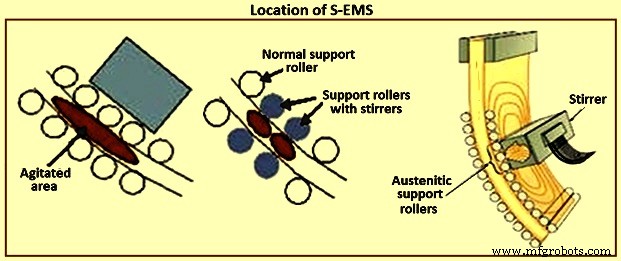
그림 4 S-EMS의 위치
F- EMS – 연속 주조 스트랜드의 최종 응고 영역에서 몰드 아래까지 교반하기 위해 EMS를 사용하는 데에도 마찬가지로 강한 관심이 있습니다. 그러나 기존의 EMS 시스템은 이 지역에 적용될 때 다소 비효율적인 것으로 입증되었습니다. 잠재적인 해결책으로, 최근 최종 영역에서 광범위하게 분포된 격렬한 교반을 개발하기 위해 변조된 로렌츠 힘을 적용하는 데 상당한 관심이 있었습니다. F-EMS는 일반적으로 M-EMS 또는 S-EMS와 함께 설치되어 중심 분리의 피크를 줄이고 차단합니다. F-EMS는 고탄소강 또는 고합금강 등급을 주조할 때 특히 효율적입니다. 또한 F-EMS의 사용으로 주조품의 응고구조가 개선되고 등축구조와 내부 기공률의 비율이 증가함을 알 수 있었다. 수축이 감소하고 중심 탄소 편석 비율이 감소합니다. 또한 SDAS(secondary dendrite arm spacing)가 개선되고 중심 등축 입자의 비율이 상당히 증가하여 입자가 더 미세해집니다. 따라서 F-EMS로 주조품의 품질이 향상됩니다.
기본적으로 연속 주조 '회전' 교반과 '상하'(또는 축) 교반에 적용되는 교반에는 두 가지 유형이 있습니다(그림 5). 최근에 이러한 유형의 교반에 대한 여러 버전이 많은 특허에서 제안되었으며 일부는 다른 것보다 더 정교하지만 모두 또는 거의 모두가 위에서 언급한 범주 중 하나로 분류될 수 있습니다.
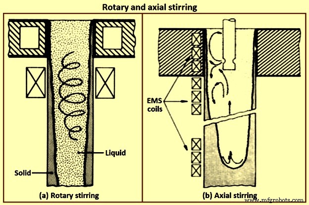
그림 5 회전 및 축 방향 교반
EMS의 전자기장은 선형 교반기, 회전 교반기 및 전도성 교반기를 포함하는 세 가지 방식으로 생성됩니다. 선형 교반기의 자극은 직선에 위치하고 회전 교반기의 자극은 원 위에 위치합니다. 선형 및 회전식 전자기 교반기 모두 AC를 사용하여 자기장과 원하는 효과를 생성합니다. 선형 및 회전식 전자기 교반기는 강철에 전류를 유도합니다. 반면에 전도성 교반은 전도 전류와 유도 전류를 사용하여 전자기장과 원하는 효과를 생성합니다. Rotary EMS는 금형과 2차 냉각 영역 모두에 설치되는 반면 Linear EMS는 S-EMS 장치로 주로 사용됩니다. 전도성 교반은 다른 두 가지 모드에 비해 틈새 시장입니다.
회전 교반 – 회전식 교반에 대한 최초의 작업은 오스트리아의 조사관 그룹에 의해 수행되었습니다. 둥근 주형에 주조된 빌렛을 주형 수준에서 또는 주형 바로 아래에서 교반했습니다. 실제로 금형은 회전식 교반이 의미가 있을 수 있는 유일한 영역입니다. 회전 방식으로 금형 아래에서 실질적으로 교반하면 해결할 수 있는 것보다 더 많은 문제가 발생할 수 있습니다. 언급한 바와 같이, 주형에서 라운드의 회전식 교반에는 약간의 장점이 있습니다. 주물 표면에서 고형 개재물이 제거되고 스트랜드의 단단한 외피가 금형과 더 잘 접촉하도록 하여 열 전달이 향상됩니다. 금형 내에서 회전 교반으로 피부가 파열될 위험이 없습니다. 그러나 회전식 교반의 주요 장점은 장비 설계가 쉽다는 것입니다. 오늘날 사용되는 거의 모든 전기 모터와 동일하기 때문에 전기 엔지니어는 이러한 유형의 전자기 유도 운동에 매우 익숙합니다.
회전 운동은 엔지니어링 설계상의 문제가 없지만 야금학적 관점에서 가장 좋은 유형의 운동은 아닐 수 있습니다. 회전식 교반의 기본적인 문제 중 하나는 액체가 원심력을 받게 되어 가벼운 성분(예:내포물)이 중심을 향해 분리되는 경향이 있다는 것입니다(그림 5). 이것은 액체의 속도에 상한선을 부과하며, 이는 반드시 '그림 프레임' 효과의 출현으로 설정된 동일한 한계가 아닙니다. 때로는 이음매 없는 파이프를 위한 라운드를 주조할 때와 같이 이러한 고려 사항을 무시할 수 있습니다. 그러나 더 융통성 없는 또 다른 제한 사항을 무시할 수 없습니다. 액체의 원형 속도를 높이면 고체 껍질에 대한 압력이 불균형하게 증가하여 파열될 수 있습니다. 이 위험은 인, 셀레늄 및 납과 같이 분리도가 높은 원소를 포함하는 강종을 주조할 때 특히 심각합니다. 이러한 구성 요소가 형성하는 저융점 액체는 수상돌기 사이의 공간을 차지하여 껍질이 가질 수 있는 강도를 감소시킵니다.
회전 방식으로 몰드 아래에서 교반할 때 발생하는 또 다른 바람직하지 않은 상황은 특히 한 레벨에서만 수행될 때 액체 풀을 교반 레벨 위의 상부(뜨거운) 부분과 하부의 두 부분으로 효과적으로 분리하는 것입니다. (차가운) 부분이 교반 수준보다 낮습니다. 풀의 자연스러운 흐름을 방해하는 것 외에도 이러한 분할은 브리징 문제를 일으킬 수 있습니다. 브리징은 회전식 교반이 금형 아래에만 적용되었을 때 최근에 보고된 몇 가지 문제에 의해 입증될 수 있는 것처럼 거시적 분리를 강화합니다. 이러한 문제는 특히 낮은 속도로 교반할 때 발생하기 쉽습니다. 교반 영역의 흐릿한 영역에서 분리된 큰 수상돌기 조각은 교반 강도가 낮기 때문에 크기를 줄일 수 없습니다. 이 큰 조각은 풀의 아래쪽(차가운) 부분으로 가라앉아 성장할 기회가 있고 클러스터를 형성하며 브리징을 유발합니다.
회전식 교반에는 또 다른 단점이 있을 수 있습니다. 초기 데이터는 EMS에 의해 강의 개재물 크기와 함량을 실질적으로 줄이기 위해 액체의 속도가 특정 하한을 초과해야 함을 나타냅니다. 예를 들어, AISI 4335 강 등급의 경우 이 한계는 0.5m/s 이상인 것으로 나타났습니다. 이는 깨끗한 스킨도 생성되는 대형 잉곳에서 리밍 작업 중에 발생하는 속도와 비슷합니다. 안전한 회전 액체 운동을 위해 앞서 언급한 상한선이 개재물 감소를 위한 고속 요구 사항과 충돌한다는 것은 거의 확실합니다. 새로운 응고 구조, 즉 섬유 구조 및 유동 수정 또는 탐니트 구조를 생성하는 경우에도 마찬가지이며, 이는 또한 높은 속도를 필요로 합니다. 일반적으로 품질 및 유도 교반에 대한 새로운 개발을 적극적으로 추구해 온 철강 산업 부문은 곧 고속 교반을 통해 이러한 구조를 추구할 수 있습니다.
축 방향 교반 – 축 방향 또는 '위아래' 버전의 교반은 응고 가닥의 액체 부분을 가닥의 축과 평행한 방향으로 이동하기 위해 제공되며, 이러한 유형의 유도 운동은 자연 발생, 열 유도, 대류 흐름 패턴. 금형 영역에는 자연 흐름을 역전시키는 이유가 있습니다. 강철의 연속 주조에서 금형 영역은 15m 이상 깊이가 될 수 있는 액체 풀의 작은 부분을 구성합니다(기계의 속도와 크기에 따라 다름). 몰드 아래에서 흐름은 솔리드 스킨에 인접하여 '아래로', 스트랜드 중심에서 '위로'입니다.
EMS의 '위아래' 버전은 야금학적 관점에서 가장 적합합니다. 액체의 속도는 이 기술에서 실질적으로 무제한이며 원하는 제어를 적용할 수 있는 충분한 자유를 제공합니다. 전자기적으로 유도된 힘은 액체를 고체 껍질에 대고 힘을 가하기보다는 액체를 포함하는 경향이 있기 때문에 브레이크 아웃의 위험이 최소화됩니다. 다른 주요 이점이 있습니다. 상단의 뜨거운 액체는 수영장의 바닥으로 빠르게 이동하여 껍질의 두께를 다소 줄이고 부드러운 영역 전체에서 높은 온도 구배를 유지하는 경향이 있습니다. 이 두 가지 효과는 열 흐름을 개선하여 연속 주조기의 생산성을 높이는 데 유용할 수 있습니다. 이 버전의 EMS로 생산성을 향상시킬 수 있는 또 다른 방법이 있습니다. 단단한 쉘의 윤곽은 둥근 바닥을 형성하도록 수정될 수 있고 풀의 깊이는 감소됩니다. 이것은 더 높은 캐스팅 속도를 허용합니다. 등온선이 변하고 스트랜드 중심에서 성장이 상향 성분이 증가하기 때문에 중심선 수축 및 분리의 범위도 줄일 수 있습니다.
마지막으로, 악명 높은 알루미나 클러스터와 같이 응고 중에 형성되는 개재물도 고체에 갇히지 않도록 하고 슬래그에 합류할 기회가 있는 풀의 상단으로 빠르게 휩쓸려갑니다(즉, 떠다니는 반월상 연골) 따라서 제거됩니다. 이러한 유형의 흐름은 구현하기가 다소 어렵습니다. 특히 교반이 야금학적 길이를 따라 상당한 부분에 걸쳐 적용되어야 하는 경우, 즉 '위아래' 교반의 연속 버전입니다. 그러나 이 경우의 어려움은 문제의 전기공학적 측면에 있다는 점을 강조해야 합니다. 코일 사이 또는 선형 모터를 형성하는 일련의 코일 끝에 나타나는 주요 섭동 없이 단방향 흐름을 구현하는 것은 상대적으로 어렵습니다. 이러한 이상은 주조 구조에서 양수 또는 음수 분리 밴드로 반영됩니다. 또한, '위 및 아래' 교반은 일반적으로 지지 롤이 없는 스트랜드의 상당히 넓은 영역을 필요로 하거나 사용되는 선형 모터의 필드를 방해하지 않도록 롤을 최소한 수정해야 합니다. 마지막으로, 이러한 유형의 교반에 사용되는 선형 모터는 주로 전자기 루프의 높은 저항(큰 에어 갭 및 단단한 금속 표면 갭)으로 인해 효율성이 매우 낮습니다(1% 이하).
간헐적으로 뒤집기 – 원래 일부 일본 조사관에 의해 회전식 교반 모드의 변형이 제안되었습니다. 이 기술은 등축 영역의 크기를 향상시키는 흐름 방향을 간헐적으로 역전시키는 것을 제공합니다. 회전식 교반에 대한 위의 논의는 몇 가지 추가 조건과 함께 여기에 적용됩니다. 간헐적 운동은 에너지를 낭비하지만 EMS의 한 가지 목적을 달성하는 장점이 있어 기둥 성장을 좌절시킨다. 교반 시 역류는 국부적 난류 세포에서 전단에 의해 수상 돌기를 더 작은 조각으로 깰 수 있을 뿐만 아니라 이러한 수상 돌기가 항상 흐름(상류)으로 성장하려고 하기 때문에 기둥 모양 수상 돌기의 단방향 성장을 방해할 수 있습니다. 그러나 EMS의 다른 가능한 이점이 이 기술로 파생될 수 있는지는 의심스럽습니다.
전자기 교반이 주강 제품의 품질에 미치는 영향
화학 조성, 응고 조건 및 금형 내 액체강 흐름의 특성은 본질적으로 스트랜드의 표면 품질과 내부 구조에 영향을 미칩니다. 스트랜드 형성 과정에는 주형과 2차 냉각 구역(SCZ)에서 액강의 응고가 포함됩니다. 회전하거나 이동하는 자기장은 액체의 흐름 특성에 영향을 미치고 열-질량 전달 과정을 강화합니다. 스트랜드 품질에 대한 전자기 교반의 영향 정도는 EMS의 기술적 특성과 연속 주조 굽힘 축을 따른 배열에 따라 다릅니다. EMS는 금형, SCZ 및 최종 응고 구역(FCZ)에 성공적으로 설치할 수 있습니다.
For improving the surface, subsurface, and inner strand quality, the liquid steel stirring has to take place in the mould. M-EMS is either of round or square design and it can be installed internally or externally. The result of applying M-EMS is a reduction in centre porosity and segregation in the cast product. To provide flexible control of stirring speed in the mould meniscus, the dual-coil M-EMS (Fig 6) has been developed. It consists of two independent EMS. The upper EMS is intended for flow control in the meniscus. The lower EMS performs the main metal stirring in the mould. The reduction in metal speed in the meniscus is achieved by rotating the upper EMS magnetic field in the opposite direction to that of the lower EMS. Such an M-EMS design widens the opportunities for using the technique under various conditions of continuous casting of liquid steel.
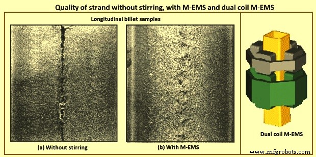
Fig 6 Quality of strand without stirring, with SMS, and dual coil M-EMS
The application of electromagnetic stirring of steels promotes the formation of an equiaxed crystallic zone in the strand. The stirring improves strand quality, even in steel casting with overheating. To further reduce and cut peaks in centre segregation, F-EMS, in combination with M-EMS or S-EMS, has to be used. F-EMS is particularly efficient when casting high carbon or high alloy steel grades. F-EMS and M-EMS combinations reduce the areas with the highest carbon content, where cementite and martensite otherwise can form. It has been found that stainless steels, solidifying with primary ferrite, have a sound centre at a reduction ratio of 3.6 when using S-EMS and F-EMS. The application of S-EMS increases the equiaxed crystallic zone instead of columnar structure and reduces cracks in the steel strand. The benefits available by using one or more EMS in combination are listed in Tab 1.
| Tab 1 Benefits available with using one or more EMS | ||||||
| M-EMS | M-EMS + F-EMS | M-EMS + S-EMS + F-EMS | M-EMS + S-EMS | S-EMS | S-EMS + F-EMS | |
| Pinhole and blowhole | +++ | +++ | +++ | +++ | – | – |
| Surface and subsurface cracks | +++ | +++ | +++ | +++ | – | – |
| Breakout reduction | ++ | ++ | ++ | ++ | +* | +* |
| Surface cracks (round) | ++ | ++ | ++ | ++ | – | – |
| Solidification structure and internal cracks | ++ | ++ | +++ | ++ | +** | +** |
| Centre line segregation, and centre porosity | ++ | +++ | +++ | ++ | ++ | +++ |
| V segregation | + | +++ | +++ | ++ | +*** | ++ |
| * S-EMS in high position | ||||||
| ** Better structure only in centre part of the product, after position of S-EMS, worse structure in external part compared to application of M-EMS. Risks of negative segregation when excessive stirring applied. | ||||||
| *** with S-EMS in low position | ||||||
For more demanding qualities the use of EMS can be justified when the costs of the quality defects, conditioning or rejections, or the costs of casting larger sections are too large. Rotary stirring is used for carbon steel with carbon less than 0.2 %. In some cases, in-mould stirring is preferred than the secondary stirring since in the secondary stirring the negative segregation is found. In-fact negative segregation does not have any effect on the mechanical properties but one minor exception is that it can cause local variation in the hardenability which is not appreciated. Carbon content between 0.2 % and 0.5 %, two-stage stirring is used. It is better to complement the in-mould stirring with the secondary stirring or final stirring. For carbon content higher than 0.5 % and alloy steels with a large solidification range, three-stage stirring is used.
Any benefits from EMS for slabs can be negated from the poor geometry. So, care is to be taken for the machining. Method of reducing submerged nozzle convection currents with the EMBR for improving cleanness. This consists of two sets of coils placed along the outer walls of the mould faces. The magnetic field reduces the liquid steel velocity and impurities float to the surface where they are trapped by the mould powder. The roll gap geometry of bloom casters and more considerably slab casters can have a major influence on the internal quality of continuous cast semis and on various types of segregation and consequently the increased levels of some elements in these segregated areas. The main types of segregation caused by deviations from the true roll gaps are (i) inter columnar macro segregation, (ii) centre line macro segregation, and (iii) off centre line semi macro segregation (also termed V segregation or spot segregation).
In the temperature range 1,300 deg C up to the solidus the ductility of steel is very low. This is due to the liquid phases of FeS and MnS which have segregated to the boundaries between dendrites. FeS and MnS both have melting points much lower than steel and hence these weak boundaries open at quite low tensile strains.
One of the metallurgical problems found in continuously cast products is the development of large columnar dendritic zones. The effect of columnar growth on the mechanical properties such as loss of ductility in steel has been investigated by Weiser. Alberney, have shown that centre line defects in the continuous casting can be considerably reduced by controlling the columnar growth regions. The control of columnar growth is crucial in producing good quality strand cast products.
Essentially, induction stirring causes a sweeping flow along the solid-liquid interface which affects the final solidification structure since it influences the local growth conditions such as the temperature gradient, the boundary layer thickness, and the structure and size of the ‘mushy zone’. Since macro-segregation is known to result from inter-dendritic fluid flow, reduction in the length of the ‘mushy zone is to effectively reduce the extent of macro-segregation, particularly along the centre line. Several studies have shown that EMS is an effective means of improving continuously cast steel solidification structures by preventing columnar growth.
The size of columnar zones and associated inter-dendritic segregation and shrinkage porosity are greatly reduced by the use of in-strand or in-mould electromagnetic stirring. The latter technique effectively increases the size of the equi-axed solidification zone and greatly reduces the amount of centre line shrinkage (Fig 6). The relative size of columnar and equiaxed zones in a cast cross section are also affected by superheating of liquid steel. High superheating in unstirred billets increases the size of the columnar zone because the nucleation of equiaxed dendrites is retarded. EMS reduces the effects of high superheats but does not completely compensate for the increased size of columnar zones developed by high superheat temperatures.
Superheat was one of the most fundamental factors recognized from the early years of continuous casting especially for medium and high carbon steels. In an early report, pilot plant tests were performed casting 150 mm x 150 mm billets of high carbon steels. It was proven that at low superheats or even sub-liquidus temperatures of casting, the centre line segregation was minimized. The electromagnetic stirring at the mould (M-EMS) exhibited some benefits, and the application of EMS at the strand (S) and final (F) stages of solidification started being installed in some casters. It was found that the combination of EMS, that is, (S+F)-EMS for blooms and (M+S+F)-EMS for billets, is the most effective method for reducing macro-segregation among various EMS conditions, causing them to solidify more rapidly during the final stages of solidification, providing more finely distributed porosities and segregation spots along the central region. The optimum liquid pool thickness was found to decrease as the carbon content increased, which can be attributed to longer solidification times in the solid fraction (fs) range from fs=0.3 to 0.7. The effect of superheat on the solidification structure has been analyzed, verifying the empirical fact that increasing superheat the columnar dendritic growth increases against the equiaxed one. They concluded that convection effects influenced micro-segregation behaviour of the studied high carbon (C less than or equal to 0.7 %), and high manganese steels.
The effect of F-EMS parameters with current intensity increasing from 300 A (ampere) to 400 A and frequency increasing from 4 Hz (hertz) to 12 Hz, on the electromagnetic forces and carbon concentration distribution in the central cross section of 70 steel square billet has been studied. The optimal F-EMS parameter to make uniform the central cross-sectional carbon concentration and minimize the centre carbon segregation of 70 steel billets has been obtained with a current intensity of 280 A and frequency of 12 Hz. Under this stirring parameter, the carbon segregation indexes for all sampling points are in the range of 0.92–1.05, which is attributed to the fact that its stirring intensity is more suitable for decreasing the strand centre temperature and increasing the solidification rate of the billet. Hence, the rejected solute element has limited time to transport after electromagnetic stirring which promotes the reduction of centre segregation.
It is well known that porosities and shrinkage cavity occur in the central part of continuous cast blooms and billets. Although there are good results in carbon segregation levels at a stirring current and frequency of 280 A and 12 Hz, respectively, further investigations have shown that the F-EMS has a considerable impact on the other internal qualities of a square billet.
The effect of F-EMS parameters on centre segregation was studied in 140 mm × 140 mm billet continuous casting process. In the model, the initial growth of equiaxed grains which can move freely with liquid was treated as slurry, while the coherent equiaxed zone was regarded as porous media. The results show that the stirring velocity is not the main factor influencing centre segregation improvement, which is more affected by current intensity and stirring pool width. Because solute transport is controlled by solidification rate as stirring pool width, centre segregation declines continuously with current intensity increasing. As liquid pool width decreases and less latent heat needs to dissipate in the later solidification, the centre segregation can be improved more obviously by F-EMS. Due to centre liquid solute enrichment and liquid phase accumulation in the stirring zone, centre segregation turns to rise reversely with higher current intensity and becomes more serious with stirring pool width further decreasing, it forms positive segregation and solute can be concentrate with weak stirring, leading to centre segregation deterioration. With the optimized current intensity, centre segregation improvement is better with respect to F-EMS.
Some F-EMS stirring techniques are more effective than others in terms of structure morphological transformation from original dendritic to globulitic and in its refining. Macrostructure of casts without the use of stirring is different from the one with the use of stirring. The structure can be obtained with conventional stirring is largely globule-shaped with some presence of dendrites and dendrite fragments. The structure obtained with modulated stirring consists of entirely globule-shaped crystals and structure appears to be more refined.
Grain size can be varied by applying different stirring setting. With F-EMS conventional stirring, the grain diameter is reduced in both cast mid radius and in central area with comparison with the unstirred structure. A further grain diameter reduction has been achieved with counter-rotating modulated and unmodulated stirring. However, the smallest grain diameter in the casts has been obtained with unidirectional modulated stirring, in comparison with the grain diameter in the cast without stirring.
In general, the microstructure of samples using F-EMS consists of globules and elongated grains in the structure obtained with stirring, and fine inter-granular eutectic network containing different compounds. The coarse dendritic structure of the cast products cast without stirring can be transformed into mainly globular one with some rosette shaped as a result of the conventional stirring application. The structure obtained with unidirectional modulated stirring consists of a mixture of fine round-shape globules and large elongated grains. This structure also appears to be more refined in comparison with that obtained with the conventional stirring.
The globule mean area and length in the microstructure of the combined mid-radius and centre area of the cast obtained with conventional stirring is when compared with the structure of the other casts. The globule mean area in the structure can be reduced, but not in case of structure obtained without stirring. The structure obtained with unidirectional modulated stirring in the casts, the globule mean area in these casts is reduced in comparison with conventional stirring. A similar trend is determined in reduction of the globule length. Concurrent with globule size reduction, their density has increased. The effect of the M-EMS on the solidification structures has been obtained under fixed superheat, casting speed, secondary cooling intensity, and M-EMS frequency. The ratio of the central equiaxed grain zone was found to increase with decreasing superheat, increasing casting speed, decreasing secondary cooling intensity, and increasing M-EMS current. But the equiaxed zone is limited for M-EMS, since it has more responsibility towards columnar zone. The grain size obviously decreased with decreasing superheat and increasing M-EMS current but was less sensitive to the casting speed and secondary cooling intensity.
White band segregation – The increasing use of electromagnetic stirring (EMS) over recent years has brought with it increased interest in the problem known as white bands. The white band is a zone of negative segregation (appearing white on sulphur prints) frequently found in S-EMS stirred products and corresponding to the position of the solidification front during stirring. The visual appearance of segregation has not only given rise to the name but is probably also the white band’s most undesirable feature. The extent of negative segregation at the white band is less than the positive segregation at the centre line, but it is continued presence after hot working can result in a deterrent to customer acceptance, mostly on cosmetic grounds. Kor has suggested an explanation, in which the white band is the result of changes in growth rate at the start and end of strand stirring. White band is due to the solute washing mechanism which was firstly found by Bridge and Rogers. This proposes that the turbulent flows caused by EMS penetrate the dendrite mesh and sweep out enriched inter-dendritic liquid (Fig 7). However, in order to maintain this action it is necessary to assume that the removed solute is very rapidly dispersed throughout the remaining liquid. This being so, it is difficult then to explain the observed solute enrichment at the end of stirring.
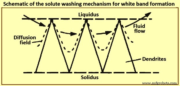
Fig 7 Schematic of the solute washing mechanism for white band formation
Mathematical modelling
In tandem, mathematical modelling has played an important role in the implementation of EMS, as regards to providing a deeper understanding of the effects of stirring on, for example, the heat and fluid flow. A series of studies by Schwerdtfeger and co-workers have formed the cornerstone of the modelling in this area. Specifically, they have explored, both experimentally and theoretically, the effect of stirring in the round billet, rectangular bloom and slab geometries which are characteristic for the continuous casting of steel. These models consist of the Navier Stokes equations for the velocity field of the liquid metal and Maxwell’s equations for the induced magnetic flux density. In principle, these are two-way coupled, since the alternating magnetic field gives rise to a Lorentz force which drives the velocity field. This, in turn, can affect the magnetic field. Moreover, the frequency of the magnetic field is typically large enough to allow the use of the time-averaged value of the Lorentz force as input to the Navier Stokes equations.
Recent study by Vynnycky revisited the problem of a rotary EMS applied to round-billet continuous casting and found that the method used originally to determine the components of the Lorentz force led to a non-unique solution. This has been a consequence of the fact that the normal component of the induced magnetic flux density, rather than the tangential ones, has been prescribed as the boundary condition. Moreover, since the normal component has been prescribed in models for the case of longitudinal stirring for rectangular blooms also, it is natural to expect non-uniqueness in those models too. Furthermore, since the expressions for the components of the Lorentz force are still frequently used, it is clear that a resolution of the issue is still timely, especially in view of modern-day interest in modulated EMS. In this case, magnetic fields of different frequencies are applied and it is the intention that the resulting Lorentz force is to have a constant time-averaged part and a time varying one. It goes without saying that posing the correct boundary conditions for the magnetic field is important for achieving meaningful results from modelling.
Since the early industrial implementation of EMS, it has been recognized that demanding steel grades, especially those with a wide solidification range, benefit from stirring both within the casting mould and also at a later solidification stage. This type of stirring, in continuous casting of liquid steel, became known as final solidification zone stirring or F-EMS. Despite early reports on F-EMS effectiveness with respect to improving the cast strand internal quality, especially the structural soundness and segregation, in the long run it has been realized that the metallurgical performance of F-EMS lacked in both the effectiveness and consistency, which can be attributed to a number of defining factors. First, it is important to position the F-EMS with respect to the solidification stage which corresponds to a certain solid fraction level in the melt volume. Second, the stirring at this solidification stage is being performed under conditions of progressively diminishing stirring torque and increasing melt viscosity. The former occurs due to a reduction of the stirring pool radius, while the latter is due to an increase in the solid fraction of the melt.
There is also an additional important factor impacting on the stirring effectiveness, arising due to the nature of the magnetic field used for stirring. The stirring systems currently employed in the production of continuously cast steel products are based on application of a rotating magnetic field (RMF). Such fields have limitations in their application at a later, or advanced, solidification stage, arising from the fact that the resulting angular velocity is very nearly constant with respect to radial position. This flow pattern is characterized by intensive shear force and turbulence at the solid-liquid interface which is highly effective in terms of dendrite fragmentation and the subsequent development of an equi-axial solidification structure, but has very little impact on mixing in the melt volume, especially near its central region. In contrast, intensive turbulence and mixing throughout the melt volume is required at a late solidification stage in order to disrupt formation of the crystalline network and, associated with it, the development onset of structural defects such as porosity, fissures, and solutal segregation.
There have been numerous developments aimed at improvement of the RMF based stirring at a later solidification stage through enhancement of the secondary fluid flow in the radial-axial plane. Hence, intermittent and alternating stirring schemes, both of which use sequential forced and dormant periods, have been introduced in the 1980s. Kojima and co-workers, demonstrated experimentally, while Davidson and Boysan confirmed theoretically that strong recirculatory flow occurs in the radial-axial directions during the dormant periods (i.e. without active stirring) due to the initial axial gradient of the swirl flow.
However, these stirring methods have not resulted in a considerable improvement of F-EMS performance. The reasons for that can be found in the recent study by S Eckert and co-workers who have shown that the occurrence of strong recirculatory flows is contingent on a provision of a narrow range of stirring and casting parameters. Non-compliance with those provisions can negatively impact on stirring performance and even render it useless or harmful. There have been several recent attempts to intensify turbulence and mixing in the bulk of the solidifying melt by using modulated electric currents to energize the stirring coils. The objective is to produce a modulated electromagnetic field which consists of both a time-averaged and a time-varying component. These recent developments have been theoretical and laboratory-scale in nature and none has been implemented into production practice. Counter-rotating magnetic fields have also been tested for stirring a solidifying aluminum alloy in laboratory experiments conducted by Vives. Considerable improvements in solidification structure have been achieved by using this stirring method.
Advantages of EMS
Advantages of EMS in the final product depend on the application and some examples are (i) better hot workability, during extrusion forging of the bars the frequency of internal failures is lower, (ii) improved shearing ability by avoiding the structure which causes cracks, (iii) improved hardenability because of improved homogeneity, (iv) improved wire rod drawing performances with a low frequency of cup and cone breakages, and (v) higher and more consistent fatigue properties of bars.
제조공정
다이캐스팅은 용융된 합금액을 압력챔버에 붓고, 금형의 캐비티를 고속으로 채우고, 합금액을 압력하에 응고시켜 주물을 형성하는 주조법이다. 다른 주조 방식과 구별되는 다이캐스팅의 주요 특징은 고압입니다. 및 고속 . 다이캐스팅 제품의 생산은 다이캐스팅 장비를 사용하여 완성되어야 합니다. 다이캐스팅 장비의 기술 수준이 제품의 품질과 수준을 결정합니다. 이 문서에서는 비용에 대해 설명합니다. 다이캐스팅 제조공정의 각 공정별로 작업시간을 단축하고, 생산원가를 절감하며, 효율성을 높입니다. 다음과 같이 다이캐스팅 제조 공정의 비용에 영향
다이 캐스팅은 금속 주조 공정입니다. 용융 금속에 고압을 가하기 위해 금형 캐비티를 사용하는 것이 특징입니다. 금형은 일반적으로 사출 성형과 유사한 고강도 합금으로 가공됩니다. 대부분의 다이캐스팅은 아연, 구리, 알루미늄, 마그네슘, 납, 주석 및 납-주석 합금과 같은 비철금속 및 이들의 합금으로 만들어집니다. 다이캐스팅의 종류에 따라 콜드챔버 다이캐스팅 머신 또는 핫챔버 다이캐스팅 머신이 필요합니다. 이 게시물의 주요 주제는 제조 과정입니다. 다이캐스팅의. 다이캐스팅 공정에 대한 포괄적인 이해를 돕기 위해 기본 2 다이캐스팅