

제조공정

산업 제조
인장 시험 중 철 및 강철 재료의 거동
철과 강철의 기계적 성질은 종종 인장 시험을 통해 평가됩니다. 테스트 기술은 잘 표준화되어 있으며 최소한의 장비로 경제적으로 수행할 수 있습니다. 철 및 강재는 구조용으로 사용되기 때문에 관련 규정 및 표준의 요구사항을 충족하는 인장 특성을 가져야 합니다. 코드 및 표준의 이러한 요구 사항은 최소 강도 및 연성 수준입니다. 이 때문에 인장 시험에서 얻을 수 있는 정보는 종종 제대로 활용되지 않습니다. 그러나 인장 시험 결과에 영향을 미치는 많은 야금학적 상호 작용을 직접 조사하면 시험 데이터의 유용성을 상당히 향상시킬 수 있습니다. 이러한 상호 작용을 조사하고 열처리, 표면 마감, 테스트 환경, 응력 상태 및 예상되는 열-기계적 노출과 같은 야금/재료/응용 변수와의 상관 관계는 효율성과 활용 품질 모두에서 상당한 개선으로 이어질 수 있습니다. 엔지니어링 응용 분야의 철 및 강철 재료.
철 및 강철 재료의 인장 시험은 여러 가지 이유로 수행됩니다. 인장 특성은 일반적으로 품질을 보장하기 위해 재료 사양에 포함되며 일축 인장 이외의 다른 형태의 하중 동안 이러한 재료의 거동을 예측하는 데 자주 사용됩니다. 인장 시험의 결과는 일반적으로 엔지니어링 용도로 이러한 재료를 선택하는 데 사용됩니다. 엔지니어링 응용 프로그램에서 이러한 재료의 선택, 자격 및 활용을 위한 기계적 특성 데이터를 개발하기 위한 비교적 쉽고 저렴한 기술을 제공합니다. 이 데이터는 일반적으로 특정 응용 분야에 대한 이러한 재료의 적합성을 확인하고 다른 대체 재료와의 비교를 위한 기초를 제공하는 데 사용됩니다.
철 및 강철 재료의 탄성 계수는 테스트 샘플이 늘어나는 속도(변형률)에 따라 달라집니다. 지정된 양의 소성 변형이 발생하는 항복 강도(YS) 또는 응력도 시험 변형 속도에 따라 달라집니다. 재료 구성, 입자 크기, 이전 변형, 테스트 온도 및 열처리도 측정된 YS에 영향을 줄 수 있습니다. 일반적으로 YS를 증가시키는 요인은 소성 변형을 방해하기 때문에 인장 연성을 감소시킵니다. 그러나 이러한 경향의 주목할만한 예외는 입자 크기가 감소할 때 YS의 증가와 함께 연성 증가입니다.
인장 시험 중 파손될 때까지 변형된 여러 구조 재료는 연성 공정에 의해 파손됩니다. 파단면은 미세 공극의 결합 또는 결합에 의해 형성됩니다. 이러한 미세 공극은 일반적으로 소성 변형 과정에서 핵을 생성하고 소성 변형 과정이 고도로 국지화 된 후에 유착이 시작됩니다. 변형률, 시험 온도 및 미세 구조는 유착 과정에 영향을 미치며 선택된 조건(예:온도 감소)에서 파괴는 연성에서 취성 과정으로 전환될 수 있습니다. 이러한 전환은 강도 측정에서 알아차리지 못할 수 있는 이러한 재료의 유용성을 제한할 수 있습니다.
철강 재료의 탄성 거동
철 및 강철 구조물은 일반적으로 건설에 사용되는 재료가 정상적인 사용 조건에서 탄성 하중을 받도록 설계됩니다. 이러한 하중은 재료에 탄성 또는 가역적 변형을 생성합니다. 강한 바람에 고층 강철 건물이 흔들리는 것은 탄성 변형률을 쉽게 볼 수 있는 예입니다. 자동차 차축이 구부러지고 차량이 지나갈 때 다리가 늘어나는 것은 덜 눈에 띄는 탄성 변형의 예입니다. 변형의 크기는 하중을 지지하는 재료의 탄성 계수에 따라 다릅니다. 탄성 계수는 일반적으로 인장 시험에 의해 결정되지 않지만 인장 거동은 철 및 강철 재료의 선택 및 사용에서 탄성 특성의 중요성을 보여주는 데 사용할 수 있습니다.
철(Fe)(207GPa)의 영률은 구리(Cu)(117GPa)의 거의 2배, 알루미늄(Al)(69GPa)의 약 3배입니다. 영률 값이 더 높기 때문에 Fe로 만든 구성 요소는 구성 요소가 동일한 하중을 받을 때 Cu 또는 Al로 만든 유사한 구성 요소보다 덜 편향됩니다. 예를 들어, 인장 시험 중에 455kg에 하중을 가한 Fe, Cu 및 Al의 12.8mm 직경 인장 막대에 대한 탄성 인장 변형률은 Fe의 경우 0.00016mm/mm, Cu의 경우 0.00029mm/mm, 및 0.0005mm/mm입니다. 알. 탄성 변형에 저항하는 강철의 능력은 '강성' 속성 때문이며 영률(E)은 이 속성의 한 척도입니다. 매우 단단한 구조를 필요로 하는 엔지니어링 구조는 매우 방대한 구성 요소 또는 높은 탄성 계수 값을 갖는 재료로 수행되어야 합니다. Fe의 탄성 계수는 다른 많은 재료의 탄성 계수보다 높기 때문에 철 및 강철 재료는 높은 강성이 필요한 응용 분야에 자주 사용됩니다.
영률(E)을 정의하는 방정식, 'S =Ee'는 인장 변형률(e)이 적용된 응력(S)에 선형적으로 비례한다는 관찰을 기반으로 합니다. 이 선형 관계는 대부분의 실제 상황에서 철강 재료의 거동을 잘 설명합니다. 그러나 이러한 재료가 주기적 또는 진동 하중을 받는 경우 진정한 선형 탄성 거동에서 약간의 이탈이라도 중요해질 수 있습니다. 선형 탄성에서 벗어나는 한 가지 척도는 재료의 탄성 응답입니다.
탄력성
탄성은 시간에 따라 완전히 가역적인 변형 과정입니다. 시간 의존성은 하중을 가하는 동안 즉각적인 원자 이동이 없기 때문입니다. 불순물 원자의 확산 운동을 포함하여 시간 의존적 변형 과정에 대한 많은 메커니즘이 있습니다. 이 확산 운동은 단순히 원자가 하중 적용으로 인해 유리한 가까운 격자 사이트로 점프하는 것일 수 있습니다.
Fe-C(탄소)합금인 철재의 인장하중은 재료에 탄성변형을 발생시키며, 체심입방(bcc) 구조가 뒤틀려 체심정방정(bct)이 된다. 고용체에서 C는 Fe 격자에서 유사한 왜곡을 생성합니다. 인장 하중으로 인한 왜곡과 탄소 용해로 인한 왜곡 사이에는 한 가지 기본적인 차이점이 있습니다. 인장 시험 중 재료 격자의 평균 왜곡은 이방성입니다. 즉, 구조의 각 단위 셀이 인장 하중 방향으로 늘어나며 푸아송 비 때문에 재료도 측면 방향으로 수축합니다. 대조적으로, 각각의 개별 C 원자가 국부적 등방성 왜곡을 생성하더라도 C의 솔루션으로 인한 평균 격자 왜곡은 등방성입니다.
Fe에 고용된 탄소 원자는 그림 1에 개략적으로 표시된 것처럼 틈새 사이트에 위치합니다. 용해된 C 원자가 틈새 사이트에 비해 너무 크기 때문에 사이트 X의 C 원자는 Fe 원자 A와 B를 밀어내고 단위 셀이 x 방향으로 늘어나도록 합니다. 유사하게, Y 자리에 있는 C 원자는 Fe 원자 B와 C를 밀어내고 y 방향으로 신장을 일으키고, Z 자리에 있는 C 원자는 z 방향으로 신장을 일으킨다. 주어진 응력을 받지 않은 Fe 또는 알파 입자 내에서 C 원자는 X, Y 및 Z 사이트에 무작위로 분포됩니다. 따라서 각 단위 셀은 특정 방향으로 왜곡되지만 응력을 받지 않는 입자의 전체 왜곡은 기본적으로 등방성이거나 모든 방향에서 동일합니다.
인장 응력의 적용은 특정 틈새 선호 사이트를 유발합니다. 인장 응력이 x 방향과 평행하면 유형 X 사이트가 확장되어 C 원자가 선호하는 사이트가 됩니다. 응력이 y 방향인 경우 유형 Y 사이트가 선호되고 응력이 z 방향인 경우 유형 Z 사이트가 선호됩니다. 인장 시험 중 C 원자는 인장 하중을 가하여 유리한 위치로 이동하거나 확산됩니다. 이 이동은 시간과 온도에 따라 달라지며 탄성 변형의 원인이 될 수 있습니다. 인장 하중이 갑자기 가해지면 재료 격자가 너무 높은 속도로 탄성적으로 변형되어 하중이 가해질 때 선호하는 사이트로의 C 이동이 일어나지 않을 수 있습니다.
그러나 재료가 하중을 받고 있는 경우 시간에 따라 선호되는 사이트로 이동하면 가해진 응력 방향으로 Fe 원자를 밀어넣는 틈새 C의 경향으로 인해 추가 격자 변형이 발생합니다. 이 추가 변형은 재료의 비탄성 변형입니다. 마찬가지로 하중이 갑자기 풀리면 탄성 변형률이 즉시 회복되는 반면, 탄성 변형률 회복에는 격자 간질 C 원자가 이전에 유리한 위치에서 이동하여 재료 격자에 균일한 분포를 형성하기 때문에 시간이 필요합니다. 탄성 변형률과 비탄성 변형률의 시간 의존성은 그림 1에 개략적으로 나와 있습니다.
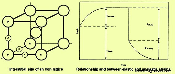
그림 1 철 격자와 탄성 및 비탄성 변형의 시간 의존성
탄성 변형률과 탄성 변형률의 조합은 인장 시험 중에 결정된 영률을 유발하며 하중 속도(또는 변형률 속도)에 따라 달라지며 주기적 또는 진동 하중을 받는 재료에서 감쇠 또는 내부 마찰을 생성할 수 있습니다. 비탄성 변형은 시험 샘플이 고정 변위에서 하중을 받고 유지될 때 인장 시험 중 응력 완화의 원인 중 하나입니다. 이 응력 완화는 종종 '탄성 후유증'이라고 하며, 원자가 선호 위치로 이동하고 탄성 변형이 발생함에 따라 고정 변위를 유지하는 데 필요한 하중이 감소하기 때문에 시간 종속 하중 강하로 인해 발생합니다. 이 탄력적인 후유증은 테스트 결과에 대한 시간 또는 로딩 속도의 중요성을 보여줍니다.
시험 샘플에 인장 하중을 가하는 데 수반되는 총 가역 변형은 탄성 및 비탄성 변형의 합입니다. 하중을 빠르게 적용하면 탄성 변형률이 0에 가까워지므로(시험 시간은 탄성 변형률에 대해 충분하지 않음) 하중 중 총 변형률은 실제 탄성 변형률과 같습니다. 동일한 하중을 매우 느리게 적용하면 탄성 변형이 하중 과정을 수반하므로 이 테스트의 총 가역 변형은 급속 하중 동안 가역 변형을 초과합니다. 저변형률 시험에서 측정된 영률은 고변형률 시험에서 측정된 것보다 낮으므로 측정된 탄성계수는 변형률에 의존합니다. Young's modulus의 낮은 값을 'relaxed modulus'라고 하고 높은 변형률에서 측정된 modulus를 'unrelaxed modulus'라고 합니다.
댐핑 용량
인장 시험 및 주기적 하중은 종종 완전히 이완된 거동에 필요한 것과 완전히 이완되지 않은 거동에 필요한 것 사이의 변형률 또는 하중 속도로 수행됩니다. 따라서 하중 또는 하중 제거 시 응력-변형률 곡선의 초기 또는 짧은 시간 부분은 이완되지 않은 거동을 생성하는 반면 곡선의 나중에 긴 시간 부분은 보다 이완된 거동을 생성합니다. 이완되지 않은 동작에서 이완된 동작으로의 전환은 응력-변형률 곡선에서 하중-하중 히스테리시스를 생성합니다. 이 히스테리시스는 로딩-언로딩 주기 동안의 에너지 손실을 나타냅니다. 에너지 손실의 양은 히스테리시스의 크기에 비례합니다. 재료 격자 내의 탄성 효과에 기인할 수 있는 이러한 에너지 손실을 '내부 마찰'이라고 합니다. 내부 마찰은 철과 강철 재료가 진동 에너지를 흡수하는 능력에 중요한 역할을 합니다. 이러한 흡수로 인해 로딩-언로딩 사이클 동안 재료의 온도가 상승할 수 있습니다. 내부 마찰에 대한 재료의 민감도를 측정하는 한 가지는 감쇠 용량입니다.
탄성과 내부 마찰은 시간과 온도에 따라 달라지므로 재료의 감쇠 용량은 온도와 변형률 속도에 따라 달라집니다. 내부 마찰과 감쇠는 진동에 대한 재료의 반응에 중요한 역할을 합니다. 로딩-언로딩 사이클 동안 상당한 내부 마찰을 일으키는 조건에서 테스트된 철 및 강철 재료는 큰 에너지 손실을 겪으며 높은 감쇠 용량을 갖는다고 합니다. 이러한 재료는 진동 흡수에 유용합니다. 예를 들면 매우 높은 감쇠 용량을 갖고 지역 진동으로부터 격리되어야 하는 기기 및 장비의 베이스에 정기적으로 사용되는 회주철이 있습니다. 밀 스탠드, 선반 및 프레스 등은 일반적으로 주철 베이스를 사용하여 바닥 및 주변 영역으로의 기계 진동 전달을 줄입니다. 그러나 높은 감쇠 용량이 항상 유용한 재료 품질은 아닙니다.
철 및 강철 재료의 비탄성, 감쇠, 응력 완화 및 탄성 계수는 재료의 미세 구조와 시험 조건에 따라 달라집니다. 이러한 특성은 일반적으로 인장 시험 기술에 의해 결정되지 않습니다. 그러나 이러한 속성과 기계 매개변수는 응력-변형률 곡선의 모양에 영향을 줍니다.
비례 제한
인장 응력-변형률 관계에서 곡률 시작을 생성하는 데 필요한 겉보기 응력은 비례 한계(PL)입니다. PL은 변형률이 응력에 방향적으로 비례하여 유지되는 최대 응력으로 정의됩니다. 비례성에서 벗어나는 것은 탄성 및/또는 소성 변형의 시작에 기인할 수 있습니다. 인장 시험 중 이러한 현상의 발생을 감지하는 능력은 응력과 변형률이 측정되는 정확도에 따라 달라집니다. PL의 측정값은 측정 정확도가 높을수록 감소합니다. PL의 측정값은 테스트 정확도에 따라 달라지므로 일반적으로 PL은 재료의 인장 특성으로 보고되지 않습니다. 또한 PL의 가치는 엔지니어링 응용 프로그램을 위한 재료의 선택, 자격 및 사용에 거의 또는 전혀 유용하지 않습니다. 훨씬 더 재현 가능하고 실용적인 스트레스는 재료의 YS입니다.
재료의 수율 및 가소성의 시작
철 및 강재의 YS는 재료가 응력과 변형률 간의 비례에서 지정된 편차를 나타내는 응력으로 정의할 수 있습니다. 비례에서 매우 작은 편차는 탄성 효과로 인해 발생할 수 있지만 선형 거동에서 이러한 편차는 완전히 가역적이며 심각한 소성(가역적) 변형 또는 항복의 시작을 나타내지 않습니다. YS의 이론적인 값은 방정식 YS =E/2p에서 계산됩니다. 여기서 E는 탄성 계수이고 p는 Pi 값(3.14159)입니다. 이론적으로 적용된 응력이 탄성 계수의 중요한 부분이 아니면 항복이 발생하지 않습니다. 일반적으로 초과 항복에 대한 이 추정치는 철 및 강철 재료의 경우 측정된 YS를 최소 150의 계수로 예측합니다. 이론적인 YS와 실제 YS 사이의 불일치는 전위의 움직임 때문입니다. 전위는 결정 격자의 결함이며 이러한 결함의 움직임은 소성 변형의 주요 메커니즘입니다. 재료의 YS를 변경하는 기술은 전위 운동의 용이성을 변경하기 위해 결함 상호작용에 의존합니다.
전위 이동성은 합금 함량, 냉간 가공 정도, 개재물 및 2상 입자의 크기, 모양 및 분포, 재료의 입자 크기에 따라 달라집니다. 합금(또는 불순물) 원자가 전위와 상호 작용하고 후속 운동을 방지하기 때문에 합금 함량이 증가함에 따라 강도가 증가합니다. 따라서 이러한 유형의 강화는 점 결함과 라인 결함의 상호 작용에서 발생합니다.
냉간 가공은 철 및 강재의 강도를 높이는 효과적인 기술입니다. 이 강화 메커니즘은 냉간 가공 비율이 증가함에 따라 재료의 전위 수가 증가하기 때문에 효과적입니다. 이러한 추가 전위는 다른 전위의 지속적인 움직임을 제한합니다. 냉간 가공은 결정 격자의 다른 라인 결함과 상호 작용하는 라인 결함으로 인한 강화의 예입니다. 압연, 스탬핑, 단조, 드로잉, 스웨이징 및 압출까지 사용하여 필요한 냉간 가공을 제공할 수 있습니다.
입자 및 위상 경계는 전위 운동도 차단합니다. 따라서 YS는 결정립계의 수가 증가하거나 구조에서 두 번째 상의 비율이 증가함에 따라 증가합니다. 결정립 크기의 감소는 단위 체적당 결정립계의 수를 증가시켜 재료 격자의 영역 결함 밀도를 증가시킵니다. 영역결함과 선결함 사이의 상호작용은 전위 이동성을 제한하기 때문에 YS는 결정립 크기가 감소하고 2차상 입자의 수가 증가할수록 증가한다.
철 및 강철 재료는 강화 메커니즘이 다르기 때문에 광범위한 YS를 나타냅니다. YS의 범위는 입자 크기, 냉간 가공 비율, 2차 입자 분포 및 기타 비교적 쉽게 정량화된 미세 구조 매개변수에 따라 달라집니다. 미세 구조 매개변수의 값은 재료의 열역학적 이력에 따라 다릅니다. 따라서 중요한 야금학적 변수에 대한 지식은 YS 데이터의 지능적인 해석과 이러한 재료로 만든 구조 및 구성요소의 설계 및 활용에 거의 필수입니다.
YS의 가장 일반적인 정의는 0.002mm/mm의 소성 변형을 일으키는 데 필요한 응력입니다. 이 변형률은 비례에서 쉽게 측정할 수 있는 편차를 나타내며 이 편차를 생성하는 데 필요한 응력은 0.2% 오프셋 YS입니다. 선형 거동에서 0.2% 편차에 도달하려면 상당한 양의 전위 운동이 필요합니다. 따라서 표준 인장 시험 동안 0.2% 오프셋 항복 강도는 시험기 변수, 그립 효과 및 탄성과 같은 가역적 비선형 변형과 거의 무관합니다. 이러한 독립성으로 인해 0.2% 오프셋 항복강도는 철 및 강재의 기계적 특성 설명에 사용되는 재현 가능한 특성입니다. 그러나 YS의 크기 또는 기타 인장 특성은 테스트된 재료의 결함 구조에 따라 달라진다는 것을 아는 것이 중요합니다. 따라서 YS를 의미 있는 설계 매개변수로 사용하려면 재료의 열역학적 이력을 알아야 합니다.
항복점
일부 철 및 강철 재료, 주로 실온에서 시험된 저탄소강에서 전위 운동의 시작은 상대적으로 점진적인 과정이 아니라 갑작스러운 과정입니다. 이러한 급격한 항복의 발생은 0.2% 오프셋 방법에 의한 항복의 표현을 비실용적으로 만든다. 급격한 항복으로 인해 연강의 응력-변형률 곡선은 항복점(YP)을 가지며 연강의 YS는 더 낮은 항복 응력으로 설명됩니다. YP는 용질(용해된) 원자와 용매(호스트) 격자의 전위의 상호 작용으로 인해 발생합니다. 연강에서 용질-전위 상호작용은 C 이동 및 전위와의 상호작용을 포함합니다. 이 상호작용으로 인해 전위 부근에서 용질의 농도가 높아지므로 C가 전위로 편석되어 YP점이 발생한다고 합니다.
전위 주변의 많은 틈새 사이트가 확대되어 용질 원자가 점유하기 위해 에너지가 낮거나 선호되는 사이트입니다. 이러한 확대된 부위가 점유되면 높은 농도의 용질 또는 대기가 전위와 관련됩니다. 연강에서 용질 편석은 전위에서 C가 풍부한 분위기를 생성합니다. 이러한 운동은 C 분위기로부터 전위의 분리가 필요하기 때문에 전위의 운동이 제한된다. 분리가 일어나자 마자 지속적인 전위 운동에 필요한 응력이 감소하고 인장 시험에서 더 낮은 YS에 도달합니다. 이 항복 과정에는 테스트 샘플의 국부적인 영역에서 전위 운동이 포함됩니다. 전위 운동은 소성 변형이므로 전위가 이동한 영역은 재료의 변형 영역 또는 밴드를 나타냅니다. 이러한 국부적으로 변형된 밴드를 Lu¨ders 밴드라고 합니다. 일단 시작되면 추가 변형으로 인해 Lu¨ders 밴드가 테스트 샘플의 게이지 길이 전체에 전파됩니다.
이 전파는 강의 낮은 YS인 일정한 응력에서 발생합니다. 전체 게이지 섹션이 항복하면 전위와 다른 전위의 상호 작용으로 인해 응력-변형률 곡선이 상승하기 시작하고 변형 경화가 시작됩니다. YP 및 Lu¨der band의 존재는 급격한 연화 및 국부적인 변형이 가공 기술에 미치는 영향 때문에 중요합니다. 예를 들어, 갑작스러운 국부적 항복은 재료의 급격한 흐름을 유발합니다. 연신 장비에 가해지는 부하가 급격하게 변하고 처리 장비에 의해 흡수되어야 하는 에너지의 큰 방출을 유발하기 때문에 연신 작업에서 재료 흐름이 흐트러지는 것은 바람직하지 않습니다. 또한 국부적인 Lu¨der 변형은 스탬핑 과정에서 재료에 스트레치 마크를 생성합니다. 이러한 스트레치 마크를 '스트레처 변형'이라고 하며 스탬핑된 표면에서 쉽게 볼 수 있습니다. 이것은 표면의 외관을 악화시키고 구성 요소의 유용성을 감소시킵니다. YP가 없는 재료에 스탬프를 찍으면 변형경화 과정이 재료 전체에 균일하게 변형을 퍼뜨리기 때문에 매끄러운 표면이 나타납니다.
수율에 대한 입자 크기의 영향
구조용으로 사용되는 철 및 강철 재료는 다결정질입니다. 이러한 물질은 일반적으로 많은 수의 미세한 결정 또는 입자를 포함합니다. 알갱이의 3차원 형상이 상당히 복잡하기 때문에 알갱이의 크기를 정확하게 정의하기가 어렵습니다. 입자가 구형인 경우 입자 직경(d)을 사용하여 크기를 지정할 수 있습니다. 결정립 크기를 보다 정확하게 지정하기 위해 일반적으로 평균 결정립 절편(I)과 결정립 체적에 대한 입계면의 비율(Sv)을 포함합니다. 이 두 매개변수는 정량적 금속학 기술을 통해 설정할 수 있습니다.
그러나 역사적 이유로 매개변수 d는 철 및 강철 재료의 YS에 대한 입자 크기의 영향을 설명하는 데 사용되는 가장 일반적인 측정입니다. 이 영향은 종종 경험적 방정식을 통해 YS가 입자 크기와 관련되는 Hall-Petch 관계를 통해 정량화됩니다.
결정립 경계는 전위 운동의 장벽으로 작용하여 전위가 경계 뒤에 쌓이게 합니다. 이러한 전위의 축적은 축적의 선단에 응력을 집중시키고 응력이 충분할 때 인접한 Grain에 추가적인 전위가 핵을 생성할 수 있다. 전위 더미의 끝에서 응력의 크기는 더미의 전위 수에 따라 달라집니다. 파일업에 포함된 전위의 수는 큰 입자 부피로 인해 입자 크기가 증가함에 따라 증가합니다. 쌓이는 전위 수의 이러한 차이는 비슷한 순도의 미세 입자 재료보다 큰 입자 재료에서 새로운 전위가 핵 생성되기 더 쉽게 하며 전위 핵 생성 용이성의 이러한 차이는 YS의 차이에 직접 외삽됩니다. .
냉간 가공 및 변형 경화 효과
철 및 강재의 재결정 온도보다 높은 온도에서의 소성 변형은 열간 가공이고, 이들 재료의 재결정 온도보다 낮은 온도에서의 소성 변형은 냉간 가공입니다. 재결정 온도 이상의 인장 시험 동안 이러한 재료는 상당한 변형 경화를 나타내지 않으며 인장 YS는 재료가 효과적으로 지지할 수 있는 최대 응력이 됩니다. 이러한 재료에 대한 응력-변형률 곡선은 인장 변형률이 증가함에 따라 지속적인 소성 변형을 유발하는 데 필요한 응력이 증가함을 보여줍니다.
지속적인 변형에 필요한 응력은 종종 특정 인장 변형률에서의 유동 응력으로 지정됩니다. 변형률이 증가함에 따라 증가하는 유동 응력은 냉간 가공에 의해 재료의 강도를 증가시키는 기초입니다. 재료의 강도에 대한 입자 크기의 영향은 냉간 가공 공정 전반에 걸쳐 유지됩니다. 강도의 결정립 크기 의존성이 변형 경화 공정 전반에 걸쳐 유지된다는 사실은 이러한 재료의 다양한 강화 메커니즘 간의 상호 작용 가능성을 설정합니다. 예를 들어 냉간 가공은 점결함과 전위 사이의 상호작용을 통해 강도를 증가시키며 이러한 효과는 합금의 효과에 가산됩니다.
또한 강도는 냉간 가공 공정의 영향을 받는 유일한 인장 특성이 아닙니다. 냉간 가공이 증가함에 따라 연성이 감소하며, 냉간 가공이 너무 광범위하면 냉간 가공 중에 철근이 균열 및 파단될 수 있습니다. 강도와 연성에 대한 냉간 가공의 전반적인 영향은 강도의 증가와 연성의 감소로 인해 응력-변형률 곡선 아래의 면적이 감소한다는 것입니다. 이것은 이 영역이 철근을 파단하는 데 필요한 일 또는 에너지를 나타내기 때문에 중요하며 인장 시험 결과 냉간 가공 비율이 증가함에 따라 이 에너지가 감소함을 보여줍니다.
압연, 드로잉, 스탬핑 또는 단조에 의한 냉간 가공은 미세 구조를 변경합니다. 결과 입자 모양은 처리 중 금속 흐름의 방향에 따라 결정됩니다. 냉간 압연된 시료의 입자는 길어지고 평평해지며 반구형 입자에서 팬케이크 모양의 입자로 변합니다. 막대 드로잉 공정은 바늘 모양의 곡물을 생산합니다. 곡물 모양의 변화와 더불어 냉간 가공으로 곡물 내부가 뒤틀립니다. 전위 밀도가 높은 밴드(변형 밴드)가 발생하고 쌍경계가 휘고 결정립계가 거칠고 왜곡됩니다. 변형으로 인한 미세조직의 변화는 이방성이므로 단강재의 인장 특성은 종종 이방성입니다. 냉간 가공으로 인한 변형 경화 미세 구조 및 수반되는 기계적 특성은 어닐링에 의해 크게 변경될 수 있습니다. 더 높은 온도로 가열함으로써 발생하는 미세구조적 변화는 어닐링의 시간과 온도에 따라 달라집니다. 이 온도 의존성은 어닐링이 효과적이려면 원자 운동이 필요하기 때문에 발생합니다.
인장 강도
변형 경화 능력은 철과 강철 재료를 다른 엔지니어링 재료와 분리하는 기계적 거동의 일반적인 특성 중 하나입니다. 모든 금속 재료가 이러한 특성을 나타내는 것은 아닙니다. 예를 들어, 크롬(Cr)은 변형 경화의 증거 없이 인장 시험에서 매우 부서지기 쉽고 파괴됩니다. 취성 재료에 대한 응력-변형률 곡선은 세라믹 재료의 응력-변형률 곡선과 유사합니다. 상당한 소성 변형이 일어나기 전에 균열이 발생합니다. 이러한 취성 재료는 실제 YS가 없으며 파괴 응력은 재료가 지원할 수 있는 최대 응력입니다. 그러나 철 및 강철 재료는 파단 전에 소성 변형을 일으키며 재료가 지지할 수 있는 최대 응력은 YS보다 상당히 높습니다. 이 최대 응력(원래 치수 기준)은 재료의 극한 또는 인장 강도(TS)입니다.
YS와 TS 사이의 여유는 구조물의 철 및 강철 재료에 대한 작동 안전 계수를 제공합니다. 이 안전마진 외에 TS의 실제 가치는 실용화가 거의 없다. 복잡한 사용 하중을 견디는 구조의 능력은 TS와 거의 관련이 없으며 구조 설계는 항복을 기반으로 합니다. TS는 측정하기 쉽고 응력-변형률 곡선의 최대 응력이기 때문에 자주 보고됩니다. 엔지니어링 코드는 때때로 재료가 특정 TS 요구 사항을 충족하도록 지정합니다.
역사적으로, TS는 항복을 피하기 위해 경험 기반 감소를 사용하여 설계 계산에 사용되었습니다. 응력-변형률 곡선 측정의 정확도가 향상됨에 따라 TS의 활용도가 감소했으며 1940년대에는 여러 설계 코드가 항복을 기반으로 했습니다. TS와 경도, 피로 강도(FS), 응력 파열 및 기계적 특성을 연관시키는 대규모 경험적 데이터베이스가 있습니다. 이러한 상관 관계, 역사적 코드 요구 사항 및 취성 재료를 포함하는 구조 설계가 TS를 기반으로 한다는 사실은 TS를 설계 기준으로 계속 사용하기 위한 기술적 기반을 제공합니다.
철강 재료의 냉간 가공 및 기타 강화 메커니즘은 YS를 증가시키는 것만큼 TS를 빠르게 증가시키지 않습니다. 따라서 강화 공정은 종종 소성 변형을 받는 능력의 감소를 동반합니다. 이러한 감소는 파괴 이전에 에너지를 흡수하는 재료의 능력을 감소시키며 많은 경우에 이러한 재료의 성공적인 활용에 중요합니다. 이러한 재료의 인장 거동을 분석하면 재료의 에너지 흡수 능력에 대한 통찰력을 얻을 수 있습니다.
인성
파손 없이 에너지를 흡수하는 능력은 재료의 인성 때문입니다. 대부분의 경우 철 및 강재의 파단은 기존 결함에서 시작됩니다. 이러한 결함은 미세 구조의 요소가 될 만큼 충분히 작을 수 있으며, 약간 더 크면 재료의 거시적 균열 또는 극단적인 경우 구조에서 시각적으로 관찰 가능한 불연속성이 될 수 있습니다. 강인한 강재는 항복 및 소성 변형과 같은 공정을 통해 결함이 전파되는 것을 방지합니다. 이 변형의 최대값은 결함의 끝 부분 근처에서 발생합니다. 파괴는 인장 응력과 소성 변형 또는 변형을 모두 포함하기 때문에 응력-변형 곡선을 사용하여 재료 인성을 추정할 수 있습니다. 그러나 재료 인성을 측정하도록 설계된 특정 테스트가 있습니다. 이러한 테스트의 대부분은 사전 균열된 샘플로 수행되며 충격 및 파괴 역학을 모두 포함합니다. 인장 거동을 기반으로 한 인성 계산은 추정치이며 설계에 사용되지 않습니다.
응력-변형률 곡선 아래의 면적은 인장 시험 중 재료에 의해 흡수된 에너지의 척도입니다. 이 영역은 재료의 인성에 대한 대략적인 추정치입니다. Since the plastic strain associated with tensile deformation of iron and steel materials is typically several orders of magnitude greater than the accompanying elastic strain, plasticity or dislocation motion is very important to the development of toughness. This is demonstrated by the stress-strain curves for a brittle, a semi-brittle, and a ductile material. Brittle fracture takes place with little or no plastic strain, and thus the area (A) under the stress-strain curve is given by the equation A =0.5 Se. Estimation of the fracture energy from the typical tensile properties of mild steel test sample with a YS of 205 MPa, TS of 415 MPa, and strain to fracture value of 0.3, gives 1.12 J/ cu mm of gauge section of the test sample.
The ratio of the energy for ductile fracture to the energy for brittle fracture is 900. This ratio increases with increasing strain to fracture and with increasing strain hardening. The area and energy relationship is only approximate. The utility of such toughness estimates is the ease with which testing can be done and the insight that the estimates provide into the importance of plasticity to the prevention of fracture. Further, a plastic strain of only 0.01 % can have a remarkable effect on the ability of the material to absorb energy without fracturing.
Toughness is a very important property for many structural applications. Crane arms, ship hulls, axles, gears, and couplings are all required to absorb energy during service. The ability to withstand earthquake loadings, system overpressures, and even minor accidents also need material toughness. Increasing the strength of iron and steel materials usually reduces ductility and, in many cases, reduces toughness. Thus, increasing the strength of the material can increase the likelihood of service-induced failure when material toughness is important for satisfactory service.
This is seen by comparing the areas under the two stress-strain curves in Fig 2. The cross-hatched areas in Fig 2 show another tensile property which is the modulus of resilience. Modulus of resilience can be measured from tensile stress-strain curves. The ability of iron and steel materials to absorb energy through elastic process is the resilience of the material. The modulus of resilience is defined as the area under the elastic portion of the stress-strain curve. Increasing the YS and/or decreasing Young’s modulus increase the modulus of resilience and improve the ability of these materials to absorb energy without undergoing permanent deformation.
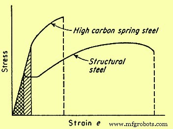
Fig 2 Comparison of the stress-strain curves for high and low toughness steels
Material ductility
Material ductility during tensile testing is generally established by measuring either the elongation to fracture or the reduction in area (RA) at fracture. In general, measurement of ductility is of interest in three ways namely (i) to indicate the extent to which a steel can be deformed without fracture in metalworking operations such as rolling, forming, or extrusion, (ii) to indicate to the designer, in a general way, the ability of the steel to flow plastically before fracture, and (iii) to serve as an indicator of changes in impurity level or processing conditions. Ductility measurement is to be specified to assess material quality even though no direct relationship exists between the ductility measurement and the performance.
Tensile ductility is a very useful measure during the assessment of material quality. Many codes and standards specify minimum values for tensile ductility. One reason for these specifications is the assurance of adequate toughness without the necessity of requiring a more costly toughness specification. Most changes in material composition and/or processing conditions produce changes in tensile ductility. Further, the metal-working features of iron and steel materials are better correlated with the ability to strain harden than with the ductility of the material. The strain-hardening abilities of many iron and steel materials used for engineering service have been quantified through the analysis of true stress-strain behaviour.
True stress-strain relationship
Conversion of engineering stress-strain behaviour to true stress-strain relationship shows that the maximum in the engineering stress-strain curve results from tensile instability, not from a decrease in the strength of the material. The drop in the engineering stress-strain curve is artificial and occurs only because stress calculation is based on the original cross-sectional area. Both testing and analysis show that, for most iron and steel materials, the tensile instability corresponds to the onset of necking in the test specimen. Necking results from strain localization. Hence, once necking is initiated, true strain cannot be calculated from sample elongation. Due to these and other analytical limitations of engineering stress-strain data, if tensile data is used to understand and predict metallurgical response during the deformation associated with fabrication processes, then true stress-true strain relationship is favoured.
The deformation which can be accommodated without fracture in a deep drawing operation varies with the material. As an example, austenitic stainless steel can be successfully drawn to 50 % RA whereas ferritic steel may fail after around 20 % to 30 % RA in similar drawing operations. Both types of steels undergo in excess of 50 % RA during tensile testing. This difference in drawability correlates with the strain-hardening exponent (n) and therefore is apparent from the slope of the true stress-strain curves for the two steels.
The n values for ferritic and austenitic steels are typically 0.25 and 0.5 respectively. A perfectly plastic material has a n value of zero and a completely elastic solid has a n value of one. Most iron and steel materials have n values between 0.1 and 0.5. Strain-hardening exponents correlate with the ability of dislocations to move around or over dislocations and other obstacles in their path. Such movement is termed ‘cross slip’. When cross slip is easy, dislocations do not pile up behind each other and n value is low. Mild steel is the example which undergoes cross slip easily. The n value increases as cross slip becomes more difficult. Cross slip is very difficult in austenitic stainless steel and the n value for this steel is around 0.5.
Tensile samples, sheets, plates, wires, rods, and other metallic sections have spot-to-spot variations in section size, YS, and other microstructural and structural in-homogeneities. Plastic deformation of these materials initiates at the locally weak regions. In the absence of strain hardening, this initial plastic strain reduces the net section size and focuses continued deformation in the weak areas. However, strain hardening causes the flow stress in the deformed region to increase. This increase in flow stress increases the load necessary for continued plastic deformation in the area and causes the deformation to spread throughout the section. The higher the n value, the greater is the increase in low stress and the greater is the tendency for plastic deformation to become uniform. This tendency has a major impact on the fabricability of the iron and steel materials.
As an example, the maximum RA which can be accommodated in a drawing operation is equal to the n value as determined from the true stress-strain behaviour of the material. Because of such correlation, the effect of process variables such as strain rate and temperature can be evaluated through tensile testing. This provides a basis to estimate the effect of process variables without direct, in-process assessment of the variables.
Temperature and strain rate effects
The YS of most iron and steel materials increases as the strain rate increases and decreases as the temperature increases. This dependence results from a combination of several metallurgical factors. As an example, dislocations are actually displacements and hence cannot move faster than the speed of sound. Also, as dislocation velocities approach the speed of sound, cross slip becomes increasingly difficult and the n value increases. This increase in the n value increases the flow stress at any given strain, thus increasing the YS of the material. A decrease in ductility and even a transition from ductile to brittle fracture can also be associated with strain rate induced increases in the YS.
In many respects, decreasing the temperature is similar to increasing the strain rate. The mobility of dislocations decreases as the temperature decreases, and hence for most of the iron and steel materials, the strength increases and the ductility decreases as the temperatures are lowered. If the reduction in dislocation mobility is adequate, the ductility can be reduced to the point of brittle fracture. Iron and steel materials which show a transition from ductile to brittle fracture when the temperature is lowered are not to be used for structural application at temperature which is below this transition temperature.
Dislocation motion is inhibited by interaction between dislocation and by the alloying or impurity (alien) atom. The effect of this interaction is both time and temperature dependent. The interaction acts to increase the YS and limit ductility. The process is most effective when there is enough time for alien atom to segregate to the dislocation and when dislocation velocity is almost equal to the diffusion velocity of the alien atom. Hence, at any given temperature, dislocation- alien atom interaction is at a maximum at some intermediate strain rate. At low strain rate, the alien atom can diffuse as rapidly as the dislocation moves and there is little or no tendency for the deformation process to force a separation of dislocation from its solute atmosphere. At high strain rates, once separation has been achieved, there is no adequate time available for the atmosphere to be re-established during the testing period. Atom movement increases with increasing temperature, thus the strain rate which allows dislocation-alien atom interaction to occur is temperature dependent. Since this interaction limits ductility, the elongation in tensile testing can show a minimum at intermediate test temperature where such interaction is very effective.
The effect of time dependent dislocation-alien atom interaction on the stress-strain curve of iron and steel materials is termed as ‘strain aging’ and ‘dynamic strain aging’. Strain aging is usually apparent when tensile testing of the material which shows a sharp YP, is interrupted. If the testing sample is unloaded after being strained past the YP, through the Lu¨ders strain region and into the strain-hardening portion of the stress-strain curve, either of two behaviours are observed when the tensile test is resumed.
If the sample is reloaded in a short period of time, the elastic portion of the reloading curve is parallel to the original elastic loading curve and plastic deformation resumes at the stress level which was reached just before the testing was interrupted. However, if the time between unloading and reloading is enough for segregation of alien atom to the dislocation, the YP reappears and plastic strain is not reinitiated when the unloading stress level is reached. This reappearance of the YP is strain aging, and the strength of the strain aging peak is dependent on both time and temperature since solute-atom diffusion and segregation to dislocation is needed for the peak to develop. If tensile strain rate is in a range where solute segregation can occur during the testing, dynamic strain aging is observed. Segregation pins the previously mobile dislocation and increases the flow stress, and when the new, higher flow stress is reached the dislocation is separated from the solute atmosphere and the flow stress decreases. This alternate increase and decrease in flow stress causes the stress-strain curve to be serrated.
Serrated flow is usual in mild steel since it contains mobile, alloy or impurity element. This effect has been initially studied in detail by Portevin and LeChatelier and is often called the Portevin-LeChatelier effect. Processing condition is to be selected to avoid strain aging effect. This selection essentially involves the control of processing strain rate and temperature.
Special testing methods
The tensile test provides basic information concerning the response of iron and steel materials to mechanical loading. Testing temperature and strain rate (or loading rate) normally is controlled due to the effects of these variables on the metallurgical response of the sample. The tensile testing usually measures strength and ductility. These parameters are frequently sensitive to the sample configuration, testing environment, and the manner in which the testing is conducted. Special tensile testing methods have been developed to measure the effect of testing/sample conditions on the strength and ductility of iron and steel materials. These testing methods include the notch tensile test and the slow-strain-rate tensile test.
Notch tensile testing
Iron and steel materials used in engineering applications is often required to withstand multi-axial loading and high stress concentration because of component configuration. Standard tensile testing measures material performance in a smooth bar sample exposed to uniaxial load. This difference between application and testing sample can reduce the ability of the standard tensile testing to predict material response under anticipated condition of application. Also, the reduction in ductility usually induced by multi-axial loading and stress concentration may not be visible in the testing result. The notched tensile testing therefore has been developed to minimize this weakness in the standard tensile testing and to examine the behaviour of material in the presence of flaws, notches, and stress concentrations.
The notched tensile sample usually contains a 60 deg notch which has a root radius of less than 0.025 mm. The stress state just below the notch tip approaches tri-axial tension, and for ductile steels this stress state normally increases the YS and decreases the ductility. This increase in YS results from the effect of stress state on dislocation dynamics. Shear stress is needed for the dislocation motion. Pure tri-axial loading does not produce any shear stress. Hence, dislocation motion at the notch tip is limited and the YS value is increased. This constraint in dislocation motion also reduces the ductility of the notched sample. For low ductility steels, the notch-induced reduction in ductility can be so severe that failure takes place before the 0.2 % offset YS is reached.
The sensitivity of iron and steel materials to notch effect is termed as the ‘notch sensitivity’. This sensitivity is quantified through the ratio of notch strength to smooth bar TS. Material which is notch sensitive has ratio less than one. Smooth bar tensile data for these materials does not satisfactory predicts the material behaviour under service conditions. Tough ductile material often is notch-strengthened and has notch sensitivity ratio greater than one, thus the standard tensile testing is a conservative predictor of performance for this material.
Slow strain rate testing
Testing environments can also have adverse effects on the tensile behaviour of iron and steel materials. The characterization of environmental effect on material response can be accomplished by conducting the tensile testing in the environment of interest. Since the severity of environmental attack usually increases with increasing time, tensile testing designed to determine environmental effects often is conducted at very low strain rate. The low strain rate increases the testing time and maximizes exposure to the testing environment. This type of testing is termed either ‘slow strain rate testing’ (SSRT) or ‘constant extension rate testing’ (CERT). Exposure to the aggressive environment can reduce the strength and/or ductility of the testing sample. This reduction can be accompanied by the onset of surface cracking and/or a change in the fracture mode. SSRT or CERT study which displays harmful effects on the tensile behaviour, establishes that the test material is susceptible to environmental degradation.
This susceptibility can cause concern over the utilization of the material in that environment. Conversely, the test can show that the tensile behaviour of the material is not influenced by the environment and is therefore suitable for application in that environment. SSRT or CERT can be used to screen materials for potential service exposures and/or examine the effects of anticipated operational changes on the materials used in process systems. In either case, the intent is to avoid materials utilization under conditions which may degrade the strength and ductility and cause premature failure. In addition to the tensile data, evidence of adverse environmental effect can also be found through examination of the fracture morphology of the testing samples of CERT and SSRT.
Fracture characteristics
Tensile fracture of ductile iron and steel materials generally initiates internally in the necked portion of the tensile bar. Particles such as inclusion, dispersed second phase, and/or precipitate can serve as the nucleation sites. The fracture process begins by the development of small hole, or micro-void, at the particle-matrix interface. Continued deformation enlarges the micro-void until, at some point in the testing process, the micro-void contacts other micro-void and coalesces. This process is termed ‘micro-void coalescence’ and gives rise to the dimpled fracture surface topography characteristic of the ductile failure processes.
The surface topography of a brittle fracture differs significantly from that of micro-void coalescence. Brittle fracture generally initiates at imperfections on the external surface of the material and propagates either by trans-granular cleavage like process or by separation along grain boundary. The resultant surface topography is either faceted, perhaps with the river like pattern typical of cleavage, or inter- granular, producing a ‘rock candy’ like appearance. The testing material can be inherently brittle or brittleness can be introduced by heat treatment, lowering of the testing temperature, the presence of an aggressive environment, and/or the presence of a sharp notch on the testing sample.
The temperature, strain rate, test environment, and other conditions, including sample surface finish for tensile testing, are generally well established. An understanding of the effects of such testing parameters on the fracture characteristics of the test sample can be very useful in the determination of the susceptibility of iron and steel materials for degradation during the fabrication or during the application. Typically, any heat treatment or testing condition which causes the fracture process to change from micro-void coalescence to a more brittle fracture mode reduces the ductility and toughness of the material and can promote early fracture under selected service conditions. Since the fracture process is very sensitive to both the metallurgical condition of the sample and the conditions of the tensile testing, characterization of the fracture surface is an important component of many tensile-testing programs.
제조공정
주물 디자인을 위한 금속 특성 및 구성 녹을 수 있는 모든 고체 금속을 주조할 수 있습니다. 주조 공장은 이러한 주조 작업을 수행하는 공장으로, 소수의 금속과 방법으로 전문 지식을 개발하고 생산 가치와 효율성을 극대화하기 위해 표준 제품을 설계합니다. 금속과 주조 방법은 서로 영향을 미칩니다. 제품에 대한 최상의 주조 선택은 금속이 용융, 냉각 및 고체 상태에서 어떻게 거동하는지에 의해 영향을 받습니다. 이러한 종속성의 경우 파운드리의 전문 분야는 그들이 만드는 제품의 종류를 결정하는 일부입니다. 다이캐스트 어린이 장난감을
주철과 주강의 차이점은 무엇입니까? 주물은 설계 세부 사항을 위한 탁월한 능력을 제공하므로 종종 추가 제작 및 조립이 필요하지 않습니다. 여러 유형의 금속 및 합성물을 포함하여 많은 재료를 주조할 수 있지만 특히 철과 강철은 광범위한 응용 분야에서 우수한 기계적 특성을 보입니다. 주철과 강철은 표면적으로 유사하게 보일 수 있지만 생산에서 적용까지 각각 뚜렷한 장점과 단점이 있습니다. 이러한 장점과 단점을 이해하고 적절하게 선택하는 것은 용서할 수 없는 강도와 내구성과 금세 광택을 잃는 파손되거나 변형된 부품의 차이를 의미할