

제조공정

산업 제조
연도 가스 정화 기술 및 시스템
환경 오염은 현재 전 세계적으로 가장 큰 문제 중 하나입니다. 일련의 지구 환경 문제로 인해 점점 더 많은 사람들이 환경과 자원이 인간의 생존과 발전을 위한 기본 필수품임을 깨닫게 되었습니다. 대부분의 기술 공정의 산물인 배가스는 다양한 고체 입자로 오염되어 있습니다. 가스(발열량이 충분한 경우)를 더 사용하거나 대기 중으로 방출하려면 가스를 청소해야 합니다. 그러나 대기 배출 제어에는 비용이 많이 들고 운영 조직에 대한 재정적 보상은 거의 없습니다.
지난 몇 년 동안 여러 국가에서 배출 제어 분야의 태도, 교육, 책임 및 규정이 완전히 변경되었습니다. 대기오염의 폐해로부터 미래세대를 살리기 위해 배출가스 규제는 시간이 지날수록 더욱 엄격해지고 있습니다. 이제 여러 조직이 대기 오염에 대한 태도를 빠르게 바꾸고 오염 통제 활동에 적극적으로 참여하고 있습니다. 이제 조직은 대중에게 '깨끗한' 제품을 생산하는 책임 있는 조직으로 보이기를 원합니다. 시장이 점점 더 '깨끗한' 제품을 요구함에 따라 이는 부분적으로 시장 주도적입니다. 오늘날과 같은 상황에 처한 고객들은 환경에 대한 책임과 깨끗한 환경의 이점에 대해 더욱 교육을 받고 있습니다.
연도 가스 청소 시스템의 목적은 환경과 건강에 유해한 물질의 대기 배출을 줄이는 것입니다. 여기에는 예를 들어 산성화 및 부영양화를 일으키는 중금속, 다이옥신 및 물질. 연도 가스의 일부 물질은 독성 및 발암성이므로 배출을 줄이는 것이 중요합니다. 산림과 호수의 산성화는 연도 가스에서 황과 질소 산화물을 제거함으로써 상당히 감소되었습니다.
야금, 화학 및 화력 발전소의 기술 프로세스는 일반적으로 고온에서 먼지가 많은 폐연도 가스를 생성합니다. 이러한 가스의 구성과 양은 기술 프로세스 및 원료의 특성에 따라 다릅니다. 폐연도 가스의 배출은 실제로 사용된 원료와 이러한 공장에서 일어나는 공정 및 반응의 결과입니다. 연도 가스에는 이산화탄소, 일산화탄소, 황 산화물(SO2 및 SO3) 및 질소(NOx), 수소, 황화수소(H2S), 불소(HF 형태), 염소(HCl 형태)가 포함될 수 있습니다. ), 비소, 수은, 휘발성 유기 화합물(VOC), 수증기, 먼지 등. 수증기는 무해하지만 굴뚝 배출구에서 눈에 보이는 연기 기둥에 기여합니다.
고온에서 발생하는 몇 가지 기술 프로세스가 있습니다. 또한 이러한 공정 중 상당수는 원료를 처리하며 그 중 일부는 벌금 형태입니다. 따라서 이러한 모든 공정은 대기 중으로 오염 가스와 입자상 물질을 방출하기 쉽습니다. 이것은 차례로 식물 주변의 공기 품질에 영향을 미칩니다. 공기의 질을 개선하고 보호하기 위해 다양한 오염 제어 장치가 배출 감소에 사용됩니다. 수년 전부터 오염 제어 장비는 오염 물질의 양이 매우 많거나 본질적으로 유독한 공정에만 사용되었습니다. 이 장비는 또한 회복 가치가 있는 곳에서 더 일찍 사용되었습니다. 그러나 현재의 시나리오에서는 환경 규제가 점점 더 엄격해지고 환경에 대한 사회의 관심이 높아짐에 따라 모든 기술 프로세스의 배출을 조사하고 모든 영역에 장비를 설치하여 배출을 줄이는 것이 필요하게 되었습니다. 가능한 최소 수준으로 배출합니다.
일반적으로 기술 프로세스에 기인하는 대기 오염원의 주요 그룹이 5개 이상 있으며, 각각은 저감을 위한 특정 모범 사례 기술이 있습니다. 이러한 그룹화는 강한 산성 가스 농도가 발생하기 때문에 포괄적인 목록을 구성하지 않습니다. 황산 공장과 같은 대체 연도 가스 정화 기술이 구현되어야 합니다. 가스 청소 기술에 대한 이러한 5가지 주요 그룹은 (i) 먼지 및 미립자 배출 제어, (ii) SO2/HCl 및 HF 제어와 같은 산성 가스, (iii) NOx 저감 제어, (iv) 산성 안개 및 기타 에어로졸과 관련됩니다. 통제, (v) 수은, 다이옥신/퓨란 및 VOC 통제. 산성 가스 고정 기술의 경우 항상 그렇듯이 제품 폐기가 과제로 남아 있습니다. 대부분의 응용 분야에서 폐기물은 그에 수반되는 필요한 운영 비용으로 간단히 매립됩니다. 이 5개 그룹의 가스 정화 기술에 대한 배출 제어 장비는 기본적으로 (i) 먼지 및 미립자 배출 제어 장비와 (ii) 가스 배출 제어 장비의 두 가지 유형입니다. 이 기사는 먼지 및 미립자 배출 제어 시스템에 중점을 둡니다.
일반적으로 고온 가스 세정의 문제는 아마도 업계에서 가장 당혹스러운 문제일 것입니다. 문제는 일반적으로 700°C에서 1,500°C 범위의 온도에서 기체에 분산된 극도로 미세한 입자와 관련이 있기 때문에 어렵습니다. 어떤 경우에는 훨씬 더 높은 온도가 포함될 수 있습니다. 미세한 에어로졸과 높은 온도로 인해 일반적인 접근 방식으로는 일반적으로 문제가 해결되지 않습니다. 따라서 이 분야의 발전은 그다지 빠르지 않습니다. 고온 가스 세정과 관련된 기본적인 문제는 경제성과 세정에 대한 근본적인 요구 사항입니다.
어떤 경우에는 폐가스의 청소가 필요합니다. 왜냐하면 그것이 상당한 가치가 있는 물질을 나타내기 때문입니다. 또는 입자상 물질이 제거되면 가스가 남아 가연성이며 열이나 에너지의 형태로 회수되어 작업에 사용할 수 있습니다. 프로세스. 다른 경우에는 미립자, 기체 또는 일반적인 조합의 폐수의 경제적 가치가 너무 작아서 폐기 비용이 상당한 문제를 나타냅니다. 이러한 경우 대기 오염을 방지하기 위해 필요한 청소 또는 제거는 무형의 수익만 있는 것입니다.
두 번째 범주에서 업계의 바람은 증가된 생산 비용의 형태로 부담을 가하지 않고 최소한의 비용으로 청소를 얻는 것입니다. 지역 사회의 대기 오염과 재산 또는 대중에 대한 가능한 부상을 방지하는 비용은 일반적으로 좋은 홍보 외에는 가시적인 회복이 없습니다.
이러한 가스의 효과적인 세척은 다양한 불순물로 인해 심각한 기술적 문제를 나타냅니다. 고효율 가스 세정 시스템은 고온 야금 및 화력 발전소의 안정적인 작동과 긴 캠페인 수명에 필수적이며 운영자가 관련 오염 제어 표준을 충족할 수 있도록 합니다. 가스 냉각 및 세척 설비의 선택은 기술적 타당성, 경제적 수용성 및 환경적 적합성과 관련하여 매우 중요합니다. 또한, 가스 청소 시스템은 최상의 환경 보호를 제공하는 동시에 최고 수준의 청소 효율성, 안전성 및 신뢰성으로 설계되어야 합니다.
가스 세정 시스템 설계의 중요한 기준은 (i) 시간당 N cum 단위의 가스 부피, (ii) 가스의 화학적 조성, (iii) 가스의 수분 함량, (iv) 가스의 온도, (v)입니다. ) 가스의 분진 함량(kg/h), (vi) 부식성, 연마제 등과 같은 분진의 특성, (vii) 분진의 입자 크기 범위, (viii) 배출 기준, (ix) 가스의 폭발 특성 , (x) 위생적인 디자인, (xi) 온라인 또는 오프라인 시스템, (xii) 건축 자재
가스 세정 시스템의 설계에는 세 가지 주요 고려 사항이 있습니다. 첫 번째는 배출되는 먼지와 가스를 포착하고 연기로 가득 찬 작업 영역을 방지하도록 설계된 후드입니다. 두 번째는 후드에 갇힌 가스와 먼지가 대기로 방출되기 전에 청소되어야 한다는 것입니다. 세 번째는 포집된 먼지가 공기나 하천에 다시 혼입되어 다시 공해 문제가 되지 않도록 처리해야 한다는 것입니다.
야금로에서 나오는 연도 가스는 고온(700 ~ 1,500 ℃ 또는 그 이상)과 먼지 함량이 높은 경우가 많습니다. 따라서 가스 세정 시스템에서 이러한 가스를 처리하기 전에 이러한 가스를 400℃ 미만의 온도로 냉각해야 합니다. 실제로 여러 가스 냉각 방법이 사용됩니다. (i) 폐열 보일러, (ii) 공기를 이용한 간접 냉각, (iii) 물로 간접 냉각, (iv) 물을 사용한 증발 냉각입니다.
폐열 보일러는 주로 연속 가스 유량으로 연도 가스를 생성하는 기술 공정에서 연도 가스를 냉각하는 데 사용됩니다. 이를 통해 폐열보일러를 이용한 가스냉각을 적용하여 좋은 운영결과를 얻을 수 있습니다.
공기를 이용한 간접 냉각으로 가스를 냉각하는 시스템은 (i) 냉각 공기가 공정 가스의 이슬점보다 온도가 낮고 산의 응축이 표면에서 발생하는 것과 같은 몇 가지 단점 때문에 실제로 거의 사용되지 않습니다. 장비의 부식을 유발하는 냉각기 벽, (ii) 점착성 먼지로 인한 부착 및 막힘의 위험, (iii) 고온(550℃ 이상)에서 가스의 체류 시간이 길어 추가 SO3 형성 가스의 이슬점을 높이고, (iv) 가스 유량이 변동하는 경우 가스 출구 온도를 제어하기 어렵습니다.
물로 간접 냉각하여 가스를 냉각하는 시스템이 자주 사용됩니다. 이 경우, 연도 덕트는 냉각수가 흐르는 주위에 수관이 있습니다. 튜브의 크기와 물 매개변수(압력 및 유량)는 가열된 물의 온도가 항상 증발 수준 이하로 유지되도록 해야 합니다. 이 시스템은 증기 및 증기 취급과 관련된 규제 문제를 피하지만 시스템의 단점은 장비가 더 크고 더 많은 양의 냉각수를 취급하는 것과 관련이 있습니다.
물을 사용한 증발 냉각은 가스 유량이 변동하는 가스를 냉각하기 위한 간접 공기 냉각 또는 폐열 보일러에 대한 적절한 기술적 대안입니다. 최신 증발식 냉각 장비는 2액형 노즐(물 및 압축 공기)이라고 하는 특수한 종류의 스프레이 노즐을 사용하여 유연한 작동과 냉각기 배출구의 가스 온도를 민감하게 제어할 수 있습니다. 이 기능은 산성 미스트의 응결을 야기할 수 있는 과도한 가스 온도 강하를 피하기 위해 매우 중요하며, 결과적으로 먼지가 젖고 후속 고온 가스 집진기에서 습한 먼지 침전물이 생성되고 부식됩니다. 증발식 냉각기 사용의 장점은 (i) 증발식 냉각은 미립자 금속 화합물이 있는 고온(550℃ 이상)에서 증발식 냉각기 상류의 가스 체류 시간이 짧기 때문에 가스에서 추가 SO3의 형성을 줄입니다. 촉매 역할을 하는 것입니다. (ii) 증발식 냉각기의 하류에서 SO3의 형성이 억제되고, (iii) 전기 집진기(ESP)의 더 나은 성능을 위해 물로 가스를 조절하고, (iv) 안내 날개와 같은 내부 장치가 필요하지 않습니다.
오늘날 사용할 수 있는 가스 청소 장치는 약 40가지 유형이 있으며 공통된 특성에 따라 (i) 미스트 제거기, (ii) 집진기(집진기라고도 함)의 5가지 주요 유형으로 그룹화할 수 있습니다. 및 사이클론, (iii) 습식 먼지 제거기, (iv) 필터 및 (v) ESP. 또한, 가스 세정 시스템은 건식 먼지 분리 기술 또는 습식 먼지 분리 기술을 기반으로 할 수 있습니다. 건식 분진 분리 기술에서는 기술 프로세스의 요구 사항에 따라 물을 사용한 가스 컨디셔닝이 필요할 수 있습니다. 가스의 컨디셔닝은 컨디셔닝 타워에 질소와 함께 물을 주입하여 직경이 약 150마이크로미터인 물방울을 생성하는 방식으로 수행됩니다. 모든 방울이 컨디셔닝 타워의 출구에서 완전히 증발하는 방식으로 타워 내 가스의 체류 시간이 제어됩니다.
미립자 제거 장치는 기본적으로 입자를 포함하는 가스 흐름이 외부 힘에 의해 입자가 작용하거나 장애물을 차단하여 가스 흐름에서 입자를 분리하는 영역을 통과하는 원리로 작동합니다. 외부 힘에 의해 작용할 때, 입자는 가스 흐름의 방향과 다른 방향으로 속도 성분을 얻습니다. 외력에 의한 입자 분리를 기반으로 한 분리 장치를 설계하기 위해서는 이러한 조건에서 입자의 운동을 계산하는 것이 필수적입니다.
적절한 미립자 배출 제어 시스템의 예비 선택은 일반적으로 (i) 청소할 스트림의 미립자 농도, (ii) 제거할 입자의 크기 분포, (iii) 가스 흐름의 네 가지 항목에 대한 지식을 기반으로 합니다. 비율 및 (iv) 최종 허용 미립자 방출 비율. 주어진 유량에서 필요한 효율성을 제공할 수 있는 시스템이 선택되면 최종 선택은 일반적으로 총 건설 및 운영 비용을 기준으로 이루어집니다. 수집기의 크기와 그에 따른 비용은 청소할 가스의 체적 유량에 정비례합니다. 장치 비용에 영향을 미치는 작동 요인은 장치를 통한 압력 강하, 필요한 전력, 필요한 물의 양(습식 세정 시스템의 경우)입니다. 가스 흐름에서 입자를 제거하는 장치는 다음 물리적 메커니즘 중 하나 이상에 의존합니다.
침전 – 입자가 포함된 가스 흐름은 입자가 중력에 의해 챔버 바닥으로 가라앉는 장치 또는 챔버로 유입됩니다. 이러한 유형의 장치를 침전 챔버라고 합니다.
전기장에서 하전 입자의 이동 – 입자가 포함된 가스 흐름은 입자가 충전된 다음 전기장을 받는 장치에 도입됩니다. 입자에 대한 결과적인 정전기력으로 인해 입자가 장치 표면 중 하나로 이동하여 유지되고 수집됩니다. 이러한 유형의 장치를 ESP라고 합니다.
관성 증착 – 가스 흐름이 경로에 있는 물체 주위를 흐를 때 방향이 바뀌면 부유 입자는 관성으로 인해 원래 방향으로 계속 움직이는 경향이 있습니다. 이 원칙에 기초한 미립자 포집 장치에는 사이클론, 스크러버 및 필터가 포함됩니다.
브라우니안 확산 - 기체에 떠 있는 입자는 항상 브라운 운동을 한다. 브라운 운동은 매질에 부유하는 입자의 무작위 운동입니다. 이 모션 패턴은 일반적으로 유체 하위 영역 내부의 입자 위치에서 무작위 변동으로 구성되며, 이어서 다른 하위 영역으로 재배치됩니다. 가스 흐름이 장애물 주위를 흐를 때 입자의 자연스러운 무작위 움직임으로 인해 입자가 장애물과 접촉하여 부착되고 수집됩니다. 브라운 운동은 입자가 작을수록 더 뚜렷하기 때문에 분리 메커니즘으로 확산을 기반으로 한 장치가 작은 입자에 가장 효과적일 것으로 예상됩니다.
특정 경우에 사용할 장치의 선택에 영향을 미치는 주요 매개변수는 입자 직경 'Dp'입니다. 위와 같은 물리적 메커니즘은 입자의 크기에 따라 그 효과가 크게 달라진다. 따라서 미립자 제거 장치의 효과는 입자 크기의 함수입니다.
직경 'Dp'의 입자에 대한 가스 세정 장치의 포집 효율 'N(Dp)'는 식 N(Dp) =1-(가스 배출 정액당 직경 Dp의 입자 수) / ( 가스의 cum 당 직경 Dp의 입자 in). 입자 수를 기반으로 하는 장치의 전체 효율 'N'은 N =1 – (가스 배출 cum당 입자 수) / (가스 유입 cum당 입자 수) 방정식으로 제공됩니다. 이러한 효율성은 장치의 입구 및 출구 측면에서 입자 크기 분포 함수로 표현될 수 있습니다.
미립자 제어 장비에는 여러 종류가 있습니다. 가장 간단한 미립자 제어 장치는 가스 속도가 느려져 입자가 중력에 의해 침전되도록 하는 큰 챔버인 침전 챔버입니다. 사이클론은 전체 가스 흐름이 테이퍼진 튜브 내부에서 나선형 패턴으로 흐르게 하여 작동합니다. 원심력 때문에 입자가 바깥쪽으로 이동하여 튜브의 벽에 모입니다. 입자는 벽 아래로 미끄러져 바닥으로 떨어져 제거됩니다. 청정 가스는 일반적으로 흐름을 역전시켜 사이클론 상단에서 빠져 나옵니다.
ESP는 가스 흐름에서 입자를 분리하기 위해 전기장에서 하전 입자에 정전기력을 사용합니다. 두 전극 사이에 높은 전압 강하가 설정되고 결과 전기장을 통과하는 입자가 전하를 얻습니다. 대전된 입자는 반대 대전된 플레이트로 이동하여 수집되는 반면 깨끗한 가스는 장치를 통해 흐릅니다. 주기적으로 접시를 두드려서 쌓인 먼지 층을 털어냅니다.
다양한 필터는 미립자가 포함된 가스가 섬유 또는 필터 매트와 같은 수집 요소 집합을 통해 강제로 통과된다는 원리에 따라 작동합니다. 가스가 집합체를 통과함에 따라 입자가 수집기에 축적됩니다.
스크러버라고 하는 습식 수집 장치는 입자가 크기 때문에 가스에서 쉽게 분리될 수 있는 물방울과 입자의 충돌을 기반으로 작동합니다.
침전 챔버 또는 사이클론과 같은 기계적 수집기는 일반적으로 다른 것보다 훨씬 저렴하지만 일반적으로 입자 제거에 있어서는 중간 정도만 효율적입니다. 작은 입자보다 큰 입자에 훨씬 더 좋기 때문에 특히 높은 입자 부하에서 보다 효율적인 최종 제어 장치를 위한 사전 세척제로 자주 사용됩니다. ESP는 매우 높은 제거 효율로 비교적 낮은 압력 강하에서 큰 체적 유량의 가스를 처리할 수 있습니다. 그러나 ESP는 비용이 많이 들고 공정 작동 조건의 변화에 상대적으로 융통성이 없습니다. 패브릭 필터(백 필터)는 효율성이 매우 높은 경향이 있지만 비싸고 일반적으로 건조하고 저온 조건으로 제한됩니다. 스크러빙은 또한 고효율을 달성할 수 있고 기체 오염물질이 입자와 동시에 제거될 수 있다는 보조적인 이점을 제공합니다. 그러나 스크러버는 높은 압력 강하와 처리 또는 폐기가 필요한 습식 슬러지를 생성한다는 사실 때문에 작동 비용이 많이 들 수 있습니다.
침강 챔버
중력 침강은 아마도 흐르는 가스 흐름에서 입자를 분리하는 가장 확실한 수단일 것입니다. 침전 챔버는 입자가 포함된 가스가 흐르고 먼지 입자가 바닥으로 흐르는 수평 챔버입니다. 그것은 원칙적으로 단순히 배출 가스 흐름이 흐르고 흐름의 입자가 중력에 의해 바닥에 가라앉는 큰 상자입니다. 침전 챔버를 통과하는 가스 속도는 침전 입자가 다시 비말동반되지 않도록 충분히 낮게 유지되어야 합니다. 가스 속도는 일반적으로 충분히 낮은 속도가 생성되도록 충분히 큰 챔버로 덕트를 확장하여 감소됩니다. 원칙적으로 침전 챔버를 사용하여 가장 작은 입자도 제거할 수 있지만 이러한 챔버의 길이에 대한 실질적인 제한으로 인해 약 50마이크로미터보다 큰 입자 제거에 적용할 수 있습니다. 따라서 침전 챔버는 일반적으로 가스 흐름이 다른 수집 장치를 통과하기 전에 크고 마모될 수 있는 입자를 제거하기 위한 사전 세척제로 사용됩니다.
침전 챔버는 (i) 간단한 구조와 저렴한 비용, (ii) 작은 압력 강하, (iii) 물이 필요 없는 입자 수집의 이점을 제공합니다. 챔버를 침전시키는 주요 단점은 필요한 공간이 크다는 것입니다. 사실, 챔버는 입자가 수집되기 위해 침전되는 거리가 전체 장치의 높이보다 상당히 작도록 비교적 밀접하게 이격된 다수의 수평 판을 포함할 수 있습니다. 그림 1은 간단한 중력 침전 챔버 설계를 보여줍니다.
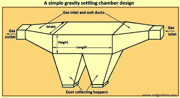
그림 1 간단한 중력 침전 챔버 설계
침전 챔버의 성능을 분석할 때 핵심 기능은 장치를 통과하는 가스 흐름의 특성입니다. 이와 관련하여 세 가지 기본적인 이상화된 유동 상황은 구별될 수 있습니다. 즉 (i) 층류, (ii) 입자의 수직 혼합이 없는 플러그 유동(단면 전체에 걸쳐 균일한 속도), (iii) 완전 수직 혼합이 있는 플러그 유동 입자.
층류는 포물선형 속도 프로파일이 특징입니다. 이러한 흐름은 난류 흐름으로의 전환에 대한 것보다 낮은 레이놀즈 수에 대해서만 실현됩니다. 층류에서 챔버 바닥 위의 높이 'h'에 있는 입자가 침강하는 데 필요한 시간은 'h/V'이고 여기서 V는 입자의 침강 속도입니다. 층류에서는 입자의 수직 혼합이 없습니다. 브라운 운동의 효과는 일반적으로 침전으로 인한 꾸준한 하향 운동에 비해 무시됩니다.
층류 침전 챔버에서 가스 속도 프로파일은 포물선이고 중심 유선 아래의 입자가 침전됨에 따라 더 느리게 움직이는 유체를 만나므로 챔버 내 체류 시간이 더 높은 유선에 있었던 것보다 증가합니다. 반면에 처음에 중심 유선형 위에 있는 입자는 중심 유선형을 통과할 때까지 떨어질 때 더 빠르게 움직이는 유선형을 만납니다.
두 번째 흐름 범주는 입자의 수직 혼합이 없는 플러그 흐름입니다. 이러한 유형의 흐름은 어떤 의미에서는 입자의 수직 혼합이 여전히 무시된다는 점에서 층류 흐름에 대한 근사치이지만 평평한 속도 프로파일이 가정되고 입자가 모두 침전 속도로 침전됩니다. 두 번째 유형의 유동 상황은 입자의 수직 혼합이 없는 플러그 유동의 상황입니다. 이 상황에서 입자는 챔버 입구 전체에 균일하게 분포되어 있다고 가정합니다. 입자가 포집되는지 여부는 포집 표면 위의 입구 높이 'h'에 의해서만 결정됩니다. 임계 높이 'h*'는 'h'보다 작거나 같은 'h'로 들어오는 모든 입자가 수집되고 'h'가 'h*'보다 큰 입자가 수집되도록 정의할 수 있습니다.
세 번째 범주인 철저한 수직 혼합이 있는 플러그 흐름은 난류입니다. 난류 침전 챔버에서 가스 속도는 난류 혼합으로 인해 챔버 전체에 걸쳐 균일하다고 가정합니다. 더욱이, 챔버 코어의 난류 혼합은 입자가 침강하는 경향을 압도하고 챔버 전체에 수직으로 균일한 입자 농도를 유지합니다. 침전에 의한 제거는 챔버 바닥의 얇은 층에서 발생한다고 가정할 수 있습니다.
직사각형 수로의 흐름은 레이놀즈 수가 4,000보다 크면 난류라고 가정할 수 있습니다. 층류 침전 챔버에서 입자는 챔버 바닥 위의 모든 높이에서 침전되며 분석의 핵심은 입자가 유선을 가로질러 떨어질 때 입자의 전체 체류 시간을 계산하는 것입니다. 난류 침전 챔버에서 수집 메커니즘은 궁극적으로 중력 하에서 입자의 침전을 기반으로 하지만 층류 챔버에서의 수집 메커니즘과는 다소 다릅니다. 그 차이는 챔버의 난류로 인한 것입니다. 챔버의 벌크 흐름에서 난류 혼합은 입자가 흐름에 압도되어 침전되지 않을 정도로 충분히 강력합니다. 난류 혼합이 챔버 높이에 걸쳐 균일한 입자 농도를 유지한다고 가정합니다. 챔버 바닥 근처에 입자가 바닥까지 짧은 거리에 정착하는 얇은 층이 존재한다고 가정할 수 있습니다. 따라서 흐름의 중심부에서 격렬하게 혼합된 입자가 이 층으로 들어가면 바닥에 가라앉습니다.
사이클론 분리기
사이클론 분리기는 가스에서 입자를 분리하기 위해 회전하는 가스 흐름에 의해 생성된 원심력을 활용하는 가스 청소 장치입니다. 표준 접선 입구 수직 역류 사이클론 분리기가 그림 2에 나와 있습니다. 가스 흐름은 사이클론의 곡선 형상을 따르도록 강제되는 반면 흐름에 있는 입자의 관성은 입자가 외부 벽쪽으로 이동하도록 하여 충돌하고 모은. 반경 'r'의 원형 경로에서 접선 속도 'vA'로 움직이는 질량 'm'의 입자는 'm(vA)2/r'의 원심력에 의해 작용합니다. 'vA' =10m/s, 'r' =0.5m의 일반적인 값에서 이 힘은 동일한 입자에 대한 중력의 20.4배입니다. 따라서 침전 단독에 비해 입자에 대한 실질적으로 강화된 힘이 사이클론 기하학에 대해 달성될 수 있음을 알 수 있습니다.
사이클론에서 회전하는 가스 흐름의 입자는 장치를 통해 흐르면서 점차적으로 외벽에 더 가깝게 이동합니다. 그림 2에서 볼 수 있듯이 가스 흐름은 장치의 한쪽 끝에서 다른 쪽 끝으로 흐를 때 여러 번 완전히 회전할 수 있습니다. 사이클론 분리기의 설계를 위해 주어진 가스 유량, 내부 및 외부 반경, 사이클론 본체의 길이는 주어진 크기의 입자에 대해 원하는 포집 효율이 달성되도록 보장해야 합니다. 사이클론 본체의 길이는 가스 흐름 속도를 통해 가스 흐름에 의해 실행되는 회전 수와 관련이 있기 때문에 설계는 종종 지정된 수집 효율성을 달성하는 데 필요한 회전 수를 계산하는 것으로 구성됩니다.
회전 운동이 가스 흐름에 전달되는 방식이 다른 사이클론 분리기에 사용할 수 있는 다양한 디자인이 있습니다. 기존의 사이클론은 (i) 역류식 사이클론(접선 입구 및 축 방향 입구), (ii) 직선형 흐름 사이클론, (iii) 임펠러 수집기의 세 가지 범주로 나눌 수 있습니다.
그림 2는 접선 입구가 있는 기존의 역류 사이클론을 보여줍니다. 더티 가스는 사이클론의 상단으로 들어가고 접선 진입으로 인해 회전 운동을 합니다. 입자는 원심력에 의해 벽으로 밀려난 다음 중력에 의해 벽 아래로 떨어집니다. 사이클론의 바닥에서 가스 흐름이 역전되어 사이클론의 상단에 남겨지는 내부 코어를 형성합니다. 역류 축방향 유입 사이클론에서 유입 가스는 사이클론의 축 아래로 도입되고 원심 운동은 상단에 있는 영구 베인에 의해 전달됩니다.
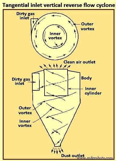
그림 2 접선 입구 수직 역류 사이클론
직선형 사이클론에서 공기의 내부 소용돌이는 방향을 바꾸는 것이 아니라 아래쪽에 남고 초기 원심 운동은 위쪽의 베인에 의해 전달됩니다. 이 유형은 큰 입자를 제거하기 위한 사전 세척제로 자주 사용됩니다. 이 사이클론의 주요 장점은 낮은 압력 강하와 높은 체적 유량입니다.
임펠러 수집기에서 가스는 날개가 많은 임펠러에 수직으로 들어가고 임펠러에 의해 주변으로 휩쓸려 나가는 반면 입자는 사이클론 주변의 환형 슬롯으로 던져집니다. 이 사이클론의 주요 장점은 소형입니다. 사이클론의 주요 단점은 사이클론의 고체 축적으로 인해 막히는 경향이 있다는 것입니다.
사이클론은 금속 또는 세라믹 모든 재료로 구성할 수 있습니다. 고온, 연마 입자 또는 부식성 대기를 견딜 수 있습니다. 수집된 입자가 벽을 따라 호퍼로 쉽게 미끄러질 수 있도록 내부 표면이 매끄럽게 해야 합니다. 사이클론에는 움직이는 부품이 없으므로 일반적으로 작동이 간단하고 비교적 유지 보수가 필요 없습니다. 낮은 자본 비용과 유지 관리가 필요 없는 작동으로 ESP와 같은 보다 효율적인 최종 제어 장치를 위한 사전 세척제로 사용하기에 이상적입니다. 사이클론은 전통적으로 상대적으로 효율이 낮은 집진기로 간주되어 왔지만 현재 사용 가능한 일부 사이클론은 5마이크로미터보다 큰 입자에 대해 98%보다 높은 효율을 달성할 수 있습니다. 일반적으로 사이클론은 15마이크로미터에서 20마이크로미터보다 큰 입자에 대해 일상적으로 90%의 효율을 달성합니다.
그림 3은 r3에서 방사 가스 흐름의 수평면에 접선 방향으로 들어가는 입자가 고려됨을 보여줍니다. 'm(vA)2/r'의 원심력 때문에 입자는 흐름 유선을 가로질러 바깥쪽으로 경로를 따릅니다. 속도 벡터에는 접선 성분(vA)과 방사 성분(Vr)이 있습니다. 축 성분(vZ)도 있습니다.
소위 층류 사이클론 분리기는 층류 침전 챔버의 의미에서 층류가 아니라 그림 3과 같이 유선이 사이클론의 윤곽을 따르는 마찰 없는 흐름입니다.
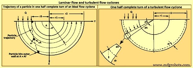
그림 3 층류 및 난류 사이클론
난류 사이클론 분리기의 모델은 그림 3에 나와 있습니다. 난류 혼합으로 인해 입자 농도는 사이클론 전체에 걸쳐 균일하다고 가정되며, 난류 흐름 침전 챔버의 경우와 같이 외벽.
사이클론 수집 효율은 (i) 입자 크기, (ii) 입자 밀도, (iii) 유입 가스 속도, (iv) 사이클론 본체 길이, (v) 가스 회전 수 및 (vi) 사이클론 벽의 평활도가 증가함에 따라 증가합니다. 한편, 사이클론 효율은 (i) 사이클론 직경, (ii) 가스 배출 덕트 직경 및 (iii) 가스 유입 면적이 증가함에 따라 감소합니다. 치수 비율이 고정된 특정 사이클론의 경우 사이클론 직경이 작아질수록 포집 효율이 높아집니다. 사이클론 분리기의 설계는 수집 효율성, 압력 강하 및 크기 사이에서 절충안을 나타냅니다. Higher efficiencies need higher pressure drops (i.e., inlet gas velocities) and larger sizes (i.e. body length). The dimensions required to specify a tangential-entry, reverse-flow cyclone are shown in Fig 4.
Besides collection efficiency the other major consideration in cyclone specification is pressure drop. While higher efficiencies are achieved by forcing the gas through the cyclone at higher velocities, to do so results in an increased pressure drop. Since increased pressure drop needs increased energy input into the gas, there is ultimately an economic trade-off between collection efficiency and operating cost. Cyclone pressure drops normally range from 250 Pa to 4,000 Pa.
Electrostatic precipitator
ESP is one of the most widely used particulate control device. It has wide size ranges. The ESP chamber consists of two electrodes, the discharge and the collecting electrodes. Between the electrodes, the gas contains free electrons, ions, and charged particles. The species contributing to the space charge density are ions, electrons, and charged particles. The gas molecules capture all the free electrons so that only the ions and charged particles contribute space charge density. Actually, ionic current flows in the direction of the electric field consisting of ions charged with the same polarity as the charging electrode and moving to the collecting electrode. The ions migrate to the collecting electrode with a velocity large enough to be unaffected by the turbulent flow in the chamber.
The basic principle of operation of the ESP is that the particles are charged, and then an electric field is imposed on the region through which the particle-laden gas is flowing, exerting an attractive force on the particles and causing them to migrate to the oppositely charged electrode at right angles to the direction of gas flow. ESP differs from mechanical methods of particle separation in that the external force is applied directly to the individual particles rather than indirectly through forces applied to the entire gas stream (e.g. in a cyclone separator). Particles collect on the electrode. If the particles collected are liquid, then the liquid flows down the electrode by gravity and it is removed at the bottom of the device. If the particles are solid, the collected layer on the electrode is removed periodically by rapping the electrode.
Particle charging is achieved by generating ions by means of a corona established surrounding a highly charged electrode like a wire. The electric field is applied between that electrode and the collecting electrode. If the same pair of electrodes serves for particle charging and collecting, the device is called a single-stage ESP (Fig 4). A wire serving as the discharge electrode is suspended down the axis of a tube and held in place by a weight attached at the bottom. The sides of the cylinder form the collecting electrode. The collected particles which form a layer on the collecting electrode are removed to the dust hopper by rapping the collecting electrode. In a two-stage ESP, separate electrode pairs perform the charging and collecting functions.
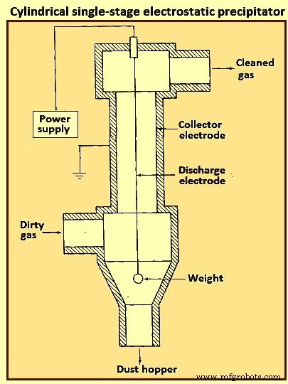
Fig 4 Cylindrical single-stage electrostatic precipitator
Most industrially generated particles are charged during their formation by such means as flame ionization and friction, but normally only to a low or moderate degree. These natural charges are far too low for electrostatic precipitation. The high-voltage DC (direct current) corona is the most effective means for particle charging and is universally used for electrostatic precipitation. The corona is formed between an active high voltage electrode such as a fine wire and a passive ground electrode such as a plate or pipe. The corona surrounding the discharge electrode can lead to the formation of either positive or negative ions which migrate to the collecting electrode. The ions, in migrating from the discharging to the collecting electrode, collide with the particulate matter and charge the particles.
Since the gas molecule ions are many orders of magnitude smaller than even the smallest particles and because of their great number, virtually all particles that flow through the device become charged. The charged particles are then transported to the collecting electrode, to which they are held by the electrostatic attraction. The particles build a thickening layer on the collecting electrode. The charge slowly bleeds from the particles to the electrode. As the layer grows, the charges on the most recently collected particles are to be conducted through the layer of previously collected particles. The resistance of the dust layer is called the dust resistivity.
As the particle layer grows in thickness, the particles closest to the plates lose most of their charge to the electrode. As a result, the electrical attraction between the electrode and these particles is weakened. However, the newly arrived particles on the outside layer have a full charge. Because of the insulating layer of particles, these new particles do not lose their charge immediately and thus serve to hold the entire layer against the electrode. Finally, the layer is removed by rapping, so that the layer breaks up and falls into a collecting hopper. ESPs are normally employed for gas cleaning when the volumetric throughput of gas is high.
The mechanism for particle charging in a ESP is the generation of a supply of ions which attach themselves to the particles. The corona is the mechanism for forming ions. The corona can be either positive or negative. A gas normally has a few free electrons and an equal number of positive ions, a situation which is exploited in generating a corona. When a gas is placed between two electrodes, small amount of current results as the free electrons migrate to the positive electrode and the positive ions migrate to the negative electrode.
In the positive corona discharge electrode, the wire in the cylindrical ESP (Fig 4) is at a positive potential. The few free electrons normally present in the gas migrate toward the wire. As the electrons approach the wire, the electrons’ energy is increased because of an increase in the attractive force. These free electrons collide with gas molecules, the collision leading in some cases to the ejection of an electron from the molecule, producing two free electrons and a positive ion. The two free electrons continue toward the positive electrode, gaining energy, until they collide with two more gas molecules, producing four free electrons and two positive ions. This process is referred to as an electron avalanche.
The positive ions formed migrate to the negative electrode. It is these positive ions which migrate across the entire device to the negative electrode that collide with and attach to the particles in the gas. The region immediately surrounding the wire in which the electron avalanche is established is the corona. Thus, with a positive corona the particles become positively charged. The term ‘corona’ arises from the fact that the electron avalanche is frequently accompanied by the production of light. In the negative corona the discharge electrode is maintained at a negative potential.
The electron avalanche begins at the outer surface of the wire and proceeds radially outward. Close to the wire the electrons are sufficiently energetic to form positive ions upon collision with gas molecules, thus initiating the electron avalanche. The positive ions formed migrate the short distance to the wire. As the electrons migrate outward into a region of lower electric field strength, they are slowed down by collisions with gas molecules. These electrons eventually have lower energy than those which are accelerated toward the positive electrode in the positive corona. These relatively low energy electrons, rather than ejecting an electron from the gas molecule upon collision, are absorbed by the gas molecules to produce negative ions. The formation of negative ions, which begins to occur at the outer edge of the corona, essentially absorbs all the free electrons produced in the electron avalanche at the wire surface. These negative ions then migrate to the positive electrode, in the course of which attaching to gas molecules and forming negative ions.
For a negative corona to be effective, it is necessary that the gas molecules can absorb free electrons to form negative ions. Sulphur dioxide is one of the best electron absorbing gases of those present in flue gases. Oxygen, CO2, and H2O are also effective electron absorbers. The negative corona is normally more stable than the positive corona, so it is preferred in most industrial applications. A by-product of the negative corona is the production of ozone (O3). The positive corona does not need an electron-absorbing gas.
As the ESP is operated, a layer of the collected material builds up on the collecting electrode. Particle deposits on the precipitator collection surface are to possess at least a small degree of electrical conductivity in order to conduct the ion currents from the corona to ground. The minimum conductivity required is around 10 to the power -10 per ohm-centimeter (resistivity of 10 to the power 10 ohm-centimeter). This conductivity is small compared to that of ordinary metals but is much greater than that of good insulators such as silica and most plastics. The resistivity of a material is determined by establishing a current flow through a slab of known thickness of the material.
As long as the resistivity of the collected dust layer is less than about 10 to the power 10 ohm-centimeter, the layer surrender its charge to the electrode. At the room temperature, a typical dust has a resistivity of around 10 to the power 8 ohm-centimeter. This is because of a layer of water on the surface of the particles. As the temperature is increased beyond 100 deg C, the water is evaporated and the resistivity increases to a value characteristic of the collected solids. When the resistivity of the layer exceeds around 10 to the power 10 ohm-centimeter, the potential across the layer increases so that the voltage which can be maintained across the ESP decreases and the collection efficiency decreases. The electrical resistivity of collected particulate matter depends on its chemical composition, the constituents of the gas, and the temperature.
Particle charging in ESP occurs in the gas space between the electrodes where the gas ions generated by the corona bombard and become attached to the particles. The gas ions can reach concentrations as high as 10 to the power 15 ions per cubic meter. The level of charge attained by a particle depends on the gas ion concentration, the electric field strength, the conductive properties of the particle, and the particle size. A 1 micrometer particle typically acquires the order of 300 electron charges, whereas a 10 micrometer particle can attain 30,000 electron charges. Predicting the level of charge acquired by a particle is necessary in order to predict the particle’s migration velocity, on the basis of which the collection efficiency can be calculated for a given set of operating conditions.
There are actually two mechanisms by which particles become charged in an ESP. In the first mechanism particle charging occurs when ions which are migrating toward the collecting electrode encounter particles to which they become attached. In migrating between the electrodes the ions follow the electric flux lines, which are curves everywhere tangent to the electric field vector. When the particle first enters the device and is uncharged, the electric flux lines deflect toward the particle, resulting in the capture of even a larger number of ions than are captured if the ions have followed their normal path between the electrodes. As the particle becomes charged, ions begin to be repelled by the particle, reducing the rate of charging. Eventually, the particle acquires a saturation charge and charging ceases. This mechanism is called ion bombardment or field charging.
The second mode of particle charging is diffusion charging, in which the particle acquires a charge by virtue of the random thermal motion of ions and their collision with and adherence to the particles. Diffusion charging occurs as the ions in their random thermal motion collide with a particle and surrender their charge to it. In that sense the mechanism of diffusion charging is identical to that of the diffusion of uncharged vapour molecules to the surface of a particle. However, because both the particle and the ions are charged, the random thermal motion of the ions in the vicinity of a particle is influenced by an electrostatic force. This force gives rise to a tendency of the ions to migrate away from the particle as the particle charge increases. The overall flux of ions to a particle hence is both the random diffusive motion and the electrical migration.
The theories of both field and diffusion charging, in their full generality, are quite complex and have received a great deal of attention. Strictly speaking, field and diffusion charging occur simultaneously once a particle enters an ESP, and hence to predict the overall charge acquired by a particle, one is to consider the two mechanisms together. However, since the diffusion charging is predominant for particles smaller than around 1 micrometer in diameter and field charging is predominant for particles larger than around 1 micrometer, the two mechanisms frequently are treated in ESP design as if they occur independently. In doing so, one estimates the total charge on a particle as the sum of the charges resulting from each of the two separate mechanisms.
Filtration of particles from gas streams
A major class of particulate air pollution control devices relies on the filtration of particles from gas streams. A variety of filter media is employed, including fibrous beds, packed beds, and fabrics. Fibrous beds used to collect airborne particles are typically quite sparsely packed, usually only around 10 % of the bed volume being fibers. Packed bed filters consist of solid packing normally in a tube and tend to have higher packing densities than do fibrous filters. Both fibrous and packed beds are widely used in the ventilation systems. Fabric filters are frequently used to remove solid particles from industrial gases, whereby the dusty gas flows through fabric bags and the particles accumulate on the cloth.
The physical mechanisms by which the filtration is accomplished vary depending on the mode of filtration. Conventional sparsely packed fibrous beds can be viewed as assemblages of cylinders. In such a filter, the characteristic spacing between fibers is much larger than the size of the particles being collected. Thus the mechanism of collection is not simply sieving, in which the particles are trapped in the void spaces between fibers. Rather, the removal of particles occurs by the transport of particles from the gas to the surface of a single collecting element. Because the filtration mechanisms in a fibrous bed can be analyzed in terms of a single collector, it is possible to describe them in considerable theoretical detail.
Packed-bed filters are sometimes viewed as assemblages of interacting, but essentially separate, spherical collectors, although the close proximity of individual packing elements casts doubt as to the validity of this approach. Because of the relatively closer packing in packed-bed filters, and the resulting difficulty of describing the particle collection process in clean theoretical terms, predicting collection in such systems is more empirically based than for fibrous filters. Fabric filter efficiencies must be predicted strictly empirically since the accumulated particle layer actually does the collecting.
A fibrous filter bed is viewed as a loosely packed assemblage of single cylinders. Even though the fibers are oriented in all directions in the bed, from a theoretical point of view the bed is treated as if every fiber is normal to the gas flow through the bed. The solid fraction of the filter is normally of the order of only 10 %. In addition, each fiber acts more or less independently as a collector. Thus, to compute the particle removal by a filter bed, one basically needs to determine the number of fibers per unit volume of the bed and then multiply that quantity by the efficiency of a single fiber.
The basis of predicting the collection efficiency of a filter bed is the collection efficiency of a single filter element in the bed. The filter element is taken as an isolated cylinder normal to the gas flow. Three distinct mechanisms as given below can be identified whereby particles in the gas reach the surface of the cylinder.
As per the first mechanism, the particles in a gas undergo Brownian diffusion which brings some particles in contact with the cylinder due to their random motion as they are carried past the cylinder by the flow. A concentration gradient is established after the collection of a few particles and acts as a driving force to increase the rate of deposition over that which occurs in the absence of Brownian motion. Because the Brownian diffusivity of particles increases as particle size decreases, it is normally expected that this removal mechanism is the most important for very small particles. When analyzing collection by Brownian diffusion, the particles are treated as diffusing mass-less points.
As per the second mechanism, interception takes place when a particle, following the streamlines of flow around a cylinder, is of a size sufficiently large that its surface and that of the cylinder come into contact. Thus, if the streamline on which the particle centre lies is within a distance Dp /2 of the cylinder, interception occurs. Here Dp is the particle diameter.
As per the third mechanism, inertial impaction occurs when a particle is unable to follow the rapidly curving streamlines around an obstacle and, because of its inertia, continues to move toward the obstacle along a path of less curvature than the flow streamlines. Thus, collision occurs because of the particle’s momentum. It is to be noted that the mechanism of inertial impaction is based on the premise that the particle has mass but no size, whereas interception is based on the premise that the particle has size but no mass.
Collection can also result from electrostatic attraction when either particles or fiber or both possess a static charge. These electrostatic forces can be either direct, when both particle and fiber are charged, or induced, when only one of them is charged. Such charges are normally not present unless deliberately introduced during the production of the fiber.
The size ranges in which the various mechanisms of collection are important are (i) Inertial impaction – greater than 1 micrometer, (ii) Interception – greater than 1 micrometer, (iii) diffusion – less than 0.5 micrometer, and (iv) electrostatic attraction – 0.01 micrometer to 5 micrometer. It is normal to analyze the mechanisms of collection separately and then combine the individual efficiencies to give the overall collection efficiency for the cylinder or other obstacle.
Most developments of particle collection assume, for lack of better information, that particles transported to the surface of a fiber are retained by the fiber. Experiments have shown, however, that for a variety of substances and filter media, the fraction of particles striking the collector surface which adhere is generally less than unity and can in some cases be as low as 0.5.
Industrial fabric filtration is normally accomplished in a so-called bag- house, in which the particle-laden gases are forced through filter bags. Particles are normally removed from the bags by gravity. Fig 5 shows three bag-house designs, in which cleaning is accomplished by vibration (Fig 5a), air jet [Fig 5b), or traveling ring [Fig 5c).
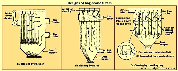
Fig 5 Designs of bag house filters
The fabric filtration process consists of three phases. First, particles collect on individual fibers by the above described mechanisms. Then an intermediate stage exists during which particles accumulate on previously collected particles, bridging the fibers. Finally, the collected particles form a cake in the form of a dust layer which acts as a packed bed filter for the incoming particles. As the dust layer accumulates, the pressure drop across the filter increases, and periodically the dust layer is to be dislodged into the hopper at the bottom to ‘regenerate’ the fabric bag. High efficiencies are attainable with fabric filters, particularly in treating combustion gases from the technological processes. To the extent that effective operation of an ESP depends on the presence of SO2 in the gas as an ionizable species, fabric filters can operate with no loss of efficiency with low-sulphur level.
Fabric filters consist of semi-permeable woven or felted materials which constitute a support for the particles to be removed. A brand-new woven filter cloth has fibers roughly 100 micrometers to 150 micrometers in diameter with open spaces between the fibers of 50 micrometers to 75 micrometers. Initially, the collection efficiency of such a cloth is low because most of the particles pass directly through the fabric. However, deposited particles quickly accumulate, and it is the deposited particle layer that enables the high-efficiency removal once a uniform surface layer has been established.
Although fiber mat filters are similar in some respects to fabric filters, they do not depend on the layer of accumulated particles for high efficiency. Fiber mat filters generally are not cleaned but are discarded. They are ordinarily used when particle concentrations are low, so that reasonable service life can be achieved before discarding.
In a fabric filter the particle layer performs the removal task. As the layer of collected particles grows in thickness, there is an increase in the pressure drop across the particle layer and the underlying fabric. The two major considerations in the design of a fabric filter assembly are the collection efficiency and the pressure drop as a function of time of operation (since the last cleaning). The collection efficiency depends on the local gas velocity and the particle loading on the fabric.
Fabric filters offer the several advantages such as (i) they can achieve very high collection efficiencies even for very small particles, (ii) they can be used for a wide variety of particles, (iii) they can operate over a wide range of volumetric flow rates, and (iv) they need only moderate pressure drops. The limitations of fabric filters are namely (i) operation is to be carried out at temperatures lower than that at which the fabric is destroyed, or its life is shortened to an uneconomical degree, (ii) gas or particle constituents which attack the fabric or prevent proper cleaning, such as sticky particles difficult to dislodge, are to be avoided, and (iii) bag houses need large floor areas. The advantages of fabric filter bag houses clearly outweigh their limitations.
Wet collectors
Wet collectors, or scrubbers, employ water washing to remove particles directly from a gas stream. Scrubbers can be grouped broadly into two main classes namely (i) those in which an array of liquid drops (sprays) form the collecting medium, and (ii) those in which wetted surfaces of various types constitute the collecting medium. The first class includes spray towers and venturi scrubbers, while the second includes plate and packed towers.
Scrubbing is a very effective means of removing small particles from a gas. Removal of particles results from collisions between particles and water drops. In the humid environment of a scrubber, small, dry particles also grow in size by condensation of water and thereby become easier to remove. Re-entrainment of particles is avoided since the particles become trapped in droplets or in a liquid layer. A scrubber also provides the possibility of simultaneously removing soluble gaseous pollutants. The particle-laden scrubbing liquid is to be disposed of, a problem not encountered in dry methods of gas cleaning.
A spray scrubber is a device in which a liquid stream is broken into drops, approximately in the range 0.1 mm to 1 mm in diameter, and introduced into the particle laden gas stream. The array of moving drops becomes a set of targets for collection of the particles in the gas stream. Collection efficiency is computed by considering the efficiency of a single spherical collector and then summing over the number of drops per unit volume of gas flow. The relative motion between the drops and particles is an important factor in the collection efficiency since capture occurs by impaction and direct interception. Diffusion is also important for smaller particles.
There are two general types of spray scrubbers. The first class comprises those having a preformed spray where drops are formed by atomizer nozzles and sprayed into the gas stream. These include (i) counter-current gravity tower, where drops settle vertically against the rising gas stream, (ii) cross-current tower, where drops settle through a horizontal gas stream, and (iii) co-current tower, where spray is horizontal into a horizontal gas stream.
The second class comprises those in which the liquid is atomized by the gas stream itself. Liquid is introduced more or less in bulk into a high-velocity gas flow which shatters the liquid into drops. Devices in this class are called venturi scrubbers since the high velocity gas flow is achieved in a venturi (a contraction). Fig 6 shows four types of wet collection equipment.
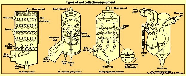
Fig 6 Types of wet collection equipment
The simplest type of wet collector is a spray tower into which water is introduced by means of spray nozzles (Fig 6a). Gas flow in a spray chamber is counter-current to the liquid, the configuration leading to maximum efficiency. Collection efficiency can be improved over the simple spray chamber with the use of a cyclonic spray tower, as shown in Fig 6b. The liquid spray is directed outward from nozzles in a central pipe. An unsprayed section above the nozzles is provided so that the liquid drops with the collected particles have time to reach the walls of the chamber before exit of the gas. An impingement plate scrubber, as shown in Fig 6c, consists of a tower containing layers of baffled plates with holes (5,000 to 50,000 per square meter) through which the gas must rise and over which the water must fall. Highest collection efficiencies of wet collectors are obtained in a venturi scrubber, shown in Fig 6d, in which water is introduced at right angles to a high-velocity gas flow in a venturi tube, resulting in the formation of very small water droplets by the flow and high relative velocities of water and particles. The high gas velocity is responsible for the breakup of the liquid. Aside from the small droplet size and high impingement velocities, collection is enhanced through particle growth by condensation. Different types of particle scrubbing devices are described below.
Plate scrubber – It is a vertical tower containing one or more horizontal plates (trays). Gas enters the bottom of the tower and must pass through perforations in each plate as the gas flows counter-current to the descending water stream. Plate scrubbers are normally named for the type of plates they contain (e.g. sieve plate tower). Collection efficiency increases as the diameter of the perforations decreases. A cut diameter, that collects with 50 % efficiency, of around 1 micrometer aerodynamic diameter can be achieved with 3.2 mm diameter holes in a sieve plate.
Packed-bed scrubber – It operates similarly to packed-bed gas absorber. Collection efficiency increases as packing size decreases. A cut diameter of 1.5 micrometers aerodynamic diameter can be attained in columns packed with 2.5 cm elements.
Spray scrubber – In this scrubber, particles are collected by liquid drops which have been atomized by spray nozzles. Horizontal and vertical gas flows are used, as well as spray introduced co-current, counter-current, or cross-flow to the gas. Collection efficiency depends on droplet size, gas velocity, liquid / gas ratio, and droplet trajectories. For droplets falling at their terminal velocity, the optimum droplet diameter for fine-particle collection lays in the range 100 micrometers to 500 micrometers. Gravitational settling scrubbers can achieve cut diameters of around 2 micrometers. The liquid / gas ratio is in the range 0.001 cum to 0.01 cum per cum of gas treated.
Venturi scrubber – A moving gas stream is used to atomize liquids into droplets. High gas velocities (60 m/sec to 120 m/s) lead to high relative velocities between gas and particles and promote collection.
Cyclone scrubber – Drops can be introduced into the gas stream of a cyclone to collect particles. The spray can be directed outward from a central manifold or inward from the collector wall.
Baffle scrubber – In this scrubber, there are changes in gas flow velocity and direction induced by solid surfaces.
Impingement-entrainment scrubber – The gas is forced to impinge on a liquid surface to reach a gas exit. Some of the liquid atomizes into drops which are entrained by the gas. The gas exit is designed so as to minimize the loss of entrained droplets.
Fluidized-bed scrubber – A zone of fluidized packing is provided where gas and liquid can mix intimately. Gas passes upward through the packing, while liquid is sprayed up from the bottom and / or flows down over the top of the fluidized layer of packing.
The collection efficiency of wet collectors can be related to the total energy loss in the equipment. The higher is the scrubber power per unit volume of gas treated, the better is the collection efficiency. Almost all the energy is introduced in the gas, and thus the energy loss can be measured by the pressure drop of gas through the unit. The major advantage of wet collectors is the wide variety of types, allowing the selection of a unit suitable to the particular removal problem. As regards disadvantages, high pressure drops (and hence energy requirements) are to be maintained, and the handling and disposal of large volumes of scrubbing liquid are to be undertaken.
In case of spray scrubbing, the conceptually simplest of the devices is a gravity spray chamber. Water droplets are introduced at the top of an empty chamber through atomizing nozzles and fall freely at their terminal settling velocities counter-currently through the rising gas stream. The particle-containing liquid collects in a pool at the bottom and is to be pumped out for treatment to remove the solids, and the cleaned liquid is normally recycled to the tower. The overall efficiency of a spray tower increases as the collection efficiency of a single drop increases, as the length of the chamber increases, and as the ratio of the volumetric flow rate of water to that of gas increases. It increases as the diameter of the drops decreases.
Venturi scrubbers are used when high collection efficiencies are needed and when most of the particles are smaller than 2 micrometers in diameter. There are a number of examples, in fact, where a venturi scrubber is the only practical device for a gas-cleaning application. If the particles to be removed are sticky, flammable, or highly corrosive, for example, ESPs and fabric filters cannot be used. Venturi scrubbers are also the only high-efficiency particulate collectors which can simultaneously remove gaseous species from the effluent stream.
The distinguishing feature of a venturi scrubber is a constricted cross section or throat through which the gas is forced to flow at high velocity. A typical venturi scrubber configuration is shown in Fig 7. The configuration includes a converging conical section where the gas is accelerated to throat velocity, a cylindrical throat, and a conical expander where the gas is slowed down. Liquid can be introduced either through tangential holes in the inlet cone or in the throat itself. In the former case, the liquid enters the venturi as a film on the wall and flows down the wall to the throat, where it is atomized by the high-velocity gas stream. In the latter, the liquid is injected perpendicular to the gas flow in the throat, atomized, and then accelerated. Gas velocities in the range 60 m/sec to 120 m/sec are achieved, and the high relative velocity between the particle laden gas flow and the droplets promotes collection. The collection process is essentially complete by the end of the throat. Because they operate at much higher velocities than ESPs precipitators or bag houses, venturi scrubbers are physically smaller and can be economically made of corrosion-resistant materials. Venturis have the simplest configuration of the scrubbers and are the smallest in size. Fig 7 shows the comparison of the efficiency of venturi scrubber with the efficiencies of other gas cleaning devices.
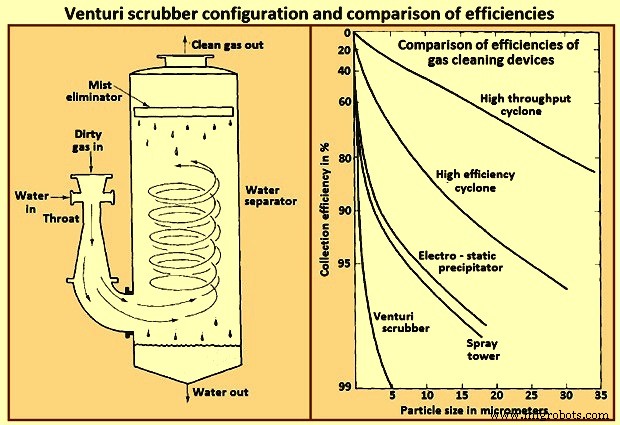
Fig 7 Venturi scrubber configuration and comparison of efficiencies
A typical range of liquid to gas flow rate ratios for a venturi scrubber is 0.001 cum to 0.003 cum of liquid per cum of gas. At the higher liquid / gas ratios, the gas velocity at a given pressure drop is reduced, and at lower ratios, the velocity is increased. For gas flow rates exceeding about 1,000 cum / minute venturi scrubbers are normally constructed in a rectangular configuration in order to maintain an equal distribution of liquid over the throat area.
제조공정
금형에서 새 주물 제거 녹고 붓는 것처럼 시각적으로 극적이지는 않지만 새로운 금속 주물을 흔드는 것은 여전히 인상적인 경험입니다. 주물이 처음 주형에서 김을 내뿜을 때 모래 파편과 과도한 금속 재료로 덮여 있습니다. 셰이크아웃, 클리닝, 게이트&라이저 제거, 마무리 기계를 거쳐야 일을 하면서 뼈저리게 흔들리는 라켓을 만든다. 이 과정이 끝나면 주조물은 최종 형태가 되지만 열처리, 분체 도장 및 검사가 여전히 필요할 수 있습니다. 금형에서 주물 제거 주형에서 주물을 제거하는 프로세스는 쉐이크아웃을 수행하기에 적절한 시간과 온
최적화된 실험실 운영을 위해 적절한 가스 분배가 필수적인 이유 Wouter Pronk, Swagelok 수석 현장 엔지니어 자신을 실험실 기술자라고 상상해 보십시오. 의도한 테스트 또는 분석을 수행할 때 특정 가스의 사용 지점에 접근합니다. 필요한 가스를 얻기 위해 메커니즘을 활성화하지만 흐름과 압력이 예상보다 낮습니다. 이것은 여러 가지 이유로 잠재적으로 문제가 됩니다. 수행 중인 테스트의 정확성이 반드시 신뢰할 수 있는 것은 아니며 테스트를 전혀 진행하지 못할 수도 있습니다. 문제의 원인을 찾기 위한 문제 해결에