

제조공정

산업 제조
폐수 및 수처리 기술
값싸고 풍부한 물은 수세기 동안 철강 산업이 당연하게 여겼던 생산 유틸리티였습니다. 그러나 현재 시나리오에서는 담수 가용성과 소비 간의 불균형이 증가함에 따라 수자원이 점점 부족해지고 있으며, 이에 따라 깨끗하고 안전한 물에 대한 접근은 현대 사회의 주요 과제 중 하나가 되었습니다. 물 수요는 (i) 인구 증가 및 가뭄 취약 지역으로의 이동, (ii) 급속한 산업 발전 및 1인당 물 사용량 증가, (iii) 인구 밀집 지역의 기상 패턴 변화로 이어지는 기후 변화로 인해 계속 증가하고 있습니다. 이로 인해 철강 산업은 새로운 물 제약 시대에 진입했습니다. 또한 지난 30년 동안 전 세계적으로 환경 오염에 대한 우려가 증가했으며 이에 따라 보다 엄격한 환경 규제가 공포되었습니다.
철강 산업은 냉각, 먼지 억제, 세척, 온도 조절(열처리), 폐기물(재, 슬러지, 스케일 등)의 운송 및 기타 용도를 포함하여 다양한 용도로 막대한 양의 담수를 사용합니다. 물은 점결탄 혼합물의 수분 함량을 제어하기 위한 물 첨가, 소결 혼합물의 펠릿화, 철광석 펠릿 생산 중 녹색 펠릿 만들기, 증기 및 이에 따른 전력 생산, 및 고로 슬래그 등의 과립화. 다량의 물을 사용하면 배출되어야 하는 상당한 양의 폐수도 발생합니다. 철강 산업의 폐수 배출은 수질 오염의 요인 중 하나로 인식되어 왔습니다. 제철소 공정에서 발생하는 폐수에는 많은 용해 물질과 용해되지 않은 물질 및 화학 물질이 포함되어 있습니다.
철강 공장 공정에 의한 공정수의 주요 용도에는 공정 배기 가스의 냉각 및 세정, 코크스 및 슬래그의 직접 냉각, 철강의 직접 냉각 및 세정, 제품 헹굼, 공정 용액 구성, 공정 장비의 직접 냉각 등이 있습니다. 제철소에서 사용하는 물의 대부분은 가공 설비의 비접촉 냉각용입니다. 물은 증기와 발전에도 사용됩니다.
공정 폐수는 철강 생산을 위한 공정, 제품, 부산물 또는 원자재와 직접 접촉하는 모든 폐수로 정의됩니다. 공정 폐수에는 슬래그 담금질, 장비 세척, 대기 오염 제어 장치, 헹굼 물 및 오염된 냉각수에서 나오는 폐수도 포함됩니다. 위생 폐수 및 우수는 공정 폐수로 간주되지 않습니다. 비접촉 냉각 폐수는 공정, 제품, 부산물 또는 원료와 직접 접촉하지 않는 냉각수입니다. 이 폐수는 공정 폐수로 간주되지 않습니다. 비공정 폐수는 유틸리티 폐수(수처리 잔류물, 보일러 블로우다운, 열회수 장비의 대기 오염 제어 폐수, 열병합 발전 설비에서 생성된 물), 지하수 정화 시스템, 건물 기초용 탈수수 및 생산 공정과 관련이 없는 기타 폐수 흐름
폐수 배출은 처리되거나 처리되지 않은 폐수가 수용 스트림으로 방출되는 것을 의미합니다. 배출은 처리장이나 수집 시스템의 오버플로에서 발생할 수 있습니다. 처리되지 않은 폐수 배출은 여러 가지 바람직하지 않은 조건을 유발할 수 있습니다. 여기에는 (i) 하천의 산소 고갈 및 악취 생성, (ii) 병원성 미생물의 존재로 인한 인체 건강에 대한 부정적인 영향, (iii) 슬러지 및 찌꺼기 축적, (iv) 수역의 성장으로 인한 수역의 부영양화가 포함됩니다. 폐수가 특정 양의 영양소를 함유할 수 있기 때문에 수생 식물 및 조류, (v) 폐수에 존재하는 유기 화합물의 분해로 인한 다량의 악취 가스 생성. 이러한 폐수 배출은 배출 전에 적절히 처리되지 않고 무해하게 만들어지지 않으면 해당 지역의 수역 오염에 기여합니다. 따라서 폐수 처리는 공장 부지를 떠나 자연 수역으로 배출되기 전에 반드시 이루어져야 합니다.
폐수 처리 방법은 환경에 대한 폐수 배출과 공중 보건에 대한 우려로 인한 불리한 조건에 대응하여 처음 개발되었습니다. 철강 산업의 폐수 처리는 제철소의 다양한 처리 장치에 따라 폐수의 특성이 다르기 때문에 상당히 복잡합니다.
순수한 물은 수소 2부와 산소 1부로 구성되어 있습니다. 자연에서 물에는 용해된 불순물이 많이 포함되어 있습니다. 실제로 물은 많은 물질을 녹일 수 있는 능력 때문에 '만능 용매'라고 불립니다. 증류수와 빗물도 일반적으로 불순물로 간주되는 암모니아와 같은 용해된 물질의 수준이 매우 낮기 때문에 '완전히' 순수한 것은 아닙니다. 지표수와 지하수에는 용해된 물질이 있습니다. 비가 내리면 질소 및 기타 가스가 흡수됩니다. 물은 땅을 통과할 때 나트륨, 칼슘, 철, 인, 마그네슘, 황산염과 같은 물질을 녹일 수 있습니다.
처리되지 않은 신선한 가정용 또는 원수는 퀴퀴한 냄새가 있으며 pH 범위는 6.5에서 8이며 색상은 회갈색입니다. 일반적으로 처리되지 않은 물에서 발견되는 오염 물질은 크게 (i) 유기 오염 물질, (ii) 무기 오염 물질, (iii) 병원체 및 (iv) 기타 오염 물질의 4가지 기본 분류로 나눌 수 있습니다. 폐수에 존재하는 대표적인 오염물질은 아래와 같습니다.
솔리드 – 폐수의 총 고형물은 용해된 고형물 또는 부유 고형물의 형태일 수 있습니다. 부유 고형물은 콜로이드성 고형물(침강할 수 없음) 또는 침강성 고형물의 형태일 수 있습니다. 부유 고형물(SS)은 처리되지 않은 폐수가 수중 환경으로 배출될 때 슬러지 퇴적물 및 혐기성 조건의 발달로 이어집니다. 총 부유 물질(TSS)에는 필터를 통과하는 모든 입자가 포함됩니다. TSS 수준이 증가함에 따라 수역은 다양한 수생 생물을 부양할 수 있는 능력을 잃기 시작합니다. 부유 고체는 햇빛으로부터 열을 흡수하여 수온을 높이고 결과적으로 용존 산소 수준을 감소시킵니다. 일부 고체는 부유 가능한 고체일 수도 있습니다. 이러한 부유성 고체는 일반적으로 오일 또는 그리스 입자로 구성되며 찌꺼기를 구성합니다. 찌꺼기는 표면 스키밍 장비로 가장 쉽게 제거됩니다.
생분해성 유기물 – 생분해성 유기물은 주로 단백질, 탄수화물 및 지방으로 구성됩니다. 생분해성 유기물은 주로 BOD(생화학적 산소 요구량)와 COD(화학적 산소 요구량)로 측정됩니다. 수질의 중요한 척도인 BOD는 20℃ 온도에서 5일 동안 물 샘플에 존재하는 유기물을 산화시키기 위해 박테리아 및 기타 유기체에 필요한 산소의 양을 측정합니다. COD는 반응에서 완전히 산화되지 않는 일부 방향족(벤젠, 톨루엔, 페놀 등)을 제외한 모든 유기 탄소를 측정합니다. COD는 화학적 산화 반응입니다. 높은 BOD와 COD는 수역의 낮은 산소 농도에 기여하고 함께 수역의 수생 생물에 부정적인 영향을 미칩니다. 생분해성 유기물의 생물학적 안정화는 처리되지 않은 상태로 환경에 배출될 경우 천연 산소 자원의 고갈과 패혈증 상태를 유발할 수 있습니다.
병원체 – 병원체는 질병을 유발하거나 유발할 수 있는 미생물입니다. 전염병은 폐수에 있는 병원체에 의해 전염될 수 있습니다.
영양소 – 질소와 인은 탄소와 함께 성장에 필수적인 영양소입니다. 수중 환경으로 배출될 때, 이러한 영양소는 바람직하지 않은 수중 생물의 성장으로 이어질 수 있습니다. 육지에 과량으로 배출될 경우 지하수를 오염시킬 수도 있습니다.
중요 오염 물질 – 발암성, 변이원성 또는 고급성독성이 알려지지 않았거나 의심되는 특성이 있는 유기 및 무기 화합물입니다. 폐수에서 이러한 화합물의 존재는 공중 보건상의 이유로 최소화하고 생물학적 처리 과정을 보호해야 합니다.
내화 유기물 – 이러한 유기물은 기존의 폐수 처리 방법에 저항하는 경향이 있습니다. 대표적인 예로는 계면활성제, 페놀, 농약이 있습니다. 이들 중 일부는 생물학적 처리 과정에 유독할 수 있습니다.
중금속 – 제철소의 다양한 단위에서 생성되는 폐수에 중금속이 존재할 수 있습니다. 이러한 중금속은 폐수가 식수원으로 사용되는 수역으로 방류되는 경우 제거해야 합니다. 중금속의 존재는 또한 농경지에서 바이오스 고형물(안정화된 폐기물 슬러지)의 재활용에 영향을 미칠 수 있습니다.
용해 무기물 – 칼슘, 나트륨, 황산염과 같은 무기 성분은 제철소의 일부 장치의 폐수에 존재할 수 있습니다. 폐수가 식수원으로 사용되는 수역으로 방류되는 경우 제거해야 합니다.
용해 화학물질 – 공정에 따라 폐수에 광범위한 용해 화학물질이 존재할 수 있습니다. 이를 위해서는 오염 물질의 유형, 농도, 흐름 및 생분해성의 용이성에 대한 신중한 평가가 필요합니다. 배출되는 물의 농도가 리터당 1밀리그램이면 물의 미적 품질과 투명도에 영향을 미치는 착색된 물이 생성될 수 있습니다. 광합성에도 영향을 미칩니다. 산과 알칼리는 pH가 낮거나 높은 상황을 만듭니다. 일부 화학 물질은 기존 처리 과정을 통해 분해하기 어려울 수 있습니다.
화합물에서 파생된 유기 오염물질에는 탄소가 포함되어 있습니다. 이러한 오염 물질은 생분해될 수 있으며, 이는 오염 물질이 박테리아 및 기타 미생물에 의해 소비될 수 있음을 의미합니다. 소비되는 과정에서 이러한 유기물은 폐수의 BOD로 측정할 수 있는 산소 요구량을 나타냅니다. 일부 유기 오염 물질(내화성 유기물)은 생분해에 내성이 있습니다. 무기 오염 물질은 생분해되지 않지만 미생물이 살기 위해 필요한 영양소가 될 수 있습니다. 이들은 일반적으로 폐수에 부유 고체 또는 용해된 무기물로 존재하는 화학 화합물(중요 오염 물질) 또는 금속입니다.
병원체는 인간이나 동물의 배설물이나 부적절하게 처리된 병원 폐기물을 통해 폐수에 퇴적될 수 있는 박테리아 및 바이러스를 포함한 질병을 유발하는 유기체입니다. 폐수 주변에서 작업할 때는 적절한 위생이 매우 중요합니다. 기타 불순물은 열 폐기물일 수 있습니다. 열 폐기물과 함께 폐수를 배출하면 유입 유량과 온도가 갑자기 증가할 수 있습니다. 열 폐기물의 일반적인 출처는 비접촉 냉각수(온도가 스트림 온도를 초과하는 가열된 물)입니다. 흐름의 사용에 따라 폐수의 온도에 대한 제한을 설정하여 흐름의 온도를 높이고 사용에 영향을 미치는 것을 방지할 수 있습니다. 방사성 폐기물은 방사성 소스를 사용하는 실험실 및 기기에서 나올 수 있습니다. 일반적으로 방사성 폐기물을 하수 시스템으로 배출하지 않는 것이 좋습니다.
다양한 수처리 공정은 주로 세 가지 목적을 가지고 있습니다. , (ii) 환경에 피해를 주지 않으면서 건강 위험으로부터 대중을 보호하는 폐수 처리를 허용하고, (iii) 수생 생물의 보존 및 개발에 필요한 자연 환경의 물 특성을 부여하고 보존합니다. 생명과 초목, 그리고 소와 야생 동물을 위한 식수 공급, 또는 레크리에이션 및 미적 목적을 위한 것입니다.
물 또는 폐수 처리는 종종 공정 처리 계획이라고 하는 공정을 만들기 위해 결합되는 여러 개별 단위 작업에 의존합니다. 단위 작업은 모두 비교적 좁은 범위의 지배 원칙을 기반으로 합니다. 지하수, 호수, 저수지, 강 또는 바다의 물이 음용으로 정화되거나 정화되어야 하는 폐수(예:하수 또는 산업 폐수)인지 여부에 관계없이 동일한 기반 메커니즘이 프로세스에 적용됩니다. 환경으로의 안전한 배출.
기존의 폐수 처리 기술은 환경으로 배출되는 폐수의 품질을 개선하고 오염된 물이 사용 가능한 다른 깨끗한 수자원을 오염시키는 것을 억제합니다. 그러나 이러한 처리 기술은 폐수를 생성 지점에 더 가까운 지역 사회에서 더 유익한 용도로 사용하기에 적합하지 않습니다. 기존 기술의 이러한 한계를 극복하고 재활용 및 재사용 관행의 광범위한 채택을 촉진하기 위해서는 폐수의 품질을 더욱 향상시킬 수 있는 혁신적이고 선진적인 기술이 필요합니다.
고급 처리 공정은 생물학적 공정, 물리화학적 공정 또는 이 둘의 조합(하이브리드 공정)일 수 있습니다. 질소 및 인과 같은 영양 오염 물질을 제거하는 생물학적 공정은 재사용 가능한 품질로 추가 폐수 처리를 위한 기반을 제공합니다. 심층여과, 부유매체여과, 막여과와 같은 물리화학적 공정은 물 재이용을 위한 처리기술에서 중요한 역할을 한다. 막 여과는 최소 슬러지 생성으로 소독이 거의 또는 전혀 필요하지 않은 고품질 폐수를 생성하기 때문에 다른 공정에 비해 상당한 이점이 있습니다. 하이브리드 프로세스는 한 단계에서 생물학적 및 물리화학적 프로세스의 이점을 모두 얻으려고 시도합니다.
폐수의 재생과 정수 및 음용수화 공정의 도입은 일반적으로 환경 보호의 원래 목적을 보완하기 때문에 다양한 공정이 동일한 분야에 속하는 것으로 간주됩니다. 수처리 기술은 (i) 물리적 방법, (ii) 화학적 방법, (iii) 생물학적 방법 및 (iv) 에너지 집약적 방법의 4가지 일반적인 영역으로 분류될 수 있습니다.
물리적 프로세스는 폐수가 스크린이나 필터 매체를 통과할 때 고형물을 제거하거나 중력 침전 또는 공기 부상에 의해 고형물을 제거합니다. 공기에 갇힌 입자는 표면에 떠서 제거할 수 있습니다. 폐수 처리의 물리적 방법은 주로 고액 분리 기술이라고 할 수 있는 일련의 기술을 나타내며, 그 중 여과가 지배적인 역할을 합니다. 여과 기술은 일반적으로 재래식과 비재래식의 두 가지 일반적인 범주로 나눌 수 있습니다. 이 기술은 식수 및 폐수 처리 응용 분야의 필수 구성 요소입니다. 그러나 이는 현대 수처리 플랜트 계획 내에서 하나의 단위 프로세스에 불과하므로 궁극적인 처리 목표에 따라 선택할 수 있는 다양한 장비와 기술 옵션이 있습니다. 여과의 역할을 이해하려면 폐수 정화 및 정화에 사용되는 다른 기술과 구별할 뿐만 아니라 다른 단위 공정의 목적과도 구별하는 것이 중요합니다.
화학 물질은 오염 물질을 제거하는 능력을 증가시키는 오염 물질의 변화를 생성하기 위해 폐수 처리에 사용됩니다. 변경에는 물리적 프로세스에 의한 제거를 개선하기 위해 플록 또는 더 무거운 입자 덩어리를 형성하는 것이 포함될 수 있습니다. 화학적 처리 방법은 물에서 제거해야 하는 오염 물질의 화학적 상호 작용에 의존합니다. 화학 물질의 적용은 물에서 오염 물질을 분리하는 데 도움이 되거나 오염 물질과 관련된 유해한 영향의 파괴 또는 중화를 돕습니다. 화학적 처리 방법은 독립형 기술과 물리적 방법을 사용하는 처리 프로세스의 통합 부분 모두로 적용됩니다. 일반적으로 화학적 첨가와 물리적 공정을 함께 사용하여 처리합니다.
생물학적 처리 공정은 미생물을 사용하여 폐수에서 유기 오염 물질을 분해하는 시스템입니다. 폐수 처리에서 자연적인 생물 분해 과정은 유기 물질과 영양소를 제거하는 시스템에 포함되고 가속화되었습니다. 미생물은 영양소, 콜로이드 및 용해된 유기물을 대사하여 처리된 폐수를 생성합니다. 과도한 미생물 성장은 물리적 공정을 통해 처리된 폐수에서 제거됩니다. 생물학적 공정은 에너지 소비 및 화학 물질 사용 측면에서 비용 효율적이기 때문에 선호되는 처리 방법입니다.
에너지 집약적 기술 중에서 열 방법은 수처리 응용 분야에서 이중 역할을 합니다. 그들은 살균 수단으로 적용될 수 있어 고품질의 음용수를 제공할 수 있으며, 그리고/또는 이러한 기술은 수처리 응용 분야에서 생성되는 고형 폐기물 또는 슬러지의 처리에 적용될 수 있습니다. 후자의 경우, 열처리 방법은 본질적으로 유기 오염 물질로 오염된 슬러지를 살균하기 위해 물을 조절하는 것과 동일한 방식으로 적용될 수 있으며, 이러한 기술은 부피 감소에 적용될 수 있습니다. 오염된 물과 유해한 고형 폐기물 사이에는 궁극적으로 트레이드오프가 있기 때문에 부피 감소는 핵심 단계입니다. 에너지 집약적 기술에는 일반적으로 음용수 응용 분야에 적용되는 전기 화학 기술이 포함됩니다. 그들은 맛있는 품질을 얻기 위한 물의 살균과 조절을 모두 나타냅니다.
이 네 가지 기술 그룹은 모두 수처리에 결합되거나 수처리 목적에 따라 선택적으로 조합하여 사용할 수 있습니다. 각각의 일반 기술 클래스 중에서 선택할 수 있는 하드웨어 및 개별 기술의 범위가 있습니다. 각 기술 그룹 내에서 적절한 단위 공정과 하드웨어를 선택하는 것 뿐만 아니라 이 4가지 그룹에서 하드웨어와 단위 공정의 최적 조합을 선택하는 것은 (i) 공장에서 배출되는 최종 폐수의 청정도 요구 사항, (ii) 처리될 폐수의 양과 품질, (iii) 폐수에서 제거되거나 중성이 되는 데 필요한 오염물질의 물리적 및 화학적 특성, (iv) 물리적, 화학적, 열역학적 수처리에서 생성된 고형 폐기물의 특성, 그리고 (v) 고형 폐기물의 처리, 처리 및 투기 비용을 포함한 수처리 비용
철강 산업 폐수 처리에는 다양한 유형의 오염 물질을 제거하기 위한 다양한 전략이 필요합니다. 이러한 전략은 (i) 고체 제거, (ii) 오일 및 그리스 제거, (iii) 생분해성 유기물의 제거, (iv) 활성 슬러지 공정, (v) 살수 필터 공정, (vi) 독성 물질 처리, (vii) 산 및 알칼리 처리, (viii) 기타 유기물 처리. 철강 공장의 폐수 처리 장치는 ETP(폐수 처리 공장)라고도 합니다.
ETP의 목적은 (i) 좋은 수질을 자연 환경으로 배출하는 것, (ii) 가장 효율적이고 저렴한 비용으로 오염 물질을 제거하는 것, (iii) 악취와 같은 기타 환경 영향을 방지 및/또는 최소화하는 것입니다. 생성, 가스 배출, 소음 발생 및 고형 처리, (iv) 재사용 및 재활용을 위한 처리수 생성, (v) 경제적으로 실행 가능한 경우 염 회수. ETP를 계획하는 동안 고려해야 할 요구 사항은 (i) 원하는 배출 폐수 품질 또는 국가, 주, 지역 및/또는 조직 지침을 준수하기 위한 허가 요구 사항, (ii) 처리가 필요한 폐수 양, (iii) 생산 능력입니다. 작업장, (iv) 기술의 복잡성, 운영 용이성, 적응성, 신뢰성 및 견고성, 에너지 요구 사항, (v) 자본 및 운영 비용, (vi) 사용 가능한 토지 면적, (vii) 대량의 슬러지 생성 및 처리 요구 사항 .
철강 공장의 다양한 작업장에서 생성된 폐수 처리는 일반적으로 생산 지역에 의도적으로 건설된 폐수 처리 공장에서 이루어집니다. 이러한 ETP에서 수행되는 폐수 처리는 폐수에 이러한 특성을 부여하여 플랜트에서 수역으로 안전하게 배출되거나 완전히 또는 부분적으로 공정으로 다시 재활용될 수 있습니다.
제철소의 다양한 공정에서 나오는 폐수는 특성에 따라 다양한 처리 옵션이 적용됩니다. 물리적, 화학적, 생물학적, 에너지 집약적 기술의 다양한 처리 공정 조합을 사용하여 폐수에서 고형물, 유기물, 때로는 영양분을 제거합니다.
제철소의 폐수 처리 공정(그림 1)은 앞에서 설명한 것과 동일한 4가지 그룹으로 나뉩니다. 치료는 1차, 1차, 2차, 3차의 4단계로 진행됩니다. 이 수준은 다양한 수준의 폐수 처리를 설명합니다. 이러한 과정을 간략히 설명하면 다음과 같습니다.
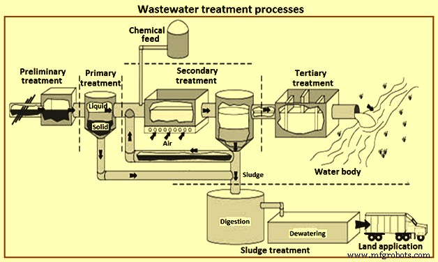
그림 1 폐수 처리 공정
예비 치료
예비 처리의 목적은 막힘, 다운스트림 장비 막힘 및 장비 마모를 유발할 수 있는 재료를 제거하는 것입니다. 예비 처리는 일반적으로 폐수가 ETP로 보내지기 전에 그리고 ETP의 성능을 개선하기 위해 수행됩니다. 이 처리에서 폐수에서 거친 고형물 및 기타 큰 물질이 제거됩니다. 이러한 물질의 제거는 후속 처리 장치의 운영 및 유지 관리 효율성을 향상시키는 데 필수적입니다. 이러한 폐수 처리에서는 폐수의 바람직하지 않은 특성을 제거하기 위해 여러 단위 공정이 사용됩니다. 여기에는 일반적으로 (i) 냄새 제어, (ii) 사전 통기, 거친 고체 연삭, 스크린 및 화격자 등을 사용한 큰 재료 제거와 같은 작업이 포함됩니다. 여러 번 오일과 그리스 및 pH 제거 수정도 수행됩니다.
일차 치료
폐수처리공정의 첫 번째 단계 또는 전처리 후의 두 번째 단계입니다. 1차 처리는 예비 처리를 따르고 알칼리 조건에서 중화에 가까운 pH로 pH를 수정하기 위한 물리적 및 화학적 처리와 하류 공정에서 BOD 및 SS 부하를 줄이기 위해 1차 정화기에서 부유 고체를 물리적으로 침전시키는 것을 포함합니다. 전반적으로, 1차 정화 장치의 채택은 다운스트림 생물학적 공정 운영에 대한 문제가 적다는 것을 나타냅니다. 예를 들어, 생물학적 반응기의 오일 및 그리스 및 바이오매스 축적량이 적어 탱크 내 침전 가능성을 최소화하고 활성 슬러지 바이오매스 등의 '비필라멘트형' 팽창 경향을 줄입니다. 대부분의 경우 1차 처리는 다음을 사용합니다. 응고 – 고형물 분리를 개선하기 위한 응집 과정입니다.
전반적으로 1차 정화 장치의 채택은 하류 생물학적 공정 운영에 대한 문제가 적다는 것을 나타냅니다. 1차 처리의 목적은 침전에 의한 침강성 유기 및 무기 고형물의 제거와 스키밍에 의한 부유 물질의 제거입니다. 1차 처리 동안 전체 내부 BOD의 약 35% ~ 55%, 전체 SS의 약 55% ~ 75%, 오일 및 그리스의 약 70%가 일반적으로 제거됩니다. 소량의 유기 인과 유기 질소 및 고형물과 관련된 중금속이 1차 침전 동안 제거되지만 콜로이드 및 용해된 성분은 영향을 받지 않습니다.
1차 처리 동안 1차 정화기를 사용하여 폐수에서 부유 물질을 물리적으로 분리합니다. TSS 및 관련 BOD 수준은 이 처리 과정에서 감소되고 폐기물은 폐수 처리의 다음 단계를 위해 준비됩니다. 침강 및 물질 스키밍에 의한 침강성 유기 및 무기 고형물의 제거가 이 처리 단계의 주요 목적입니다.
1차 처리는 다양한 물리화학적 공정을 포함하며 후속 처리 공정의 만족스러운 성능을 보장합니다. 1차 처리에 사용되는 주요 공정은 침전이고 사용되는 보조 공정은 미세 선별 및 응집 및 부유입니다. 응집은 일반적으로 석회, 명반 또는 독점 화학 물질을 사용한 화학 처리가 선행됩니다. 이 처리의 주요 목적은 침전에 의해 금속을 제거하고 일부 관련 콜로이드 BOD를 제거하여 화학 슬러지를 생성하는 것입니다. 1차 처리는 응고-응집 공정을 적용하여 고형물 분리를 개선합니다. 이러한 프로세스 중 일부는 아래에 설명되어 있습니다.
응집 – 물리적으로 혼합하고 화학적 응고제를 보조하여 점성 콜로이드 및 미묘하게 분리된 현탁물의 응집을 촉진하는 물리화학적 공정입니다. 이 공정은 급속 혼합 탱크와 응집 탱크로 구성됩니다. 폐수 흐름은 급속 혼합 탱크에서 응고제와 혼합된 다음 응집 대를 통과하고 응집 대에서 폐기물의 느린 혼합이 발생하여 입자가 더 침전되고 더 무거운 고체 형태로 수집되도록 합니다. 확산된 공기 또는 기계적 패들의 도움으로 더 나은 혼합이 촉진됩니다. 천연 유기 고분자, 무기 전해질 및 합성 고분자 전해질은 응고에 사용되는 다양한 유형의 화학 물질입니다. 오염물질의 특성과 화학적 성질에 따라 특정 화학물질이 선택됩니다.
침전 – 1차 침전의 주요 목적은 폐수에서 고상 및 액상 분획의 분리를 허용하는 것입니다. 중력을 사용하여 쉽게 침전되는 고형물을 제거합니다. 고형물은 주로 유기물이며 지방, 오일 및 그리스와 같은 부유 물질입니다. 침전된 고형물을 1차 슬러지라고 합니다. 따라서 이 공정은 유입 폐수의 SS 함량을 감소시킵니다. 1차 슬러지의 부피는 총 유입 폐수 부피의 약 2%에 불과하지만 수용된 유기물 부하(COD로 표시)의 약 30%~40%와 SS 부하의 약 40~60%를 구성합니다. 그리스와 부유 고형물을 제거하기 위한 배플과 오일 스키머가 침전 챔버에 포함되어 있으며 챔버 바닥에서 슬러지를 제거하기 위한 기계적 스크레이퍼가 있을 수도 있습니다.
고형물 제거 효율은 침전조 또는 정화조의 특성에 따라 다릅니다. 침전 탱크는 에너지 소산을 위한 입구 배플링, 미립자 침전을 위한 정지 구역, 침전된 고체 제거를 위한 기계적 수단, 출구로의 낮은 유속을 포함하는 장치입니다.
응집 및 침전 탱크는 직사각형, 원형 또는 경사 플레이트(라멜라)가 될 수 있으며, 선택은 현지 현장 조건, 사용 가능한 면적 및 설계 팀의 경험을 기반으로 합니다. 이상적으로는 두 개 이상의 탱크가 필요합니다. 직사각형 및 라멜라 탱크는 원형 탱크보다 적은 면적을 사용하며 토지 가용성이 낮은 곳에 유용합니다.
직사각형 탱크는 응집(화학적 보조 침전에서)을 증가시키고 체류 시간을 줄이기 위해 직선형 흐름 패턴을 가지고 있습니다. 물은 한쪽 끝에서 들어가고 입구 배플 장치를 통과하고 탱크의 길이를 가로질러 폐수 위어와 트로프까지 이동합니다. 길이:너비 비율이 3:1 ~ 5:1이 되도록 설계되어 이상적인 조건과 매우 유사한 넓은 유효 침하 구역과 1%의 바닥 경사를 제공합니다. 바닥에 있는 기계적 스크레이퍼는 침전된 슬러지를 수집 구역으로 모으는 것으로 이동합니다. 슬러지는 이후에 펌핑됩니다.
원형 정화기(그림 2)에서 흐름 패턴은 방사상입니다. 방사형 흐름 패턴을 달성하기 위해 대부분의 설계에서 폐수가 탱크 중앙 또는 때로는 주변 주위에 도입됩니다. 중앙 설계에서 폐수는 파이프와 '중앙 우물'로 알려진 중앙 배플을 통해 운반되고 탱크 둘레를 따라 흐르는 위어를 향해 방사상으로 흐릅니다. 중앙 유정의 직경은 일반적으로 전체 탱크 직경의 15%에서 25% 사이이고 높이는 1m에서 2.5m입니다. 정지 침강 구역은 이산 및 응집 침강을 위한 오버플로 속도 및 깊이 요구 사항을 충족하기에 충분히 커야 합니다.
처리된 물은 V자형 위어 플레이트를 통해 배출됩니다. 바닥은 슬러지 농축 및 제거를 돕기 위해 경사져 있습니다. 슬러지는 기계적 갈퀴를 사용하여 제거됩니다. 침전조의 일반적인 체류 시간은 2시간에서 3시간입니다. 부유 고형물 제거율은 45% ~ 55%입니다.
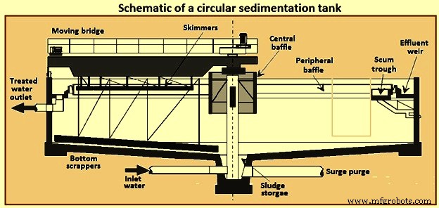
그림 2 원형 침전조 개략도
용해된 공기 부상 – 이 과정에서 기포를 사용합니다. 부유 입자를 쉽게 수집하고 제거할 수 있도록 폐수에 있는 부유 입자를 표면 수준까지 올리는 데 필요합니다. 폐수에 유입된 기포는 주로 부유하는 데 도움이 되는 입자에 부착됩니다. 유성 폐수 및 기타 폐수에서 나오는 부유 고형물, 분산된 오일 및 그리스는 DAF(용존 공기 부상) 공정으로 제거할 수 있습니다.
오일 및 그리스 제거를 위해 용해 공기 부상은 특히 부유 고체의 비중이 1.0에 가까운 경우에 적합합니다. DAF 공정은 압축 공기를 사용하여 입자에 부착되는 미세 기포(직경 10마이크로미터 ~ 50마이크로미터)를 방출하여 자유 오일 입자가 표면으로 올라간 다음 걷어내기 쉽습니다. DAF 공정은 비중이 물보다 작기 때문에 오일이 자연적으로 침강하지 않아 오일 및 그리스 제거에 매우 효과적입니다. 오일이 유화된 형태로 존재할 때 오일 에멀젼 층을 불안정하게 하기 위해 화학 물질이 필요합니다.
The pressurized water flow can be the entire inflow of wastewater, part of the inlet flow, or water already treated by the process (effluent). This results in dissolved air flotation to be three types of usable process, called full flow, partial flow or recirculated flow respectively. Fig 3 shows a schematic of the DAF process. The most common DAF application for wastewater treatment is a recirculated flow system, as it needs less equipment for pressurization (lower energy consumption), it avoids pump abrasion problems, and prevents the formation of colloids and emulsions within the pumping system.
DAF process can reduce oil concentrations to 10 mg/litre to 25 mg/litre as long as the influent concentration is not greater than 500 mg/litre. DAF process operates at higher hydraulic loading rates than gravity sedimentation systems and hence detention times are shorter by 15 minutes to 30 minutes. This allows the DAF process to be more compact and has a smaller footprint. DAF process systems are available in circular or rectangular configurations.
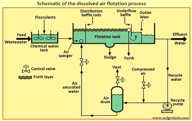
Fig 3 Schematic of the dissolved air flotation process
In retention tank the wastewater is pressurized and contacted with air. The super-saturated and pressurized water is passed through a pressure-reducing valve to the bottom of the floatation tank. The super-saturated air begins to come out in the form of fine bubbles from the solution, as and when the pressure starts releasing. The air bubbles attached with the suspended particles and trapped in sludge flock float over the surface and these floats are always swept from the surface and the mud is then collected from the bottom of the tank. The oil removal efficiency of the DAF process can be increased by the addition of certain coagulants.
Chemical treatment processes – The chemical treatment can be used, preferably before biological treatment as it removes the toxic chemicals which can kills the micro-organisms and or at any stage in the treatment process as and when it is necessary. Chemical treatment processes are described below.
Dissolved solids removal – Dissolved solids can be removed through a number of different methods namely (i) conversion to suspended materials, normally using chemicals to precipitate the contaminant as a solid or gas, to allow them to be removed by physical separation, (ii) adsorption onto a solid material, which can either be suspended or fixed as a bed, such as powdered or granular activated carbon, (iii) rejection using dense membrane processes, such as reverse osmosis or nano-filtration, or (iv) conversion to relatively innocuous end products.
Conversion necessarily involves chemistry or biochemistry, and the chemical reaction can be either reduction/oxidation (redox) or non-redox. Many chemical and biochemical processes operate by oxidation, the end products in the case of organic pollutants normally being carbon dioxide, nitrate and water. Examples of chemical reduction include the quenching of excess chlorine using bisulphite or the biochemical reduction of nitrate to nitrogen, the latter being referred to as ‘denitrification’. There also exist many important non-redox chemical processes, such as pH adjustment or precipitation of alkaline earth salts such as calcium carbonate or sulphate.
Neutralization – There is a wide range of pH of the untreated wastewater and it is not so easy to treat the wastewater with such type of varying range of the pH value. To optimize the treatment efficiency the neutralization process is used to adjust the pH value. To reduce the pH value sulphuric or hydrochloric acids can be added and to raise the pH value, dehydrated lime or sodium hydroxide alkalis can be added. Normally the process of neutralization is carried in a rapid mix holding tank or in a tank used for equalization. To control the pH of the discharge in order to meet the standards, the process of neutralization can be carried out at the end of the treatment.
Precipitation – The process of precipitation is carried out in two steps for the removal of the metal compounds from the stream of the wastewater. The mixing of precipitants with the wastewater and allowing a formation of the insoluble metal precipitants is the first step of the precipitation process. The removal of the precipitated metals from the wastewater through clarification and filtration is carried out in the second step and then the resulting sludge is being treated in a proper manner, and after treatment, it is recycled or disposed off. The important parameter to be considered in a chemical precipitation is pH controlling.
The solubility of metal hydroxides increases towards higher or lower pH and this is amphoteric in nature. Thus, for the precipitation of hydroxide for each metal, there is an optimum value of pH. As there is normally more than one metal in wastewater, hence, it is very much difficult to select the optimum treatment chemical and the pH control becomes more difficult and also it involves a transaction between the best possible removals of two or more metals. Lime, sodium hydroxide, soda ash, sodium sulphide and the ferrous sulphate are the various different chemicals used for the process of precipitation. The process for the effective removal of the metals like antimony, arsenic, chromium, copper, lead, nickel and zinc is normally the hydroxide precipitation and for removing mercury, lead, copper, silver, cadmium etc. sulphide precipitation is used. Fig 4 shows flow diagram of chemical treatment process for metal removal.
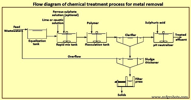
Fig 4 Flow diagram of chemical treatment process for metal removal
Secondary treatment
The secondary treatment process involves disintegration or decomposition of the suspended and dissolved organic substances present in the waste water using microorganisms. The activated sludge process (ASP) and the biological filtration methods are the mainly used biological treatment processes. The biological treatment process which is the mainly used for the secondary treatment process is based on the micro-biological action to decay the organic suspended and dissolved wastewater. The microbes can be used for the natural compound, both as a source of carbon sources and as an energy sources.
For removal of organic pollutants, the most efficient secondary treatment process is biological treatment. It primarily employs microbes naturally present in wastewater to break down organic contaminants. Some inorganic compounds like ammonia, cyanide, sulphide, sulphate and thio-cyanate are also biologically degradable. Biological processes can be broadly classified as (i) aerobic in which microbes which are used need oxygen to grow, (ii) anaerobic in which microbes which are used grow in the absence of oxygen but uses other compounds such as sulphate, phosphate or other organics present in the wastewater other than oxygen, and (iii) facultative in which microbes which are used can grow in the presence or absence of oxygen.
Aerobic processes consist of a biological reactor with a controlled amount of biomass and a clarifier for separation of the biomass from the final effluent. Aerobic processes need higher energy inputs and produce greater amounts of sludge compared to anaerobic systems. As an example, for the same 100 kg COD load entering the aerobic treatment plant, the energy needed is 100 kWh for aeration and produces 30 kg to 60 kg of sludge with the outlet effluent COD load of 2 kg to 10 kg. In the anaerobic treatment plant for the same 100 kg COD load, the sludge production is only 5 kg, or six to twelve times less, and produces 40 cum (cubic meter) to 45 cum of biogas which can be converted to produce 382 kWh of electricity. However, the outlet water COD is twice that of the aerobic plant, and hence of a lower quality.
Hydraulic retention time – It is the average time in the aeration basin equivalent to the volume of the basin divided by the average flow and expressed as hours. The hydraulic retention time is required to be sufficiently long to remove the prerequisite BOD and is dependent on the type of the biological treatment system. It can range from 0.5 hours to 120 hours. The lower the hydraulic retention time the quicker the wastewater reaches the outlet.
Mixed liquor suspended solids (MLSS) – Suspended solids level is one of the most important control parameters in biological wastewater treatment processes. It is not only directly related to sludge settling properties and effluent quality, but also related to food / micro-organism ratio which is in turn related with all aspects of sludge properties. MLSS represents the total suspended solids including bacteria, dead biomass, and higher life forms, irrespective of biological activity. The organic portion of MLSS is represented by ‘mixed liquor volatile suspended solids’ (MLVSS) which represents the biomass. MLSS is controlled by the sludge wasting rate. Typical MLSS are dependent on the process type. The more concentrated is the MLSS, the smaller is the equipment footprint and hence the popularity of membrane bioreactors (MBRs) in space constrained locations. MLVSS is 0.75 MLSS.
Food to microorganism (F/M) ratio – It is a term used for expressing the organic loading of an activated sludge process. F/M is a critical factor in process design and operation, especially in determining the aeration basin volume. F/M range is around 0.5 to 1.5. For conventional plants, F/M of 0.2 to 0.5 is aimed for. In biological treatment plants operating at high F/M loads (0.8 to 1.5), the rate of treatment increases at the cost of poor settlability of the sludge. Processes operating at low F/M loads (0.05 to 0.2) are associated with slow BOD removal rates but with good sludge settling. However, the system can be easily upset by a spike load of organics.
Sludge age – It is also known as ‘mean cell residence time’ (MCRT) and ‘solids retention time’ (SRT). It is calculated as the total quantity of sludge in the aeration tank and clarifier divided by the daily sludge losses through waste activated sludge and effluent. Sludge age can vary from 0.5 day to 75 days in low-growth rate systems. Sludge age is an indication of F/M ratios. Shorter times are indicative of high F/M ratios and longer times are indicative of low F/M ratios. Sludge age is expressed by the equation ‘sludge age =sludge mass in (aeration tank + clarifier) / daily sludge losses’.
The quality of sludge age can be determined using a microscope at 100x magnification. Daily microscopic analysis can prevent problems. Micro-organisms considered important in biological treatment are bacteria, fungi, algae, protozoa, rotifers, and worms. The presence of higher life form indicator organisms normally correlates to plant performance. They can indicate if the sludge is young, medium, or old. Good settling sludge is characterized by the presence of protozoa such as stalked ciliates and suctorians and normally is golden brown in colour (sewage treatment plants). Low sludge age is characterized by the absence of stalked ciliates and predominance of free swimming ciliates such as paramecium (these expend a lot of energy in swimming) and high BOD slugs by the absence of higher life forms. Old sludge is characterized by the presence of many worms (nematodes) or rotifers.
Another useful indicator is the ‘sludge volume index’ (SVI). Sludge is poured to a 1 litre graduated cylinder and the percentage of settled sludge in 5 minute intervals is noted for 30 minutes. SVI is expressed in ml/g. It is a reliable troubleshooting test. SVI values can vary from 30 ml/g to 400 ml/g. Values below 150 indicate good sludge settling and above this indicate sludge bulking. Other key variables which affect the operation of the biological reactor are given below.
Oxygen requirement – Oxygen is needed for the decomposition of organic matter. The concentration depends on organic matter consumption, endogenous respiration demand and total nitrification of TKN (total Kjeldahl nitrogen) oxidation. Typical oxygen concentration in an aeration tank is 2 mg/l to 4 mg/l. The higher values are maintained for nitrogen removal. Above this, electricity is wasted.
Sludge production (sludge yield) – The decay of biomass produces sludge. For conventional industrial systems, sludge production can be as low as 0.15 kg / kg BOD, such as in coke making.
Sludge recirculation rate – A portion of the sludge produced is recirculated to promote the production of more sludge in the aeration tank. It is the ratio between the sludge recirculation volumetric flow and treatment volumetric inflow. In any case, the capacity of the sludge recirculation system is not to be less than 200 % of the daily average total inflow.
Nutrient requirements (C:N:P ratio) – Besides carbon, hydrogen, and oxygen biomass needs nitrogen, phosphorous, and micro-nutrients such as iron, calcium, magnesium, copper, zinc and so on. Most industrial wastewaters lack N and P which is to be added (in the form of urea, super-phosphate or ammonium phosphate) to maintain optimal microbial growth conditions. The minimum C:N:P ratio needed for optimal microbial growth in the in aerobic processes is 100:5:1, and anaerobic processes is 330:5:1.
The most common biological processes are described briefly below.
Aerobic processes – activated sludge process – Biological processes, employing aerobic biomass in suspension, have traditionally been known as activated sludge processes. The ASP was developed in the United Kingdom in the early 1900s for the treatment of the domestic sewage and it has since been adapted for removing biodegradable organics in industrial wastewater. The ASP and its variants are capable of treating biodegradable wastewater of moderate strength (10 mg/l to 1,000 mg/l BOD) to high strength (greater than 1,000 mg/l BOD). The ASP does not remove heavy metals or TDS. Some contaminants such as cyanide, and heavy metals such as chromium and mercury, present in the wastewater act as inhibitors for the proper functioning of the ASP as well as other biological processes. ASPs have been categorized, according to the mass loading design, in three groups namely (i) low load activated sludge (extended aeration, oxidation ditches, etc.), (ii) medium load (or conventional), and (iii) high loading.
The ASP involves blending settled primary wastewater or equalized influent with a culture of micro-organisms into a fluid called ‘mixed liquor’. This mixed liquor is passed through an aeration tank which provides an adequate oxygen rich environment for the microbes to eat and stabilize the organic matter in water. Mixing brings oxygen and food to micro-organisms allowing the micro-organisms to clump together whilst preventing floc settling in the aeration tank. The process produces ‘waste activated sludge’ (WAS) consisting of microbes and excess microbial matter. The solids and treated wastewater are separated in a secondary clarifier or other solids separation step such as a membrane bioreactor (MBR). Here the majority of the WAS is returned to the aeration tank as returned activated sludge (RAS) to maintain the microbial population in the aeration tank, as well as ensuring that the activated sludge is old enough to degrade COD and aromatic hydrocarbons. The remainder is removed and undergoes thickening.
The secondary clarifier has the dual purpose of clarifying the wastewater as well as concentrating the sludge. The process is sensitive to pH fluctuations, where a high or low pH can upset the system and cause overloading of the clarifier. Fig 5 shows a schematic of the activated sludge process and membrane bioreactor process.
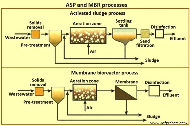
Fig 5 ASP and MBR processes
Nitrogen containing compounds are toxic to aquatic life, deplete oxygen in the receiving waters, adversely affect public health and reduce the potential for water reuse. Hence, nitrogen containing compounds are removed, if deemed excessive, by nitrification and then denitrification processes. Organic nitrogen is converted to ammonia, then converted to nitrite, which is further oxidized to nitrate and finally to gaseous nitrogen. Denitrification consumes alkalinity and needs to be sufficient so as not to depress the pH. It requires 7.14 mg/l of bicarbonate alkalinity for each 1 mg/l of ammonia nitrogen removed. Oxygen also needs to be maintained at concentrations closer to 4 mg/l for denitrification. The process control is normally customized for each effluent treatment system depending on wastewater characteristics and for optimal operation.
Aerobic processes – oxidation ditch process – This process which has been developed in the 1950s in the Netherlands, is a variant of the ASP and is a special form of extended aeration. The shape of the oxidation ditch is like a ring. Wastewater, micro-organisms and activated sludge is mixed in a continuous loop ditch in order to complete nitrification and denitrification reactions. The oxidation equipment consists of ditch body, aeration mixers and inlet and outlets. Given its long hydraulic retention time of 20 hours to 36 hours, low organic loading and long sludge age compared to conventional ASP, equalization, primary sedimentation, and sludge digestion tanks are omitted.
Oxidation ditch has many advantages in that it provides (i) low energy consumption, (ii) low maintenance, (iii) ease of operation, low capital expenditure, (iv) less sludge due to long extended solids retention time, and (v) resistance to shock loads and hydraulic surges due to long hydraulic retention time. The disadvantages are that the effluent suspended solid quality is inferior to the ASP process and needs a large land area.
Aerobic processes – sequencing batch reactor – The sequencing batch reactor (SBR) process differs from the other ASPs. It is a batch process. The principle is that all of the process steps of ASP, i.e. primary settling, biological oxidation and secondary settling take place in a single tank. The process steps are filling, react, settle, draw, and idle. SBR is compact and has low capital expenditure. It is used when land area is scarce since it needs only one tank to fulfill the aeration and clarification steps. It is also used to treat nitrogen and phosphorous. Standard cycles are normally 4 hour to 6 hours long, resulting in 4 to 6 reaction cycles per day. Compared to the conventional ASP, it is resistant to shock loading, flexible operation due to adjustment of run time and low sludge production.
Trickling filters – These filters, developed in the 1890s, are an example of a fixed film biological process compared to the ASP which is a suspended process. A trickling filter consists of bed of coarse material, such as rounded rocks (25 mm to 100 mm in diameter), crushed stone, wooden or plastic slats and plastic rings over which wastewater is discharged from moving spray distributors or fixed nozzles. The filter media provides a large amount of surface area for the micro-organisms to cling and grow a jelly like bio-film of around 10 mm thickness. In the outer portions of the bio-film (0.1 mm to 0.2 mm) the aerobic bacteria break down the organic matter. When the bio-film becomes very thick it falls off and a new bio-film layer forms. Modern trickling filters use plastic media over rocks since they weigh less and because of it, filter media can be upto 6 m in depth compared to 3 m in depth for rock filters, allowing taller filters using less land area.
The filter effluent is recycled to minimize drying of the filter media, improve filter efficiency, and reduce odour potential. Sometimes, two filters are assembled in series to handle strong wastewater. The sprays rotate at 2 revolutions per minute (rpm) to 5 rpm and a typical wetting rate is 0.6 cum/hour to 2.4 cum /hour. When the wetting rate is too low, the water does not penetrate the depth of the filter bed uniformly causing channeling and acts as an incubator for flies, as well as creating odour problems. Low rate filters operate on natural ventilation, whereas high rate filters require forced draft fans to provide adequate ventilation.
The trickling filter is followed by a secondary clarifier. Trickling filters are classified according to the organic and hydraulic loads such as low rate, intermediate, high rate, roughing filter and super high rate. The advantages of a trickling filter are (i) lower energy requirements than ASPs, (ii) simple operation with no issues of MLSS inventory control and sludge wasting, (iii) better recovery from shock toxic loads, (iv) no problems of bulking sludge in secondary clarifiers, (v) compact and suitable for place where land is scarce, (vi) less equipment maintenance needs, effective in treating high concentration of organics dependent on type of media used, and (vii) better sludge thickening properties. The disadvantages are organic loading levels, that the effluent water quality (in terms of BOD and TSS) is lower than ASP and can need further treatment, odour problems, flies, prone to plugging of filter media and at low temperatures natural ventilation systems do not operate that well.
Moving bed bioreactor – Moving bed bioreactor (MBBR) was developed in the 1980s by Kaldnes in Scandinavia. The MBBR process is a more modern fixed film process in which the micro-organisms grow on plastic media. The media are made from high density polyethylene or polypropylene with a diameter of 13 mm to 25 mm, and hence have a large surface area which helps the biomass to grow inside the surface and are in constant motion due to the compressed air which is blown from under the tank. The process has been applied in a variety of industrial wastewater treatment applications in aerobic and anaerobic modes with or without denitrification depending on the mode of mixing.
Benefits of MBBR are that it is good for high organic loading applications, improved settling characteristics, no need for sludge recirculation from secondary clarifier thereby making it a ‘once through’ process, compact and low footprint compared to the ASP process and has modular construction. It can also retrofit existing ASP systems, needs fewer operational controls than ASPs, and contains fewer mechanical and instrumentation controls compared to a MBR system. A typical hydraulic retention time for MBBR is 2 hours to 3 hours, compared to 12 hours to 24 hours for ASPs. Disadvantages of MBBRs compared to the ASP are that it needs a higher oxygen concentration, the need for improved influent wastewater screening, and additional hydraulic profile head losses due to flow through the media screening devices.
Membrane bioreactor – Though external membrane bioreactors were originally developed in the 1960s, they became popular only after the development of the immersed (submerged) MBRs in the late 1980s. The lower operating cost of the submerged MBR configuration and the decreasing cost of the membranes have made MBRs a popular choice for domestic and industrial wastewater treatment. MBRs are used for industrial wastes with BOD of 5,000 mg/l to 40,000 mg/l with BOD ranges of 200 mg/l to 600 mg/l. Fig 6 shows the principle of membrane bioreactor.
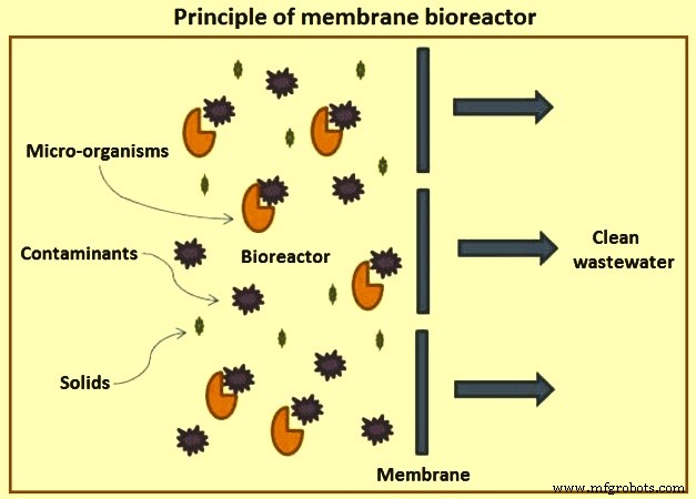
Fig 6 Principle of membrane bioreactor
The quality of the final effluent from a conventional ASP unit is highly dependent on the hydrodynamic conditions in the clarifier and settling characteristics of the sludge. This leads to variable performance. As a result, large clarifiers are needed with long residence times. The MBR process was developed to remove these disadvantages of conventional ASPs.
MBRs are a hybrid with two interdependent treatment processes:biological treatment and membrane treatment (Fig 5). It is similar to a conventional ASP in that both have mixed liquor solids in suspension in an aeration tank. The difference in the two processes lies in the method of separation of bio-solids. In the MBR process, the membranes create a solid barrier to bio-solids based on micro-filtration (MF) with a pore size of 0.6 micrometers, or ultra-filtration with a pore size of 0. 04 micrometers, and hence are not subject to gravity settling characteristics of the solids. Thus, a MBR unit brings aeration, clarification, and filtration in a single step with MLSS concentrations reaching 20,000 mg/l or higher resulting in a smaller footprint than conventional ASP units.
MBRs provide a final effluent quality independent of sludge conditions with higher removal of organics and persistent pollutants, and nutrients with COD removal of 98 % and suspended solids removal efficiency of 100 %. The high quality effluent produced is ideal for reuse applications. Another feature of MBRs is the long sludge age. However, this also contributes to fouling of membranes. Moreover, MBR units can be installed directly to a reverse osmosis (RO) plant, bypassing the need for an ion exchange or other equipment to protect a membrane plant provided the hardness or scaling compounds are not excessive.
There are two types of MBR configurations namely immersed and side-stream. Immersed systems are more common in large industrial units, whereas side-stream is limited to smaller units. There are also differences in the membrane employed from hollow fibre, flat plate, and tubular. Immersed MBRs use hollow fibre or flat plate whereas tubular membranes are used in side-stream MBRs. MBR produces an equivalent treatment level to an activated sludge process followed by micro-filtration or ultra-filtration.
Despite the advantages of MBRs, there are still challenges in using MBRs in industrial applications. The advantages of MBR are (i) 25 % lower footprint, (ii) replaces the clarifier and gravity filter of conventional systems, (iii) ideal for land constrained sites and lower hydraulic retention time of 4 hours to 8 hours. MBR provides impermeable barrier for solids producing highest quality effluent with BOD less than 5 mg/l and turbidity of less than 0.1 NTU (Nephelometric turbidity unit). Membrane fouling is one of the major challenges which results in reduced performance and frequent cleaning or membrane replacement leading to increased maintenance and operating costs. All MBRs require a minimum of fine screens of 3 mm. Sludge produced can be difficult to dewater. Sludge retention time is independent of hydraulic retention time. High sludge age of 15 days to 140 days can be obtained. It has modular expandability, less odour, and flexible operation with less susceptible to upsets. The process can be automated.
Secondary clarifiers – The purpose of the clarifier is twofold. One is to thicken the solids after biological treatment and then settle them out. The second is to produce a clear effluent of the settled solids. Clarifiers in activated sludge systems are to be designed not only for hydraulic overflow rates, but also for solids loading rates. This is because both clarification and thickening are needed in activated sludge clarifiers. Of the process variables the most important is sludge age or mean cell residence time. Another important control parameter is the solids loading rate which is defined as the required surface for suitable sludge thickening in the bottom of the unit (compression zone). The clarifiers are either of rectangular design or of circular design.
Tertiary treatment
Conventional secondary treatment frequently is not sufficient to meet the required effluent quality standards to discharge water to surface water bodies. The effluents can need tertiary processes so as to complete solids and organic matter removal, for colour reduction or recalcitrant compounds degradation, nutrient reduction, and disinfection. The persistent contaminants which the secondary treatment is not able to remove are removed by the tertiary treatment process. These processes are classified as ‘tertiary treatments’, as they are installed after secondary treatment, but some of them, like oxidation processes, can be also placed before biological treatment to improve the bio-degradability of recalcitrant compounds.
Before the treated wastewater is reused, recycled, or discharged to the environment, the tertiary treatment process is used as a final cleaning process cleaning process to improve the quality of the wastewater. For the removal of nutrient (nitrogen and phosphorus), removal of toxin [pesticides, VOC &metals], and for the polishing of the effluent like BOD &TSS, the tertiary treatment processes are used. These processes are the extension of conventional secondary biological treatment process for the further stabilization of the substances which demands oxygen in the wastewater, and also to remove the nitrogen and phosphorus.
The physical and chemical separation techniques like activated carbon adsorption, flocculation or precipitation are the process involved in the tertiary treatments. The most common tertiary treatment applications are filtration and disinfection and where applicable ammonia and phosphorous removal. Ammonia is toxic to fish and phosphorous causes algal blooms.
Filtration – Filtration is a separation process which consists in passing a solid–liquid mixture through a porous material (filter media) which retains the solids and allows the liquid filtrate to pass through. Granular media polishing filters are used the removal of suspended solids for the removal of suspended solids in the 5 mg/l to 50 mg/L range. The most common filters are the multimedia filters. The quality of the filtrate depends on the size, surface charge, and geometry of both suspended solids and filter media, as well as on the water analysis and operational parameters. Based on media filters can be categorized as (i) single media (sand or anthracite), (ii) dual media (sand and anthracite), and (iii) multimedia (garnet, sand, and anthracite).
The most common filter media in water treatment are sand and anthracite. The effective grain size for fine sand filter is in the range of 0.35 mm to 0.5 mm, and 0.7 mm to 0.8 mm for anthracite filter. In comparison to single sand filter media, dual filter media with anthracite over sand permit more penetration of the suspended matter into the filter bed, thus resulting in more efficient filtration and longer runs between cleaning. The design depth of the filter media is a minimum of 0.8 m. In the dual filter media, the filters are normally filled with 0.5 m of sand covered with 0.3 m of anthracite.
In industrial applications, filters are housed in steel pressure vessels where the interior is epoxy coated, with interior manifolds for distribution of water and an under drain system for collection of filtrate and backwashing.
As the filter vessel for pressure filtration is designed for pressurization, a higher-pressure drop can be applied for higher filter beds and / or smaller filter grains and / or higher filtration velocities. The design filtration flow rates are normally 10 m/h to 20 m/h and the backwash rates are in the range of 40 m/h to 50 m/h. The available pressure is normally about 2 bars to more than 4 bars.
For feed waters with a high fouling potential, flow rates of less than 10 m/h and / or second pass media filtration are preferred. If the flow rate has to be increased to compensate for one filter which goes out of service, the flow rate increase is to be gradual and slow to prevent the release of previously deposited particles.
During operation, influent water to be filtered enters at the top of the filter, percolates through the filter bed, and is drawn off through the collector system at the bottom. Periodically, when the differential pressure increase between the inlet and outlet of the pressure filter is 0.3 bars to 0.6 bars, the filter is backwashed and rinsed to carry away the deposited matter. Backwash time is normally about 10 minutes. Before a backwashed filter is placed back into service, it is to be rinsed to drain until the filtrate meets the specification. Backwash rates when excessive leads to loss of filter media.
Variations of the deep rate filtration are high rate filtration which operates at much faster inlet flow rates. Aside from media filters, other types of filters are disc filters and cartridge filters. These are also used to protect membrane filtration systems. Disc filters made from pleated cloth media have very high flow rates and a small footprint, producing very high quality water suitable for reuse applications and do not need extensive backwashing.
Some advanced water treatment processes are also used as the tertiary treatment. These processes are applied to the conventional treated wastewater to improve the quality upto a degree suitable for various applications of recycle and reuse including the potable reuse. The additional tertiary treatment processes are different membrane treatment processes like micro-filtration, ultra filtration, nano-filtration, other processes like reverse osmosis, advanced oxidation processes, and additional disinfection processes like ozonation and the use of ultraviolet radiation. Some of these advanced processes are described below.
Membrane technology – Membranes are a popular choice for water reuse applications since their advent in the 1960s. Costs of membrane systems have reduced dramatically and, coupled with technological advances in membrane design, membrane options and operating limits, the range of applications in water and wastewater treatment is increasing rapidly. In pressure driven membrane filtration, membranes separate the components of a fluid under pressure. The membrane pores, being extremely small, allow the selective passage of solutes. The popularity of membrane processes arises from the fact that they are effective in the removal of both dissolved and suspended solids. A wide range of materials like cellulose acetate, polyamides, poly- sulfones, poly-propylene, nylon, poly-acrylonitrile, poly-carbonate, polyvinyl alcohol, poly-tetra-fluoro-ethylene, ceramic, and metal composites are basically used to produce the membranes. The membrane pore size is the parameter for the degree of selectivity of a membrane. On the basis of the pore size, there are four types of pressure driven membranes. Micro-filtration and ultra-filtration are low pressure applications given their larger pore size. Nano-filtration needs medium pressure, and ‘reverse osmosis, given the smaller pore size, needs significant pressure to push the solute through the membrane.
Advanced oxidation processes – Advanced oxidation processes (AOPs) are defined as processes which involve generation and use of powerful but relatively non-selective hydroxyl radicals in sufficient quantities to be able to oxidize the majority of the complex chemicals present in the effluent water. The AOPs show specific advantages over conventional treatment alternatives since they can eliminate non-biodegradable organic components and avoid the need to dispose of residual sludge. After fluorine ([V (volts) =-3.06], hydroxyl free radicals (OH-) have the highest oxidation potential (V =-2.86). In the AOP process, OH – radicals are generated which in turn react with organic molecules to generate CO2 and water. AOPs can be classified into two groups, non-photochemical AOPs and photochemical AOPs. Photochemical means a light source is needed. Normally ultra violet (UV) light is used as the photo-chemical source. Low pressure UV lamps have a wavelength of 254 nm. Maximum ozone absorption takes place at a wavelength of 253.7 nm. Of the non-photo-chemical technologies, those most prevalent in the treatment are Ozonation, Ozone/ (H2O2) and Fenton’s reaction.
Ozonation – Discovered in 1785, Ozone (O3) is a widely applied strong oxidizing agent (-2.07V) for disinfection of potable water and wastewater, decolourization, odour removal, organics degradation and cyanide destruction, etc. O3 at room temperature is a bluish pungent gas, sparingly soluble in water, highly corrosive, toxic and explosive when the concentrations in air exceed 20 %. As a germicide, it is 3,125 times faster than chlorine. Ozonation efficacy is increased with high pH and temperature. When O3 dissolves in water or wastewater it can remain as the O3 molecule (at pH more than 7 and slower reaction) or decompose (pH more than 8) producing the hydroxyl free radical (OH-) which is a 35 % stronger oxidizing agent than O3. Both reactions occur simultaneously and hence reaction kinetics strongly depends on the characteristics of the treated wastewater (e.g. pH, organic concentrations, presence of foaming agents and surfactants, ozone concentration and temperature, etc.). A pH of 8 to 10 is most suitable for oxidation of organic compounds. Ozone is sparingly soluble in water and rapidly decreases with increasing temperature. At a temperature of 20 deg C, 100 % ozone solubility in water is 570 mg/l. The preferred temperature ranges from 25 deg C to 50 deg C.
A simplified reaction mechanism of ozone at a high pH is given by the equation 3 O3 + H2O =2OH radical + 4 O2. Molecular O3 is a very selective oxidant. It only reacts with certain compounds and for this reason it can be applied in low dosages for industrial wastewater applications. It can also inhibit or destroy the foaming properties of residual surfactants as well as oxidizing a good portion of the COD. Thus, O3 improves the overall biodegradability of the effluent by converting recalcitrant compounds to easily digestible compounds and can be applied upstream or downstream of a biological treatment plant. The residual oxygen in the vent gas can be recycled back to the secondary biological treatment plant, reducing aeration requirements. Another advantage is that it does not increase sludge mass.
O3 can be applied in the gaseous form and because of its unstable nature it needs to be generated on-site from air or pure oxygen using UV radiation, electrochemistry or corona discharge generators. O3 leak detectors are to be installed to give audible and visible warnings and shut down the generators in the event of a leak. O3 is deactivated in the presence of high concentration of salts. A variation of this process is the O3/H2O2 process. Developed to reduce the O3 concentrations, the H2O2 acts as a catalyst enhancing the capability of O3 to produce more OH radicals. At a low pH, H2O2 reacts very slowly with O3 and at a high pH (alkaline conditions) reacts rapidly.
제조공정
항공우주 및 항공 회사는 장비 및 구성 요소에 대한 고유한 문제에 직면해 있습니다. 첫째, 기능을 안정적이고 효율적으로 수행하는 매우 복잡하고 정밀한 부품이 필요합니다. 또한 이러한 구성 요소는 성능에 영향을 줄 수 있는 극심한 환경 스트레스를 경험할 수 있습니다. 극한의 온도 차이에서 부식성 요소에 이르기까지 구성 요소는 이러한 응력을 견디고 중요한 기능을 수행할 때 부품 고장을 유발할 수 있는 부식 및 마모에 저항하도록 설계되어야 합니다. 정밀 주조 및 표면 처리 솔루션은 항공우주 주조에서 중요한 역할을 합니다. 이러한 기술은
SKD11 다이스틸은 일본의 공구강입니다. 재료 열처리 경도:hrc58-60 SKD11은 일종의 고탄소 및 고크롬 합금 공구강입니다. 열처리 후 높은 경도, 연삭성, 강한 경화성 및 우수한 치수 안정성을 갖습니다. 좋은 기계 가공성, 미세하고 균일한 탄화물 입자, 화학 원소인 몰리브덴과 바나듐의 특수 첨가로 인해 담금질 균열에 대해 걱정할 필요가 없습니다. SKD11 특정 성능 A) 고온 강도 및 인성, 우수한 내마모성, 쉬운 절단; B) 강도, 인성 및 내열성 균형이 우수한 냉간 가공 다이 강, 다) 진공 탈기 정제를