

verilog

산업 제조
이전 기사에서 보았듯이 더 크고 복잡한 디자인은 계층적 방식으로 여러 모듈을 통합하여 구축됩니다. 모듈은 인스턴스화할 수 있습니다. 이러한 인스턴스의 다른 모듈 및 포트 내 상위 모듈 내부의 다른 신호와 연결할 수 있습니다.
이러한 포트 연결은 정렬된 목록이나 이름으로 수행할 수 있습니다.
모듈 인스턴스화에 나열된 포트 표현식과 상위 모듈 내부의 신호를 연결하는 한 가지 방법은 순서 목록을 사용하는 것입니다. .
mydesign은 module입니다. tb_top이라는 다른 모듈에서 d0이라는 이름으로 인스턴스화됩니다. 포트는 모듈 선언의 포트 목록에서 해당 포트의 위치에 따라 결정되는 특정 순서로 연결됩니다. 예를 들어, 테스트벤치의 b는 디자인의 y에 연결됩니다. 둘 다 포트 목록의 두 번째 위치에 있기 때문입니다.
	module mydesign ( input  x, y, z,     // x is at position 1, y at 2, x at 3 and
	                  output o);          // o is at position 4

	endmodule

	module tb_top;
		wire [1:0]  a;
		wire        b, c;

		mydesign d0  (a[0], b, a[1], c);  // a[0] is at position 1 so it is automatically connected to x
		                                  // b is at position 2 so it is automatically connected to y
		                                  // a[1] is at position 3 so it is connected to z
		                                  // c is at position 4, and hence connection is with o
	endmodule
올바른 연결을 위해 설계 모듈의 포트 순서를 알아야 합니다.
새로운 포트가 목록에 추가되거나 디자인에 있는 포트의 수가 매우 많을 경우 순서가 변경될 수 있기 때문에 매우 불편합니다.
포트를 연결하는 더 좋은 방법은 포트 이름을 사용하여 양쪽에 있는 포트를 명시적으로 연결하는 것입니다. .
점 . 점 뒤에 오는 포트 이름이 디자인에 속해 있음을 나타냅니다. 디자인 포트가 연결되어야 하는 신호 이름은 ( ) 괄호 안에 다음으로 주어집니다. .
module design_top;
	wire [1:0]  a;
	wire        b, c;

	mydesign d0  ( .x (a[0]),    // signal "x" in mydesign should be connected to "a[0]" in this module (design_top)
	               .y (b),       // signal "y" in mydesign should be connected to "b" in this module (design_top)
	               .z (a[1]),
	               .o (c));
endmodule
컴파일 오류 메시지가 오류가 발생한 줄 번호를 올바르게 가리키도록 별도의 줄에 각 포트 연결을 코딩하는 것이 좋습니다. 이것은 모두 같은 줄에 있었다면 오류를 생성한 포트를 모르는 것과 비교하여 디버그하고 해결하기가 훨씬 쉽습니다.
이러한 연결은 이름으로 이루어지기 때문에 나타나는 순서는 중요하지 않습니다. 다중 모듈 인스턴스 포트 연결은 허용되지 않습니다.
	module design_top;
		mydesign d0 ( .x (a[0]),
		              .z (a[1]),     // z at second position is okay because of explicit connection
		              .y (a[1]),
		              .x (b),        // illegal - x is already connected to a[0]
		              .o (c));
	endmodule
인스턴스화 모듈의 와이어에 연결되지 않은 포트는 높은 임피던스 값을 갖습니다.
module design_top;
	mydesign d0   (              // x is an input and not connected, hence a[0] will be Z
	              .y (a[1]),
	              .z (a[1]),
	              .o ());        // o has valid value in mydesign but since
	                             // it is not connected to "c" in design_top, c will be Z
endmodule
이전에 본 시프트 레지스터의 예를 살펴보고 일부 포트는 연결되지 않은 상태로 둡니다.
module shift_reg (   input   d,
                    input    clk,
                    input   rstn,
                    output   q);

  wire [2:0] q_net;

  dff u0 (.d(d),         .clk(clk), .rstn(rstn), .q(q_net[0]));
  dff u1 (.d(q_net[0]), .clk(clk), .rstn(rstn), .q()); 						// Output q is left floating
  dff u2 (.d(q_net[1]), .clk(clk), .rstn(rstn), .q()); 						// Output q is left floating
  dff u3 (.d(q_net[2]), .clk(clk), .rstn(rstn), .q(q));

endmodule
인스턴스 u1 및 u2의 출력은 합성 후 얻은 RTL 회로도에서 연결되지 않은 상태로 유지됩니다. 인스턴스 u2 및 u3에 대한 입력 d는 이제 어떤 것으로도 구동되지 않는 네트에 연결되어 있으므로 접지됩니다.
<노스크립트>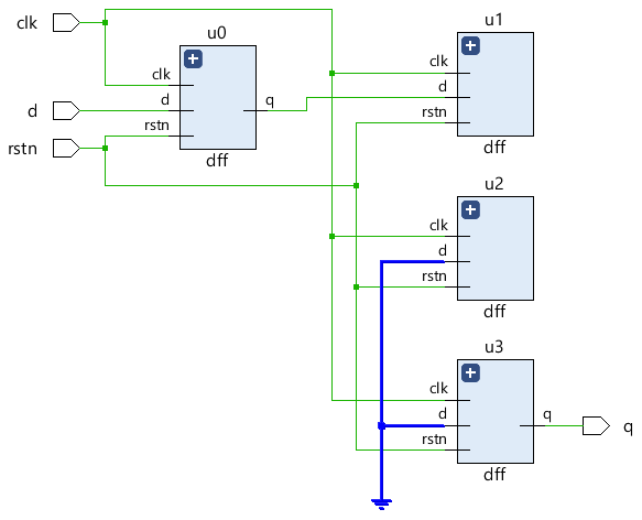
시뮬레이션에서 이러한 연결되지 않은 포트는 일반적으로 중간에 수직으로 정렬된 주황색 선으로 파형에 표시되는 고임피던스('hZ)로 표시됩니다.
<노스크립트>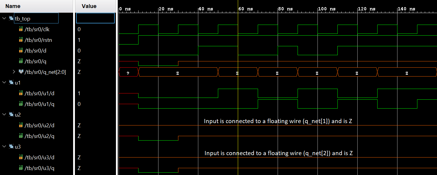
모든 포트 선언은 암시적으로 wire로 선언됩니다. 따라서 포트 방향은 이 경우 충분합니다. 그러나 output 값을 저장해야 하는 포트는 reg으로 선언되어야 합니다. 데이터 유형이며 always과 같은 절차 블록에서 사용할 수 있습니다. 및 initial 만.
input 유형의 포트 또는 inout reg으로 선언할 수 없습니다. 외부에서 지속적으로 구동되기 때문에 값을 저장하지 말고 외부 신호의 변화를 최대한 빨리 반영해야 합니다. 벡터 크기가 다른 두 포트를 연결하는 것은 완전히 합법적이지만 벡터 크기가 더 작은 포트가 우선하고 너비가 더 큰 다른 포트의 나머지 비트는 무시됩니다.
	// Case #1 : Inputs are by default implicitly declared as type "wire"
	module des0_1	(input wire clk ...); 		// wire need not be specified here
	module des0_2 	(input clk, ...); 			// By default clk is of type wire

	// Case #2 : Inputs cannot be of type reg
	module des1 (input reg clk, ...); 		// Illegal: inputs cannot be of type reg

	// Case #3: Take two modules here with varying port widths
	module des2 (output [3:0] data, ...);	// A module declaration with 4-bit vector as output
	module des3 (input [7:0] data, ...); 	// A module declaration with 8-bit vector as input

	module top ( ... );
		wire [7:0] net;
		des2  u0 ( .data(net) ... ); 		// Upper 4-bits of net are undriven
		des3  u1 ( .data(net) ... );
	endmodule

	// Case #4 : Outputs cannot be connected to reg in parent module
	module top_0 ( ... );
		reg [3:0] data_reg;

		des2 ( .data(data) ...); 	// Illegal: data output port is connected to a reg type signal "data_reg"
	endmodule
verilog
매개변수는 다른 사양으로 모듈을 재사용할 수 있도록 하는 Verilog 구성입니다. 예를 들어, 4비트 가산기는 비트 수에 대한 값을 허용하도록 매개변수화될 수 있으며 모듈 인스턴스화 중에 새 매개변수 값이 전달될 수 있습니다. 따라서 N비트 가산기는 4비트, 8비트 또는 16비트 가산기가 될 수 있습니다. 함수 호출 중에 전달되는 함수에 대한 인수와 같습니다. parameter MSB = 7; // MSB is a parameter with a constant value 7 paramet
Verilog는 하드웨어 설명 언어이며 설계자가 RTL 설계를 시뮬레이션하여 논리 게이트로 변환할 필요가 없습니다. 시뮬레이션이 필요한 이유는 무엇입니까? 시뮬레이션은 RTL 코드가 의도한 대로 동작하는지 확인하기 위해 다른 시간에 다른 입력 자극을 설계에 적용하는 기술입니다. 기본적으로 시뮬레이션은 설계의 견고성을 검증하기 위해 잘 따라야 하는 기술입니다. 또한 가공된 칩이 실제 세계에서 사용되는 방식과 다양한 입력에 반응하는 방식과 유사합니다. 예를 들어, 위의 디자인은 출력 pe 보여진 바와 같이. 시뮬레이션을 통해