

CNC 기계

산업 제조
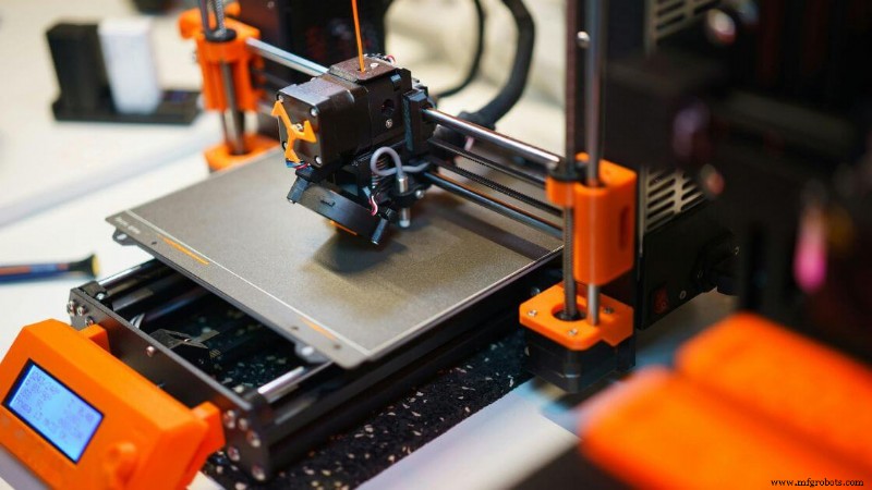
대부분의 사람들은 "3D 프린팅"이라는 말을 들으면 플라스틱 부품을 만드는 소형 데스크탑 기계를 상상합니다. 하지만 뒤에서는 더 많은 일이 벌어지고 있습니다. 우리가 3D 프린팅이라고 부르는 것은 실제로 디지털 디자인을 바탕으로 개체를 레이어별로 제작하는 다양한 기술 그룹입니다.
단단한 블록에서 재료를 깎아내는 전통적인 제조와 달리 3D 프린터는 필요한 것만 추가합니다.
ISO/ASTM 52900-15 표준에 따르면 3D 프린팅은 통 광중합, 재료 분사, 바인더 분사, 분말 베드 융합, 재료 압출, 지향성 에너지 증착, 시트 적층 등 7가지 범주로 구분됩니다. 각각은 서로 다른 접근 방식을 사용하며 작업하는 재료, 예산, 부품의 복잡성에 따라 각각 고유한 장점을 가지고 있습니다.
오늘날 가장 발전된 3D 프린팅 방법 중 일부는 1980년대까지 거슬러 올라갑니다. SLA(광조형술)는 1986년에 특허를 받았으며 그 이후 속도, 세부 묘사, 재료 범위 또는 비용 효율성이라는 서로 다른 목표를 위해 설계된 FDM, SLS 및 MJF와 같은 엄청난 혁신을 보았습니다.
이제 200달러 미만의 데스크톱 시스템과 100만 달러가 넘는 산업용 시스템을 찾을 수 있습니다. PLA 및 ABS부터 금속 분말, 세라믹 및 광중합체 수지에 이르기까지 3D 프린팅 산업은 취미로 하는 사람과 제조 엔지니어 모두를 위한 중요한 도구로 성장했습니다.
이 기사에서는 각 주요 3D 프린팅 유형을 분류하고, 작동 방식을 살펴보고, 이제 막 시작하든 생산 규모를 늘리든 관계없이 귀하의 요구에 가장 적합한 유형을 찾는 데 도움을 드릴 것입니다.
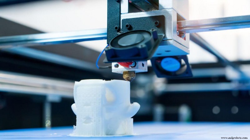
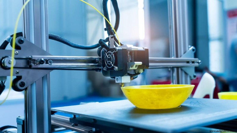
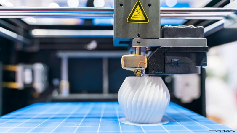 재료 압출은 제작 재료를 노즐을 통해 밀어 넣고 층별로 쌓아 3차원 부품을 형성하는 3D 프린팅 공정 그룹을 의미합니다.
일반적으로 열가소성 물질인 이 재료는 반액체 상태가 될 때까지 가열된 후 컴퓨터 지원 설계 파일에 따라 제어된 경로에 따라 압출됩니다. 각 층은 냉각되면서 이전 층과 융합되어 견고한 구조를 형성합니다.
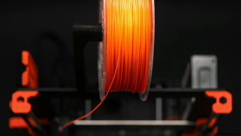
이는 가장 일반적이고 접근하기 쉬운 3D 프린팅 방법 중 하나입니다. 스풀 필라멘트를 사용하는 데스크톱 3D 프린터에서 흔히 볼 수 있지만, 이 카테고리에는 펠릿, 콘크리트 또는 페이스트를 압출하는 대용량 기계도 포함됩니다.
소형 부품을 생산하든 대규모 프로토타입을 생산하든 재료 압출은 설계 및 제작 볼륨에 상당한 유연성을 제공합니다.
지원되는 3D 프린팅 재료의 범위는 광범위합니다. PLA, ABS, PETG와 같은 표준 열가소성 수지가 일반적이지만, 고급 설정에서는 탄소 섬유 복합재, 내열성 폴리머 또는 금속 충전 필라멘트를 처리할 수 있습니다.
일부 기계는 건축이나 식품 모델링에도 사용됩니다.
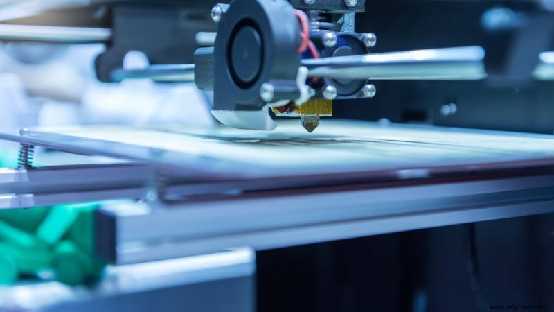
치수 정확도는 장비, 재료 및 환경 제어에 따라 다르지만 일반적으로 ±0.5mm 정도입니다. 돌출부가 있는 개체는 인쇄 중에 붕괴를 방지하기 위해 지지 구조가 필요한 경우가 많습니다. 표면 마감을 개선하고 지지대를 제거하려면 후처리가 필요할 수 있습니다.
재료 압출은 특히 선택적 레이저 소결이나 광조형술과 같은 보다 복잡한 기술과 비교할 때 비용 효율성으로 인해 프로토타입 제작을 위한 주요 선택으로 남아 있습니다. 또한 이 범주에서 널리 사용되는 구현인 융합 증착 모델링의 기초 역할도 합니다.
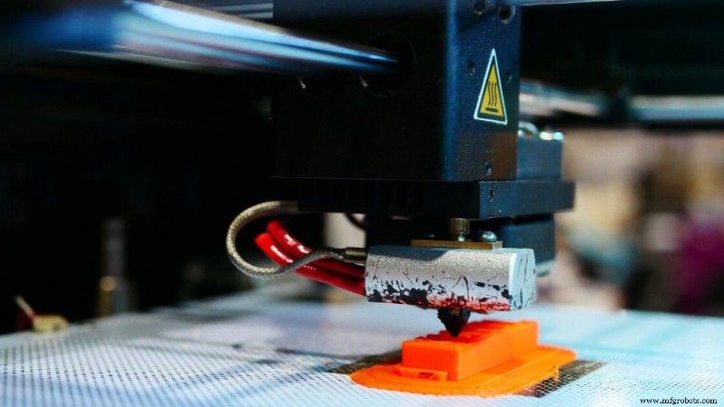
융합 필라멘트 제조라고도 알려진 융합 증착 모델링은 열가소성 필라멘트가 가열된 프린트 헤드에 공급되는 재료 압출 유형입니다. 재료가 녹아 노즐을 통해 압출되어 빌드 플레이트에서 냉각 및 응고되면서 3D 개체의 각 레이어가 형성됩니다.
일반적으로 PLA, ABS, PETG, TPU와 같은 재료를 사용하여 작업하게 됩니다. 보다 고급 옵션에는 폴리카보네이트, ULTEM 및 탄소 섬유나 금속 분말로 채워진 필라멘트가 포함됩니다. 이러한 필라멘트는 부품의 기능 요구 사항에 따라 다양한 기계적 특성을 제공할 수 있습니다.
이 프로세스는 신속한 프로토타이핑, 교육 모델, 소비자 제품 테스트 및 지그나 고정 장치와 같은 제조 보조물과 같은 응용 분야에 이상적입니다.
FDM 3D 프린팅은 대량 생산 전에 부품 형상이나 조립 적합성을 평가해야 하는 제품 개발 워크플로우에서도 흔히 사용됩니다.
일반적인 정확도 범위는 약 ±0.5mm이며 레이어 해상도는 일반적으로 50~300미크론입니다. 인쇄 속도는 재료 및 부품의 복잡성에 따라 다르지만 표준 속도는 40~100mm/s입니다.
장점:
단점:
 3D 바이오프린팅은 바이오 잉크(일반적으로 하이드로겔에 부유하는 살아있는 세포로 만들어짐)를 사용하여 층별로 조직과 같은 구조를 만드는 특수한 형태의 재료 압출입니다.
열가소성 수지나 금속 분말을 사용하는 기존 3D 프린팅 방법과 달리 이 프로세스는 세포 생존 가능성과 생체 재료 호환성을 우선시합니다.
압출은 기능적인 생물학적 기하학적 구조를 형성하는 동시에 살아있는 구성 요소의 손상을 방지할 수 있을 만큼 정확하고 부드러워야 합니다.
이 과정에서 찾을 수 있는 재료에는 알지네이트, 콜라겐, 젤라틴, 피브린과 같은 생분해성 폴리머가 포함됩니다.
이들은 세포의 성장과 배열을 지원하는 비계 역할을 합니다. 구조는 실제 조직을 모방해야 하므로 이러한 재료는 호환성, 유연성 및 혈관 형성 지원 능력을 기준으로 선택되었습니다.
애플리케이션이 빠르게 발전하고 있습니다. 장기 칩 장치, 조직 비계, 재생 의학 모델, 심지어 피부나 연골의 초기 단계 생체 제작 연구에 사용되는 3D 바이오프린팅을 볼 수 있습니다. 이는 단순한 컨셉 모델이 아니라 미래의 이식형 솔루션을 향한 실용적인 단계입니다.
치수 정확도는 프린터 보정 및 바이오잉크 점도에 따라 100~200미크론 또는 그 이상에 이를 수 있습니다. 그러나 성능은 습도, 프린트 헤드 제어, 무균 상태 등의 환경 요인에 따라 달라집니다.
인쇄 속도는 셀 밀도, 노즐 크기 및 하이드로겔 유량에 따라 달라집니다. 일반적으로 인쇄 속도는 속도보다 세포 건강을 유지하는 것이 더 중요하기 때문에 폴리머 압출보다 느립니다.
장점:
단점:
건설용 3D 프린팅은 자동화된 압출 시스템(일반적으로 로봇 팔 또는 갠트리 장착 노즐)을 사용하여 콘크리트와 같은 건설 등급 자재를 적층 형태로 증착하는 대규모 적층 제조 방법입니다.
기존 방법과 달리 3D 프린팅 기술을 사용하여 디지털 모델에서 직접 제작하므로 표준 금형이나 거푸집 없이 벽, 구조 외피, 건물 전체를 레이어별로 제작할 수 있습니다.
일반적으로 이러한 시스템에 사용되는 시멘트질 혼합물, 속경화 콘크리트, 지오폴리머 화합물, 특수 모르타르와 같은 재료를 볼 수 있습니다.
기본 재료의 선택은 엄격한 유동성 및 경화 요구 사항을 충족해야 하며, 구조적 무결성을 유지하면서 각 새 부품 레이어가 이전 부품 레이어와 잘 결합되도록 해야 합니다.
이러한 접근 방식은 지속 가능하고 신속하며 저비용 건설을 목표로 하는 프로젝트에서 전 세계적으로 주목을 받고 있습니다. 저소득층 주택부터 비상 대피소, 예술 건축물까지 적용 범위가 점점 늘어나고 있습니다.
아직 등장하고 있지만 3D 프린터를 사용하여 단 며칠 만에 집 전체나 주요 구조 부품을 제작하여 기존 건축 일정에 비해 몇 주를 단축한 몇 가지 실제 사례를 발견할 수 있습니다.
정확도는 일반적으로 프린터의 빌드 플랫폼 크기, 노즐 정밀도 및 환경 요인에 따라 ±5mm에서 ±10mm 사이입니다. 인쇄 속도는 다양할 수 있지만 직선 또는 반복적인 모양의 경우 수작업보다 빠른 경우가 많습니다. 레이어 해상도는 10mm에서 30mm 사이로 거친 경향이 있지만 마무리 기술을 사용하면 향상될 수 있습니다.
장점:
단점:
Vat 광중합은 빛을 사용하여 액체 수지 층을 선택적으로 경화시켜 고체 부품으로 만드는 3D 프린팅 공정입니다. 특정 파장의 빛에 반응하는 일반적으로 아크릴 기반의 광중합체 수지로 채워진 통으로 시작합니다.
레이저, 디지털 조명 프로젝터 또는 LCD 화면이 이 경화 과정을 매우 정밀하게 안내합니다. 각 포토폴리머 층이 경화됨에 따라 빌드 플랫폼은 다음 층이 형성될 수 있도록 점차적으로 올라가거나 내려갑니다. 이 순서는 전체 개체가 완성될 때까지 반복됩니다.
이 방법을 차별화하는 점은 매우 미세한 디테일과 매우 매끄러운 표면 마감을 생성할 수 있다는 것입니다. 그렇기 때문에 치과용 주형, 복잡한 보석, 소형 의료 부품 등 정밀도가 중요한 응용 분야에 선호됩니다.
치수 정확도는 미세 조정된 기계에서 ±0.1mm 이내이거나 그보다 더 좋을 수 있으며, 빛 노출 및 수지 흐름 동작이 제어되므로 부품 형상이 일관되게 유지됩니다.
또한 이 프로세스는 SLA, DLP, LCD 등 다양한 형식으로 제공되며 각각 약간 다른 광원을 사용하지만 동일한 일반 원리인 광중합에 따라 작동합니다.
이러한 기계에 사용되는 수지는 다양한 제형으로 제공됩니다. 일부는 인성에 최적화되어 있고 다른 일부는 유연성, 투명도 또는 내열성에 최적화되어 있습니다. 일부는 생체 적합성이 있어 의료용 프로토타이핑이나 수술 가이드에 사용할 수 있습니다.
그러나 특정 돌출부나 브리지 기능에는 지지 구조가 필요하며 프린팅 후 수동으로 제거해야 한다는 점을 명심하십시오. 기계적 특성을 개선하고 잔여 끈적임이 없는 깨끗한 표면을 보장하려면 일반적으로 자외선 하에서의 후경화는 필수적입니다.
 SLA(Stereolithography)는 최초로 상업적으로 성공한 3D 프린팅 프로세스였으며 오늘날에도 가장 정확한 프로세스 중 하나로 남아 있습니다. SLA 시스템에서는 UV 레이저가 한 번에 한 층의 감광성 수지를 추적하고 응고시킵니다.
그러면 빌드 플랫폼이 점진적으로 이동하여 각 후속 부품 레이어가 마지막 부품 위에 경화될 수 있습니다. 이는 탁월한 표면 품질을 갖춘 매끄러운 구조를 만들어냅니다.
SLA가 돋보이는 이유는 다양한 특수 수지입니다. 프로토타입용 표준 수지, 내열성을 위한 고온 버전, 탄성 부품을 위한 유연한 옵션, 보석 및 매몰 주조에 사용되는 주조 가능한 공식까지 찾을 수 있습니다. 일부 생체 적합성 수지는 치과 응용 분야 및 의료 기기에 사용됩니다.
일반적인 SLA 프린터는 부품 형상 및 인쇄 설정에 따라 25미크론의 미세한 레이어 해상도와 ±0.1mm에 가까운 치수 공차를 달성합니다. 인쇄 속도가 가장 큰 장점은 아니지만, 결과는 지속적으로 높은 품질과 미세한 디테일을 유지하므로 컨셉 모델이나 정밀 부품의 소규모 생산에 이상적입니다.
장점:
단점:
디지털 라이트 프로세싱(DLP)은 디지털 프로젝터를 사용하여 액체 수지의 전체 층을 한 번에 경화시키는 통 광중합 기술입니다. UV 레이저로 각 단면을 추적하는 광조형(SLA)과 달리 DLP는 광 프로젝터를 사용하여 레이어의 전체 이미지를 플래시합니다.
이 프로세스는 특히 여러 부품이나 더 큰 단면적을 가진 부품을 제작할 때 인쇄 속도를 크게 향상시킵니다.
DLP는 SLA 프린터에 사용되는 것과 유사한 광중합체 수지를 사용합니다. 이러한 재료는 특정 형상에 대한 지지 구조가 필요하며 종종 이소프로필 알코올로 헹구거나 UV 경화와 같은 후처리 단계가 필요합니다. 프로젝터의 각 픽셀은 복셀(기본적으로 3D 픽셀)이 되어 매우 상세한 표면 특징을 구현합니다.
이 방법은 세밀한 디테일과 속도가 필요할 때 특히 유용합니다. 해상도는 SLA와 일치하거나 능가할 수 있지만 프로젝터의 해상도에 따라 크게 달라집니다.
저사양 시스템에서는 픽셀화 아티팩트가 나타날 수 있지만 최신 데스크탑 DLP 프린터는 향상된 광학 기능과 더 작은 픽셀 크기로 이를 크게 완화했습니다.
장점:
단점:
마스크 광조형술이라고도 알려진 LCD 기반 3D 프린팅은 LCD 패널을 사용하여 UV 백라이트의 빛을 선택적으로 차단하고 허용하여 수지를 경화시킵니다. 패널은 스텐실처럼 작동하여 굳혀야 하는 각 레이어의 영역만 노출합니다.
이 레이어별 경화 방법은 DLP와 유사하지만 디지털 프로젝터 대신 LCD 화면을 사용하므로 설정이 더 작고 저렴합니다.
최근 몇 년 동안 LCD 3D 프린터는 저렴한 비용, 높은 해상도, 사용 편의성으로 인해 인기가 급증했습니다. 특히 소비자, 프로슈머, 치과용 또는 보석류 응용 분야용 데스크탑 컴퓨터에서 널리 사용됩니다.
이제 일부 모델에는 4K 및 8K LCD 화면이 탑재되어 디테일을 강화하고 눈에 보이는 픽셀화를 줄여 표면 마감과 해상도를 향상시킵니다.
이 프린터는 DLP 및 SLA 시스템과 마찬가지로 다양한 포토폴리머 수지와 함께 작동합니다. 빌드 볼륨과 화면 품질에 따라 35~100미크론 사이의 레이어 해상도와 약 ±0.1~0.2mm의 치수 정확도를 달성할 수 있습니다.
장점:
단점:
CLIP과 CAL은 통 광중합의 최첨단을 대표하며 적층 가공이 얼마나 빠르고 원활할 수 있는지에 대한 한계를 넓혀줍니다. 이 방법은 개별적인 일시 중지를 통해 수지를 층별로 경화하는 대신 지속적인 인쇄에 중점을 두어 눈에 보이는 층선을 제거하고 기계적 약점을 줄입니다.
Carbon이 개발한 CLIP은 독특한 산소 투과성 창을 사용하여 광원 바로 위에 "데드 존"을 만듭니다. 경화되지 않은 광중합체 수지의 얇은 층은 인쇄 중에 액체 상태로 유지되어 3D 개체가 통에서 지속적으로 위쪽으로 끌어당길 수 있습니다.
결과적으로 매우 매끄러운 표면 마감과 레이어 사이에 잠시 멈출 필요가 없는 부품을 얻을 수 있습니다. 이 프로세스는 또한 부품 강도를 향상시키고 생산 부품에 대한 후처리 필요성을 줄여줍니다.
아직 초기 개발 단계인 CAL은 이 문제에 다르게 접근합니다. 회전하는 액체 수지에 여러 개의 2D 이미지를 투사합니다.
CAL은 모든 각도에서 형상을 동시에 재구성함으로써 체적 경화를 가능하게 합니다. 이를 통해 복잡한 부품을 생산하는 데 필요한 시간이 획기적으로 단축되고 전체 3D 프린팅 부품을 몇 분 만에 생성할 수 있습니다.
장점:
단점:
PBF(분말층 융합)는 레이저나 전자 빔과 같은 고에너지원을 사용하여 미세 분말(일반적으로 폴리머 또는 금속) 층을 선택적으로 융합시키는 적층 가공 공정의 한 범주를 의미합니다.
각각의 새로운 파우더 층이 빌드 플랫폼 전체에 퍼지면서 열원이 특정 영역을 녹이거나 소결하여 층별로 부품의 견고한 단면을 형성합니다.
PBF를 차별화하는 점은 뛰어난 기계적 특성을 지닌 복잡한 형상을 생성하는 능력입니다. 융합되지 않은 파우더가 인쇄된 부분을 둘러싸기 때문에 돌출부와 내부 구조를 자연스럽게 지지합니다.
이로 인해 특히 선택적 레이저 소결과 같은 폴리머 기반 시스템에서 많은 기존 지지 구조가 필요하지 않습니다.
PBF는 광범위한 엔지니어링 등급 재료를 지원합니다. 일반적인 옵션으로는 나일론, 폴리아미드 복합재, 스테인리스강, 티타늄, 알루미늄 등이 있습니다.
이러한 분말은 기계적 강도, 내열성 및 응용 분야별 특성을 고려하여 선택됩니다. 신속한 프로토타입을 개발하든, 기능성 최종 사용 구성요소를 개발하든, 이 프로세스는 인상적인 다양성을 제공합니다.
파우더 베드 융합의 주요 이점 중 하나는 특히 기계적 특성과 내구성 측면에서 3D 프린팅 부품의 사출 성형 품질을 달성할 수 있다는 것입니다.
그러나 이 공정에는 고급 장비, 불활성 가스 챔버(금속 PBF용), 그리고 과도한 분말을 제거하고 표면 마감을 개선하기 위한 숙련된 후처리가 필요합니다.
PBF 시스템은 일반적으로 각 축에서 200~400mm 사이의 빌드 볼륨을 제공합니다. 많은 제조업체는 단일 실행으로 수십 개의 부품을 중첩하는 소규모 배치 생산에 이를 사용합니다. 이러한 확장성은 생산 수준에서 비용 효율적인 적층 제조의 핵심 이점입니다.
SLS는 3D 프린팅 산업에서 사용되는 가장 유명한 폴리머 기반 분말층 융합 방법 중 하나입니다. 이 제품은 고출력 레이저를 사용하여 분말 재료(일반적으로 나일론 또는 폴리아미드 복합재)를 스캔하고 소결하여 견고하고 기능적인 부품으로 만듭니다.
각 단면은 외부 지지 구조 없이 가열된 챔버 내부에서 층별로 융합됩니다.
SLS는 재료 유연성으로 널리 알려져 있습니다. PA12 또는 PA11 나일론을 사용하여 작업하는 경우가 많으며 때로는 탄소 섬유, 유리 구슬 또는 유연한 엘라스토머와 혼합됩니다. 이러한 분말은 강도, 내구성 및 설계 자유도 사이의 견고한 균형을 제공하므로 SLS는 신속한 프로토타입 제작 및 소규모 배치 생산 부품에 이상적입니다.
일반적인 응용 분야에는 하우징, 지그, 브래킷, 고정 장치, 스냅핏 및 기능 테스트 부품이 포함됩니다. 치수 정확도는 일반적으로 부품 길이의 ±0.3mm 또는 ±0.3%로 특정 기존 제조 방법에 비해 경쟁력이 있습니다.
SLS의 레이어 해상도는 일반적으로 100~150미크론 사이입니다. 개별 제작 속도는 프린터와 레이저 출력에 따라 다르지만 여러 부품을 동시에 중첩할 수 있어 처리량이 크게 향상됩니다.
장점:
단점:
Multi Jet Fusion은 3D 프린팅에 사용되는 고급 파우더 베드 융합 방식입니다. SLS와 같은 분말을 소결하기 위해 레이저를 사용하는 대신 MJF는 선택적으로 융합제를 폴리머 분말 베드에 분사한 다음 적외선 열을 적용하여 입자를 결합합니다.
그 결과 더 빠르고 균일한 레이어 융합이 가능해지며 MJF는 적층 가공 분야에서 매우 효율적인 솔루션이 됩니다.
MJF에는 나일론(PA12)이 가장 일반적으로 사용되며 TPU, 폴리프로필렌 및 난연성 소재로 새로운 개발이 확대됩니다. 이러한 엔지니어링 등급 폴리머는 기계적 특성의 강도, 정밀도 및 일관성이 요구되는 기능성 부품에 이상적입니다.
MJF는 단기 생산 부품, 하우징, 브래킷 및 맞춤형 인클로저에 자주 사용됩니다. 내부 기능이 정밀한 구성 요소나 인쇄 후에도 읽을 수 있어야 하는 텍스트에 특히 유용할 수 있습니다.
치수 정확도는 종종 ±0.2~0.3mm 범위에 속하므로 많은 융합 증착 모델링 방법보다 더 정확합니다.
층 두께는 일반적으로 80~120 마이크론입니다. 각 레이어가 전체 단면에 걸쳐 동시에 융합되기 때문에 인쇄 속도는 SLS와 같은 레이저 기반 프로세스보다 훨씬 빠릅니다.
장점:
단점:
선택적 레이저 용융은 고출력 레이저를 사용하여 금속 입자를 조밀하고 강한 부품으로 완전히 녹이는 금속 기반 분말층 융합 공정입니다.
낮은 온도에서 재료를 융합하는 소결과 달리 SLM은 완전히 응고된 레이어를 생성하므로 성능 면에서 전통적으로 제조된 금속 부품에 더 가깝습니다.
SLM은 스테인리스 스틸, 티타늄, 코발트 크롬, 알루미늄과 같은 재료와 함께 작동합니다. 이러한 금속은 항공우주, 자동차, 의료용 임플란트, 산업용 공구 등 강도, 정밀도 및 내구성이 필수적인 산업에서 널리 사용됩니다.
일반적인 치수 정확도 범위는 부품의 형상 및 스캐닝 전략에 따라 ±0.1~±0.2mm입니다. 레이어 해상도는 20~50미크론으로 양호하므로 복잡한 내부 기능을 갖춘 매우 상세한 구성 요소를 프린트할 수 있습니다.
장점:
단점:
직접 금속 레이저 소결(DMLS)은 고출력 레이저가 금속 분말 입자를 층별로 소결하여 복잡한 금속 부품을 만드는 분말층 융합 공정입니다.
선택적 레이저 용해(SLM)와 유사하지만 DMLS는 합금 및 재료 요구 사항에 따라 분말을 완전히 녹이는 대신 금속 녹는점 근처에서 작동할 수 있습니다.
DMLS에 사용되는 스테인레스강, 공구강, 티타늄 합금 및 니켈 기반 초합금을 가장 자주 볼 수 있습니다. 이러한 재료는 항공우주, 산업 공구, 의료 기기 부문에서 일반적으로 선택됩니다.
기능성 프로토타입과 소규모 배치 생산 부품은 특히 기존 제조에 비용이 많이 드는 절삭 작업이 필요한 경우 이 프로세스의 이점을 누릴 수 있습니다.
DMLS는 ±0.1~±0.2mm 범위의 치수 정확도를 달성하고 20~50미크론 사이의 미세한 레이어 높이를 사용합니다. 인쇄 속도는 스캔 전략과 기계 성능에 따라 다르지만 일반적으로 다른 금속 적층 제조 기술과 일치합니다.
장점:
단점:
EBM(전자빔 용해)은 또 다른 금속 분말층 융합 공정이지만 레이저 대신 집중된 전자 빔을 사용하여 입자를 융합합니다.
EBM을 독특하게 만드는 것은 고진공 챔버 내에서 작동하여 산화를 크게 줄이고 고온 재료를 지원한다는 것입니다.
항공우주 및 생물의학 산업에서 널리 채택되는 금속인 티타늄 합금 및 코발트 크롬과 함께 사용되는 EBM을 자주 볼 수 있습니다. 강력한 기계적 특성을 지닌 경량 구조물을 프린팅할 수 있는 능력은 정형외과용 임플란트와 고성능 엔진 부품에 특히 유용합니다.
치수 정확도는 일반적으로 약 ±0.2mm 이상이며, 층 두께는 50~100미크론입니다. 빌드 챔버를 예열하면 잔류 응력을 줄여 뒤틀림을 최소화하면서 부품을 생산할 수 있습니다.
장점:
단점:
 LPBF(레이저 분말층 융합)는 SLM(선택적 레이저 용융) 및 DMLS(직접 금속 레이저 소결)와 같은 레이저 기반 금속 3D 프린팅 기술을 총칭하는 용어입니다.
이 적층 제조 공정은 고출력 레이저를 사용하여 미세한 금속 분말 층을 선택적으로 녹이거나 소결하여 완전히 조밀하고 매우 복잡한 3D 프린팅 부품을 형성합니다. 각 재료 층은 일반적으로 산화를 방지하기 위해 불활성 가스 흐름을 사용하는 통제된 환경에서 증착 및 융합됩니다.
스테인레스 스틸, 티타늄 합금 및 알루미늄을 포함하여 LPBF에서 다양한 3D 프린팅 재료를 사용하는 경우가 많습니다. 이러한 엔지니어링 소재는 중량 대비 강도와 복잡한 형상을 형성할 수 있는 능력으로 인해 항공우주, 의료, 자동차 분야에서 특히 선호됩니다.
치수 정확도는 일반적으로 ±0.1~±0.2mm 사이로, 이는 생산 부품 및 기능성 프로토타입에 충분히 정밀합니다. 층 두께는 일반적으로 20~60미크론 범위로 미세한 표면 디테일이 가능합니다. 인쇄 속도는 레이저 전력량, 스캔 전략 및 부품 복잡성에 따라 다릅니다.
장점:
단점:
재료 분사는 액체 재료의 작은 방울을 빌드 플랫폼에 증착하여 부품을 만드는 정밀 중심 적층 제조 프로세스입니다. 광중합체나 왁스 같은 물질인 경우가 많은 이 물방울은 자외선이나 열 경화를 통해 층층이 고체화됩니다.
이 과정은 2D 잉크젯 인쇄와 유사하지만 평면 이미지를 생성하는 대신 완전히 3차원 개체를 구성합니다.
표면 마감과 디테일이 가장 중요한 경우 재료 분사가 이상적이라는 것을 알게 될 것입니다. 제작 재료는 여러 노즐을 통해 분배되며 때로는 별도의 지지 재료와 함께 분배됩니다. 해당 지지대는 나중에 용해되거나 제거되어 최소한의 수동 정리만으로 깨끗하고 복잡한 형상이 남습니다.
각 물방울이 매우 정확하게 배치되기 때문에 결과 부품은 동일한 프린트 내에서 여러 재료 또는 심지어 여러 색상을 특징으로 할 수 있으며 이는 다른 많은 3D 프린팅 프로세스와 차별화됩니다.
재료 분사는 UV 경화 수지, 탄성 잉크 및 왁스에 자주 사용됩니다. 이러한 재료를 사용하면 시각적 프로토타입 제작, 소프트 터치 구성 요소의 기능 테스트, 심지어 금형 제작까지 가능합니다.
Because it can produce smooth surface finishes and capture ultra-fine resolution, it’s especially useful for design validation, medical visualization models, or overmold simulations in product design workflows.
However, this method does come with trade-offs. Photopolymers used in material jetting generally don’t match the mechanical strength of thermoplastics used in fused deposition modeling. Material costs are also higher, and parts may be sensitive to prolonged UV exposure.
PolyJet is a high-resolution material jetting technology that precisely jets and cures layers of photopolymer using UV light. The process builds parts with exceptional surface finish and detail by depositing droplets layer by layer, similar to an inkjet printer working in 3D. It’s a powerful option if you need visual accuracy, multiple material properties, or color simulation in a single part.
You can choose from a wide range of materials—rigid, rubber-like, transparent, or high-temperature resins—many of which are blendable in real time during printing. This allows you to replicate overmolded parts, simulate silicone or soft-touch textures, and produce full-color prototypes for marketing or ergonomic testing.
PolyJet typically offers dimensional accuracy within ±0.1–0.2 mm and layer heights down to 16 microns.
Print speed depends on the model’s size and complexity, but the ability to jet multiple materials at once increases throughput for multi-property components. It’s most commonly used for concept models, dental or medical devices, and design verification of complex assemblies.
장점:
NanoParticle Jetting (NPJ) is a precision-driven 3D printing process that deposits liquid suspensions containing nanoparticles of metal or ceramic materials. These suspensions are jetted layer by layer, similar to how inkjet printers work—except instead of ink, the droplets contain densely packed particles.
After deposition, the liquid carrier evaporates or is removed, and the remaining solid material is sintered in a post-processing stage to form a high-density part.
This method enables the creation of fine-featured metal or ceramic components. Common 3D printing materials for NPJ include stainless steel, zirconia, and other engineering-grade alloys and ceramics. These parts are ideal for industries that demand miniaturization and high mechanical properties, such as medical, aerospace, and electronics.
You’ll often find NPJ used for prototypes and production parts that require tight tolerances, such as surgical tools or micro-mechanical assemblies. It’s capable of producing intricate geometries and detailed surface textures without the need for traditional support structures, thanks to the inherent self-supporting nature of each layer during the drying stage.
Dimensional accuracy generally falls within ±0.1–0.2 mm, although some shrinkage occurs during sintering. Print speed is moderate and depends on part geometry and the thickness of the printed layers. Layer resolution is usually within 20–50 microns, allowing for highly detailed builds.
Binder jetting is a 3D printing process where a liquid binding agent is selectively deposited onto thin layers of powder, gradually building up a part layer by layer. Unlike energy-intensive methods like laser sintering or melting, this approach relies on adhesion between particles to create what’s called a “green part.”
The materials used in binder jetting are diverse—metals, ceramics, sand, and polymer powders are all common.
Once a part is fully printed, it often requires post-processing to gain final strength. This may involve sintering, infiltration with metals like bronze, or curing, depending on the base material.
Binder jetting stands out for its speed and scalability. Because it doesn’t use lasers or high heat during printing, machines can process layers more rapidly and in larger volumes. However, accuracy and final density often depend on the specific post-processing route used.
Applications range from functional metal components to full-color architectural models made with plaster-like gypsum powder. You’ll also find it used in low- to mid-volume production of parts where traditional manufacturing would be cost-prohibitive.
Because it prints without the need for complex support structures, binder jetting is ideal for geometries that would be challenging with other 3D printing methods.
Metal binder jetting is a subset of the binder jetting process that targets metallic powders. Instead of melting the metal directly, a print head deposits a binding agent onto the metal powder layer by layer.
After printing, the “green” part is sintered in a furnace to fuse the particles and achieve the required strength and density.
Typical materials include stainless steel, tool steel, and cobalt-chrome, which are all known for their mechanical properties and thermal resistance. This makes the process well-suited for end-use parts in aerospace, industrial tooling, and even consumer electronics.
Dimensional accuracy is typically in the ±0.3–0.5 mm range, though sintering shrinkage must be anticipated during the design phase. Print speed is a major advantage since it avoids point-by-point scanning. Layer resolution usually falls between 50 and 100 microns.
장점:
단점:
Sand binder jetting is a form of binder jetting where layers of sand are selectively bonded using a liquid adhesive.
The process creates large-scale molds and cores that are primarily used in metal casting applications. Instead of producing the final part, this method builds complex sand forms that act as temporary structures into which molten metal is poured.
The materials typically include silica sand and specialty foundry-grade sands. These sands are chosen for their thermal stability and compatibility with different casting alloys.
You’ll find this method valuable in industries like automotive, heavy machinery, and aerospace, where intricate or large cast components are needed quickly.
Dimensional accuracy ranges from ±0.5 to ±1 mm, depending on sand grain size and geometry. Although the layer resolution is coarser than polymer-based processes, it’s more than sufficient for foundry-grade precision. One of the standout benefits is the high print speed, especially when producing large molds or multi-part assemblies.
장점:
단점:
 Plastic binder jetting operates by jetting a liquid adhesive onto fine layers of polymer powder. Over successive layers, a “green” object is formed. After printing, parts typically undergo post-processing steps—like curing in an oven or chemical infiltration—to reach final strength and durability.
Common materials used in this process include thermoplastic powders, resin powders, and sometimes full-color composites. These materials can produce vivid, detailed parts that are especially useful for visual prototypes, marketing samples, and moderate-strength components.
Dimensional accuracy usually falls within ±0.3 to ±0.5 mm, depending on geometry and finishing techniques.
Print speed tends to be high because the process avoids laser scanning, making it an efficient option for volume prototyping or display-grade production. Layer resolution typically ranges from 100 to 200 microns.
장점:
단점:
Directed Energy Deposition (DED) is a metal 3D printing process where material is fed directly into a high-energy source—usually a laser, electron beam, or plasma arc—which creates a melt pool on the surface of a substrate.
Wire or powdered feedstock is melted upon contact, then solidifies as you build up the part layer by layer. Unlike powder bed fusion, which forms parts in a static bed, DED uses motion-controlled multi-axis systems to apply material dynamically in various directions.
One of the major strengths of DED is its ability to add material to existing components. You can use it to repair damaged parts, reinforce areas with wear, or add entirely new features to an otherwise finished component.
This makes it incredibly valuable in aerospace, oil and gas, and defense sectors where part costs are high and downtime is expensive.
DED is compatible with a variety of metals, including stainless steel, titanium, nickel-based superalloys, and even composite materials. The process supports rapid deposition rates, which is especially useful for building large parts near net shape. However, you’ll often need follow-up machining or post-processing to achieve precision tolerances or smoother surfaces.
Since shielding gas is critical during energy deposition, a stable inert atmosphere helps prevent oxidation or contamination.
Some systems also enable gradient material transitions by blending powders during deposition.
You should consider DED if you’re looking to extend the life of expensive components, experiment with multi-material designs, or produce large-scale metallic parts that can’t be made efficiently through traditional manufacturing methods.
Laser Directed Energy Deposition (L-DED) is a specific type of DED that uses a focused laser beam to melt metal feedstock, usually in the form of powder or wire directly onto a build surface. This method is excellent for adding new material to existing parts or fabricating large metal structures from scratch.
L-DED supports a wide range of metals including tool steels, titanium, cobalt-chrome, and nickel superalloys.
These materials are typically used in high-performance or mission-critical applications. Think turbine blade repairs, aerospace brackets, or custom medical components where both size and strength matter.
Dimensional accuracy for laser DED generally ranges from ±0.5 mm to ±1 mm. While this is coarser than what powder bed systems can achieve, it’s often sufficient when you plan to machine the part post-build.
The layer resolution typically falls between 300 and 1000 microns, depending on the laser settings, nozzle diameter, and material feed rate.
장점:
단점:
Electron Beam Directed Energy Deposition (EB-DED) is a metal additive manufacturing method that uses a focused electron beam to melt metal wire or powder feedstock, layer by layer.
The process is performed inside a vacuum chamber to prevent oxidation and ensure high purity in the final part. Unlike laser-based systems, the electron beam offers deeper penetration and faster energy transfer, making it well-suited for reactive materials.
EB-DED is commonly used with titanium alloys, nickel-based superalloys, and stainless steels. These materials are ideal for aerospace, energy, and defense sectors—especially when large structural parts or critical repairs are needed.
The vacuum setup not only protects the metal from oxidation but also enhances bonding and thermal stability.
Dimensional accuracy is usually around ±1 mm, depending on the feedstock form, beam stability, and system calibration. Layer resolution is coarse, often ranging from several hundred microns to a few millimeters.
While this limits fine detail, the process shines when you need fast deposition over large areas.
장점:
단점:
Wire Directed Energy Deposition (Wire DED) is a form of metal 3D printing where a spool of metal wire is continuously fed into a melt pool generated by a laser, electron beam, or plasma arc.
This process enables you to build up layers of metal quickly and efficiently, particularly when you’re dealing with large-scale structures or repairs.
Wire DED supports a wide range of materials, including stainless steel, titanium alloys, and aluminum alloys. It’s often chosen for aerospace frames, marine parts, and large industrial structures that benefit from thick wall sections and robust material properties.
Because wire feedstock is easier to handle and generally safer than metal powder, it’s also attractive for operations focused on safety and simplicity.
Dimensional accuracy for wire DED typically ranges around ±1 mm. The print speed can be quite high thanks to the continuous feed, although layer resolution is on the coarser side, often over 1 mm per layer.
Despite this, you can achieve excellent mechanical strength, especially when paired with subtractive finishing processes like CNC machining.
장점:
단점:
Cold spray is a form of directed energy deposition where metal powders are accelerated to supersonic speeds using compressed gas and then directed at a target surface.
Unlike other 3D printing methods that rely on melting, cold spray achieves bonding through solid-state deformation. When the particles hit the surface at high velocity, they plastically deform and adhere without undergoing any melting.
This unique approach enables you to apply material without the thermal stress typically associated with metal additive manufacturing.
This process is well-suited for materials like aluminum, copper, titanium, and other ductile alloys. Because of its low-heat nature, cold spray is often used in the additive manufacturing industry to repair aerospace components, restore damaged surfaces, or apply corrosion-resistant coatings.
It’s also useful for creating functional metal parts with decent mechanical properties, especially when thermal distortion must be avoided.
Dimensional accuracy tends to be relatively coarse, around ±1 mm or more due to the spray nature of deposition. Layer resolution is also limited, so you’ll often need post-processing or machining to achieve precision. However, cold spray offers fast coverage, especially for larger parts.
장점:
단점:
Molten Directed Energy Deposition (DED) refers to additive manufacturing processes where the feedstock—typically metal wire—is fully melted during deposition.
Unlike standard wire DED, molten DED focuses on controlling the melt pool with greater precision or alternative energy inputs, such as variable arc control or plasma transfer. This allows for more consistent material flow and fusion, especially in large-scale metal parts.
Materials commonly used include stainless steels, titanium alloys, and nickel-based superalloys. These are often chosen for applications in shipbuilding, energy infrastructure, and heavy machinery.
Whether you’re fabricating structural frames or adding material to worn parts, molten DED enables you to build big—fast.
Dimensional accuracy is usually coarse, in the range of ±1–2 mm. Layer resolution is also larger, often exceeding 1 mm per pass. But that’s a tradeoff many are willing to make for the speed and size advantages this process delivers.
장점:
단점:
Sheet lamination is a group of 3D printing processes where objects are created by stacking and bonding sheets of material layer by layer.
These sheets, commonly paper, metal foil, or plastic film—are either pre-coated with adhesive or fused during the build process through heat, pressure, or ultrasonic welding.
Once a layer is bonded, a laser or blade cuts the profile of the part, either before or after the bonding stage.
Unlike some additive manufacturing methods that require high-energy sources like lasers or UV light, sheet lamination operates at lower temperatures.
This makes it a more cost-effective option for producing large parts, especially in applications where surface finish or material strength is not the primary concern.
Materials often used in this process include standard office paper for color prototypes, polymer films for lightweight models, or thin metal foils for structural or embedded-function parts. Depending on the bonding and cutting technique used, the level of detail and final mechanical properties can vary.
Sheet lamination is often chosen for its speed, affordability, and ability to create large visual prototypes quickly. Its applications range from architectural models and packaging mockups to experimental builds involving embedded electronics or multi-material stacking.
Laminated Object Manufacturing, or LOM, is a specific type of sheet lamination where layers of adhesive-backed material are bonded together and cut to shape, one layer at a time. It works by feeding sheets—usually paper—over a build platform.
Each layer is bonded using heat and pressure, then shaped with a laser or mechanical blade based on the CAD design.
This process is straightforward and cost-effective, particularly useful when you need a large physical prototype quickly but don’t need engineering-grade mechanical properties. It doesn’t use photopolymers or require a controlled atmosphere, which makes it relatively easy to implement in an office or design studio environment.
Typical materials include standard paper, plastic films, or thin composite sheets. Paper-based builds can even include color by printing graphics onto each sheet before layering. Once the part is finished, excess material is trimmed, and post-processing like sanding or sealing can improve appearance.
The layer resolution of LOM is usually determined by sheet thickness; usually around 0.1–0.2 mm. Depending on blade sharpness and calibration, the dimensional accuracy is within ±0.5–1 mm.
Pros
Cons
Ultrasonic Consolidation is a solid-state additive manufacturing method where thin layers of metal foil are bonded using high-frequency ultrasonic vibrations. Unlike traditional 3D printing methods that rely on high heat or melting, UC fuses metal at a molecular level by vibrating the foil while applying pressure. This allows bonding without reaching the material’s melting point.
The process is part of the broader sheet lamination category in additive manufacturing. Each foil sheet is cut to shape using a CNC-controlled system and ultrasonically welded layer by layer.
Because there’s no full melting involved, this method avoids issues like residual stress or large heat-affected zones—making it ideal when you want to preserve original material properties.
Materials include lightweight metals like aluminum, titanium, and copper alloys—especially in foil form. UC can also embed sensors, wires, or electronics between layers, enabling functional integration in a single part.
Applications are most common in aerospace and defense, where you might need lightweight structures with embedded components, or multi-metal parts for complex mechanical behavior. Its dimensional accuracy typically falls within ±0.2–0.3 mm, though final machining is often performed for tight tolerances.
Print speed is moderate; each weld is fast, but layering takes time due to foil preparation and trimming. Also, the layer resolution depends on foil thickness—usually between 50 to 200 microns.
Pros
Cons
 Additive Friction-Stir Deposition (AFSD) is a solid-state 3D printing process that builds parts without melting the feedstock. Instead of lasers or electron beams, this method uses a rotating tool or nozzle to force metal in solid or near-solid form onto a base surface.
Friction between the tool and material generates enough heat to plastically deform and bond the layers. This energy-efficient process allows you to create or repair metal components while avoiding the residual stresses and porosity often seen in melt-based additive manufacturing methods.
You’ll typically see materials like aluminum, copper, and titanium used in AFSD due to their favorable mechanical properties and thermal conductivity. Since the feedstock stays below its melting point, the final part often retains better structural integrity.
AFSD is ideal for applications requiring large-scale structural builds, localized repair jobs, or multi-metal gradient structures.
It allows the integration of dissimilar alloys without forming brittle intermetallic layers—something difficult with traditional powder bed fusion or fused deposition modeling.
While the dimensional accuracy may still require post-machining for tight tolerances, the process enables unique possibilities for producing high-performance 3D printed parts with minimal distortion.
Beyond the well-known additive manufacturing processes like fused deposition modeling and stereolithography, several specialized or still-developing 3D printing methods are gaining attention.
These techniques often tackle very specific design challenges, whether it’s printing micro-scale features, combining materials in a single build, or achieving full-color surface finishes for display models.
You’ll find these methods pushing boundaries in fields such as biomedical device manufacturing, embedded electronics, and aerospace prototyping.
Hybrid techniques are also emerging, where two or more energy deposition methods (like friction and powder) are combined.
These innovations continue to broaden the scope of 3D printing technology, expanding material compatibility, reducing printing time, and improving part resolution in unique ways.
When your project demands ultra-high precision, such as building medical micro-implants or lab-on-a-chip devices, microscale 3D printing enters the picture. These advanced systems use highly focused energy sources, including lasers or electron beams, to deposit or cure materials at resolutions measured in microns or even nanometers.
At this scale, specialized photopolymer resins and nanoparticle inks become essential. Some methods use two-photon polymerization to cure light-sensitive materials only at the precise focal point of a laser, allowing incredibly detailed structures to be built layer by layer. This results in 3D printed parts with minimal feature size and excellent dimensional accuracy.
Despite its precision, this method is slower than traditional processes and requires careful control over heat, material flow, and shrinkage. However, the benefits are significant when you’re working on microfluidics, drug delivery systems, or advanced electronics packaging.
Drop on Demand (DOD) is a precision-oriented 3D printing method where droplets of build material are selectively deposited only where needed. Unlike continuous inkjet systems, DOD technology triggers each droplet individually, allowing you to achieve tight control over shape and detail. These droplets solidify immediately upon contact or through a curing process like UV exposure.
This process is commonly used for wax patterns in investment casting or small polymer parts that require detailed surface finish and dimensional accuracy. DOD printers often feature two nozzles, one for build material and one for support material that’s later dissolved or removed. Layer height can be as fine as tens of microns, making it ideal for smooth, intricate 3D printed parts.
CFR 3D printing combines traditional polymer extrusion with continuous fiber placement to boost mechanical strength. You feed fibers such as carbon, Kevlar, or glass through a specialized nozzle while depositing a thermoplastic matrix. The result is a high-strength composite that retains lightweight characteristics, something you’d want for functional parts in aerospace, automotive, or tooling applications.
The fiber paths can be customized within your computer-aided design software to align with stress loads, enhancing tensile performance where it’s needed most. Parts produced with this method often outperform metal in strength-to-weight ratio and can replace heavier components in structural designs.
Atomic Diffusion Additive Manufacturing (ADAM) is a metal 3D printing technique that begins with metal rods encased in a polymer matrix. These rods are deposited layer by layer, forming a “green” part that retains the desired geometry but lacks full density. After printing, the part undergoes sintering, where heat causes the metal particles to diffuse and bond, resulting in a fully metallic component.
This process is ideal for complex metal parts that require simpler post-processing and is more cost-effective than some powder bed fusion systems. Since the base material is rod-shaped rather than powder, ADAM minimizes handling hazards and can increase deposition rates. It’s well-suited for prototyping, functional testing, and low-volume production of geometries that are difficult to achieve using traditional manufacturing methods. If you’re looking for a bridge between fused filament fabrication and direct metal laser sintering, ADAM is worth considering for its balance of safety, resolution, and performance
Powder adhesion is a lesser-known additive manufacturing method closely related to binder jetting. Instead of using lasers or high-powered heat sources, it selectively bonds powder using chemical binders or controlled heat. This can involve applying infrared light or heat-absorbing agents to fuse specific regions of thermoplastic or composite powder. Each pass deposits a fine layer of material, which bonds where energy or binder is applied.
While the parts often need post-processing—such as sintering or infiltration—this technique offers flexibility in handling materials that respond poorly to direct melting. Maintaining a consistent powder bed is critical to ensure layer accuracy and part geometry. Powder adhesion processes are especially appealing for industries focused on prototyping and product development where powder bed fusion might be too costly or intense. As with most powder-based 3D printing methods, it emphasizes surface finish, build plate stability, and post-processing to refine mechanical properties and dimensional tolerances.
ColorJet Printing (CJP) is one of the few 3D printing processes capable of producing full-color models directly from CAD files, making it ideal when you need high-fidelity visuals for presentations, educational models, or marketing prototypes.
Each layer is formed by selectively depositing liquid binder and colored ink droplets onto a thin layer of gypsum powder. Over time, the printed part is built layer by layer with accurate coloring embedded in the structure.
After printing, parts can be strengthened and sealed using infiltration materials like epoxy resin, enhancing durability and vibrancy. The resulting 3D printed parts don’t possess high mechanical strength but excel in aesthetics and detail—particularly useful for architecture, figurines, and medical demonstrations.
ColorJet technology reflects the diverse applications of inkjet printing in additive manufacturing. Unlike other types of 3D printing that prioritize strength, CJP focuses on appearance, offering vibrant models at a lower cost and faster turnaround than polymer-based SLA or FDM 3D printing methods.
Selective Heat Sintering (SHS) is a thermoplastic-based additive manufacturing method that uses a thermal printhead to fuse powder rather than relying on high-power lasers like those used in selective laser sintering (SLS). The process is energy-efficient, operating at lower temperatures, and is well-suited for quick prototyping with polymers like nylon or polylactic acid (PLA).
In each layer, the printhead selectively applies heat to regions of the powder bed based on your 3D model.
As new layers are deposited, they fuse together and gradually build up the object. Since the heat input is lower than in laser sintering, SHS may result in parts with reduced mechanical properties and rougher surface finish, making it better suited for concept models than production parts.
If you’re exploring different types of 3D printing for prototyping without the cost and safety demands of laser-based machines, SHS offers an approachable entry point. It also supports workflows with smaller desktop machines and doesn’t require specialized build chambers.
Laser Metal Deposition (LMD) is a form of directed energy deposition that exclusively uses a laser as the energy source to melt metal feedstock—either wire or powder—as it is deposited. Unlike electron beam melting (EBM) or plasma-based systems, LMD is often integrated with CNC machines to convert them into hybrid platforms that combine additive and subtractive manufacturing in one setup.
This method is ideal for adding features to existing components or producing near-net-shape parts with minimal material waste. It enables precise control of the melt pool, which can help reduce thermal stress and improve overall surface finish compared to more generalized DED systems.
While it shares many traits with other 3D printing processes, its laser-based control and ability to repair or modify components mid-life make it particularly appealing for aerospace and industrial tooling applications.
Multi-Jet Modeling (MJM) is a material jetting technique where multiple print heads dispense photopolymers or waxes in parallel lines across the build area. Each droplet is cured by UV light or solidified by cooling, depending on the material used.
This method stands out from typical inkjet printing by offering simultaneous deposition of support and build materials, allowing you to fabricate complex geometries with minimal post-processing.
Thanks to its fine resolution, sometimes under 20 microns, MJM is well-suited for concept models, investment casting patterns, and even dental devices. Because you can vary materials between jets, MJM can also create gradient structures or embed variable mechanical properties in a single build. While not the fastest of the 3D printing methods, its precision and surface quality give it a place in high-end product design and prototyping workflows.
Powder Bed and Inkjet Head (PBIH) printing works by laying down thin layers of powder, often metal or ceramic, and then selectively depositing a liquid binder through an inkjet print head.
This technique is essentially a type of binder jetting, where the deposited binder holds the part together in a “green” state before final sintering or infiltration.
What makes PBIH unique is its material flexibility. It’s often used for research applications, small-batch production, or parts that require advanced ceramics or metal alloys. Because no lasers or thermal energy are used in the printing stage, there’s less warping and distortion, making it ideal for geometrically complex parts.
While mechanical properties depend on post-processing, this method is becoming a valuable tool in your 3D printing toolkit if you’re working with unconventional or fragile materials.
Photopolymer Jetting (PJ) is very similar to PolyJet 3D printing but can differ depending on the printer brand or specific system design. In this process, UV-curable photopolymers are jetted as tiny droplets onto the build plate and solidified with ultraviolet light.
The layer height can be extremely fine, often producing parts with a smooth surface finish and high dimensional accuracy.
Some PJ systems offer multiple nozzles for different material types, allowing you to create multi-color or multi-material prints within a single build. Other versions provide temperature-controlled print heads to maintain material viscosity for consistent droplet formation.
Because of its precision and quality, PJ is widely used in fields such as product design, dental modeling, and visual prototyping—where aesthetics and surface detail are more important than load-bearing performance.
 When choosing a 3D printing technology, start by identifying the base material that fits your project—thermoplastics, metal powders, ceramics, or photopolymers.
If you’re producing functional parts with high mechanical properties, selective laser sintering (SLS) or direct metal laser sintering (DMLS) may be better than basic fused deposition modeling (FDM).
For visual models or concept parts, stereolithography (SLA) or inkjet printing methods like Multi Jet Fusion (MJF) or PolyJet could deliver excellent surface finish and detail.
Geometry matters too. Are there overhangs, internal channels, or thin walls?
Processes like powder bed fusion or vat photopolymerization handle complex geometries better than material extrusion.
Budget also plays a role—binder jetting can offer lower unit costs at medium volumes, while traditional FDM 3D printers remain cost-effective for prototyping and consumer use.
Consider your accuracy and tolerance requirements. Some technologies like SLA or DMLS consistently hit sub-0.1 mm tolerances.
Others, such as large-format material extrusion or DED, may produce larger deviations but accommodate bigger build volumes.
Lastly, don’t overlook post-processing. Support removal, sanding, infiltration, and heat treatments all affect lead time and cost. If speed and minimal finishing matter most, aim for processes with clean support strategies or automated post-processing workflows.
If your top priority is accuracy, vat photopolymerization—especially SLA and DLP—is your best bet. These methods can achieve resolutions as fine as 25–50 microns, producing sharp edges, smooth surface finishes, and intricate features.
For high-precision metal parts, powder bed fusion technologies like DMLS or SLM are also excellent, often maintaining tolerances of ±0.1–0.2 mm.
However, final accuracy still depends on post-processing like machining or heat treatment to correct for shrinkage.
Material jetting methods such as PolyJet and photopolymer jetting also excel in accuracy and are ideal for smaller components that need tight dimensional control and visual detail.
In contrast, FDM 3D printing generally offers lower resolution and visible layer lines, though tuned machines can achieve decent results—especially for low-cost prototyping or fixtures where tolerances are less critical.
So, if you’re aiming for ultra-precise parts, start with SLA, DLP, or PolyJet, and consider metal powder bed fusion when strength and dimensional fidelity must combine.
Fused deposition modeling (FDM) is the most widely used 3D printing method across consumer, educational, and industrial segments.
This material extrusion process dominates due to its affordability, ease of use, and wide availability of plastic filaments.
Desktop FDM 3D printers are often priced under $500, making them ideal for classrooms, hobbyists, and small businesses. Many product designers and startups use them for prototyping and early-stage development.
Industrial FDM systems can handle engineering-grade thermoplastics with higher melting points, enabling production runs of durable parts. The popularity of FDM stems from its low entry barrier and the scalability it offers across multiple use cases.
Powder bed fusion (PBF), including selective laser sintering and selective laser melting, is the best method for printing intricate geometries.
It excels at producing parts with internal channels, fine lattice structures, and unsupported overhangs, especially when using polymer powder or metal powder as the base material.
Resin-based vat photopolymerization processes, like SLA or digital light processing, also perform exceptionally well with fine features and delicate structures. They provide high-resolution prints and are favored in industries requiring precision, such as dental modeling and medical devices.
Binder jetting offers similar freedom since the surrounding powder bed supports overhangs naturally. However, keep in mind that final properties depend on post-processing like sintering or infiltration. If you’re designing components with high complexity, these technologies offer the greatest design freedom.
SLA consistently delivers the smoothest surface finish among all 3D printing methods. It uses a UV laser to cure liquid resin layer by layer, producing minimal layer lines and high detail. This makes SLA ideal for visual prototypes, jewelry design, or dental models.
Material jetting also ranks high in surface quality. These systems jet tiny droplets of photopolymer and cure them instantly with UV light. The result is a nearly polished surface without the need for sanding or polishing.
For other methods like FDM or SLS, achieving similar finishes usually requires additional post-processing. Sanding, vapor smoothing, or coating can reduce visible layer lines, but the base print typically won’t match the native smoothness of photopolymer technologies.
Fused deposition modeling (FDM) is typically the most affordable 3D printing method available. You’ll find low-cost desktop machines under $500, and basic thermoplastic filaments are inexpensive and widely accessible.
This makes FDM ideal for hobbyists, educators, and startups experimenting with prototyping or concept models.
Even in small production environments, its low material cost and minimal support requirements keep unit costs down.
For large prints or complex parts, however, FDM may not always remain the cheapest. Resin printers and binder jetting with gypsum can also offer cost-efficiency, especially when accuracy or color modeling is essential and post-processing is minimal.
Powder bed fusion (PBF) for metals, especially DMLS, SLM, and EBM is currently the most expensive form of 3D printing. These machines rely on high-powered lasers or electron beams, requiring precise energy deposition, inert gas handling, and extremely fine metal powder.
The cost goes beyond just the equipment. You’ll also have to factor in powder handling systems, post-processing tools, and highly trained technicians. Parts may need heat treatment or machining for final tolerances, adding labor and time.
These systems are often used in aerospace or medical sectors where performance justifies the investment, but for most users, the price tag is a major barrier to entry.
Continuous liquid interface production (CLIP), developed by Carbon, is among the fastest 3D printing processes. It builds parts continuously without stopping between layers, unlike most layer-by-layer techniques.
In other high-speed categories, multi jet fusion (MJF) and binder jetting also perform well. These methods apply entire layers of powder and binder in one pass, cutting down build time significantly for certain geometries.
Material extrusion can be fast when using pellet-fed systems and large nozzles, though you trade off fine detail. If you need production speed without sacrificing resolution, MJF and DLP (digital light processing) offer a strong balance.
Powder bed fusion processes, specifically DMLS, SLM, and EBM are the best options for metal 3D printing. They produce fully dense, high-strength metal components that can match or exceed the performance of cast or machined parts.
These technologies are especially effective for complex geometries, tight tolerances, and critical applications in aerospace, medical, or tooling.
Proper post-processing like support removal, surface finishing, and thermal treatments ensures optimal results.
Binder jetting is an alternative for larger batches or lower-cost metal parts. While mechanical properties may be slightly lower, it offers faster throughput and lower material costs. For repairs or large features, directed energy deposition (DED) provides added flexibility.
Yes, we’ve covered a lot, but here’s the truth:choosing the right 3D printing method isn’t about picking the “best” one. It’s about finding the one that fits you.
Each process, from simple fused filament fabrication (FDM) to high-end metal printing like DMLS or EBM, has its own strengths, costs, and materials. And whether you’re building a quick prototype, a functional part, or something that looks like it came out of a sci-fi movie, there’s a 3D printing solution waiting for you.
Maybe you’re just starting out with a low-cost desktop printer and some PLA. Or maybe you’re working with engineering-grade materials for aerospace parts.
Either way, this technology lets you create faster, smarter, and more flexibly than traditional manufacturing ever could. Today, 3D printing isn’t just for experimenting, it’s shaping real production across industries.
가장 좋은 부분은? You don’t have to do it all alone. If you’re unsure which path to take, reach out to experts and 3D printing service provider like 3ERP who know the machines, the materials, and the methods.
Your perfect match isn’t just out there, it’s already printing.
CNC 기계
오디오 믹서/믹싱 콘솔은 오디오 신호를 결합한 다음 수정하는 장치입니다. 그런 다음 수정된 오디오 신호를 합산하여 출력 신호를 생성합니다. 종종 디지털 또는 아날로그 형식의 오디오 믹서를 찾을 수 있습니다. 아날로그 믹서는 연산 증폭기 집적 회로를 통합하는 반면 디지털 유형은 디지털 신호 처리 기술을 사용합니다. 오늘의 포스트에서는 간단한 오디오 회로를 만드는 5가지 방법에 대해 논의할 것입니다. 우리가 사용할 구성 요소에는 입력 연산 증폭기, 커패시터 및 저항이 포함됩니다. 1. 오디오 믹서 회로는 어떻게 작동합니까? 일
그 역사 동안 금속 주조는 검에서 풍력 터빈에 이르기까지 모든 것을 만드는 데 사용되었으며 오늘날에는 고품질 금속 부품을 만드는 가장 가치 있고 다재다능한 방법 중 하나입니다. 메탈 캐스팅이란 무엇입니까? 금속 주조 용융된 액체 금속을 금형에 붓는 것과 관련된 제조/정밀한 공정입니다. 금형의 내부 구조는 만들어지는 부품의 부정적인 인상과 결합되어 용융 금속이 금형 내에서 냉각되고 응고될 때 최종 부품의 형상을 형성합니다. 완성된 부품은 금형에서 제거됩니다. 금속 주조에는 다양한 종류가 있으며, 각각 사용 분야에 따라 고유한