

제조공정

산업 제조
탄소강 및 합금강 단조
탄소(C) 및 합금강의 단조는 금속 가공 공정을 구성하며, 이는 원하는 구성 요소 형상으로 재료를 형성하는 동시에 단조 재료의 주조 구조를 미세화하고 수축 공극을 치유하고 기계적 특성을 개선하는 능력을 가지고 있습니다. 재료. 완성된 부품의 형상과 사용되는 단조 공정에 따라 다르지만 후속 가공량도 줄어듭니다.
주조 잉곳은 잉곳에서 직접 단조하거나 잉곳에서 열간 가공된 블룸 또는 빌렛에서 단조의 전통적인 출발점이었습니다. 연속주강이 널리 사용됨에 따라 현재는 일반적으로 연속주조 제품이 초기 스톡으로 사용됩니다. 주조 잉곳, 압연 및 주조 블룸 및 빌렛 외에 단조의 기타 출발 재료는 판, 막대 및 막대, 강철 주물입니다.
철과 강철의 단조는 철기 시대의 시작과 함께 시작되었습니다. 그 당시 해머링에 의한 열간 가공은 단철을 생산하고 단철과 강철로 제품을 만드는 과정의 일부였습니다. 고급 철광석, 목탄 및 플럭스를 사용하는 조 제련로는 유용한 원료를 생산하기 위해 손으로 함께 단조 용접해야 하는 소량의 철을 생산했습니다. 처음에는 이것이 당시 단조의 주요 목적이었습니다. 일반적으로 산업혁명의 시작은 철강 단조에서 시작되었다고 알려져 있다. 이 긴 역사에도 불구하고(또는 그 때문에) 강철 단조는 직관적이고 경험적인 과정입니다.
단조품은 일반적으로 개방형 단조품과 폐쇄형 단조품의 일반적인 분류로 시작하여 여러 가지로 분류됩니다. 또한 마감에 가까운 요소 또는 완성된 부품의 치수 및 세부 요구 사항을 충족하기 위해 기계로 단조에서 제거해야 하는 스톡(커버)의 양에 따라 분류됩니다. 마지막으로 단조품은 해머 업셋 단조품, 링 압연 단조품 및 다중 램 프레스 단조품과 같이 제조에 필요한 단조 장비 측면에서 더 분류됩니다. 다양한 분류 중에서 마감에 가까운 요소를 기반으로 한 분류는 강도 및 응력 부식 저항성과 같은 단조 고유의 특성과 가장 밀접한 관련이 있습니다. 일반적으로 완성품의 요구사항을 만족시키기 위해 최소한의 가공을 필요로 하는 단조품의 특성이 가장 좋습니다.
ASTM 사양 A 788에 따라 강철 단조는 재료를 통합하고 원하는 모양을 생성하는 실질적으로 압축적인 소성 작업의 산물입니다. 소성 가공은 해머, 프레스 단조 기계 또는 링 롤링 기계로 수행할 수 있으며 본질적으로 단조된 구조를 생성하기 위해 재료를 변형해야 합니다. 열간 압연 작업은 단조용 블룸 또는 빌렛을 생산하는 데 사용할 수 있습니다. 단조품은 단조 온도에 따라 다음 세 가지 등급으로 나눌 수 있습니다.
강철의 단조 제품 형태에는 판, 형상, 막대, 시트, 스트립, 튜브, 파이프, 압출 및 단조가 포함됩니다. 일반적으로 단조품에는 압출물이 포함되지만, 단조품의 정의에는 압연판 및 봉재가 포함되지 않습니다. 이는 단조품이 요구되는 부품의 완성된 형상과 거의 일치하는 것 외에 때때로 열간 압연 판과 관련된 두께 약화 또는 때때로 열간 압연 봉과 관련된 중심 불건전함을 통해 층상 개재물의 특성을 나타낼 것으로 예상되지 않기 때문입니다.
탄소강 및 합금강은 일반적으로 가장 단조된 재료이며 열간 단조, 온간 단조 또는 냉간 단조 공정과 표준 장비를 사용하여 다양한 모양으로 쉽게 단조됩니다. 탄소강 및 합금강의 단조 온도 선택은 탄소 함량, 합금 조성, 최적의 가소성을 위한 온도 범위 및 공작물 단조에 필요한 감소량을 기반으로 합니다. 이 중 탄소 함량이 단조 상한 온도에 가장 큰 영향을 미칩니다.
많은 수의 사용 가능한 구성에도 불구하고 이 범주의 모든 재료는 본질적으로 유사한 단조 특성을 보여줍니다. 이에 대한 예외는 황화물과 같은 자유가공 첨가제가 포함된 강인데, 이러한 재료는 비자유 가공 등급보다 단조하기가 더 어렵기 때문입니다. 일반적으로 탄소강 및 합금강의 열간 단조성은 변형률이 증가함에 따라 향상됩니다. 작업성 향상은 주로 높은 변형률에서 발생하는 변형열의 증가에 기인합니다.
유용한 모양을 생산하는 다른, 때로는 더 경제적인 방법보다 단조를 선택하는 정당성은 몇 가지 고려 사항을 기반으로 합니다. 단조재료의 기계적 성질은 작업 중 주요 금속류 방향으로 최대화됩니다. 복잡한 모양의 경우 단조만이 주요 적용 하중과 평행하게 금속 흐름을 유도하고 단조 재료의 원래 구조를 한도 내에서 제어할 수 있는 기회를 제공합니다. 미세 구조의 미세화는 온도, 방향 및 단조 재료에서 단조 형상으로 감소하는 정도의 함수입니다. 재료의 구조적 무결성을 최대화하면 설계 구성을 개선할 수 있으며 결과적으로 무게를 줄일 수 있습니다. 복잡한 단조 구성에서 특성을 최적화하기 위해 금속 흐름을 적절하게 제어하려면 일반적으로 금형 단조 전에 한 번 이상의 업셋 작업이 필요하며 금형 분할 라인에서 플래시 형성을 방지하기 위해 중공 단조 또는 역압출이 필요할 수 있습니다.
강철 단조품이 수행하고자 하는 기능 때문에 단조 설계에는 종종 열처리된 단면 크기가 크고 불규칙한 모양이 될 수 있으므로 세 가지 주요 축, 즉 (i) 세로 방향 모두에서 상당한 응력이 가해질 수 있습니다. , (ii) 가로 및 (iii) 짧은 가로. 출발 재료 크기와 단조 단계를 신중하게 선택하면 단조가 세 방향 모두에서 유리한 특성을 나타낼 수 있습니다. 다른 예에서, 예를 들어 업셋 디스크 단조에서 전체 원주를 중심으로 반경 방향으로 유리한 기계적 특성을 얻을 수 있으며 이는 압연 플레이트에서 단순히 절단된 디스크에서 가능합니다.
열간 단조 동작
탄소강 및 합금강을 복잡한 형태로 열간 단조하는 것은 자유가공 등급을 제외하고는 위조성 측면에 의해 거의 제한되지 않습니다. 단면 두께, 형상 복잡성 및 단조 크기는 대부분 가열된 공작물이 냉각 금형과 접촉할 때 발생하는 냉각에 의해 제한됩니다. 이러한 이유로 해머와 같이 다이 접촉 시간이 비교적 짧은 장비는 강철의 복잡한 형태를 단조하는 데 선호되는 경우가 많습니다.
위조 가능성 – 단조성은 압축 하중 하에서 균열 없이 흐를 수 있는 강철의 상대적 능력입니다. 재황화 및 재인산화 등급을 제외하고 대부분의 탄소강 및 저합금강은 일반적으로 우수한 단조성을 갖는 것으로 간주됩니다. 다양한 등급의 강 간의 단조 거동의 차이는 단조 거동에 의한 강 선택에 거의 영향을 미치지 않을 정도로 작습니다. 그러나 단조를 위한 재황 또는 재인강의 선택은 일반적으로 단조에 의한 생산을 고려하는 주요 이유 중 하나가 후속 가공 작업을 피하기 때문에 단조가 광범위하게 기계가공되어야 하는 경우에만 정당화되며 이러한 상황은 드뭅니다.
강의 단조성을 측정하는 일반적인 방법 중 하나는 열간 비틀림 테스트입니다. 이름에서 알 수 있듯이 이 테스트는 가열된 막대 샘플을 비틀어서 테스트 재료의 가능한 고온 작업 온도 범위를 포함하도록 선택된 다양한 온도에서 파괴되는 것을 포함합니다. 파단까지의 비틀림 횟수와 일정한 속도로 비틀림을 유지하는 데 필요한 토크가 보고됩니다. 비틀림 횟수가 가장 큰 온도가 이러한 최대값이 있는 경우 시험 재료의 최적 열간 가공 온도로 가정합니다. 열연 시험에 의해 결정된 여러 탄소강의 단조성은 그림 1에 나와 있습니다. 다음과 같은 다양한 기타 시험은 강재의 단조성을 평가하는 데 사용됩니다.
변형률이 위조성에 미치는 영향 – 강의 단조성은 일반적으로 변형률이 증가함에 따라 증가합니다. 이 효과는 열간 비틀림 시험(그림 1)에서 저탄소강에 대해 나타났으며, 여기서 비틀림 속도가 증가함에 따라 파손까지의 비틀림 횟수가 증가합니다. 더 높은 변형률에서 위조성이 개선된 것은 더 높은 변형률에서 생성된 변형 열의 증가로 인한 것으로 믿어집니다. 그러나 변형열로 인한 과도한 온도 상승은 초기 용융으로 이어져 위조성 및 기계적 특성을 저하시킬 수 있습니다.
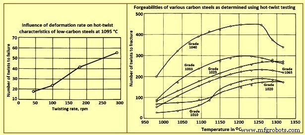
그림 1 다양한 탄소강의 변형률과 위조성의 영향
유동 응력 및 단조 압력 – 유동 응력 및 단조 압력은 열간 비틀림 시험에서 생성된 토크 곡선 또는 열간 압축 또는 인장 시험에서 얻을 수 있습니다. 이 곡선의 데이터는 이 합금 그룹에 대한 상대 단조 압력 요구사항이 일반적인 열간 단조 온도에서 크게 변하지 않는다는 것을 보여줍니다. 고도로 합금된 재료에는 상당히 더 큰 압력이 필요하며 이 합금 재료도 감소가 증가함에 따라 단조 압력이 더 크게 증가합니다.
변형률이 단조 압력에 미치는 영향 – 주어진 강철에 필요한 단조 압력은 변형률이 증가함에 따라 증가합니다. 저탄소강에 대한 연구에 따르면 변형률의 영향은 더 높은 단조 온도에서 더 두드러집니다. 이 효과는 다양한 온도와 변형률에서 단조된 저탄소강에 대한 응력-변형률 곡선을 제공하는 그림 2에 나와 있습니다. 합금강에서도 유사한 효과가 관찰되었습니다.
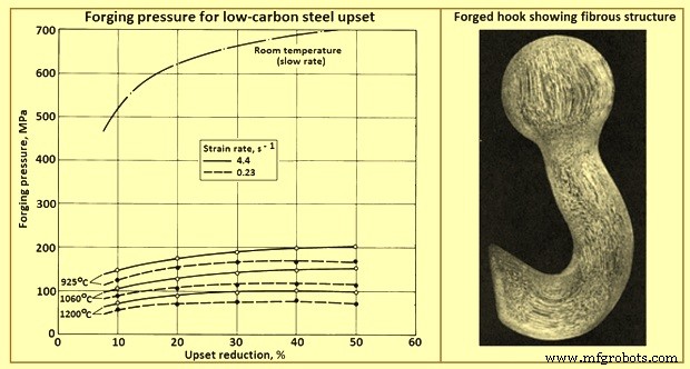
그림 2 다양한 온도와 두 가지 변형률에서 저탄소강 업셋을 위한 단조 압력
단조용 강재 선택
단조용 탄소강 및 합금강 잉곳, 블룸, 빌렛 및 슬래브는 대략적인 단면 치수로 열간 압연 또는 주조되므로 직진도, 캠버, 비틀림 및 평탄도 공차가 적용되지 않습니다. 단조용 철강 반제품은 지정된 중량 또는 지정된 길이로 생산됩니다.
표면 조절 – 단조용 철강 반제품은 표면 결함을 제거하거나 최소화하기 위해 스카핑, 치핑 또는 연삭으로 컨디셔닝할 수 있습니다. 그러나 표면 컨디셔닝에 관계없이 제품에 여전히 표면 결함이 있을 수 있다는 점을 염두에 두어야 합니다.
무게 허용 오차 – 빌렛, 블룸 및 슬래브의 허용 오차는 개별 조각 또는 무게가 18톤 미만인 로트의 경우 종종 +/- 5%입니다. 그 이상의 중량을 가진 로트는 종종 +/- 2.5%의 중량 허용 오차가 적용됩니다.
절단 – 단조용 강재 반제품은 일반적으로 열간 전단에 의해 일정한 길이로 절단됩니다. 강철 성분에 따라 열간 톱질 또는 화염 절단을 사용할 수도 있습니다.
품질 – 단조용 철강 반제품에 적용되는 품질은 내부 건전성 정도, 화학 조성의 상대적 균일성, 표면 결함의 상대적 자유도 등 다양한 요인에 따라 달라집니다.
단조 품질의 반제품 강은 후속 열처리 또는 기계 가공 작업을 포함할 수 있는 열간 단조 응용 분야에 사용됩니다. 이러한 응용 분야에서는 화학 성분과 철강 생산을 비교적 세밀하게 제어해야 합니다.
단조 부품을 위한 강철의 선택은 설계 과정의 필수적인 부분이며 허용 가능한 성능은 이 선택에 달려 있습니다. 완성된 부품의 최종 용도를 주의 깊게 이해하면 필요한 기계적 특성, 표면 마감 요구 사항, 비금속 개재물에 대한 허용 오차, 수반되는 검사 방법 및 기준을 정의하는 데 도움이 됩니다.
단조 품질의 강철은 광범위한 화학 조성으로 생산됩니다. 각각의 용융 및 압연 방식으로 테스트 및 품질 평가 수준이 수행됩니다. 필요한 경우 비금속 개재물의 발생 수준과 같은 강철에 대해 하나 이상의 특수 품질 제한을 지정할 수 있습니다. 경우에 따라 더 높은 신뢰성을 위해 강철을 진공 아크 재용해 또는 일렉트로슬래그 재용해 공정을 거쳐야 합니다.
미세 합금강의 사용은 최근 몇 년 동안 자동차 크랭크 샤프트와 같은 응용 분야에서 발전했습니다. 이러한 강철은 일반적으로 바나듐 또는 니오븀이 소량(0.05% ~ 0.1%) 첨가되며 열처리되지 않은(단조된 상태) 조건에서 허용 가능한 특성을 얻을 수 있습니다. 결과적으로 이러한 합금은 열처리 사이클이 없기 때문에 주조 공정과 경제적으로 경쟁력이 있는 동시에 단조 공정의 장점을 유지합니다.
디자인 요구사항 – 단조 부품을 위한 강철의 선택은 일반적으로 강도 대 인성, 응력 부식 저항 대 중량, 제조 비용 대 유용한 하중 전달 능력, 생산 비용 대 유지 보수 비용, 철강 원료 대 단조의 총 제조 비용. 재료 선택에는 또한 용융 방식, 성형 방법, 기계 가공 작업, 열처리 절차, 사용 시간에 따른 특성 열화, 단조될 강의 기존 기계적 및 화학적 특성을 고려하는 것이 포함됩니다.
효율적인 단조 설계는 가해지는 하중과 일치하는 최소 재료량, 생산성 및 원하는 기대 수명으로 최대 성능을 달성합니다. 강철을 설계 구성 요소와 일치시키기 위해 강철은 먼저 강도와 인성을 평가한 다음 온도 및 환경에 대한 안정성을 인증합니다. 그런 다음 최적의 철강은 생산성과 경제성을 위해 분석됩니다.
고장 분석은 요구 사항에 강철 속성을 일치시키는 데 유용한 데이터 소스입니다. 설계 응력 범위 내에서 작동하는 동안 구성 요소의 고장이 발생할 수 있습니다. 조기 파손의 원인 중 하나는 단조의 바람직한 입자 흐름과 함께 임계 설계 응력의 적절한 방향이 부족하기 때문입니다. 또한 시간과 서비스에 따른 속성 저하로 인해 예상치 못한 고장이 발생할 수 있습니다. 예를 들어 지속적인 인장 응력으로 인해 발생하는 응력 부식 균열은 일반적인 주변 환경에서도 발생할 수 있습니다. 이러한 조건에서 파손은 노출된 최종 입자와 일치하는 단조의 위치에서 가장 많이 발생합니다. 파손 분석은 과도한 결정립 성장, 비금속 불순물의 포함, 부적절한 단조 관행으로 인한 입자 흐름 접힘, 단조 야금 구조의 부족, 과도한 가공으로 인한 응력 상승제의 부주의한 생산과 같은 조기 파손의 다른 원인을 밝혀낼 수 있습니다. 날카로운 필렛 또는 조립 불량으로 인한 것입니다.
단조가 속성에 미치는 영향
탄소강 또는 합금강 막대 또는 빌렛에서 복잡한 형상을 성형하려면 먼저 강철을 적절한 시작 형상(예비 성형)으로 '배열'한 다음 최종 부품 형상으로 흐르게 해야 합니다. 이러한 금속 재배열은 강의 경도 및 강도에 거의 영향을 미치지 않지만 특정 기계적 특성(연성, 충격 강도 및 피로 강도와 같은)은 향상됩니다. 이러한 특성의 개선(그림 2)은 단조가 (i) 분리를 없애고, 다공성을 치유하고, 균질화를 돕고, (ii) 입자 흐름과 평행한 기계적 특성을 향상시키는 섬유 입자 구조를 생성하고, (iii) 다음과 같이 감소하기 때문에 발생합니다. -캐스트 입자 크기.
단조 감소의 함수로서 열처리 강의 연성 및 충격 강도의 일반적인 개선은 그림 3에 나와 있습니다. 이 데이터는 각 경우에서 최대 연신율 방향에서 최대 개선이 발생함을 보여줍니다. 인성과 연성은 일정한 양의 감소 후에 최대값에 도달하고 그 이후에는 더 감소하는 것이 거의 가치가 없습니다.
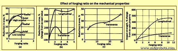
그림 3 단조비가 기계적 특성에 미치는 영향
표 1은 어닐링, 정규화, 담금질 및 템퍼링 조건에서 저탄소 및 중탄소강 단조품의 전형적인 종방향 기계적 특성을 제공합니다. 예상할 수 있듯이 탄소 함량이 증가하면 강도가 증가하지만 연성은 감소합니다. 폐쇄형 단조품은 대부분 상당한 사전 작업을 거친 단조 빌릿으로 만들어집니다. 그러나 개방형 단조품은 단조 빌릿 또는 주조 제품으로 만들 수 있습니다.
| 탭 1 4개의 탄소 함량에서 탄소강 단조품의 세로 특성 | |||||||
| 슬라이드 번호 | 탄소 함량 | 궁극의 인장 강도 | 항복 강도, 0.2% 오프셋 | 신율 | 면적 축소 | 피로 강도 * | 경도 |
| % | MPa | MPa | % | % | MPa | HB | |
| 어닐링 | |||||||
| 1 | 0.24 | 438 | 201 | 39 | 59 | 185 | 122 |
| 2 | 0.30 | 483 | 245 | 31.5 | 58 | 193 | 134 |
| 3 | 0.35 | 555 | 279 | 24.5 | 39 | 224 | 157 |
| 4 | 0.40 | 634 | 348 | 24 | 42 | 248 | 180 |
| 정규화 | |||||||
| 1 | 0.24 | 483 | 247 | 34 | 56.5 | 193 | 134 |
| 2 | 0.30 | 521 | 276 | 28 | 44 | 209 | 148 |
| 3 | 0.35 | 579 | 303 | 23 | 36 | 232 | 164 |
| 4 | 0.40 | 690 | 355 | 22 | 36 | 255 | 196 |
| 595℃에서 담금질 및 템퍼링된 오일 | |||||||
| 1 | 0.24 | 500 | 305 | 35.5 | 62 | 193 | 144 |
| 2 | 0.30 | 552 | 301 | 27 | 52 | 224 | 157 |
| 3 | 0.35 | 669 | 414 | 26.5 | 49 | 247 | 190 |
| 4 | 0.40 | 724 | 386 | 19 | 31 | 277 | 206 |
| * 10,000,000 내구성 한계에서의 회전 빔 테스트 | |||||||
폐쇄형 단조 중에는 금속이 다양한 방향으로 흐릅니다. 예를 들어, 에어 프레임 부품과 같은 리브 및 웹 형상의 단조에서 거의 모든 금속 흐름은 가로 방향입니다. 이러한 횡방향 유동은 종방향 연성의 감소가 거의 또는 전혀 없이 그 방향으로 연성을 개선합니다. 단조 감소가 충분히 크고 금속 흐름이 주로 가로 방향인 경우 가로 연성은 세로 연성과 같거나 능가할 수 있습니다. wrought billet의 upsetting에서도 유사한 효과가 관찰됩니다. 그러나 이 경우 재료의 원래 세로축은 업셋팅에 의해 단축되고 금속의 횡방향 변위는 반경 방향입니다. 업셋 감소가 약 50%를 초과하면 반경 방향의 연성은 일반적으로 축 방향의 연성을 초과합니다(그림 4).
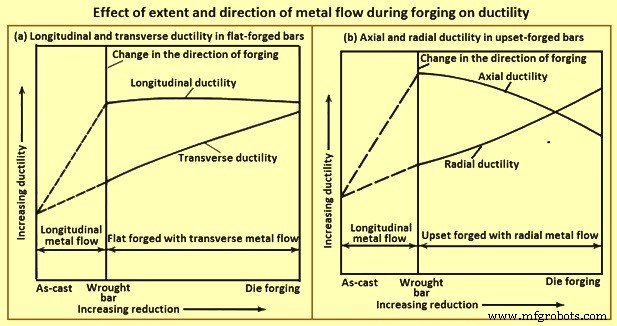
그림 4 단조강의 축방향 및 반경방향 연성에 대한 업셋 감소의 일반적인 영향
단조 구조 및 연성 – 재료 제어의 또 다른 측면은 최종 단조품이 설계의 기반이 되는 기계적 특성의 개발에 필요한 단조 구조를 달성하기에 충분한 소성 변형을 거쳤는지 확인합니다. 주조 제품이 단조 빌릿으로 분해되는 동안 약간의 소성 변형이 이루어지지만 폐쇄형 단조 공정 중에 훨씬 더 많이 발생합니다. 고강도 단조물에 대한 재료 제어는 단조품의 기계적 특성뿐만 아니라 단조용 빌렛의 기계적 특성을 결정해야 할 수 있습니다.
연성 또는 인성의 척도는 횡방향 인장 시험 샘플에서 얻은 면적 감소를 측정하여 결정됩니다. 동일한 강도 수준으로 열처리된 단조품에서 가져온 가로 및 세로 샘플로 해당 테스트를 수행하면 빌렛 스톡과 단조품의 기계적 특성을 비교하고 각각에 의해 기여하는 최종 단조 야금 구조의 비율을 추정할 수 있습니다.
연성 및 단조 감소량 – 재료 제어의 주요 목적은 완성된 단조에서 최적의 기계적 특성이 달성되도록 하는 것입니다. 단조에서 달성된 감소량은 주조 잉곳, 단조(압연) 막대 또는 빌렛 및 단조의 연성을 비교하는 그림 4에서 볼 수 있듯이 연성에 현저한 영향을 미칩니다. 그림 4(a)의 곡선은 단조 또는 빌렛이 금형에서 플랫 단조될 때 단조 감소의 증가가 종방향 연성에 영향을 미치지 않지만 횡방향 연성의 점진적인 증가를 초래함을 나타냅니다. 유사한 바 또는 빌렛이 다이에서 업셋 단조되면 단조 감소가 증가하면 축 방향 연성이 점진적으로 감소하고 반경 방향 연성이 점진적으로 증가합니다.
주조 잉곳의 연성은 화학적 조성, 용융 방식 및 잉곳 크기에 따라 다릅니다. 동일한 합금 조성의 강철 잉곳의 연성은 공기 용융 또는 진공 아크 재용해 강철에서 부어졌는지 여부에 따라 달라집니다. 특정 합금의 큰 잉곳으로 시작할 때 잉곳의 일부를 다양한 단조 감소량으로 다양한 빌렛 또는 막대 크기로 압연하는 것이 때때로 실용적입니다. 최소 감소량은 표준이 아니지만 2:1(주괴 단면적 대 빌렛 단면적의 비율) 미만인 경우는 거의 없습니다. 강철 잉곳에서 빌렛으로의 감소는 일반적으로 2:1보다 훨씬 큽니다. 대조적으로 일부 내열합금 단조품은 주괴에서 직접 단조됩니다.
종종, 잉곳의 전체 중량이 필요할 정도로 큰 단조용 빌렛을 준비하는 것은 실현 가능하지 않습니다. 단조 야금 구조로 대표되는 단조 감소량은 완성된 단조품에서 채취한 매크로 에칭 및 인장 테스트 샘플의 관찰 및 테스트에 의해 가장 잘 제어됩니다. 이 샘플을 통해 중요한 영역과 일반적으로 전체 단조품을 탐사할 수 있습니다. 그들은 필요에 따라 세로, 긴 가로 및 짧은 가로 곡물 방향에서 선택됩니다. 에칭 테스트를 통해 입자 흐름을 시각적으로 관찰할 수 있습니다. 기계적 테스트는 강도와 인성을 결정립 흐름과 연관시킵니다.
곡물 흐름 – 매크로 에칭은 입자 방향과 윤곽을 직접 관찰할 수 있게 하고 접힘, 랩 및 재진입 흐름을 감지하는 역할도 합니다. 적절한 샘플을 매크로 에칭하여 세로 방향, 긴 가로 방향 및 짧은 가로 방향으로 입자 흐름을 검사할 수 있습니다. Macro-etching은 또한 완전한 섹션, end-to-end 및 side-to-side의 평가와 거대 입자 크기의 균일성 검토를 허용합니다. 그림 2는 대표적인 단조품의 입자류를 나타낸 것이다.
입자 크기 및 미량 성분 – 현미경을 사용한 금속 조직 검사는 매크로 에칭에 의해 드러난 의심스러운 영역을 검사하고, 입자 크기를 측정하고, 미세 구성 요소의 성질과 양을 결정하는 데 가장 적합합니다.
피로 강도 – 피로 시험은 (i) 재료의 개발 또는 적격성 평가를 위한 작은 샘플의 실험실 테스트, (ii) 설계 개발을 위한 전체 구성요소 또는 하위 어셈블리의 실험실 테스트, 및 (iii) 서비스에서 지속적인 신뢰성을 보장하기 위해 현장에서 구성요소 또는 조립품을 감시합니다.
재료의 검증 또는 개발을 위한 작은 샘플의 실험실 피로 테스트는 표준 방법으로 수행됩니다. 테스트 샘플은 필요에 따라 압연 제품이나 폐쇄형 단조품에서 채취합니다. 표준 샘플은 단조 내의 많은 위치에서 선택을 허용하고 다양한 곡물 흐름 방향과 상관 관계가 있을 만큼 충분히 작습니다. 테스트는 일반적으로 공기 중에서 실온에서 수행되지만 더 높거나 낮은 온도와 특수 대기에서 테스트가 가능합니다.
구성 요소 또는 어셈블리의 분석에 소규모 실험실 피로 테스트를 적용하면 추가 변수가 발생합니다. 하나는 표면 상태의 영향입니다. 그림 5(a)의 곡선은 표면이 연마, 기계, 열간 압연 또는 단조되었는지 여부에 따라 강철 샘플의 피로 강도가 현저하게 변한다는 것을 보여줍니다. 테스트된 강은 269 HB ~ 285 HB로 열처리된 단조 저 합금강으로 인장 강도 876 MPa 및 항복 강도 696 MPa에 해당합니다. 샘플 준비에는 열처리 후에 샘플을 기계가공하고 연마해야 하며 열처리 전에 압연 또는 단조가 필요했습니다. 106 사이클의 피로 수명에 대해 피로 한계는 연마된 샘플의 경우 395MPa, 가공된 샘플의 경우 315MPa, 압연된 샘플의 경우 205MPa, 단조된 샘플의 경우 단 150MPa입니다.
그림 5(b)의 곡선은 인장 강도가 345 MPa에서 2,070 MPa 범위인 강에 적용되며 여러 테스트에서 얻은 근사치입니다. 965 MPa 인장 강도 수준에서 단조 또는 탈탄 샘플을 위한 샘플 준비에는 막대 스톡에서 거칠게 가공된 강이 포함되며, 가스 연소 머플로에서 20분에서 30분 동안 약 900°C로 가열되며 원본에서 매우 가볍게 스웨이징됩니다. 7.47 mm 직경에서 7.16 mm의 최종 직경까지, 공랭식. 열처리는 약 830℃의 염욕에서 45분 동안 오스테나이트화, 오일 담금질, 약 620℃에서 1시간 동안 공기 중 담금질 및 수냉 담금질로 이루어졌다. 단조 및 열처리로 약 0.064mm 깊이까지 탈탄된 표면이 생성되었습니다. 이 샘플은 106 사이클에서 약 310 MPa의 피로 강도를 나타냈지만 단조는 아니지만 기계가공 또는 연마되고 탈탄이 없는 샘플의 경우 470 MPa입니다. 탈탄은 열처리로 얻은 강도 수준을 낮춥니다. 표면 상태의 실험실 제어는 단조 부품의 대량 생산에서 복제하기 어렵습니다. 따라서 전체 크기 부품의 피로 강도는 표면 상태의 변화로 인해 작은 샘플의 피로 강도보다 넓은 범위에서 변합니다.
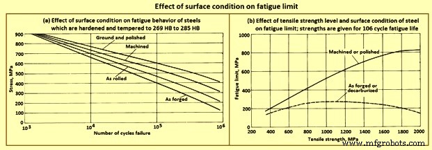
피로 한계에 대한 표면 상태의 영향
파단 인성 – 강철의 항복 강도보다 상당히 낮은 응력 수준에서 균열 전파의 결과로 단조 및 기타 구성요소의 취성 파괴는 파괴 특성 및 파괴 인성 평가 방법에 대한 광범위한 연구로 이어졌습니다. 이러한 연구의 결과는 특히 재료 제어 표준의 기반이 될 수 있는 파괴 인성 평가 시험 개발과 관련하여 재료 제어에 매우 중요합니다.
In the area of laboratory tests and analytical techniques, major emphasis has been placed on the development of dependable methods for evaluating the strength of steels which contain cracks or crack like defects. Specifically, interest has centered on methods for determining plane-strain fracture toughness. Forged components are evaluated by testing small samples removed from selected locations on the forging which are representative of the various grain directions.
One test procedure comprises the bend testing of the notched and fatigue-cracked samples in a neutral environment. The objective of this test is to get a lower limiting value of fracture toughness which can be used to estimate the relationship between stress and defect size in a metal under service conditions in which high constraint is expected. In the test procedure referred to, a test sample with a chevron notch is suitably pre-cracked in fatigue. It is then tested in a bend test fixture provided with support rolls which rotate and move apart slightly to permit rolling contact and virtually eliminate the friction effect. The sample is subjected to three-point bending, and the imposed load versus displacement change across the notch is recorded on an autographic recorder. Fracture toughness is rated by a calculated parameter, the critical stress intensity.
End-grain exposure – Lowered resistance to stress-corrosion cracking in the long-transverse and short-transverse directions is related to the end-grain exposure. A long, narrow test sample sectioned so that the grain is parallel to the longitudinal axis of the sample has no exposed end grain, except at the extreme ends, which are not subjected to the loading. In contrast, a corresponding sample cut in the transverse direction has end-grain exposure at all points along its length. End grain is especially pronounced in the short-transverse direction on die forgings designed with a flash line. Consequently, forged components designed to reduce or eliminate end grain have better resistance to stress-corrosion cracking.
Residual stress – The sustained tensile stress at the surface of a forging which contributes to stress-corrosion cracking is the total of applied and residual stresses. When the residual stress constitutes a significant percentage of the total stress, it is to be reduced or eliminated. Common sources of residual tensile stresses include quenching, machining, and poor fit in assembly. Each can be suitably modified to reduce or eliminate tensile stresses, especially those present in an exposed surface. As an example, drastic quenching places the surface of a heat-treatable alloy in a state of compression and the core in a state of tension. Furthermore, the compressed surface can be entirely removed during rough machining, exposing the tension-stressed core material. This hazard can be avoided by quenching after, rather than before, rough machining. In some applications, a surface in tension is placed in compression by shot peening.
Hydrogen-stress cracking occurs without corrosion. Hence, its initiation is not confined to exterior surfaces in contact with a corrosive medium. It can start at any suitable nucleus, such as an inclusion or void, as well as at a surface notch or other irregularity. Hydrogen-stress cracking at the interior is described as hydrogen embrittlement or hydrogen flaking. Hydrogen-stress cracking has been observed, studied, and brought under control in most high-strength steels. The modern practice of vacuum melting can reduce residual hydrogen to negligible amounts. A hydrogen content of 3 ppm to 6 ppm in air-melted steel can be readily lowered to 0.6 ppm to 1 ppm by vacuum arc remelting. Provided that the initial hydrogen content of the steel is acceptably low, material control procedures are to ensure that hydrogen pickup is avoided in all subsequent processing, including forging, heat treating, hot salt bath descaling, pickling, and plating. During forging, steels develop a surface scale and a decarburized surface layer, both of which are subsequently removed by grit blasting and machining. Unless the steel is acid pickled, there is no possibility of hydrogen pickup.
Many of the critical parts made from steel forgings are protected by a coating of cadmium. Steel parts heat treated to strength levels higher than 1,655 MPa are especially sensitive to hydrogen pickup, in case they are coated with cadmium, the coating is deposited in vacuum. Parts heat treated to strength levels lower than 1,655 MPa can be cadmium plated electrolytically, provided that a titanium-containing plating bath is used and the parts are subsequently baked at around 190 deg C for 12 hours.
Mechanical properties – A major advantage of shaping metal parts by rolling, forging, or extrusion stems from the opportunities such processes offer the designer with respect to the control of grain flow. The strength of these and similar wrought products is almost always greatest in the longitudinal direction (or equivalent) of grain flow, and the maximum load-carrying ability in the finished part is achieved by providing a grain-flow pattern parallel to the direction of the major applied service loads when, in addition, sound, dense, good-quality metal of sufficiently fine grain size has been produced throughout.
Grain flow and anisotropy – Steel which is rolled, forged, or extruded develops and retains a fiber like grain structure aligned in the principal direction of working. This characteristic becomes visible on external and sectional surfaces of wrought products when the surfaces are suitably prepared and etched. The fibers are the result of elongation of the micro-structural constituents of the steel in the direction of working. Hence, the phrase ‘direction of grain flow’ is normally used to describe the dominant direction of these fibers within wrought metal products.
In wrought steel, the direction of grain flow is also evidenced by measurements of mechanical properties. Strength and ductility are almost always greater in the direction parallel to that of working. The characteristic of showing different strength and ductility values with respect to the direction of working is referred to as mechanical anisotropy and is exploited in the design of wrought products. Although the best properties in wrought steels are most frequently the longitudinal (or equivalent), properties in other directions can yet be superior to those in products not wrought, that is, in cast ingots or in forging stock taken from a lightly worked ingot.
Rectangular sections show anisotropy among all the three principal directions i.e. longitudinal, long transverse, and short transverse. A design which employs a rectangular section involves the properties in all these directions, not just the longitudinal. Hence, the longitudinal, long-transverse, and short-transverse service loads of rectangular sections are analyzed separately.
Anisotropy in high strength steel – Although all wrought steels are mechanically anisotropic, the effects of anisotropy on mechanical properties vary among different metals and alloys. For example, a vacuum-melted steel of a given composition is generally less mechanically anisotropic than a conventionally killed, air-melted steel of the same composition. Response to etching to reveal the grain flow characteristic of anisotropy also varies. Steels with poor corrosion resistance are readily etched, while those with good corrosion resistance need more corrosive etchants and extended etching times to reveal grain flow. In general, fatigue properties are markedly affected by the relation of flow-line direction to direction of stresses from applied loads. When flow lines are perpendicular to load stresses, a stress-raising effect is produced.
Forging lubricants
For many years, oil-graphite mixtures have normally being used as lubricants for forging carbon and alloy steels. Recent advances in lubricant technology, however, have resulted in new types of lubricants, including water/graphite mixtures and water-base synthetic lubricants. Each of the normally used lubricants has advantages as well as limitations (Tab 2) which is required to be balanced against process requirements.
| Tab 2 Advantages and limitations of the main lubricants used for hot forging of steels | |||
| Sl. No. | Type of lubricant | Advantages | Limitations |
| 1 | Water-base micro-graphite | Eliminates smoke and fire; provides die cooling; is easily extended with water | Must be applied by spraying for best results |
| 2 | Water-base synthetic | Eliminates smoke and fire; is cleaner than oils or water-base graphite; aids die cooling; is easily diluted, and needs no agitation after initial mixing; reduces clogging of spray equipment; does not transfer dark pigment to part | Must be sprayed; lacks the lubricity of graphite for severe forging operations |
| 3 | Oil-base graphite | Fluid film lends itself to either spray or swab application; has good performance over a wide temperature range (upto 540 deg C). | Generates smoke, fire, and noxious odours; explosive nature may shorten die life; has potentially serious health and safety implications for workers |
Selection criteria – Lubricant selection for forging is based on several factors, including forging temperature, die temperature, forging equipment, method of lubricant application, complexity of the part being forged and environmental and safety considerations. At normal hot-forging temperatures for carbon and alloy steels, water-base graphite lubricants are used almost exclusively, although some hammer shops still employ oil-base graphite.
The most common warm-forming temperature range for carbon and alloy steels is 540 deg C to 870 deg C. Because of the severity of forging conditions at these temperatures, billet coatings are often used in conjunction with die lubricants. The billet coatings used include graphite in a fluid carrier or water-base coatings used in conjunction with phosphate conversion coating of the work piece. For still lower forging temperatures (less than around 400 deg C, molybdenum disulphide has a greater load-carrying capacity than does graphite. Molybdenum disulphide can either be applied in solid form or dispersed in a fluid carrier.
Heat treatment of carbon and alloy steel forgings
Normally steel forgings are specified based upon one of four man conditions namely (i) as forged with no further thermal processing, (ii) heat treated for machinability, (iii) heat treated for final mechanical / physical properties, or (iv) special heat treatment to enhance dimensional stability, particularly in more complex part configurations.
As forged with no further thermal processing – Although the vast majority of steel forgings are heat treated before use, a large tonnage of low carbon steel (0.1 % to 0.25 % C) is used in the as-forged condition. In such forgings, machinability is good, and little is gained in terms of strength by heat treatment. In fact, a number of widely used specifications permit this economic option. It is also interesting to note that, compared to the properties produced by normalizing, strength and machinability are slightly better, which is most likely attributable to the fact that grain size is somewhat coarser than in the normalized condition.
Heat treated for machinability – When a finished machined component is to be produced from a roughly dimensioned forging, machinability becomes a vital consideration to optimize tool life, increase productivity, or both. The specification or forging drawing can specify the heat treatment. However, when specifications give only maximum hardness or micro-structural specifications, the most economical and effective thermal cycle is to be selected. Available heat treatments include full anneal, spheroidize anneal, sub-critical anneal, normalize, or normalize and temper. The heat treatment chosen depends on the steel composition and the machine operations to be performed. Some steel grades are inherently soft while others become quite hard in cooling from the finishing temperature after hot forging. Some type of annealing is usually required or specified to improve machinability.
Heat treated for final mechanical / physical properties – Normalizing or normalizing and tempering can produce the needed minimum hardness and minimum ultimate tensile strength. However, for most steels, a hardening (austenitize) and quenching (in oil, water, or some other medium, depending on section size and hardenability) cycle is employed, followed by tempering to produce the proper hardness, strength, ductility, and impact properties. For steel forgings to be heat treated above the 1,035 MPa strength level and having section size variations, it is general practice to normalize before austenitizing to produce a uniform grain size and minimize internal residual stresses. In some instances, it is normal practice to use the heat for forging as the austenitizing cycle and to quench at the forge unit. The forging is then tempered to complete the heat treat cycle. Although there are obvious limitations to this procedure, definite economies are possible when the procedure is applicable (usually for symmetrical shapes of carbon steels which need little final machining).
Special heat treatment to enhance dimensional stability – Special heat treatments, particularly in more complex part configurations, are sometimes used to control dimensional distortion, relieve residual stresses before or after machining operations, avoid quench cracking, or prevent thermal shock or surface (case) hardening. Although most of the heat-treating cycles can apply, very specific treatments can be needed. Such treatments normally apply to complex forging configurations with adjacent differences in section thickness, or to very high hardenability steels and alloys. When stability of critically dimensioned finished parts permits only light machining of the forging after heat treatment to final properties, special treatments are available, including mar-quenching (mar-tempering), stress relieving, and multiple tempering.
Many applications, such as crankshafts, camshafts, gears, forged rolls, rings, certain bearings, and other machinery components, need increased surface hardness for wear resistance. The important surfaces are normally hardened after machining by flame or induction hardening, carburizing, carbo-nitriding, or nitriding. These processes are listed in the approximate order of increasing cost and decreasing maximum temperature. The latter consideration is important in that dimensional distortion normally decreases with decreasing temperature. This is particularly true of nitriding, which is usually performed below the tempering temperature for the steel used in the forging.
Micro-alloyed forging steels
Micro-alloying (the use of small amounts of elements such as vanadium and niobium to strengthen steels) has been in practice since the 1960s to control the micro-structure and properties of low carbon steels. Most of the early developments have been related to plate and sheet products in which micro-alloy precipitation, controlled rolling, and modern steelmaking technology combined to increase strength significantly relative to that of low carbon steels.
The application of micro-alloying technology to forging steels has lagged behind that of flat-rolled products because of the different property requirements and thermo-mechanical processing of forging steels. Forging steels are normally used in applications in which high strength, fatigue resistance, and wear resistance are needed. These requirements are most often filled by medium carbon steels. Thus, the development of micro-alloyed forging steels has been based around the grades containing 0.3 % to 0.5 % C.
The driving force behind the development of micro-alloyed forging steels has been the need to reduce the production costs. This is accomplished in these materials by means of a simplified thermo-mechanical treatment (that is, a controlled cooling following hot forging) which achieves the desired properties without the separate quenching and tempering treatments required by conventional carbon and alloy steels. In Fig 6, the processing sequence for conventional (quenched and tempered) steels is compared with the micro-alloyed steel-forging process.
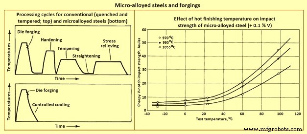
Fig 6 Micro-alloyed steels and forgings
Effects of micro-alloying elements
Carbon – Most of the micro-alloyed steels developed for forging have carbon contents ranging from 0.3 % to 0.5 %, which is high enough to form a large amount of pearlite. The pearlite is responsible for substantial strengthening. This level of carbon also decreases the solubility of the micro-alloying constituents in austenite.
Niobium, vanadium, and titanium – Formation of carbo-nitride precipitates is the other major strengthening mechanism of micro-alloyed forging steels. Vanadium, in amounts ranging from 0.05 % to 0.2 %, is the most common micro-alloying addition used in forging steels. Niobium and titanium enhance strength and toughness by providing control of austenite grain size. Frequently niobium is used in combination with vanadium to achieve the benefits of austenite grain size control (from niobium) and carbo-nitride precipitation (from vanadium).
Manganese – Manganese is used in relatively large amounts (1.4 % to 1.5 %) in many micro-alloyed forging steels. It tends to reduce the cementite plate thickness while maintaining the inter-lamellar spacing of pearlite developed. Hence, high manganese levels require lower carbon contents to retain the large amounts of pearlite required for high hardness. Manganese also provides substantial solid solution strengthening, enhances the solubility of vanadium carbonitrides, and lowers the solvus temperature for these phases.
Silicon – The silicon content of most commercial micro-alloyed forging steels is around 0.3 %. Some grades contain upto 0.7 %. Higher silicon contents are associated with significantly higher toughness, apparently because of an increased amount of ferrite relative to that formed in ferrite-pearlite steels with lower silicon contents.
Sulphur – Many micro-alloyed forging steels, particularly those needed for use in automotive forgings in which machinability is critical, have relatively high sulphur contents. The higher sulphur contents contribute to their machinability, which is comparable to that of quenched and tempered steels.
Aluminum and nitrogen – As in hardenable fine-grain steels, aluminum is important for austenite grain size control in micro-alloyed steels. The mechanism of aluminum grain size control is the formation of aluminum nitride particles. It has been shown that nitrogen is the major interstitial component of vanadium carbo-nitride. For this reason, moderate to high nitrogen contents are needed in vanadium containing micro-alloyed steels to promote effective precipitate strengthening.
Controlled Forging
The concept of grain size control has been used for many years in the production of flat rolled products. Particularly in plate rolling, the ability to increase austenite recrystallization temperature using small niobium additions is well known. The process used to produce these steels is usually referred to as controlled rolling. The benefits of austenite grain size control are not, of course, limited to flat rolled products. Although the higher finishing temperatures needed for rolling of bars limit the usefulness of this approach to micro-structural control, finishing temperatures for micro-alloyed bar steels is nonetheless to be controlled.
It has been shown that, although strength is not significantly affected by finishing temperature, toughness of vanadium-containing micro-alloyed steels decreases with increasing finishing temperature. This effect is shown in Fig 6, which compares Charpy V-notch impact strength for a micro-alloyed steel finished at three temperatures. This detrimental effect of a high finishing temperature on impact toughness also carries over to forging operations, that is, the lower the finish temperature in forging, the higher the resulting toughness, and vice versa. After extensive testing, it has been shown that the finishing temperature for forging if reduced to near 1000 deg C, results in impact properties equal to or better than those of hot rolled bar. It is also shown that rapid induction preheating is beneficial for micro-alloyed forging steels, and that cost savings of 10 % (for standard micro-alloyed forgings) to 20 % (for resulphurized grades) are possible.
Lower finishing temperatures, however, take their toll in terms of higher required forging pressures (and thus higher machine capacities needed) and increased die wear. The improved toughness resulting from lower finishing temperatures, as well as any cost savings which can be achieved as a result of the elimination of heat treatment, is to be weighed against the cost increases caused by these factors.
Micro-alloyed cold heading steels -Steels used in the production of high-strength fasteners by cold heading have been earlier produced from quenched and tempered alloy steels. To obtain sufficient strength with adequate ductility needed six processing steps. Recent developments have led to the use of micro-alloyed niobium-boron steels which need no heat treatment. These steels make use of niobium and boron additions to develop bainitic structures with high work-hardening rates. In most cases they use the deformation of cold heading to achieve the required strength levels without heat treatment.
제조공정
카본 아크 용접이란 무엇입니까? 탄소 아크 용접(CAW)은 비소모성 탄소(흑연) 전극과 공작물 사이의 아크로 금속을 가열하여 금속의 유착을 생성하는 공정입니다. 탄소-아크 용접에서 탄소 전극은 전극과 접합되는 재료 사이에 전기 아크를 생성하는 데 사용됩니다. 이것은 개발된 최초의 아크 용접 공정이었지만 오늘날에는 트윈 탄소 아크 용접 및 기타 변형으로 대체되어 많은 응용 분야에 사용되지 않습니다. 아크 용접의 목적은 분리된 금속 사이에 결합을 형성하는 것입니다. 이 아크는 3,000°C를 초과하는 온도를 생성합니다. 이 온도에
탄소 섬유 (CF)는 직경이 약 5-10마이크로미터이고 대부분 탄소 원자로 구성된 섬유입니다. 탄소 섬유에는 몇 가지 장점이 있습니다. 높은 강성 , 높은 인장 강도 , 저중량 그리고 높은 내화학성 . 이 게시물을 읽고 나면 주요 분류를 알게 될 것입니다. 탄소 섬유의 원료 자세한 제조 프로세스에 대해 알아보세요. 즉, 탄소 섬유 제품의 품질을 빠르게 구별하고 전체 제조 공정을 보다 효율적으로 파악할 수 있습니다. 1. 탄소 섬유의 일반 분류 아. 인장 계수 기준 인장 계수 탄소 섬유를 분류하는 핵심 기준은 섬유입