verilog


디지털 전자 제품에서 시프트 레지스터 출력 핀이 q인 플립플롭의 캐스케이드입니다. 한 플롭의 데이터 입력 핀(d)이 다음 플롭에 연결됩니다. 모든 플롭이 동일한 클럭에서 작동하기 때문에 시프트 레지스터에 저장된 비트 어레이는 한 위치만큼 이동합니다. 예를 들어, 5비트 오른쪽 시프트 레지스터의 초기 값이 10110이고 시프트 레지스터에 대한 입력이 0에 연결되어 있으면 다음 패턴은 01011이 되고 다음 패턴은 00101이 됩니다.
<노스크립트>
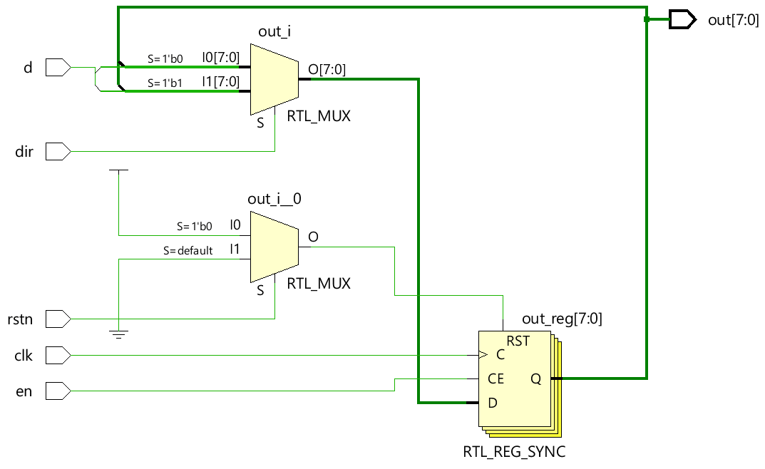
이 시프트 레지스터 디자인에는 5개의 입력과 1개의 n비트 출력이 있으며 디자인은 parameter을 사용하여 매개변수화됩니다. 시프트 레지스터의 너비를 나타내는 MSB. n이 4이면 4비트 시프트 레지스터가 됩니다. n이 8이면 8비트 시프트 레지스터가 됩니다.
이 시프트 레지스터에는 몇 가지 주요 기능이 있습니다.
module shift_reg  #(parameter MSB=8) (  input d,                      // Declare input for data to the first flop in the shift register
                                        input clk,                    // Declare input for clock to all flops in the shift register
                                        input en,                     // Declare input for enable to switch the shift register on/off
                                        input dir,                    // Declare input to shift in either left or right direction
                                        input rstn,                   // Declare input to reset the register to a default value
                                        output reg [MSB-1:0] out);    // Declare output to read out the current value of all flops in this register


   // This always block will "always" be triggered on the rising edge of clock
   // Once it enters the block, it will first check to see if reset is 0 and if yes then reset register
   // If no, then check to see if the shift register is enabled
   // If no => maintain previous output. If yes, then shift based on the requested direction
   always @ (posedge clk)
      if (!rstn)
         out <= 0;
      else begin
         if (en)
            case (dir)
               0 :  out <= {out[MSB-2:0], d};
               1 :  out <= {d, out[MSB-1:1]};
            endcase
         else
            out <= out;
      end
endmodule

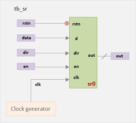
테스트 벤치는 이 시프트 레지스터의 기능을 확인하는 데 사용됩니다. 디자인은 상위 module로 인스턴스화됩니다. 입력은 다른 값으로 구동됩니다. 각 입력에 대한 설계 동작은 출력 핀 출력에서 관찰할 수 있습니다.

module tb_sr;
   parameter MSB = 16;        // [Optional] Declare a parameter to represent number of bits in shift register

   reg data;                  // Declare a variable to drive d-input of design
   reg clk;                   // Declare a variable to drive clock to the design
   reg en;                    // Declare a variable to drive enable to the design
   reg dir;                   // Declare a variable to drive direction of shift registe
   reg rstn;                  // Declare a variable to drive reset to the design
   wire [MSB-1:0] out;        // Declare a wire to capture output from the design

   // Instantiate design (16-bit shift register) by passing MSB and connect with TB signals
   shift_reg  #(MSB) sr0  (  .d (data),
                             .clk (clk),
                             .en (en),
                             .dir (dir),
                             .rstn (rstn),
                             .out (out));

   // Generate clock time period = 20ns, freq => 50MHz
   always #10 clk = ~clk;

   // Initialize variables to default values at time 0
   initial begin
      clk <= 0;
      en <= 0;
      dir <= 0;
      rstn <= 0;
      data <= 'h1;
   end

   // Drive main stimulus to the design to verify if this works
   initial begin

      // 1. Apply reset and deassert reset after some time
      rstn <= 0;
      #20 rstn <= 1;
          en <= 1;

	  // 2. For 7 clocks, drive alternate values to data pin
      repeat (7) @ (posedge clk)
         data <= ~data;

     // 4. Shift direction and drive alternate value to data pin for another 7 clocks
      #10 dir <= 1;
      repeat (7) @ (posedge clk)
         data <= ~data;

      // 5. Drive nothing for next 7 clocks, allow shift register to simply shift based on dir
      repeat (7) @ (posedge clk);

      // 6. Finish the simulation
      $finish;
   end

   // Monitor values of these variables and print them into the logfile for debug
   initial
      $monitor ("rstn=%0b data=%b, en=%0b, dir=%0b, out=%b", rstn, data, en, dir, out);
endmodule
시프트 레지스터가 활성화된 시간은 아래 주어진 로그에서 녹색으로 강조 표시됩니다. 방향이 바뀌는 시간은 노란색으로 강조 표시됩니다. 데이터 입력 핀이 일정하게 유지되는 시간은 파란색으로 강조 표시됩니다.
시뮬레이션 로그ncsim> run rstn=0 data=1, en=0, dir=0, out=xxxxxxxxxxxxxxxx rstn=0 data=1, en=0, dir=0, out=0000000000000000 rstn=1 data=1, en=1, dir=0, out=0000000000000000 rstn=1 data=0, en=1, dir=0, out=0000000000000001 rstn=1 data=1, en=1, dir=0, out=0000000000000010 rstn=1 data=0, en=1, dir=0, out=0000000000000101 rstn=1 data=1, en=1, dir=0, out=0000000000001010 rstn=1 data=0, en=1, dir=0, out=0000000000010101 rstn=1 data=1, en=1, dir=0, out=0000000000101010 rstn=1 data=0, en=1, dir=0, out=0000000001010101 rstn=1 data=0, en=1, dir=1, out=0000000001010101 rstn=1 data=1, en=1, dir=1, out=0000000000101010 rstn=1 data=0, en=1, dir=1, out=1000000000010101 rstn=1 data=1, en=1, dir=1, out=0100000000001010 rstn=1 data=0, en=1, dir=1, out=1010000000000101 rstn=1 data=1, en=1, dir=1, out=0101000000000010 rstn=1 data=0, en=1, dir=1, out=1010100000000001 rstn=1 data=1, en=1, dir=1, out=0101010000000000 rstn=1 data=1, en=1, dir=1, out=1010101000000000 rstn=1 data=1, en=1, dir=1, out=1101010100000000 rstn=1 data=1, en=1, dir=1, out=1110101010000000 rstn=1 data=1, en=1, dir=1, out=1111010101000000 rstn=1 data=1, en=1, dir=1, out=1111101010100000 rstn=1 data=1, en=1, dir=1, out=1111110101010000 Simulation complete via $finish(1) at time 430 NS + 0<노스크립트>

verilog
Verilog는 하드웨어 설명 언어이며 설계자가 RTL 설계를 시뮬레이션하여 논리 게이트로 변환할 필요가 없습니다. 시뮬레이션이 필요한 이유는 무엇입니까? 시뮬레이션은 RTL 코드가 의도한 대로 동작하는지 확인하기 위해 다른 시간에 다른 입력 자극을 설계에 적용하는 기술입니다. 기본적으로 시뮬레이션은 설계의 견고성을 검증하기 위해 잘 따라야 하는 기술입니다. 또한 가공된 칩이 실제 세계에서 사용되는 방식과 다양한 입력에 반응하는 방식과 유사합니다. 예를 들어, 위의 디자인은 출력 pe 보여진 바와 같이. 시뮬레이션을 통해
디지털 전자 제품에서 시프트 레지스터 출력 핀이 q인 플립플롭의 캐스케이드입니다. 한 플롭의 데이터 입력 핀(d)이 다음 플롭에 연결됩니다. 모든 플롭이 동일한 클럭에서 작동하기 때문에 시프트 레지스터에 저장된 비트 어레이는 한 위치만큼 이동합니다. 예를 들어, 5비트 오른쪽 시프트 레지스터의 초기 값이 10110이고 시프트 레지스터에 대한 입력이 0에 연결되어 있으면 다음 패턴은 01011이 되고 다음 패턴은 00101이 됩니다. 디자인 이 시프트 레지스터 디자인에는 5개의 입력과 1개의 n비트 출력이 있으며 디자인은 par