

제조공정

산업 제조
<메인 클래스="사이트 메인" id="메인">
이 프로젝트에서는 Arduino 기반 DIY 자판기를 만드는 방법을 배웁니다. MDF 기판을 자르고 조립하는 것부터 모든 전자 부품을 연결하고 Arduino 코드를 작성하는 것까지 만드는 전체 과정을 보여 드리겠습니다.
다음 비디오를 보거나 아래에 작성된 튜토리얼을 읽을 수 있습니다.
자판기는 4개의 연속 회전 서보 모터로 제어되는 4개의 배출 장치, 스테퍼 모터로 제어되는 캐리어 시스템, LCD, 품목 선택을 위한 4개의 버튼 및 동전 감지기로 구성되어 있습니다.
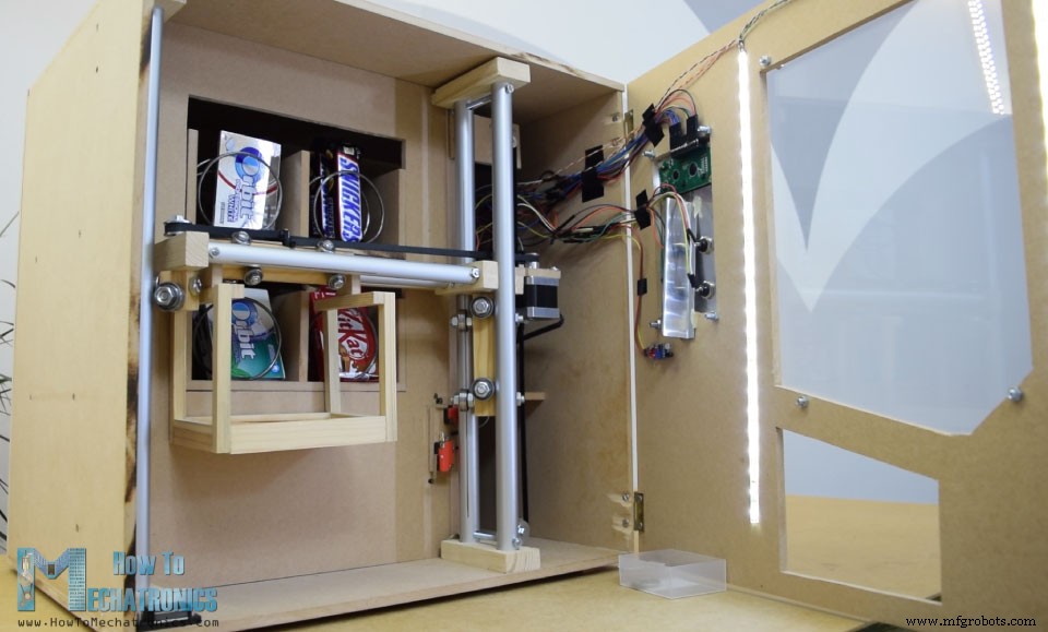
당신은 이제 아이템 캐리어가 이 자판기에 그다지 유용하지 않다고 생각할 수도 있고, 아마도 당신이 옳을 것입니다. 하지만 여기서 제 생각은 이 프로젝트를 더 흥미롭거나 조금 더 복잡하게 만들어 더 많은 새로운 것을 배울 수 있도록 하는 것이었습니다. 저는 이 프로젝트 아이디어가 마지막 해 프로젝트로 하나를 구축하려는 전자공학 또는 메카트로닉스 학생들과 Arduino 매니아에게 매우 유용할 수 있다고 생각합니다.
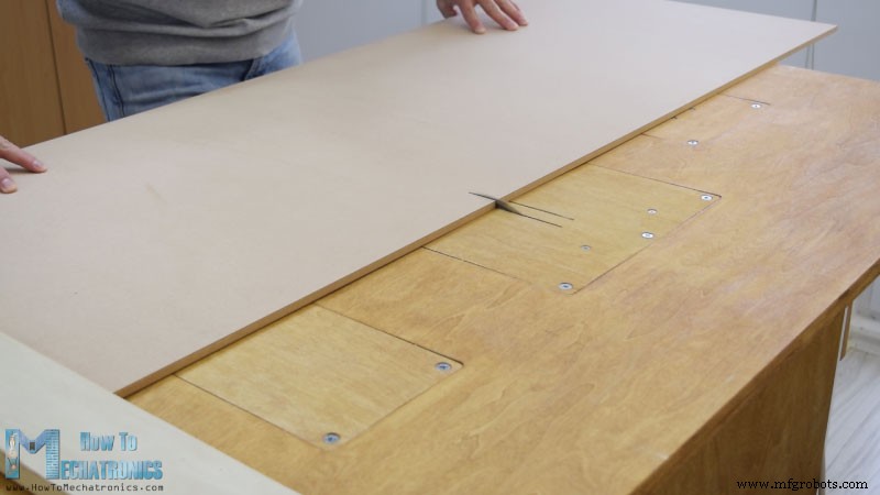
8mm 눈금 MDF 보드를 크기에 맞게 자르는 것으로 시작했습니다.
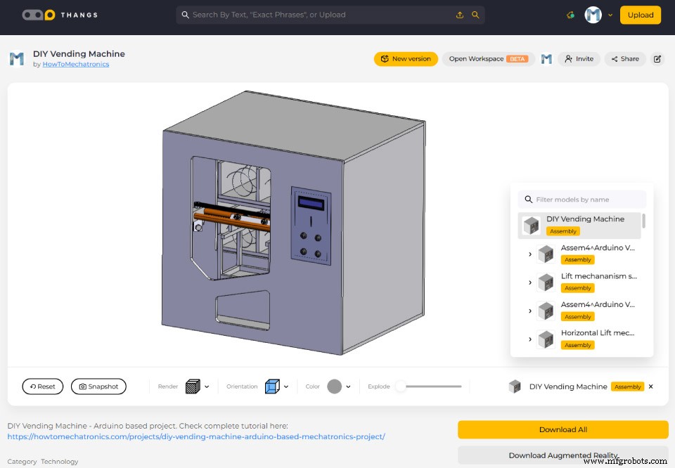
이전에 모든 측정값을 얻은 기계의 3D 모델을 만든 적이 있습니다.
이 3D 모델을 찾아 다운로드할 수 있을 뿐만 아니라 Thangs의 브라우저에서 탐색할 수도 있습니다.
MDF를 절단하기 위해 원형 톱을 사용했습니다. 사실 이것은 내 파트너 Marija가 만든 원형 톱, 라우터 및 퍼즐이 있는 수제 작업대이며 그녀의 YouTube 채널 Creativity Hero에 DIY 비디오가 있습니다.
원형 톱을 사용하여 모든 패널을 자른 후 거꾸로 된 퍼즐을 사용하여 일부 패널에 구멍을 계속 만들었습니다.
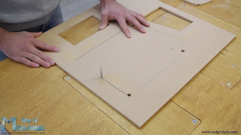
실제로 원형톱이 없는 경우에는 이전 단계에서도 퍼즐을 사용할 수 있습니다. 나는 또한 여러 컷이 있는 작은 부분을 자르기 위해 퍼즐을 사용했습니다. 단, 위험한 기계이므로 사용에 주의가 필요합니다.
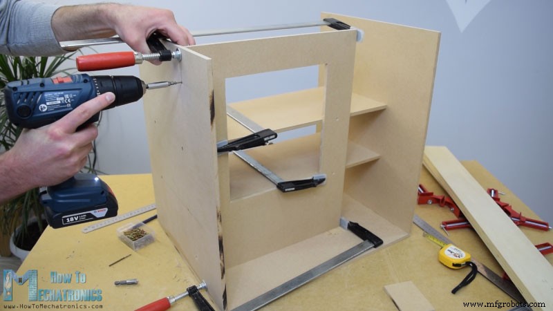
모든 MDF 부품이 준비되면 목재 접착제와 나사를 사용하여 조립을 시작했습니다. 패널을 고정하기 위해 90도 각도 클램프를 사용했습니다. 무선 드릴을 사용하여 먼저 파일럿 구멍을 만든 다음 카운터 싱크를 만들고 3mm 나사를 제자리에 조였습니다. 모든 패널을 조립하는 데 동일한 방법을 사용했으며 일부 패널에는 F 클램프도 사용했습니다.
어셈블리의 이 시점에서 레일 시스템을 계속 만들 것입니다. 그 목적을 위해 나는 금속 손 톱을 사용하여 크기에 맞게 자른 알루미늄 튜브를 사용하고 있습니다. 수평 레일의 경우 튜브 직경은 16mm이고 수직 레일의 경우 직경은 20mm입니다. 단단한 18mm 목재 보드에 Forstner 비트를 사용하여 튜브용 슬롯을 만든 다음 튜브를 부착했습니다.
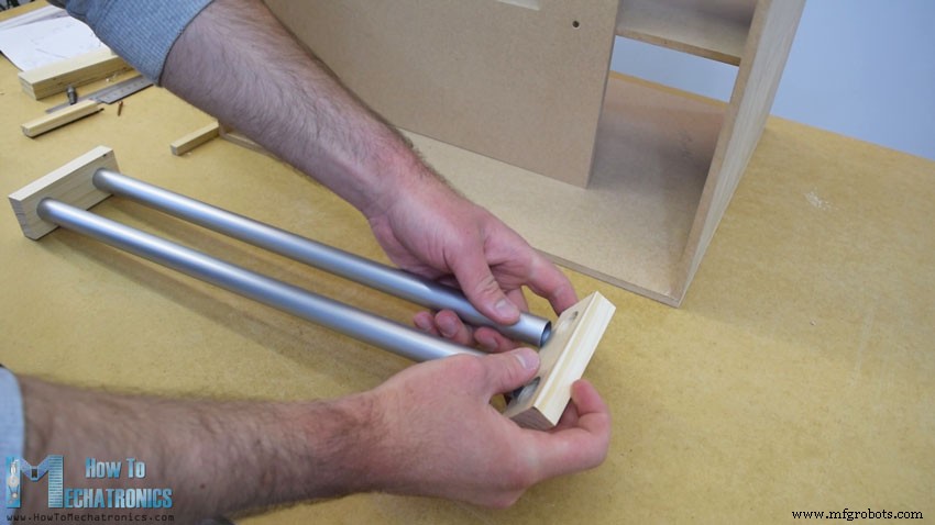
수평 레일은 27cm 길이의 튜브 2개로 구성되고 수직 레일은 45cm 길이의 튜브 3개로 구성됩니다.
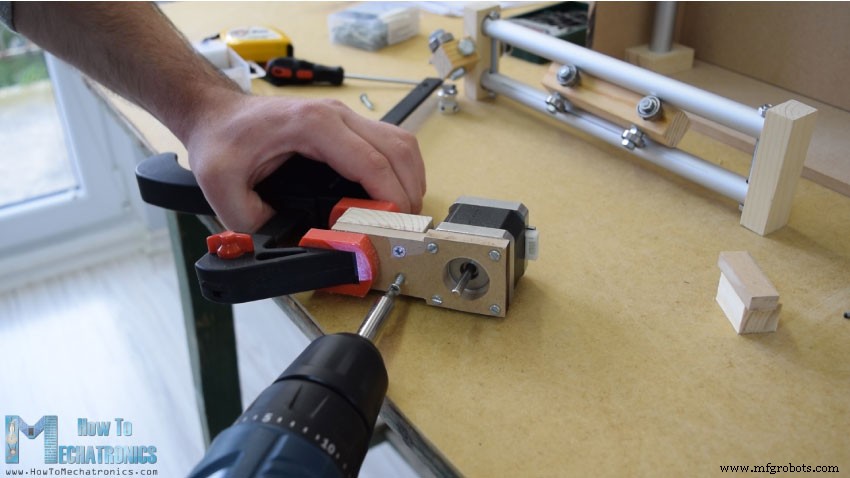
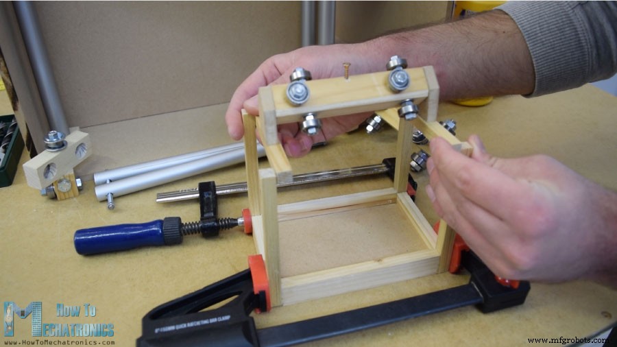
다음은 슬라이더이고 제가 만든 방법은 다음과 같습니다. 8mm 구멍을 뚫은 21 x 21 cm 나무 판자를 사용했습니다.
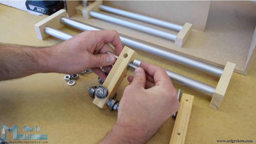
그런 다음 이 구멍을 통해 8mm 나사 막대를 삽입하고 와셔와 너트를 사용하여 22mm 베어링을 고정했습니다. 수평 슬라이더의 경우 동일한 방법을 사용했지만 외경이 16mm인 더 작은 베어링을 사용했습니다.
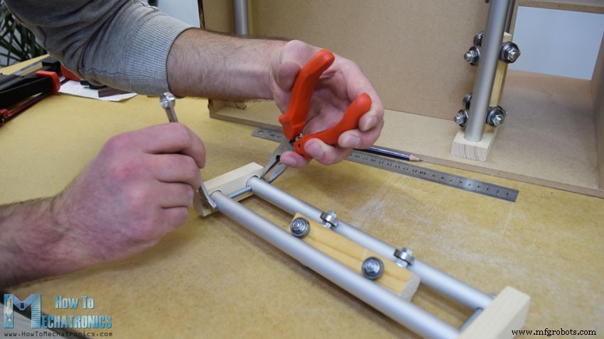
튜브 레일 사이에 슬라이더를 삽입한 후 슬라이더가 약간 느슨하다는 것을 알았습니다. 이 문제를 해결하기 위해 두 레일 사이의 거리를 줄여야 했습니다. 그래서 먼저 튜브 슬롯을 확장한 다음 튜브를 통해 수직 슬롯을 만들고 마지막으로 나사 막대를 사용하여 두 튜브 레일을 서로 더 가깝게 고정했습니다. 그 후 슬라이더가 더 이상 헐거워지지 않고 제대로 작동했습니다.
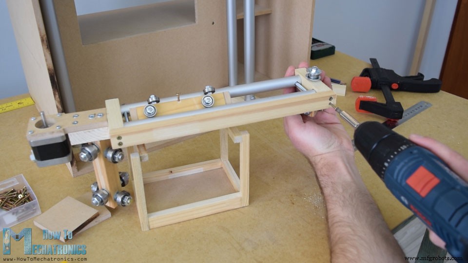
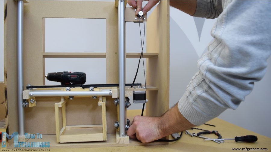
그러나 이 시점에서 다른 요소를 추가하기 위해 레일을 분해해야 했습니다. 먼저 수평 타이밍 벨트용 풀리를 부착할 레일 왼쪽에 5mm 볼트를 추가하고 왼쪽 수직 레일에서 미끄러질 베어링 2개를 추가로 추가했습니다.
레일의 다른 쪽 오른쪽에는 수평 이동을 위해 스테퍼 모터를 부착해야 했습니다. 먼저 8mm MDF 보드에 모터를 고정한 다음 지지용 나무 조각을 추가하고 슬롯 부분도 고정했습니다. 마지막으로 목제 풀과 나사 2개를 사용하여 이 전체 어셈블리를 수직 슬라이더에 부착했습니다.
다음으로 수평 슬라이더에 컨테이너를 계속 추가했습니다. 그 목적을 위해 나는 나무 접착제를 사용하여 함께 결합하는 작은 나무 조각을 사용했습니다. 이 작업이 완료되면 철도 시스템을 조립할 준비가 되었습니다. 레일 슬롯에 약간의 에폭시를 사용하고 레일 측면에 목재 보드를 추가하여 전체 레일 시스템을 더 단단하게 만들었습니다.
다음 단계에서는 수직 레일 사이에 어셈블리를 삽입하고 제자리에 고정했습니다. 슬라이더와 레일 시스템의 최종 결과는 훌륭하게 작동하는 것으로 나타났습니다.
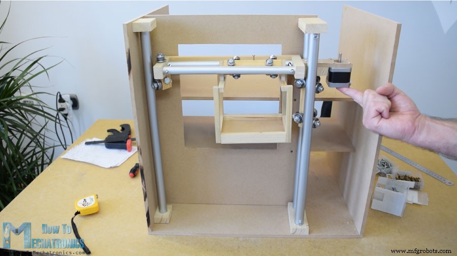
수평 타이밍 벨트를 계속 설치했습니다. 필요한 길이를 측정하고 크기에 맞게 자른 다음 지퍼 타이를 사용하여 슬라이더에 고정했습니다. 수직 슬라이더의 경우 MDF 조각과 일부 볼트를 사용하여 기계 상단에 스테퍼 모터를 부착했습니다. 하단에 풀리를 연결하고 타이밍 벨트도 같은 방법으로 장착했습니다.
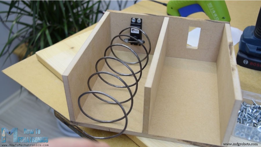
다음으로 아이템 배출부로 이동했습니다. 직경 7cm의 스프레이 페인트 캔에 3mm 진드기의 금속 와이어를 감아 나선형 코일을 만들었습니다.
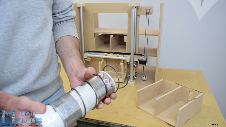
그 후 글루건을 이용하여 연속 회전 서보 모터에 고정했습니다.
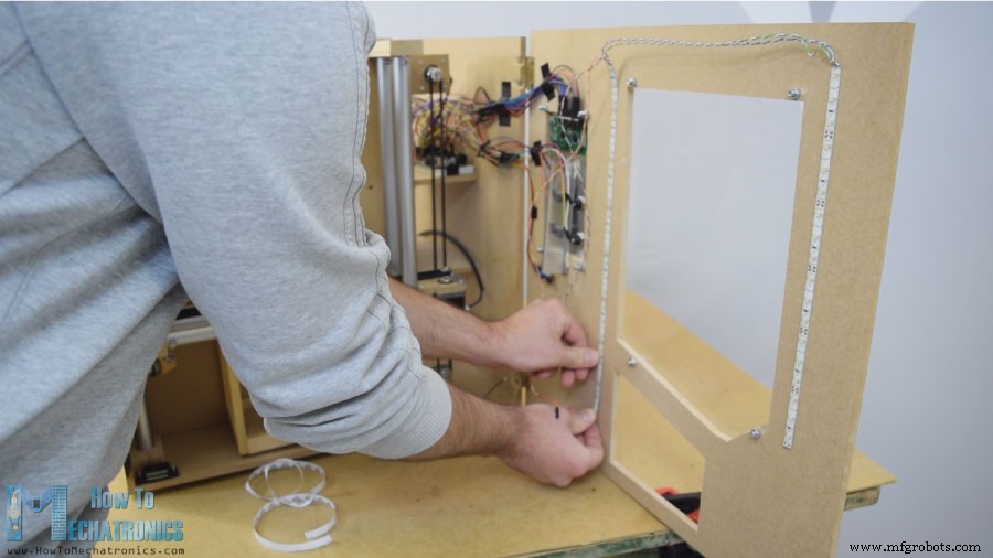
다음은 간단한 경첩을 사용하여 자판기에 부착한 전면 도어 패널이며, 이를 잠그는 데는 마그네틱 도어 캐처를 사용했습니다. 그런 다음 5mm 눈금 아크릴을 사용하여 큰 전면 개구부를 덮고 오른쪽의 작은 개구부에는 매우 주석 알루미늄 판을 사용했습니다. 여기에 버튼용 구멍 4개와 동전 및 LCD 디스플레이용 구멍을 만들었습니다. 드릴과 쇠톱을 사용하여 만들었습니다. 알루미늄판에 전자부품을 부착한 후 5mm볼트를 이용하여 전면 도어패널에 부착하였습니다.
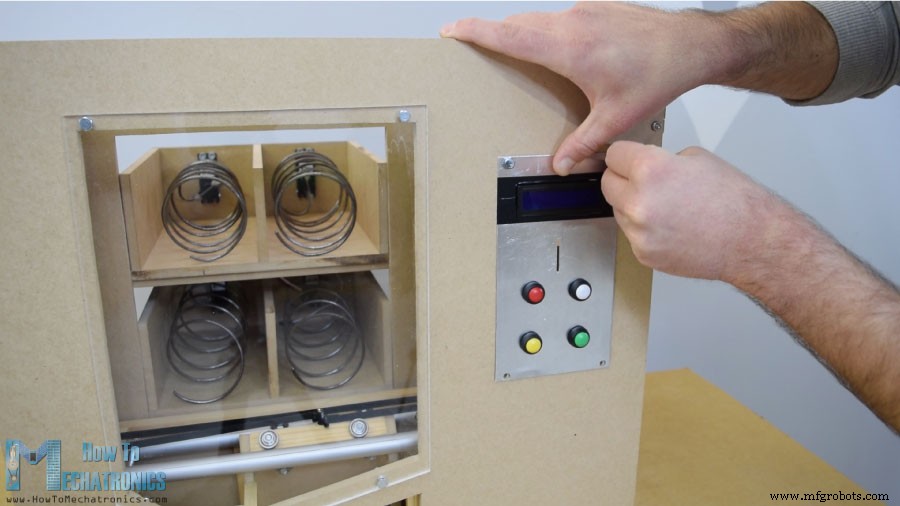
캐리어를 시작 위치에 배치하기 위해 두 개의 마이크로 스위치를 설치했고 동전을 위해 동전이 기계 바닥으로 미끄러지도록 안내하는 가이드를 붙였습니다.
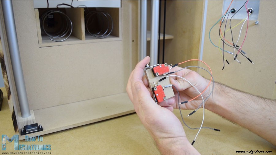
동전 감지기는 간단한 적외선 근접 센서이므로 동전이 근처를 지나갈 때 센서가 긍정적인 피드백을 제공합니다.
다음은 모든 전자 부품을 Arduino 보드에 연결하는 재미있는 부분입니다. 다음은 이 DIY 자판기 프로젝트의 전체 회로도입니다.
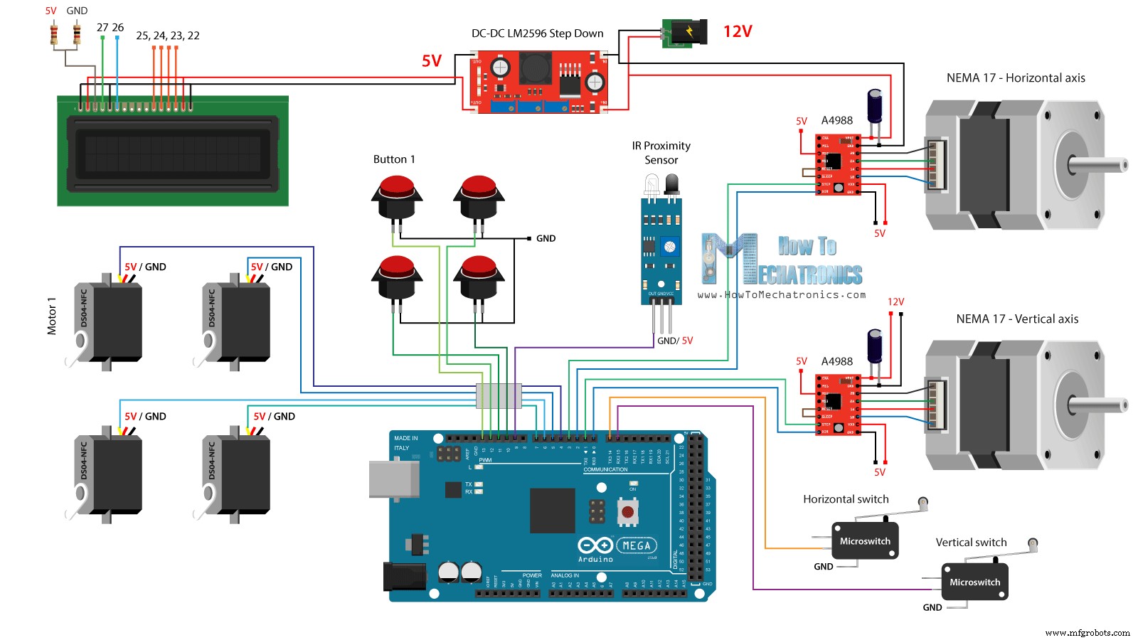
따라서 최소 2A의 12V 전원 공급 장치가 필요합니다. 2개의 스테퍼 모터를 위한 12V와 나중에 현관문에 부착할 LED 스트립 조명이 필요합니다. 그러나 다른 모든 구성 요소의 경우 5V가 필요하므로 벅 컨버터를 사용하여 12V를 5V로 낮추었습니다. DS04-NFC 연속 회전 서보 모터는 5V로 전원이 공급되고 Arduino 보드에서 오는 PWM 신호를 통해 제어되는 반면 스테퍼 모터는 A4988 드라이버를 통해 제어됩니다. 4개의 버튼과 2개의 마이크로 스위치는 접지 및 Arduino 디지털 핀에 연결되어 있으므로 Arduino 보드의 내부 풀업 저항을 사용하여 눌렀을 때 쉽게 감지할 수 있습니다.
아래 링크에서 이 Arduino 튜토리얼에 필요한 구성요소를 얻을 수 있습니다.
점프 와이어를 사용하여 전자 부품을 연결했습니다. 많은 전선으로 인해 약간 지저분해졌지만 모든 것이 제대로 작동했습니다. 마지막으로 도어 패널에 LED 조명 스트립 2개를 부착하여 자판기 내부를 비췄습니다.
이제 남은 것은 아두이노를 프로그래밍하는 일이며 이 프로젝트를 위해 만든 코드는 다음과 같습니다. 그 아래에 코드에 대한 설명이 있습니다.
/*     DIY Vending Machine - Arduino based Mechatronics Project

    by Dejan Nedelkovski, www.HowToMechatronics.com

*/

#include <LiquidCrystal.h> // includes the LiquidCrystal Library
#include <Servo.h>

LiquidCrystal lcd(27, 26, 25, 24, 23, 22); // Creates an LC object. Parameters: (rs, enable, d4, d5, d6, d7)
Servo servo1, servo2, servo3, servo4;   // DS04-NFC motors

// Stepper motors pins
#define dirPinVertical 0
#define stepPinVertical 1
#define dirPinHorizontal 2
#define stepPinHorizontal 3

#define coinDetector 9

#define button1 13
#define button2 12
#define button3 11
#define button4 10

#define microSwitchV 15
#define microSwitchH 14

int buttonPressed;

void setup() {
  lcd.begin(16, 2); // Initializes the interface to the LCD screen, and specifies the dimensions (width and height) of the display

  servo1.attach(4);
  servo2.attach(5);
  servo3.attach(6);
  servo4.attach(7);

  pinMode(dirPinVertical, OUTPUT);
  pinMode(stepPinVertical, OUTPUT);
  pinMode(dirPinHorizontal, OUTPUT);
  pinMode(stepPinHorizontal, OUTPUT);

  pinMode(coinDetector, INPUT);

  // Activating the digital pins pull up resistors
  pinMode(button1, INPUT_PULLUP);
  pinMode(button2, INPUT_PULLUP);
  pinMode(button3, INPUT_PULLUP);
  pinMode(button4, INPUT_PULLUP);

  pinMode(microSwitchV, INPUT_PULLUP);
  pinMode(microSwitchH, INPUT_PULLUP);

  // Vertical starting position
  digitalWrite(dirPinVertical, HIGH); // Set the stepper to move in a particular direction
  while (true) {
    if (digitalRead(microSwitchV) == LOW) { // If the micro switch is pressed, move the platfor a little bit up and exit the while loop
      moveUp(70);
      break;
    }
    // Move the carrier up until the micro switch is pressed
    digitalWrite(stepPinVertical, HIGH);
    delayMicroseconds(300);
    digitalWrite(stepPinVertical, LOW);
    delayMicroseconds(300);
  }
  // Horizontal starting position
  digitalWrite(dirPinHorizontal, LOW);
  while (true) {
    if (digitalRead(microSwitchH) == LOW) {
      moveLeft(350);
      break;
    }
    digitalWrite(stepPinHorizontal, HIGH);
    delayMicroseconds(300);
    digitalWrite(stepPinHorizontal, LOW);
    delayMicroseconds(300);
  }
}
void loop() {
  // Print "Insert a coin!" on the LCD
  lcd.clear();
  lcd.setCursor(0, 0);
  lcd.print("Insert a coin!");

  // Wait until a coin is detected
  while (true) {
    if (digitalRead(coinDetector) == LOW) { // If a coin is detected, exit the from the while loop
      break;
    }
  }

  delay(10);
  lcd.clear();
  lcd.setCursor(0, 0);
  lcd.print("Select your item");
  lcd.setCursor(0, 1);
  lcd.print(" 1, 2, 3 or 4?");

  // Wait until a button is pressed
  while (true) {
    if (digitalRead(button1) == LOW) {
      buttonPressed = 1;
      break;
    }
    if (digitalRead(button2) == LOW) {
      buttonPressed = 2;
      break;
    }
    if (digitalRead(button3) == LOW) {
      buttonPressed = 3;
      break;
    }
    if (digitalRead(button4) == LOW) {
      buttonPressed = 4;
      break;
    }
  }

  // Print "Delivering..."
  lcd.clear();
  lcd.setCursor(0, 0);
  lcd.print("Delivering...");

  // Depending on the pressed button, move the carrier to that position and discharge the selected item
  switch (buttonPressed) {
    case 1:
      // Move the container to location 1
      moveUp(4900); // Move up 4900 steps (Note: the stepper motor is set in Quarter set resolution)
      delay(200);
      moveLeft(1700); // Move left 1700 steps
      delay(300);
      // Rotate the helical coil, discharge the selected item
      servo1.writeMicroseconds(2000); // rotate
      delay(950);
      servo1.writeMicroseconds(1500);  // stop
      delay(500);
      // Move the container back to starting position
      moveRight(1700);
      delay(200);
      moveDown(4900);
      break;

     case 2:
      // Move the container to location 2
      moveUp(4900);
      delay(200);
      // Rotate the helix, push the selected item
      servo2.writeMicroseconds(2000); // rotate
      delay(950);
      servo2.writeMicroseconds(1500);  // stop
      delay(500);
      moveDown(4900);
      break;

      case 3:
      // Move the container to location 3
      moveUp(2200);
      delay(200);
      moveLeft(1700);
      delay(300);
      // Rotate the helix, push the selected item
      servo3.writeMicroseconds(2000); // rotate
      delay(950);
      servo3.writeMicroseconds(1500);  // stop
      delay(500);
      // Move the container back to starting position
      moveRight(1700);
      delay(200);
      moveDown(2200);
      break;

      case 4:
      // Move the container to location 4
      moveUp(2200); // Move verticaly 4800 steps
      delay(200);
      // Rotate the helix, push the selected item
      servo4.writeMicroseconds(2000); // rotate
      delay(950);
      servo4.writeMicroseconds(1500);  // stop
      delay(500);
      moveDown(2200);
      break;
  }

  lcd.clear(); // Clears the display
  lcd.setCursor(0, 0);
  lcd.print("Item delivered!"); // Prints on the LCD
  delay(2000);
}

// == Custom functions ==

void moveUp (int steps) {
  digitalWrite(dirPinVertical, LOW);
  for (int x = 0; x < steps; x++) {
    digitalWrite(stepPinVertical, HIGH);
    delayMicroseconds(300);
    digitalWrite(stepPinVertical, LOW);
    delayMicroseconds(300);
  }
}
void moveDown (int steps) {
  digitalWrite(dirPinVertical, HIGH);
  for (int x = 0; x < steps; x++) {
    digitalWrite(stepPinVertical, HIGH);
    delayMicroseconds(300);
    digitalWrite(stepPinVertical, LOW);
    delayMicroseconds(300);
  }
}
void moveLeft (int steps) {
  digitalWrite(dirPinHorizontal, HIGH);
  for (int x = 0; x < steps; x++) {
    digitalWrite(stepPinHorizontal, HIGH);
    delayMicroseconds(300);
    digitalWrite(stepPinHorizontal, LOW);
    delayMicroseconds(300);
  }
}
void moveRight (int steps) {
  digitalWrite(dirPinHorizontal, LOW);
  for (int x = 0; x < steps; x++) {
    digitalWrite(stepPinHorizontal, HIGH);
    delayMicroseconds(300);
    digitalWrite(stepPinHorizontal, LOW);
    delayMicroseconds(300);
  }
}Code language: Arduino (arduino)먼저 Servo 및 LiquidCrystal 라이브러리를 포함하고 LCD 핀, 4개의 서보 모터, 스테퍼 모터 핀, 동전 감지기, 4개의 버튼 및 2개의 마이크로 스위치를 정의해야 합니다.
설정 섹션에서 위에서 언급한 각 핀에 대한 핀 모드를 설정합니다. 버튼과 마이크로 스위치 핀에 대해 내부 풀업 저항을 활성화했음을 알 수 있습니다. 즉, 이 핀의 논리 레벨은 항상 HIGH이며, 일단 누르면 논리 레벨이 LOW로 떨어집니다.
메인 루프에 들어가기 전에 캐리어를 두 개의 마이크로 스위치로 정의된 시작 위치로 설정합니다. 따라서 while 루프를 사용하여 캐리어를 시작 위치로 계속 이동하고 두 개의 마이크로 스위치를 누르면 모터가 멈추고 원하는 시작 위치로 이동합니다.
// Vertical starting position
  digitalWrite(dirPinVertical, HIGH); // Set the stepper to move in a particular direction
  while (true) {
    if (digitalRead(microSwitchV) == LOW) { // If the micro switch is pressed, move the platfor a little bit up and exit the while loop
      moveUp(70);
      break;
    }
    // Move the carrier up until the micro switch is pressed
    digitalWrite(stepPinVertical, HIGH);
    delayMicroseconds(300);
    digitalWrite(stepPinVertical, LOW);
    delayMicroseconds(300);
  }
  // Horizontal starting position
  digitalWrite(dirPinHorizontal, LOW);
  while (true) {
    if (digitalRead(microSwitchH) == LOW) {
      moveLeft(350);
      break;
    }
    digitalWrite(stepPinHorizontal, HIGH);
    delayMicroseconds(300);
    digitalWrite(stepPinHorizontal, LOW);
    delayMicroseconds(300);
  }Code language: Arduino (arduino)
메인 프로그램에서 LCD에 "Insert a coin" 메시지를 인쇄하여 시작합니다. 그런 다음 우리는 while 루프에 갇히게 됩니다. 동전을 삽입하고 근접 센서 근처를 지나가면 동전 감지기 핀의 논리 상태가 LOW로 떨어지고 이 경우 break 문을 사용하여 while 루프에서 빠져 나옵니다.
// Wait until a coin is detected
  while (true) {
    if (digitalRead(coinDetector) == LOW) { // If a coin is detected, exit the from the while loop
      break;
    }
  }Code language: Arduino (arduino)
그런 다음 "Select your item" 메시지를 출력하고 또 다른 while 루프에 갇힙니다.
// Wait until a button is pressed
  while (true) {
    if (digitalRead(button1) == LOW) {
      buttonPressed = 1;
      break;
    }
    if (digitalRead(button2) == LOW) {
      buttonPressed = 2;
      break;
    }
    if (digitalRead(button3) == LOW) {
      buttonPressed = 3;
      break;
    }
    if (digitalRead(button4) == LOW) {
      buttonPressed = 4;
      break;
    }
  }Code language: Arduino (arduino)
이 while 루프는 네 개의 버튼 중 하나를 누르기를 기다리고 있으며 일단 누르면 빠져나와 "Delivering" 메시지를 인쇄합니다.
이제 눌려진 버튼에 따라 switch 문의 케이스 중 한 번을 실행합니다. 첫 번째 버튼을 눌렀을 경우 캐리어는 맞춤형 "moveUp()" 기능을 사용하여 이동을 시작합니다.
switch (buttonPressed) {
    case 1:
      // Move the container to location 1
      moveUp(4900); // Move up 4900 steps (Note: the stepper motor is set in Quarter set resolution)
      delay(200);
      moveLeft(1700); // Move left 1700 steps
      delay(300);
      // Rotate the helical coil, discharge the selected item
      servo1.writeMicroseconds(2000); // rotate
      delay(950);
      servo1.writeMicroseconds(1500);  // stop
      delay(500);
      // Move the container back to starting position
      moveRight(1700);
      delay(200);
      moveDown(4900);
      break;
}Code language: Arduino (arduino)
이 함수를 살펴보면 단순히 스테퍼 모터를 특정 방향으로 이동하도록 설정하고 입력한 스텝 수만큼 인수로 만드는 것을 알 수 있습니다.
void moveUp (int steps) {
  digitalWrite(dirPinVertical, LOW);
  for (int x = 0; x < steps; x++) {
    digitalWrite(stepPinVertical, HIGH);
    delayMicroseconds(300);
    digitalWrite(stepPinVertical, LOW);
    delayMicroseconds(300);
  }
}Code language: Arduino (arduino)
여기서 우리는 A4988 스테퍼 드라이버가 1/4 단계 해상도로 작동하도록 설정했음을 알 수 있습니다. 몇 가지 시식을 통해 캐리어가 상위 위치에 도달하려면 4900단계가 필요하다는 결론을 내렸습니다. 비슷한 방법으로 위치 번호 1에 도달할 때까지 캐리어를 왼쪽으로 이동합니다.
그 직후 나선형 코일이 전체 사이클을 만들도록 연속 회전 모터를 950밀리초 동안 회전합니다.
// Rotate the helical coil, discharge the selected item
      servo1.writeMicroseconds(2000); // rotate
      delay(950);
      servo1.writeMicroseconds(1500);  // stopCode language: Arduino (arduino)
이 값은 때때로 다를 수 있으며 모터 자체에 따라 다릅니다. moveRight() 및 moveDown() 사용자 정의 함수를 사용하여 캐리어를 시작 위치로 다시 가져옵니다. 같은 방법으로 4가지 항목을 모두 배출할 수 있습니다.
마지막에 "항목이 배달됨"이라는 메시지를 인쇄합니다.
매우 간단합니다. 이 비디오를 보시고 새로운 것을 배우셨기를 바랍니다. 아래 댓글 섹션에서 언제든지 질문하고 내 Arduino 프로젝트 컬렉션을 확인하세요.
제조공정
이것은 제 메카트로닉스 마지막 해 프로젝트였습니다. 스코페에 있는 기계공학부에서. 실제 팔 움직임과 3D 컴퓨터 모델의 상호작용을 가능하게 하는 기기를 개발하는 것이 목표였습니다. 나는 하나의 장치에 세 가지 다른 분야를 통합했습니다. 기계, 전기 및 컴퓨터 공학: Solidworks는 팔의 움직임을 나타내는 3D 모델을 디자인합니다. 현실 세계와 컴퓨터를 연결하기 위한 Arduino Mega 2560 카드입니다. 3D 모델 제어를 프로그래밍하기 위한 MATLAB / Simulink 다음 비디오에서 프로젝트의 프레젠테이션을
이 기계는 스코페의 기계공학부에서 학생 5명으로 구성된 팀이 건설 및 CAD 과목의 학생 프로젝트로 만든 것입니다.두 종류의 판을 분류하는 기계입니다. 한 판에는 구멍이 있고 다른 판에는 구멍이 없습니다. 우리의 임무는 이 접시를 자동으로 분류하는 기계를 개발하는 것이었습니다. 우리는 이 솔루션을 내놓았고 실제로 25개의 다른 기계 중 1위를 차지했습니다. 작동 방식 자동 분류기는 다음과 같이 작동합니다. 판은 손으로 기계에 공급됩니다. 롤러가 플레이트를 정렬하여 플레이트 매거진에 하나씩 떨어집니다. 판이 분류기 바닥에 도달