

제조공정

산업 제조
고로 공정에 의한 제철의 화학
낮은 코크스 비율로 작동하는 현대식 고로(BF)는 주로 향류 기체-고체 반응기의 고유한 특성 때문에 효율적인 처리 장치입니다. 이 개념을 성공적으로 사용하려면 로에 장입된 각 재료가 균일한 물리적 특성과 균일한 구성을 가져야 합니다. 또한 각 재료는 용해가 발생하는 용광로를 통해 아래로 이동할 때 이 좋은 물리적 특성을 유지해야 합니다.
산화철, 코크스 및 슬래그 형성 물질이 용광로 스택을 통해 아래로 이동함에 따라 몇 가지 중요한 교환 공정이 발생합니다. 주로 일산화탄소(CO), 이산화탄소(CO2) 및 질소(N2)로 구성된 상승로 가스에서 열이 제거되어 하강하는 부하 재료로 전달됩니다. 산소(O2)는 하강하는 산화철에서 제거되어 상승하는 환원 가스로 전달됩니다. 따라서 이 매우 효율적인 역류 반응기 내에서 화학 반응이 일어나고 충전물이 하강함에 따라 부하 물질의 온도가 증가하고 환원된 철, 산화철 및 슬래그 형성 물질의 융합이 시작되고 최종적으로 액체 금속 및 슬래그가 내부에 수집됩니다. 용광로의 난로. 용광로에 장입된 코크스의 대부분은 열과 환원제 CO를 제공하기 위해 송풍구의 뜨거운 공기 분사에서 산소와 함께 연소됩니다.
BF 상단으로 장입된 부하 물질과 코크스가 굴뚝을 통해 하강할 때 송풍구에서 상승하는 뜨거운 가스에 의해 예열됩니다. 이 예열의 결과 코크스는 송풍구에 인접한 노의 하부에 도달하여 열풍 공기와 접촉할 때 큰 강도로 연소합니다. 그러나 매우 높은 온도(약 1,650℃)와 코크스로 존재하는 많은 양의 탄소(C)로 인해 형성된 CO2는 안정적이지 않고 추가 탄소와 즉시 반응하여 CO를 형성합니다. 그 결과, BF의 탄소(코크스)는 화학식 2C + O2 =2CO로 표현할 수 있습니다. 델타 H =+110,458 kJ/kmol. 현대식 BF의 작동에서 250kg(kg)에서 400kg의 탄소가 생산된 1톤의 뜨거운 금속에 대해 이러한 방식으로 반응합니다. 이 반응은 제련 작업을 위한 주요 열원이며 또한 환원 가스(CO)를 생성합니다. 환원 가스(CO)는 가열로 스택으로 상승하여 가열로로 내려가면서 부하에 있는 산화철의 대부분을 예열하고 감소시킵니다.
분사 공기의 모든 수분(H2O)도 연소 구역의 코크스에 있는 일부 탄소와 반응합니다. 이 반응은 연소처럼 열을 생성하지 않고 오히려 열을 소비합니다. 그러나 모든 탄소 단위에 대해 이 반응은 탄소가 공기 중에서 연소될 때 생성되는 것보다 더 많은 환원 가스를 생성합니다. 탄소는 공기 중에서 연소할 때 1단위의 CO만 생성하지만 H2O와 반응하면 1단위의 CO와 1단위의 수소(H2)를 생성합니다. 따라서 어떤 경우에는 부하 재료의 고유한 감소율이 정상보다 낮고 상대적으로 높은 열풍 온도(1,000℃에서 1,200℃ 사이)를 이용할 수 있는 곳에서 유지하는 것이 유리하다고 생각되었습니다. BF 가스의 환원력을 증가시키기 위해 수분(증기) 첨가에 의해 균일하게 높은 수준으로 폭발의 수분 함량. 보조 연료 분사는 유사한 이점을 제공합니다. 이 화학 반응은 C + H2O =CO + H2 방정식으로 표현됩니다. 델타 H =+131,378 kJ/kmol. 추가 이점은 용광로 환원 가스에 수소를 도입(또는 증가)시키는 것입니다. 수소 비율이 증가함에 따라 기체의 밀도는 감소합니다. 그 결과 동일한 양의 환원 가스가 생성되어 부담에 대한 저항이 적습니다.
상승하는 가스는 온도가 925℃ 미만인 BF 상부에 있는 부담의 산화철을 감소시키기 시작합니다. 이 온도에서 화학 평형은 모든 CO 및 H2가 환원에 사용되는 것을 방지합니다(평형 CO / CO2 비율은 Wustite의 환원에 대해 약 2.3이며 비율이 이 값 이하로 떨어지면 철은 재산화되므로 철 산화물에 대한 CO 또는 H2의 분자 비는 화학량론적 반응(i ) 1/2 Fe2O3 + 3/2 CO =Fe + 3/2 CO2, 델타 H =+12,866 kJ/kmol, (ii) 1/3 Fe3O4 + 4/3 CO =Fe + 4/3 CO2, 델타 H =+3940 kJ/kmol, (iii) FeO + CO =Fe + CO2, 델타 H =–16,108 kJ/kmol, (iv) 1/2 Fe2O3 + 3/2 H2 =Fe + 3/2 H2O, 델타 H =+ 48,953kJ/kmol, (v) 1/3 Fe3O4 + 4/3 H2 =Fe + 4/3 H2O, 델타 H =+51,042kJ/kmol, (vi) FeO + H2 =Fe + H2O, 델타 H =+ 25,104kJ/kmol.
과거에는 이러한 유형의 환원을 직접 환원이라고 하는 고온에서 발생하는 유형과 대조적으로 간접 환원이라고 했습니다. 그러나 이러한 명명법은 Wiberg, HIB, FIOR 및 유사한 공정과 같은 DRI 공정을 설명할 때 이러한 동일한 화학 반응을 직접 환원이라고 부르기 때문에 혼동을 일으키게 되었습니다. 이러한 이유로 이러한 용어는 과거와 같이 일반적으로 사용되지 않습니다.
온도가 비교적 낮은 로 상부에서 환원되지 않는 산화철의 부분은 온도가 매우 높은 하부에서 환원되어야 한다. CO2와 H2O는 다량의 코크스가 존재하는 이러한 온도에서 안정하지 않기 때문에 생성되는 것과 거의 같은 속도로 탄소와 반응합니다. 결과적으로, 노의 이 부분에서 전체 환원 반응은 반응 FeO + C =Fe + CO로 나타낼 수 있습니다. delta H =+156,482 kJ/kmol은 H2나 CO가 반응물인지에 관계없이 이 반응은 FeO + CO =Fe + CO2 반응 중 하나를 대수적으로 추가하여 얻습니다. 델타 H =–16,108 kJ/kmol, CO2 + C =2CO; 델타 H =+172,590 kJ/kmol 또는 반응 FeO + H2 =Fe + H2O; 델타 H =+25,104 kJ/kmol 및 H2O + C =CO + H2; 델타 H =+131,378 kJ/kmol.
환원 반응 FeO + C =Fe + CO는 많은 양의 열을 흡수하므로 이러한 방식으로 발생하는 환원량이 많을수록 더 많은 열량이 로에 공급된다. 이 반응은 또한 BF 스택에서 발생하는 환원 반응에 사용되는 가스인 CO를 생성합니다. 대부분의 경우 FeO + C =Fe + CO 반응에 따라 환원의 약 1/3이 수행되고 Fe2O3 + 3 CO =2 Fe + 3 CO2 반응에 따라 나머지가 수행될 때 가장 효율적인 작동이 달성됩니다. FeO + H2 =Fe + H2O.
대부분의 BF에서 대략 40%가 열풍 공기의 현열에서 공급되기 때문에 공정의 열은 코크스의 연소에 의해 완전히 생성되지 않습니다. 연료의 상당 부분은 천연 가스, 타르, 연료유 또는 석탄으로 분쇄되거나 입상 형태로 풍구를 통해 경제적으로 주입될 수 있습니다. 이러한 경우 연료의 탄소는 CO로 연소되지만 다량의 코크스가 존재하기 때문에 수소는 H2로 남아 있고 송풍구 위 어딘가에서 산화철을 환원할 때까지 산화되지 않습니다.
용광로 장입물의 철 함유 성분은 철, Fe2O3 및 Fe3O4의 단순 산화물입니다. 천연 광석은 일반적으로 적철광(Fe2O3) 또는 자철광(Fe3O4)입니다. 펠렛은 주로 Fe2O3입니다. 철광석 소결체는 Fe2O3 및 Fe3O4에서 자철석, fayalite, 2FeO.SiO2 및 di-calcium ferrite를 포함하는 용융 혼합물에 이르기까지 조성 범위가 다양할 수 있습니다. 산화철의 환원은 일반적으로 단계적으로 발생합니다. CO와의 반응은 방정식 (i) 3Fe2O3(s) + CO(g) =2Fe3O4(s) + CO2(g)로 제공됩니다. 델타 H -48 kJ, (ii) Fe3O4(s) + CO(g) =3FeO(s) + CO2(g); 델타 H -21.7 kJ 및 (iii) FeO(s) + CO(g) =Fe(s) + CO2(g); 델타 H -11 kJ. 이러한 반응은 연속적으로 더 높은 온도에서, 그리고 용광로에서 더 멀리 떨어져서 수행됩니다.
상승하는 가스에 의한 이러한 반응을 완료하려면 계속해서 더 높은 비율의 CO가 필요합니다. 가스의 전체 CO가 각 반응에 대해 CO2로 전환되는 것은 불가능하다는 것을 인식해야 합니다. 예를 들어, 3개의 방정식에 대해 상수 K3에 의해 주어지는 평형 비율이 있고 K3 =P CO2 / P CO는 온도 의존적입니다. 800℃에서 평형 기체 혼합물은 약 65% CO와 35% CO2를 포함합니다. 이 온도에서 FeO 및 고체 철과 접촉하는 가스에서 CO2 함량이 이 값을 초과하면 존재하는 철이 FeO로 다시 산화되는 경향이 있습니다. 따라서 이러한 반응이 일어나도록 하기 위해서는 그림 1과 같이 각 단계에서 상당한 양의 CO 농도가 필요하며, 반응에 의해 CO를 CO2로 완전히 전환시키는 것은 불가능하다. 그림 1은 Fe-C-O 및 Fe-H-O 시스템의 안정성 다이어그램을 보여줍니다. Fe-C-O 시스템의 S 곡선은 '용액 손실' 또는 Boudouard 또는 반응을 나타냅니다.
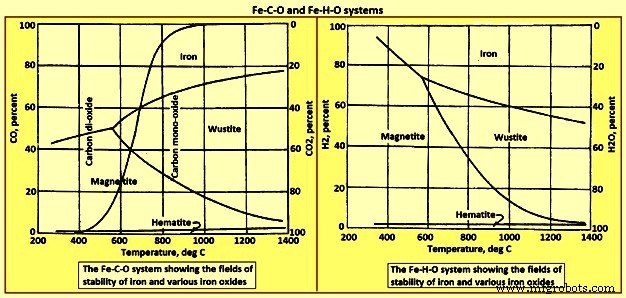
그림 1 Fe-C-O 및 Fe-H-O 시스템
보조 연료의 수소와 연료의 수분 및 공기 분사로 인해 송풍구에서 나오는 가스도 최대 2% 또는 3%의 수소를 함유할 수 있습니다. 용광로 제어를 돕기 위해 뜨거운 공기 분사에 증기를 추가할 수 있습니다. 코크스와 연료의 탄소에 의한 증기의 환원은 전체 반응 H2O(g) + C(s) =CO(g) + H2(g)에 의해 진행됩니다. 델타 H =131.3 kJ. 이 반응은 흡열 반응인 반면 폭발에서 산소에 의한 탄소의 산화는 식 C(s) + 1/2 O(g) =CO(g)에 의해 CO를 형성합니다. 델타 H =-110.5 kJ는 발열입니다. 수소에 의한 산화철의 환원은 또한 단계 (i) 3Fe2O3(s) + H2(g) =2Fe3O4(s) + H2O(g); 델타 H =-7.1kJ, (ii) Fe3O4(s) + H2(g) =3FeO(s) + H2O(g); 델타 H 62.9 kJ, (iii) FeO(s) + H2(g) =Fe(s) + H2O(g); 델타 H =30.2kJ. 온도는 이러한 반응의 평형에 영향을 미칩니다.
수성 가스 전환 반응 CO2(g) + H2(g) =H2O(g) + CO(g); 델타 H =41.2 kJ는 산소를 재분배하고 수소 함유 가스 종과 탄소 함유 가스 종을 평형 상태로 만들기 위해 기상의 다양한 종 사이에서 발생할 수 있습니다. 이 반응은 열이 거의 필요하지 않으며 평형 상수(PH2O.P CO)/(PH2.P CO2)는 825℃에서 1입니다. 스택의 가스는 산화물뿐만 아니라 코크스의 탄소와도 반응합니다. 책임에서 철의. CO 및 CO2와 흑연으로서의 탄소의 전체 반응은 '용액 손실' 또는 Boudouard 반응 CO2(g) + C(s) =2CO(g)입니다. 델타 H 172.4 kJ. 반응의 평형은 750 deg C 이상의 온도에서 오른쪽으로 강하게 이동합니다. 600 deg C 미만에서는 평형이 강하게 왼쪽으로 이동하여 탄소가 노 부하 2CO(g) =C(s ) + CO2(g); 델타 H =-172.4. 그림 1의 왼쪽 하단에서 상단 중앙으로 이어지는 'S'자 곡선은 평형을 나타냅니다. 온도와 조성이 선 위에 위치하는 기체는 두 번째 반응에 의해 탄소를 침착시키는 경향이 있고, 조성과 온도가 선 아래에 있는 기체는 첫 번째 반응에 따라 탄소를 산화시킵니다.
고온에서 탄소 용액 반응의 주요 효과는 필요한 풍구에서 발생하는 열의 상대적 감소와 700℃ 이상의 노 영역에서 가스의 CO 농도 증가입니다. 이 후자의 조건은 다음과 같습니다. 가스의 부피를 증가시키고 열 전달을 돕기 때문에 특히 바람직합니다. 용액 손실 반응과 FeO(s) + CO(g) =Fe(s) + CO2(g) 반응의 조합; 델타 H -11 kJ는 FeO(s) + C(s) =Fe(s) + CO(g) 방정식으로 주어진 탄소에 의한 FeO의 '직접' 환원에 해당합니다. 델타 H =131.3 kJ. 스택을 통과하는 가스는 일반적으로 코크스의 탄소 및 하강 부하의 산화철과 평형을 이룰 수 없다는 것이 그림 1에서 분명합니다. BF 스택의 가스 구성과 온도 사이의 실제 관계는 실제로 사용되는 방식에 따라 크게 달라집니다.
산화물의 상대적 안정성
다양한 산화물의 상대적인 안정성은 온도에 대한 Ellingham 다이어그램(그림 2)에 표시됩니다. Ellingham 다이어그램은 BF에서 산화물의 거동을 이해하는 데 매우 유용합니다. 상대적 안정성은 산화물 형성의 자유 에너지 측면에서 측정됩니다. 산화물 형성의 음의 자유 에너지가 높을수록 산화물 안정성이 높아집니다. 즉, 다이어그램 상단에 위치한 산화물은 안정성이 상대적으로 낮고, 하단에 위치한 산화물은 안정성이 높다는 의미입니다. 다이어그램의 중앙에 위치한 산화물은 중간 정도의 안정성을 가지고 있습니다. 비교적 안정성이 낮은 산화물에는 산화칼륨, 산화나트륨, 산화인 및 산화철이 포함됩니다. 적당한 안정성을 가진 산화물에는 망간 산화물, 크롬 산화물, 실리카 및 티타늄 산화물이 포함됩니다. . 안정성이 높은 산화물에는 알루미나, 마그네시아 및 석회가 포함됩니다.
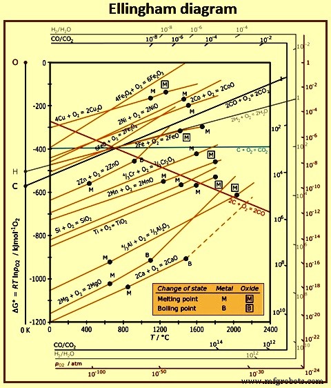
그림 2 Ellingham 다이어그램
산소에 대한 원소의 친화성 측면에서 이 도표를 고려하는 것도 유용합니다. 예를 들어, 다이어그램 상단에 위치한 요소는 산소 친화도가 낮고, 다이어그램 하단에 위치한 요소는 산소 친화도가 높습니다. 이것은 상부의 산화물은 상대적으로 환원하기 쉬운 반면 하부의 산화물은 환원하기 어렵다는 것을 의미합니다. 이것은 BF 노상에서 발견되는 온도에 해당하는 온도에서 산화철 형성 라인 위에 있는 산화인 형성 라인에 의해 나타납니다. 이것은 인 산화물이 산화철보다 안정성이 낮고, 따라서 노의 환원 조건이 산화철을 환원시키기에 충분하기 때문에, 로에 들어가는 본질적으로 모든 인은 결국 뜨거운 금속으로 된다는 것을 의미합니다. 반면에 알루미나, 마그네시아, 석회와 같은 안정한 산화물은 BF 조건에서 환원되지 않고 결국 슬래그 상태가 된다. 망간 산화물, 크롬 산화물, 실리카 및 티타늄 산화물과 같은 적당한 안정성을 갖는 산화물은 부분적으로 환원되어 일부 망간, 크롬, 실리콘 및 티타늄이 뜨거운 금속에 용해되고 나머지 환원되지 않은 산화물은 슬래그의 일부를 구성합니다.
Ellingham 다이어그램은 단위 활동도의 순수한 원소가 1몰의 산소 기체와 반응하여 단위 활동도의 순수한 산화물을 형성하는 것을 기반으로 구성됩니다. 열역학적 용어 '활성'은 액체 철에 용해된 원소 또는 액체 슬래그에 용해된 산화물의 거동을 논의하는 데 특히 유용한 개념입니다. 예를 들어, 산소나 황과 같은 소량의 원소가 용강에 용해되어 있을 때 이들의 활성은 농도(%)와 같은 것으로 간주할 수 있습니다. 그러나 고농도의 다른 원소, 예를 들어 뜨거운 금속의 탄소가 있는 경우 황의 활성은 농도보다 높고 산소의 활성은 농도보다 낮습니다. 이러한 경우 활동과 집중을 구별하는 것이 중요합니다. · 용액 내 성분의 농도는 해당 성분이 얼마나 존재하는지를 나타내는 척도입니다. · 솔루션에서 구성 요소의 활동은 구성 요소가 실제로 어떻게 작동하는지 측정합니다.
탄소를 포함하는 선을 제외한 Ellingham 다이어그램의 모든 선은 양의 기울기를 가지며, 이는 온도가 증가함에 따라 산화물 안정성이 감소함을 나타냅니다. 산화칼륨, 산화나트륨, 마그네시아, 석회의 산화물에 대한 선은 각각 금속의 끓는점에 해당하는 온도에서 기울기가 증가하는 것을 보여줍니다. 탄소와 산소로부터 CO2가 형성되는 선은 기울기가 거의 0에 가까워 온도가 증가함에 따라 안정성의 변화가 거의 없음을 나타내는 반면, CO에 대한 기울기는 강한 음의 기울기를 가지므로 온도가 증가함에 따라 실제로 CO의 안정성이 증가함을 의미합니다. 두 탄소 산화물에 대한 선은 약 700℃에서 교차합니다. 이 온도 이상에서는 CO가 CO2보다 더 안정적이고 낮은 온도에서는 CO2가 CO보다 더 안정적입니다.
탄소-산소 반응
약 1,000℃~1,200℃의 온도와 0.2~0.3MPa의 압력에서 풍구를 통해 주입되는 예열된 공기 분사는 각 풍구 앞에 배 모양의 반응 구역을 생성합니다. 이 지역의 온도는 약 2,000℃이며 과잉 산소와 코크스 사이에 빠른 반응이 먼저 일어나 CO2를 생성합니다. 이것은 발열 반응(C + O2 =CO2)입니다. 이 구역의 바로 외부에는 더 이상 사용 가능한 유리 산소가 없으며 CO2는 과량의 코크스와 반응하여 CO(CO2 + C =2CO)를 생성합니다. 이것은 Boudouard 반응으로 알려져 있으며 흡열입니다. 이 두 반응을 결합하면 탄소와 산소가 부분 연소되어 CO가 생성됩니다(2C + O2 =2CO). CO2 1몰을 형성할 때 발생하는 열은 CO 1몰 형성에 대한 열의 약 3.5배이며 BF 효율의 한 척도는 코크스의 탄소가 CO2로 전환되는 정도입니다.
700℃ 이하에서는 CO2가 CO보다 더 안정적이고 두 번째 반응은 왼쪽으로 진행됩니다(2CO =C + CO2). 이 반응을 흔히 탄소 증착이라고 합니다. 700 ℃ 이상에서는 CO가 CO2보다 더 안정하고 두 번째 반응은 오른쪽으로 진행됩니다. 이 반응은 때때로 탄소 용액 손실 반응이라고 하며 이러한 의미에서 부정적인 행동을 의미합니다. 다른 한편으로, 반응은 700℃ 이상의 노 영역 내에서 환원성 가스의 재생을 나타낸다. 이것은 BF 내 코크스의 중요한 기능 중 하나이며 가스의 부피를 증가시키고 열에 도움이 되기 때문에 특히 바람직하다. 옮기다. 그러나 이 반응은 흡열 반응으로 송풍구 내에서 발생하면 고온이 중요한 위치에서 냉각 효과가 발생합니다.
0.1 MPa 및 0.3 MPa 압력에서 코크스와 CO와 CO2를 포함하는 가스 혼합물 사이의 평형 반응에 대한 온도의 영향은 그림 3에 나와 있습니다. 그래프의 왼쪽에 있는 더 낮은 온도에서 CO2는 CO2보다 더 안정적입니다. 이 그림에서 1,000℃ 이상에서 코크스와 평형 상태에 있는 CO2의 비율은 본질적으로 0이라는 것이 분명합니다. 한편, 400℃ 이하의 온도에서는 CO 농도가 낮다. 따라서 1,000 deg C에서 400 deg C 사이의 온도가 감소함에 따라 CO의 안정성은 감소하는 반면 CO2의 안정성은 증가하고 코크스와 평형을 이루는 두 가스의 분압은 상당합니다.
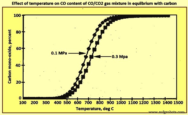
그림 3 탄소와 평형을 이루는 CO/CO2 가스 혼합물의 CO 함량에 대한 온도의 영향
노의 상부를 떠나는 가스는 일반적으로 약 200℃이고 코크스와 평형이 달성되면 CO 대 CO2의 비율은 약 10 대 -5가 됩니다. 사실, 비율은 일반적으로 1과 3 사이입니다. 즉, 가스는 평형 고려 사항에서 예측된 것보다 훨씬 더 환원되고 가스의 환원 가능성이 충분히 사용되지 않습니다. 이것은 코크스 비율이 이론상의 요구 사항을 초과한다는 것을 의미합니다. 가스와 코크스 사이의 이러한 평형 부족은 주로 굴뚝에서 높은 가스 속도에 기인할 수 있습니다. 용광로의 가스 보유 시간은 약 10초에 불과하며 특히 느슨하게 채워진 코크스가 풍부한 지역에서 매우 높은 속도가 발생할 수 있습니다. 또 다른 요인은 가스 온도가 용광로를 통과할 때 약 1,800℃까지 떨어지므로 평형이 유지될 기회가 거의 없다는 것입니다.
탄소 침착 반응
1,000℃ 미만의 온도에서 BF 스택 내 가스의 CO 함량은 요구되는 것보다 상당히 높기 때문에 탄소 침착 또는 그을음 반응이 진행되는 구동력이 존재합니다. 이 추진력은 500 deg C와 700 deg C 사이에서 특히 강합니다. 그림 3의 선보다 높은 온도와 조성을 가진 기체는 2CO =C + CO2 반응에 의해 탄소를 침착시키는 경향이 있고, 그 이하의 조성과 온도를 가진 기체는 라인은 CO2 + C =2CO 반응에 따라 탄소를 산화시킵니다. 다행스럽게도 탄소 증착 반응이 느리고 평형에 도달하지 못합니다. 그렇지 않으면 스택 상단의 부하 내부 공간이 심각하게 막힐 수 있습니다.
이것은 차례로 환원 가스의 불규칙한 흐름과 부담의 고르지 못한 하강으로 이어질 수 있습니다. 부분 반응의 경우에도 탄소가 핵 생성 및 성장할 수 있는 적절한 촉매 표면이 필요합니다. 철 입자, 부분 환원 철광석, 철 탄화물이 모두 가능한 촉매로 제안되었습니다. 반응은 수소와 수증기에 의해 강화되는 반면 암모니아, 황화수소 및 이황화탄소와 같은 질소 및 황 화합물은 억제제로 작용합니다. 산화아연과 알칼리성 화합물은 황의 억제 효과에 반대하며, 노에서 이러한 화합물의 농도는 일반적으로 낮지만 난로의 고온에서 휘발하고 굴뚝의 더 차가운 영역에서 다시 응축됩니다. 누적 효과는 그러한 화합물이 황의 영향을 상쇄할 수 있다는 것입니다. 반응에 의해 퇴적된 탄소는 매우 미세하게 분할된 형태이며 일부는 철광석 입자의 기공 내에 수용될 수 있고 스택 아래로 다시 처리될 수 있습니다. 이것은 여러 가지 방법으로 감소 프로세스에 영향을 줄 수 있습니다.
탄소의 활성 특성과 광석과의 밀접한 연관 때문에 고체 탄소에 의한 환원은 코크스에 의한 환원에 필요한 온도보다 낮은 온도에서 일어날 수 있습니다. 고체 입자 사이의 접촉. 이러한 환원 속도는 입자 내부에서 접촉 지점까지의 산소 확산 속도에 따라 달라집니다. 로 상부에서 코크스에 의한 환원은 기체 환원에 비해 무시할 수 있다. 그것은 가스 반응이 슬래그 형성에 의해 방해를 받는 약 1,000 ℃ 이상에서만 상당해집니다. 대조적으로, 침전된 탄소에 의한 환원은 800℃의 낮은 온도에서 발생할 수 있습니다.
기공 내에서 반응하는 동안 CO의 형성은 입자 내에 깊은 균열을 열어 기체-고체 접촉 면적을 증가시키고 기체 환원 효율을 증가시키는 경향이 있습니다. 기체 환원 반응에 의해 입자의 기공 내에서 CO2가 생성되면 기공 내의 탄소와 반응하여 CO로 빠르게 재생될 수 있으므로 반응을 계속할 수 있습니다.
불행하게도, 탄소 침착 반응은 또한 특정한 역효과를 가질 수 있습니다. 반응은 활성 철 반점, 온도가 약 500°C ~ 550°C인 영역, 예를 들어 스택의 낮은 수준에 있는 외부 쉘 또는 상부에 있는 내부 쉘 내부와 같은 영역에서 증착에 의해 내화물의 분할을 유발할 수 있습니다. 수준. 과량의 경우 탄소 침착으로 인해 광석 펠릿이나 소결체가 가루로 부서져 가스 흐름이 불규칙해지고 하중이 고르지 않게 내려갈 수 있습니다.
탄소 증착 반응은 발열 반응이므로 배출 가스의 온도가 증가합니다. 탄소 침착 반응의 전반적인 효과는 논쟁의 여지가 있지만 몇 가지 사실은 남아 있습니다. 반응은 배출 가스의 CO/CO2 비율을 감소시킵니다. 반응은 일정량의 탄소를 재순환시키며, 그렇지 않으면 용광로에서 배출되므로 탄소와의 반응 시간을 늘리고 환원 공정의 화학적 효율성을 높입니다.
산화철 감소
CO에 의한 산화철의 환원은 (i) 3Fe2O3 + CO =2Fe3O4 + CO2, (ii) Fe3O4 + CO =3FeO + CO2, (iii) FeO + CO =Fe + CO2의 반응으로 나타낼 수 있습니다. 이러한 반응은 그림 1과 같이 CO의 비율이 증가하면서 점점 더 높은 온도에서 수행됩니다. 이는 상대적으로 달성하기 쉬운 반응 (i) 및 (ii)가 상부 영역 내에서 일어날 수 있음을 의미합니다. 노. 철에서 마지막 양의 산소를 제거하는 것을 수반하는 반응 (iii)은 실제로 가장 달성하기 어려우므로 온도가 더 높고 환원 가스의 CO 함량이 더 높은 노 아래에서 더 멀리 발생합니다. 570℃ 이하에서는 비화학량론적 우스타이트 상(FexO)이 불안정하며 자철광을 직접 철로 환원시키는 것이 가능합니다.
특정 온도에서 특정 산화물의 환원에 필요한 가스 혼합물의 최소 CO 함량이 있습니다. 이것은 환원 반응이 계속된다면 가스의 전체 CO가 CO2로 전환되는 것이 불가능하다는 것을 의미합니다. 예를 들어, 800℃에서 FeO 및 고체 철과 접촉하는 평형 기체 혼합물은 약 65% CO 및 35% CO2를 함유합니다. 가스의 CO2 함량이 이 온도에서 이 값을 초과하면 철은 다시 FeO로 산화되는 경향이 있습니다. 따라서 이러한 반응이 일어나기 위해서는 그림 1과 같이 각 단계에서 가스의 최소 CO 농도가 있어야 하며 이러한 반응에 의해 CO를 CO2로 완전히 전환시키는 것은 불가능합니다. 다행스럽게도 이러한 온도에서 환원 반응에 의해 생성된 CO2는 코크스의 존재하에 불안정하고 CO는 환원 반응을 계속할 수 있도록 CO2 + C =2CO 반응을 기반으로 재생됩니다. 이 반응과 반응 (iii)의 조합은 탄소에 의한 FeO의 '직접' 환원(FeO + C =Fe + CO)에 해당하며 이는 강력한 흡열 반응이라는 점에 주목할 가치가 있습니다.
산화철의 환원은 또한 두 개의 환원 가스인 CO와 수소를 생성하기 위해 송풍구를 통해 주입된 보조 연료의 부분 연소에 의해 생성된 수소에 의해 발생할 수 있습니다. 수소는 또한 용광로 제어에 도움이 되는 증기가 폭발에 추가될 때 생성됩니다. CO를 형성하기 위한 열풍 폭발에서 산소에 의한 탄소의 산화는 발열성인 반면, CO와 수소(H2O + C =CO + H2)를 형성하기 위한 코크스에 의한 수분의 환원은 강한 흡열입니다.
수소에 의한 산화철의 환원은 다시 순차적으로 진행된다. 반응은 (i) 3Fe2O3 + H2 =2Fe3O4 + H2O, (ii) FeO + H2 =Fe + H2O, (iii) Fe3O4 + H2 =3FeO + H2O입니다. 이러한 반응 평형에 대한 온도의 영향은 그림 1에 나와 있습니다. 반응(i)은 약간 발열성인 반면 반응(ii) 및 (iii)은 흡열성입니다. 수소의 존재는 작은 크기로 인해 확산성이 높기 때문에 BF 가스의 밀도와 점도를 현저히 감소시키고 특히 고온에서 저환원성 원료의 감소를 향상시킵니다. 수성 가스 전환 반응(CO2 + H2 =H2O =CO)은 수소 함유 가스와 탄소 함유 가스를 평형 상태로 만들기 위해 기상의 다른 구성 요소 사이에서 발생할 수 있습니다.
그림 1에서 노를 통과하는 가스는 코크스의 탄소와 평형을 이룰 수 없고 동시에 하강 부하의 산화철과 평형을 이룰 수 없다는 것이 분명합니다. 약 800℃ 이상에서 탄소와 가스의 반응은 산화물보다 더 빠르며 코크스와 기상 사이의 평형은 아마도 상당히 근접하게 접근할 것입니다. 작동로에서 가스의 온도 및 조성 측정은 800℃ 이상에서 CO/CO2-C 라인과 FeO/Fe 라인 사이에 떨어지는 경향이 있으며, 600℃에서 800℃ 사이에서 FeO/Fe 라인을 절단하는 경향이 있음을 나타냅니다. 그런 다음 Fe3O4/Fe 라인 또는 바로 위에 유지됩니다. 600℃ 미만의 온도에서는 매우 빠른 가스 흐름으로 인해 고체와 반응할 시간이 거의 없으며 가스의 CO 함량은 코크스와 평형을 이루는 것보다 훨씬 많습니다.
산화철이 다른 산화물과 화학적으로 결합하면 BF에서 활성이 감소합니다. 이것은 산화철이 환원하기 더 어렵고 필요한 CO/CO2 비율이 여기에서 일반적으로 고려되는 것보다 높다는 것을 의미합니다. 예를 들어 규산 제1철의 경우 700℃에서 환원에 필요한 최소 CO/CO2 비율은 약 1.5에서 약 22로, 즉 탄소질 가스 기준으로 약 60% CO에서 거의 96% CO로 증가해야 합니다. 복합 산화물은 환원하기가 더 어렵기 때문에 환원을 위해 더 높은 온도가 필요하고 따라서 슬래그 형성이 일어나기 전에 CO로 달성되는 환원량이 감소된다. 이는 용광로 하부에 필요한 환원량이 증가하기 때문에 코크스율이 증가함을 의미한다.
화로와 난로에서의 반응
기타 산화물의 환원 – MnO + CO =Mn + CO2 반응이 평형 상태에서 CO의 비율이 매우 가깝기 때문에 생성물이 순수한 금속인 경우 망간 산화물 및 실리카와 같은 산화철보다 더 안정적인 산화물의 환원은 BF에서 일어나지 않습니다. 100%로. 즉, 환원 효율이 극히 낮고, 극소량의 환원 망간을 위해서는 막대한 양의 가스가 필요하다. 실리카는 매우 안정적인 산화물이기 때문에 상황은 훨씬 더 극단적입니다. 그러나 망간과 규소를 철에 녹임으로써 MnO + CO =Mn(철에 용해) + CO2, SiO2 + 2CO =Si(철에 용해) + 2CO2 반응이 약간 오른쪽으로 이동하여 금속과 슬래그 사이의 망간과 규소 분포는 슬래그 조성과 온도의 함수입니다. 이들 두 원소의 환원은 흡열적이기 때문에, 용선 내의 각각의 양은 온도에 따라 증가하고 반응의 정도는 노의 노로의 온도를 제어함으로써 어느 정도 제어된다. 더 중요한 것은 이러한 반응에 의해 생성된 CO2가 Boudouard 반응에 의해 반응하여 코크스 소비를 증가시킨다는 사실입니다.
감소된 망간의 양은 또한 장입된 광석의 양에 따라 분명히 달라집니다. 최대 2%의 망간을 함유한 광석은 고온 금속에 일반 망간 함량보다 훨씬 더 많이 함유되어 결과적으로 생성된 고온 금속 톤당 더 높은 코크스 비율을 제공합니다. 용광로의 불규칙한 부하 또는 온도 변화로 인한 실리콘 '흔들림'은 또 다른 심각한 영향을 미칠 수 있습니다. 실리콘은 용융 금속으로 환원되어 슬래그에서 고갈되어 염기도 비율이 증가하고 융점 및 온도가 변하기 때문입니다. 슬래그의 유동성은 때때로 극적으로 증가합니다.
일산화규소(SiO) 형성의 영향 – For several years it was considered that silica and manganese oxide are reduced directly from the slag by reaction with carbon in iron according to the reactions (i) SiO2 (slag) + 2C =Si + 2CO (g), and MnO (slag) + C =Mn + CO (g). It was thought that liquid iron droplets picked up silicon as they passed through the slag phase and on into the hearth. Various studies however, have shed new light on these reactions and also those involving sulphur. Several laboratory studies together with plant data have shown that at the temperature of the combustion zone, around 2,000 deg C, SiO gas is produced during the combustion of coke by the reaction SiO2 (coke ash) + CO =SiO (gas) + CO2. Combining this equation with the reaction for coke oxidation [CO2 + C (coke) =2CO] yields the overall reaction SiO2 (coke ash) + C (coke) =SiO (gas) + CO. While the presence of FeO in slag is likely to make SiO formation from slag very difficult, an additional source of silica is to be reduced silica-rich slag adhering to the coke particles. Following these reactions, silicon is transferred to iron droplets by reaction with SiO in the gas phase [SiO (gas) + C =Si + CO]. As iron droplets containing silicon pass through the slag layer, some of the silicon is oxidized by iron oxide and manganese oxide, and taken up by the slag [2FeO (slag) + Si =SiO2 (slag) + 2Fe, 2 MnO (slag) + Si =SiO2 (slag) + 2Mn.
Reduction of phosphorus – It is expressed by the reaction P2O5 + 5C =2P + 5CO; delta H =+995,792 kJ/kmol. The final reduction of phosphorus also takes place only at very high temperatures. However, unlike manganese and silicon the phosphorus is essentially completely reduced. For this reason, virtually all of the phosphorus in the charge is dissolved in the hot metal. The only means of controlling the phosphorus content of the hot metal is by limiting the quantity charged to the furnace.
Behaviour of sulphur – Sulphur is a troublesome element in BF operations since hot metal for steelmaking is to be low in sulphur. Levels of 0.035 % to 0.02 % are normal. The reaction by which sulphur is removed from liquid iron (S ) into the slag (S) is frequently represented by the reaction S + (CaO) + C =(CaS) + CO (g) Where sulphur (S ) and carbon (C ) in the metal react with lime (CaO) dissolved in the slag to form calcium sulphide in the slag and CO gas. The distribution of sulphur between slag and metal, (S) /S , is strongly influenced by a number of factors as described here. Increasing the basicity of the slag (CaO / SiO2 ratio) tends to raise the thermodynamic activity of CaO in the slag which pushes reaction to the right. An increased oxygen potential in the system pushes the reaction to the left. This is shown by rewriting the reaction S + (CaO) =(CaS) + O . This effect is very strong, and the presence of even small concentrations of FeO in the slag seriously limits the sulphur ratio (S) / S . Fortunately both silicon and carbon raise the thermodynamic activity of sulphur in hot metal by 5 times to 7 times. Accordingly, sulphur in hot metal is 5 times to 7 times easier to remove than it is from liquid steel which contains relatively little carbon and silicon.
Assuming sulphur in coke ash is present as CaS, the reaction which can occur with SiO in the combustion zone to form volatile SiS is CaS (coke ash) + SiO (gas) =CaO + SiS (gas). To a lesser extent, some CS gas can form by the reaction CaS (coke ash) + CO =CaO + CS (gas).
Sulphur transfer from these volatile species to liquid iron droplets then takes place within the bosh zone. A study has shown that when iron droplets containing silicon and sulphur are allowed to fall through the liquid slag, in the absence of MnO, the silicon content of the hot metal actually increases, and there is no transfer of sulphur. In the presence of MnO, silicon is removed from the metal by reaction and manganese transfers from slag to metal together with sulphur transfer from metal to slag take place. Based on the various results available, the sequence of reactions in the bosh and hearth are (i) the formation of SiO and SiS in the combustion zone, (ii) the transfer of silicon and sulphur to metal and slag droplets in the bosh, (iii) the oxidation of silicon by FeO and MnO in the slag as the iron droplets pass though the slag layer, and (iv) the desulphurization of metal droplets as they pass through the slag layer.
The sulphur distribution ratios found in the BF normally varies between 20 and 120. On the other hand experiments have shown that when metal and slag samples from BF are remelted in graphite crucibles at 0.1 MPa CO, the distribution ratio increases to between 120 and 220, depending on the slag basicity. This suggests that the oxygen potential of the system is higher than is to be expected for C-CO equilibrium in the furnace hearth. Hence, while thermodynamic conditions favour sulphur removal from the hot metal within the BF, kinetic considerations imply that the reaction can be more readily accomplished outside the furnace by external desulphurization.
Reaction of less abundant elements
In addition to the elements (that is Fe, P, Mn, Si, Al, Ca, Mg and S) which are normally considered in reporting the chemical composition of an iron-bearing material, there are a number of less abundant elements which undergo chemical reactions in the BF. Some of these can cause considerable operating difficulty and some can contaminate the product and make it unsuitable for certain steelmaking applications. The source of these elements is not only from natural iron ores, but also from waste materials such as scrap, steelmaking dust, and grindings etc., which are recycled through the BF. Some of the more important of these elements are arsenic, barium, chlorine, chromium, cobalt, copper, fluorine, lead, molybdenum, nickel, potassium, sodium, tin, titanium, vanadium and zinc.
Alkalis and zinc – Sodium, potassium and zinc, frequently called the ‘rogue elements’, can cause serious operating problems in the BF and are to be monitored and carefully controlled if stable conditions are to be maintained. The alkali metals enter the BF as the constituents of the gangue in the ore and also as a part of the coke ash, normally as silicates. In the stack of the furnace, the silicates react as per the equations (i) K2SiO3 + CO =2K + SiO2 + CO2 and (ii) Na2SiO3 + CO =2Na + SiO2 + CO2.
In the BF, the potassium reaction can take place above 500 deg C, while the sodium reaction occurs at around 600 deg C. At temperatures of around 900 deg C, the alkali metals are above their boiling point so they join the gas phase. However, as these gases start to rise up the furnace, the metal becomes unstable with respect to other compounds which can form and cyanides, oxides, and carbonates all start to precipitate from the gas phase as very fine fumes or mists, since the cyanides are liquid over a wide temperature range. These fine particles of solid and liquid can deposit on the iron ore particles, the coke, and the furnace wall, with some, of course, being swept out with the BF gas and being captured in the dust catching system. Particularly the liquid alkali compounds can penetrate the brick lining of the furnace and cause serious deterioration and spalling. As well, these compounds can build upon the wall and cause scaffolding, hanging, and slipping.
The alkalis which land on the iron and coke are carried to the lower part of the furnace. There, they are again reduced to the metal which rises up the stack as a gas, forms the same alkali compounds, and repeats the cycle, joining new material in the process. The reduction needs carbon, increasing the coke rate, and cooling the furnace, and the recycling material can build up to the point where it degrades the coke in the furnace, causing it to break into small pieces and increasing the reactivity of the coke to CO2.
This increased reactivity can again reduce the temperature of the furnace and decrease the heat efficiency of the whole system. The high concentration of alkalis in the furnace also affects the strength and reduction characteristics of the iron bearing materials, causing dramatic swelling and catalyzing carbon deposition on the pellets. These deleterious reactions with both the coke and the ore can have serious impacts on the gas permeability in the furnace and on the stability of the BF operation.
Fortunately, the alkali oxides are very basic oxides and can be fluxed with SiO2 in acid slags and removed from the furnace. Normally, decreasing the slag basicity can carry increasing quantities of alkali away in the slag. This is in direct contrast to sulphur removal, where increasing the slag basicity increases the sulphur removal. When majority of desulphurizing takes place in the BF, there is a conflict between the attainment of low sulphur and removal of alkalis and the basicity of the furnace is carefully controlled to balance both the problems. With external desulphurization, this is no longer a problem and the furnace can normally be burdened to minimize alkali attack.
Zinc normally originates in steelmaking off-gas dust from furnaces using galvanized scrap which in some fashion has been recycled to the BF. Occasionally, the zinc content of iron ores or coal ash can be also a considerable source. Behaving not unlike sodium, zinc is reduced from the oxide or ferrite at around 600 deg C, forms a vapour which subsequently forms oxides or carbonates that can react with the sidewalls or be carried down the furnace on coke or ore to be reduced and further cycled, consuming coke at each turn. Zinc which escapes as a fume in the gas stream, enters the BF filter-cake, making it unsuitable to recycle if present in a high enough percentage. Unlike the alkalis, zinc is not captured to any extent in the slag and can only effectively be removed by decreasing the input and allowing the recycling vapour to slowly leave through the gas phase.
Clearly, the best protection against alkali metals and zinc is to ensure that the absolute minimum is part of the BF feed. Because of the tendencies of these elements to circulate in the furnace, they are unseen and unknown consumers of coke and cause refractory, ore and coke problems. Unfortunately, the symptoms of the problem are not always evident until the problem is of fairly major proportions and then needs fairly drastic measures, such as eliminating certain feed materials, to affect a solution.
Lead and titanium – Lead is seldom a problem in the BF but occasionally enough can enter a BF through the ore or sinter to cause a problem. Lead is very easily reduced in the iron BF and falls to the bottom of the hearth which normally has a chilled hot metal layer which protects the hearth refractories. Lead has virtually no solubility in the hot metal so it forms a low melting point liquid pool on which the hot metal floats, and hence promotes more rapid attack on the hearth. In certain furnaces where this problem is known to occur, a second tap-hole, deeper than the iron notch, can be used to periodically tap the lead.
Titanium is an even more stable oxide than silica but in the BF it can form extremely stable carbides and nitrides. The titanium compounds, if present in small quantities can be effective in forming a light protective layer on the hearth surfaces and prolong the life of the hearth. For this reason, titani-ferrous ores are added judiciously to sinter mixes. However, at high concentrations, these same compounds can stiffen the slag while building up a heavy hearth layer, reducing the hearth capacity of the furnace. As with zinc, the best solution is to reduce the input and slowly eliminate the titanium from the furnace.
Arsenic – Arsenic is found in a number of iron ores. The behaviour of arsenic is very much like that of phosphorus, in that it is almost completely reduced and dissolves in the hot metal. It increases the fluidity of the hot metal and hence, it appears to increase the wear of refractories. It is not completely removed during the steel refining process and imparts brittleness to the finished steel.
Barium – Barium is chemically similar to calcium and occurs as a very basic oxide in some iron and manganese ores. It is not reduced in the BF but becomes part of the slag, increasing the slag basicity. It can cause difficulty in controlling the metal composition if the operator is not aware of its presence.
Chlorine – Chlorine occurs as alkali chlorides in several iron ores and as a contaminating compound in ores processed with sea water. Chlorine is also present in some coals used for injection. In the high temperature zone of the BF, these compounds are volatized and as they rise toward the top of the furnace they condense around cooling plates and cause corrosion. They can also condense in uptakes and down-comers where they form accretions which can eventually restrict the passage of the top gas, or react to form HCl (hydrochloric) acid and attack the gas cleaning system.
Chromium – Chromium is found in some ores and is reduced to a certain extent depending on the basicity of the slag and the operating temperature. Normally, around 50 % to 60 % of the chromium is reduced into the hot metal.
Cobalt, copper, and nickel – Cobalt, copper, and nickel occurs in several different ores. They are also present in iron-bearing tailings from the copper industry which are sometimes sintered and used in the BF to recover the iron. All three of these elements are reduced almost completely into the hot metal and are not oxidized in the steel refining process. As a result, in operations which produce steel which is to meet stringent ductility specifications, such ores cannot be used.
Fluorine – Fluorine compounds are found in several ores and behave somewhat like chlorine compounds. The ability of HF (hydrofluoric) acid to attack the gas cleaning system is well known.
Molybdenum and tungsten – Molybdenum and tungsten occur very rarely and only in such minute quantities that they can be ignored. If any compounds of these elements are present in the BF, they are at least 90 % reduced into the hot metal.
Tin – Tin is an element which enters the BF mostly by way of recycled materials such as scrap or sintered dusts. It is almost entirely reduced and dissolves in the hot metal.
Vanadium – Vanadium occurs and behaves in a manner somewhat similar to chromium. Around 50 % of the vanadium in the burden is reduced and enters the hot metal.
Selenium and tellurium – Selenium and tellurium, though somewhat rare, can be present in some raw materials. In their reactions they are similar to sulphur but possess an even greater tendency to remain with the metal.
Fluxes
Limestone charged to the furnace is calcined by the reaction CaCO3(s) =CaO(s) + CO2 (g); delta H =177.8 kJ at around 800 deg C. Magnesium carbonate in the dolomite of the charge is calcined by a similar reaction MgCO3(s) =MgO(s) + CO2(g); delta H =167.4 kJ at 50 deg C to 100 deg C lower temperatures. These reactions result in several undesirable conditions in the furnace. The first is that they need considerable heat and the second is that CO2 is released in the furnace. The additional CO2 raises the oxygen potential of the gases which inhibits the final step in the reduction of the iron ore, i.e., FeO to Fe. It also favours ‘solution’ of carbon from the coke by the equation CO2 (g) + C(s) =2CO (g).
A considerable improvement in the furnace operations is achieved when ‘self-fluxing’ agglomerates of iron-ore concentrates are the principal iron-bearing charge to the furnace. Limestone and dolomite can be added to the feed of sintering machines and pelletizing furnaces. When the sinter is fired and the pellets are indurated, the fluxes are calcined and reacted with iron oxides to form calcium-ferrites and other more complex compounds. The CaO and MgO carried into the BF by these agglomerates are then free of CO2.
Slags
BF 슬래그의 기본은 복잡합니다. 약 40%에서 산소는 슬래그에서 가장 큰 단일 원소입니다. Slag is, hence, an oxide system and ionic in nature. BF 슬래그의 기초를 형성하는 산화물 시스템은 슬래그에 일정 비율의 MgO가 존재하기 때문에 수정된 석회-실리카-알루미나(CaO-SiO2-Al2O3) 시스템입니다. Fig 4 show phase diagram of CaO-Al2O3-SiO2-10 % MgO system. BF 공정의 특성으로 인해 슬래그 형성은 조성과 온도의 상당한 변화를 포함하는 다단계 공정입니다. The four primary components of slags form numerous compounds which result in a wide range of chemical and physical properties. The lesser components of slag are of particular interest with respect for hot metal chemistry and furnace control, and add to the complexity of the physico-chemical properties of the slag.
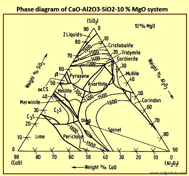
Fig 4 Phase diagram of CaO-Al2O3-SiO2-10 % MgO system
Slags with compositions in the region of 40 % SiO2, 48 % CaO, and 12 % A12O3 have low melting points, i.e., 1,300 deg C, and are appropriate for the control of sulphur and silicon in the hot metal. Frequently 6 % to 10 % MgO is used in place of an equivalent quantity of CaO to lower the viscosity of the slag. Small quantities of MnO, FeO, Na2O, and K2O etc. help to lower the melting point of the slag.
Essentially there are two slags in the furnace. The first is the ‘primary, or bosh, or early’ slag which is formed principally from the gangue constituents in the ores and agglomerates and CaO and MgO from the calcined fluxes, or the self-fluxing portions of the agglomerates. This slag is relatively basic compared to the final slag and contains some iron oxide. The ‘final or hearth’ slag is formed by the union of the early slag with constituents of the coke ash which are freed from the coke when it is burned before the tuyeres. This final slag continues to have its composition modified as it passes down into the hearth and mixes with liquid iron which also is flowing down into the crucible. There is an adjustment in the silica content of the slag, iron oxide can be reduced from it and it can absorb sulphur from the coke and liquid iron.
The formation of slags in the slag-formation zone is very furnace specific due to the impact of burden properties and furnace operation. 슬래그 형성 영역은 부하의 연화가 시작되는 응집 영역에서 시작하여 송풍구 표고 아래까지 계속됩니다. 따라서 슬래그 형성 영역에는 응집 영역, 활성 코크스 영역, 데드맨 및 레이스웨이가 포함됩니다. 슬래그 형성대 상부에 형성되는 슬래그를 '보시' 또는 '1차' 슬래그라고 하며, 하단의 영역을 떠나는 슬래그를 '로' 슬래그라고 합니다. The Primary slag is normally assumed to be made up of all burden slag components including the iron oxides not reduced in the granular zone, but does not include the ash from the coke or injected coal. 슬래그 조성은 가스에서 코크스회와 석탄회, 황 및 규소의 흡수 및 산화철의 환원으로 인해 노 내에서 하강함에 따라 변화합니다. 슬래그의 온도는 풍구 고도로 내려감에 따라 500℃ 정도 증가합니다. 이러한 조성과 온도의 변화는 슬래그의 물리적 특성, 특히 액상선 온도와 점도에 상당한 영향을 미칠 수 있습니다.
The slag produced in slag formation zone collects in the slag layer in the hearth zone, filling the voids in the hearth coke and ‘floating’ on the hot metal layer. 뜨거운 금속은 슬래그 층을 통과하여 뜨거운 금속 층에 도달합니다. The high surface area between the hot metal and slag as the hot metal passes through the slag layer enhances the kinetics of the chemical reactions. 이러한 반응은 뜨거운 금속 화학에 상당한 변화를 가져옵니다. In particular the (Si) and (S) contents prior to entering the slag layer are much higher than those in the hot metal layer.
제조공정
고로의 제철 공정에 대한 알칼리의 영향 고로(BF) 작동 중 주요 목표 중 하나는 최소 비용으로 원하는 화학 조성의 고온 금속(HM) 생산을 최대화하는 것입니다. 이를 위해서는 고품질의 원료 기반과 고로의 규칙적이고 원활한 작동이 필요합니다. 용광로에 들어가는 원치 않는 요소로 인해 발생하는 공정 문제를 피하기 위해 부하 재료의 품질이 매우 중요합니다. 이 영역에서 입력 전하의 원치 않는 요소의 내용에도 주의를 기울일 필요가 있습니다. 이러한 원치 않는 요소는 BF에 많은 기술적 문제를 일으킵니다. 또한 HM의 생산 비용에 큰
고로의 제철 이해 및 일본의 해부 연구 고로(BF) 제철은 주로 잘 정립되고 입증된 성능, 유연한 원료 사용 및 높은 열 에너지 보존 능력으로 인해 용선(HM)을 생산하는 가장 실용적인 수단입니다. BF 제철의 시작에 대한 정확한 날짜는 없습니다. 그러나 중요한 공정 설계와 재설계는 14세기부터 유럽의 제철로에서 구현되기 시작했습니다. 그 이후로 BF 루트는 다른 대체 철 생산 방법보다 선호하는 프로세스로 우세했습니다. 처음부터 BF 제철 공정은 지속 가능하고 실행 가능한 상태를 유지하기 위해 매우 효율적인 공정이 되기 위해