

제조공정

산업 제조
 |
| × | 1 | |||
 |
| × | 1 | |||
 |
| × | 6 | |||
| × | 2 | ||||
| × | 1 | ||||
| × | 1 | ||||
| × | 4 | ||||
 |
| × | 1 | |||
| × | 2 | ||||
| × | 2 | ||||
 |
| × | 1 | |||
| × | 1 | ||||
 |
| × | 3 |
| ||||
 |
|
 |
| |||
 |
| |||
|
Instructables Wheel Contest에서 1등상, Instructables Arduino Contest에서 2등상, 그리고 Instructables Design for Kids Challenge에서 2위를 차지했습니다. 투표해주신 모든 분들께 감사드립니다!!!
http://www.instructables.com/id/Joy-Robot-Rob%C3%B4-Da-Alegria-Open-Source-3D-Printed-A/
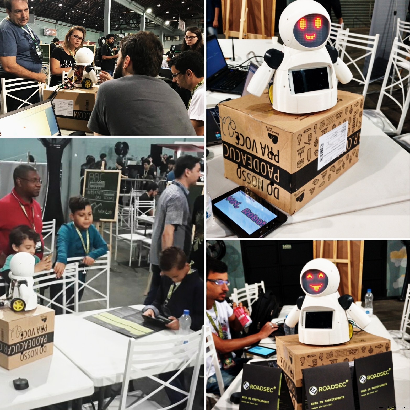
로봇은 도처에 있습니다. 산업 응용에서 수중 및 우주 탐사에 이르기까지. 하지만 내가 가장 좋아하는 것들은 재미와 오락에 사용되는 것들입니다! 이 프로젝트에서 DIY 로봇은 어린이 병원에서 오락용으로 사용하도록 설계되어 어린이들에게 즐거움을 선사합니다. 이 프로젝트는 어린이 병원에서 자선 활동을 수행하는 NGO를 지원하기 위해 지식을 공유하고 기술 혁신을 촉진하는 데 중점을 두고 있습니다.
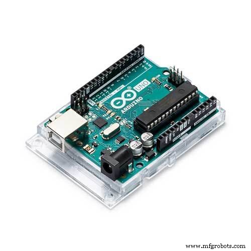
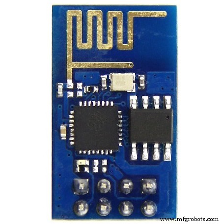
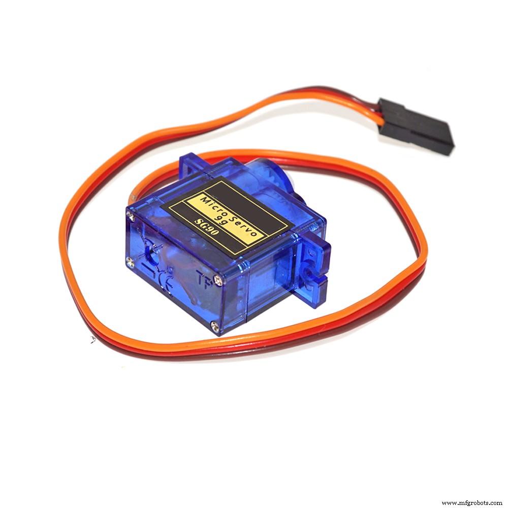
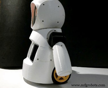
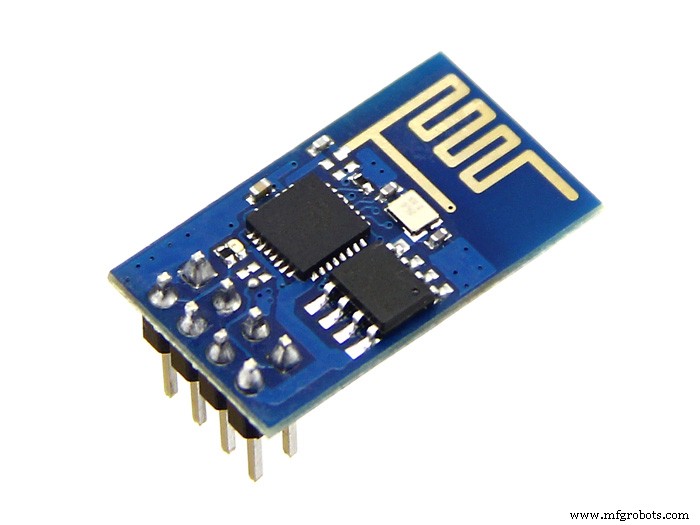
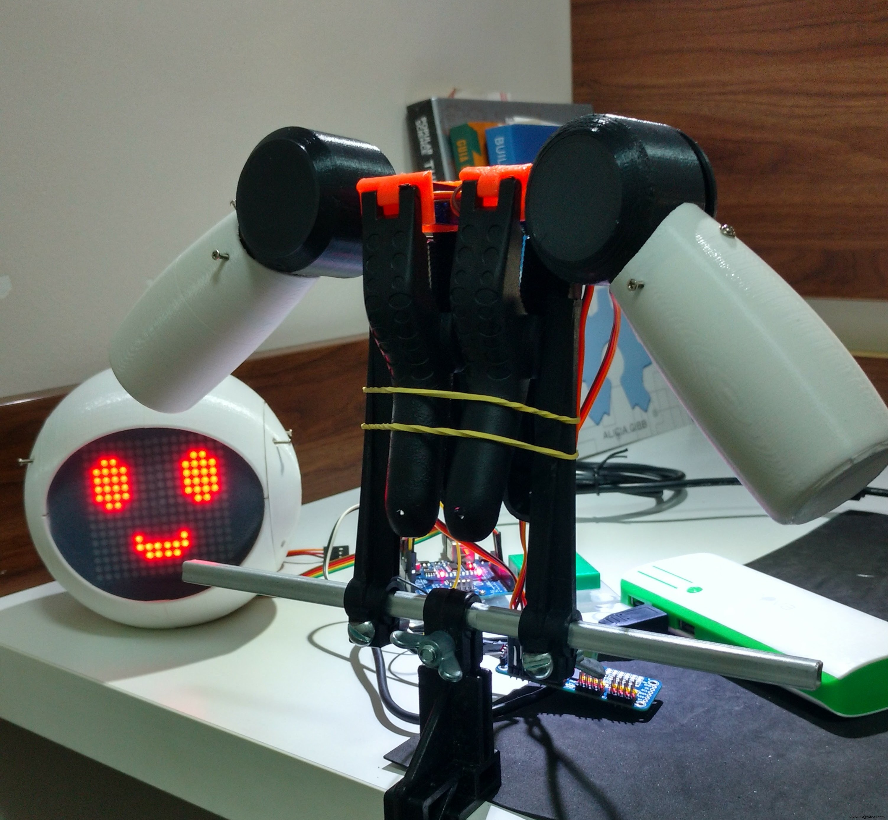
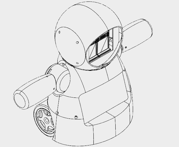
이 튜토리얼에서는 ESP8266 Wi-Fi 모듈에 연결된 Arduino Uno를 사용하여 Wi-Fi 네트워크를 통해 제어되는 원격 작동 휴머노이드 로봇을 설계하는 방법을 보여줍니다. 그것은 머리와 팔의 움직임을 형성하는 일부 서보 모터, 작은 거리를 이동하기 위한 일부 DC 모터 및 LED 매트릭스로 만든 면을 사용합니다. 로봇은 HTML로 설계된 인터페이스를 사용하여 일반 인터넷 브라우저에서 제어할 수 있습니다. Android 스마트폰은 로봇에서 작업자의 제어 인터페이스로 비디오 및 오디오를 방송하는 데 사용됩니다.
이 튜토리얼은 로봇의 구조가 3D 프린팅되고 조립되는 방법을 보여줍니다. 전자회로를 설명하고, 아두이노 코드를 자세하게 설명하여 누구나 로봇을 복제할 수 있습니다.
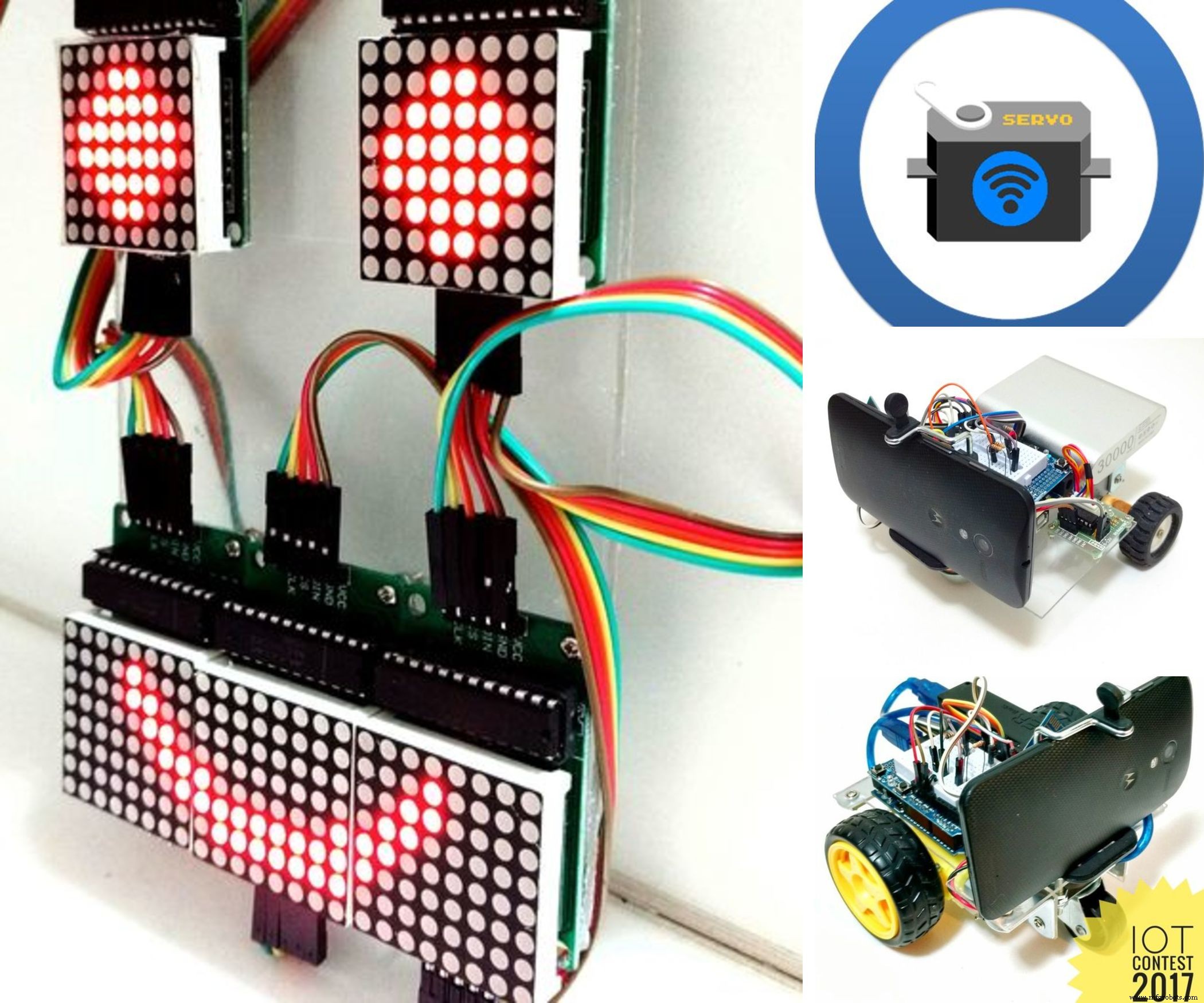
이 로봇에 사용된 기술 중 일부는 이미 자습서에 게시되었습니다. 다음 자습서를 살펴보십시오.
<울>위에서 언급한 프로젝트와 관련된 다른 팀원들에게 특별히 감사드립니다. 이 튜토리얼에서 제공하는 코드의 첫 번째 버전을 책임지고 있습니다.
<울>프로젝트에 대해 자세히 알아보기:
<울>
어떻게 도와드릴까요?
이 프로젝트는 팀원과 일부 기업의 소액 기부로 자금을 조달합니다. 마음에 드셨다면 저희를 도울 수 있는 몇 가지 방법이 있습니다:
<울>Creality CR10mini를 단 $349.99에 구입할 수 있다는 사실을 알고 계셨습니까? 쿠폰 코드 사용 cr10mini3d Gearbest에서 다운로드:http://bit.ly/2FZ5OXw
1단계:약간의 역사...
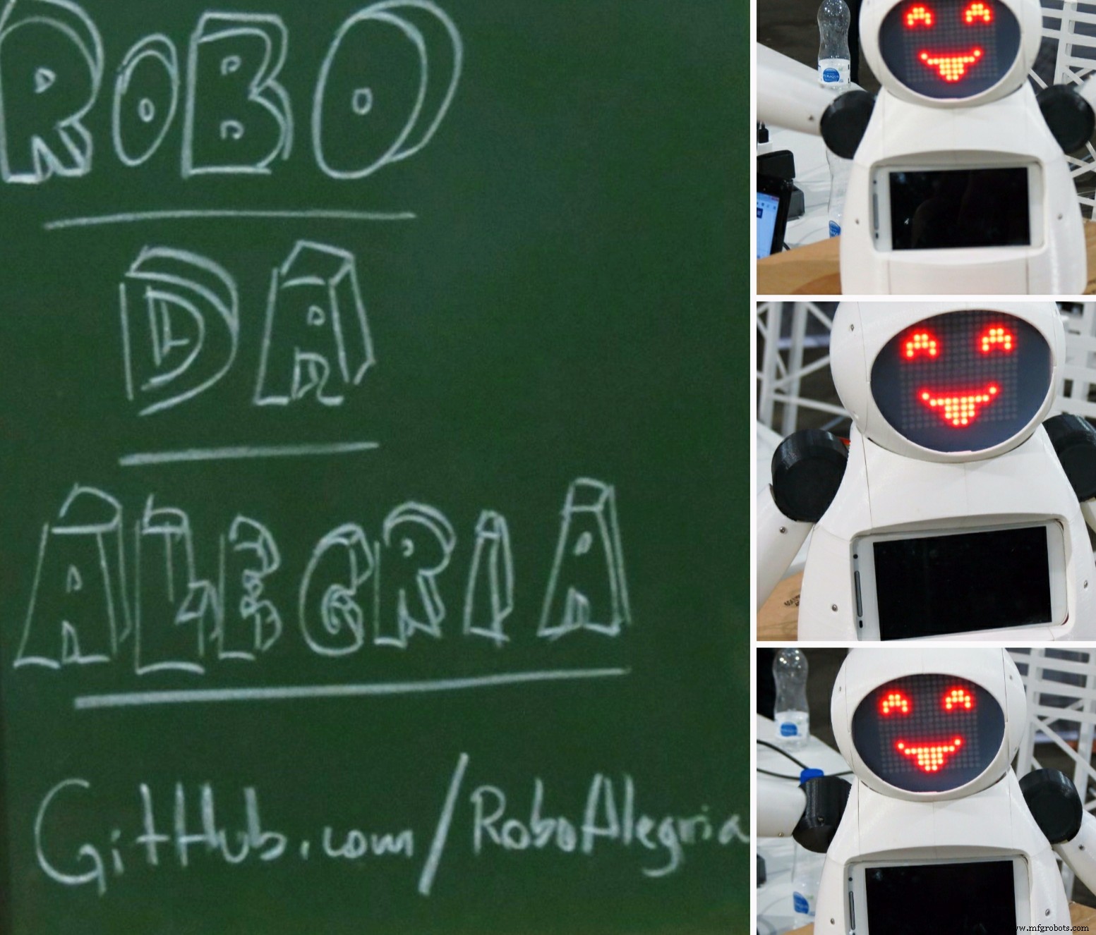

'Robô da Alegria'('Joy Robot') 프로젝트는 기술 개발과 메이커 운동에 커뮤니티를 유치하는 것을 목표로 2016년 브라질 Baixada Santista 지역에서 태어났습니다. 어린이 병원에서 NGO가 수행하는 자발적인 프로젝트에서 영감을 받은 이 프로젝트는 개방형 하드웨어와 apen 소프트웨어 도구를 사용하여 어린이 병원 환경에 약간의 재미를 주고 다른 조직의 작업에 기여할 수 있는 로봇을 개발하고자 합니다.
이 프로젝트의 씨앗은 2015년 말에 심어졌습니다. Baixadas Santista(ASEBS)의 Startups of Startups에서 추진하는 기술의 생성 및 개발에 대한 대화 후. 그것은 상금 없이 이상적인 프로젝트였지만 사람들이 다른 사람들을 돕는 것을 목표로 이타적인 방식으로 참여하는 주제를 제시했습니다.
로봇은 초기 개념부터 현재까지 다양한 변형을 거쳤습니다. 기계식 눈과 눈썹이 있는 단 하나의 머리에서 현재의 인간형 형태에 이르기까지 여러 건설 재료와 전자 장치를 테스트하면서 여러 번 반복 작업을 수행했습니다. 아크릴 프로토타입과 레이저 절단 MDF에서 우리는 3D 프린팅 바디로 옮겼습니다. 블루투스로 제어되는 2개의 서보 모터가 있는 단순한 인터페이스에서 6개의 서보 모터와 2개의 모터로 구성된 본체까지 Wi-Fi 네트워크를 사용하는 웹 인터페이스를 통한 DC 명령.
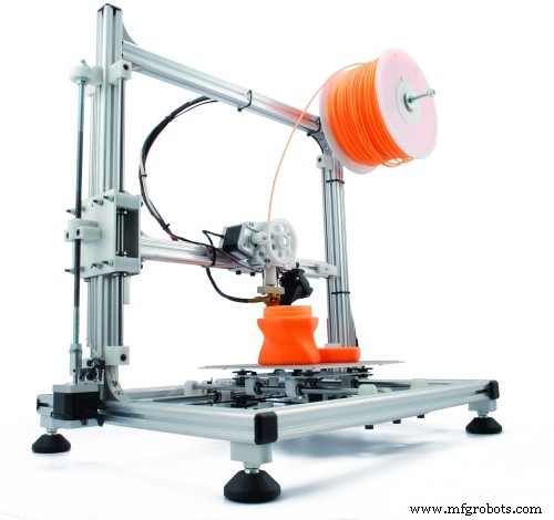
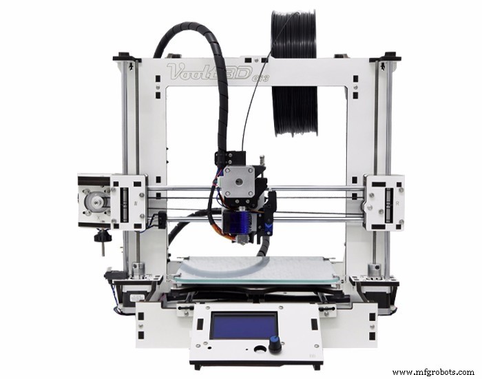
로봇 구조는 전체가 Fusion 360을 사용하여 3D 프린팅으로 제작되었습니다. 프린터의 최대 사용 시간이 관건인 메이커 스페이스나 팹랩에서 로봇 레플리카를 제작할 수 있도록 로봇의 디자인을 여러 조각으로 나누었습니다. 각각 인쇄하는 데 3시간 미만입니다. 부품 세트는 본체 장착을 위해 접착되거나 볼트로 고정됩니다.
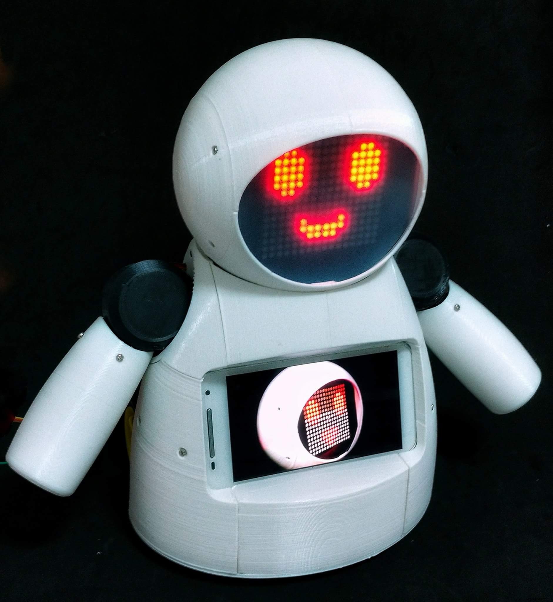
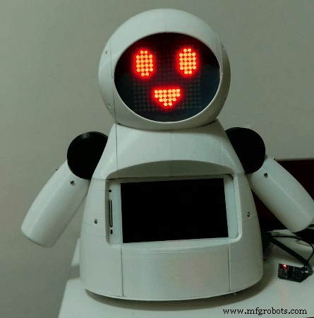
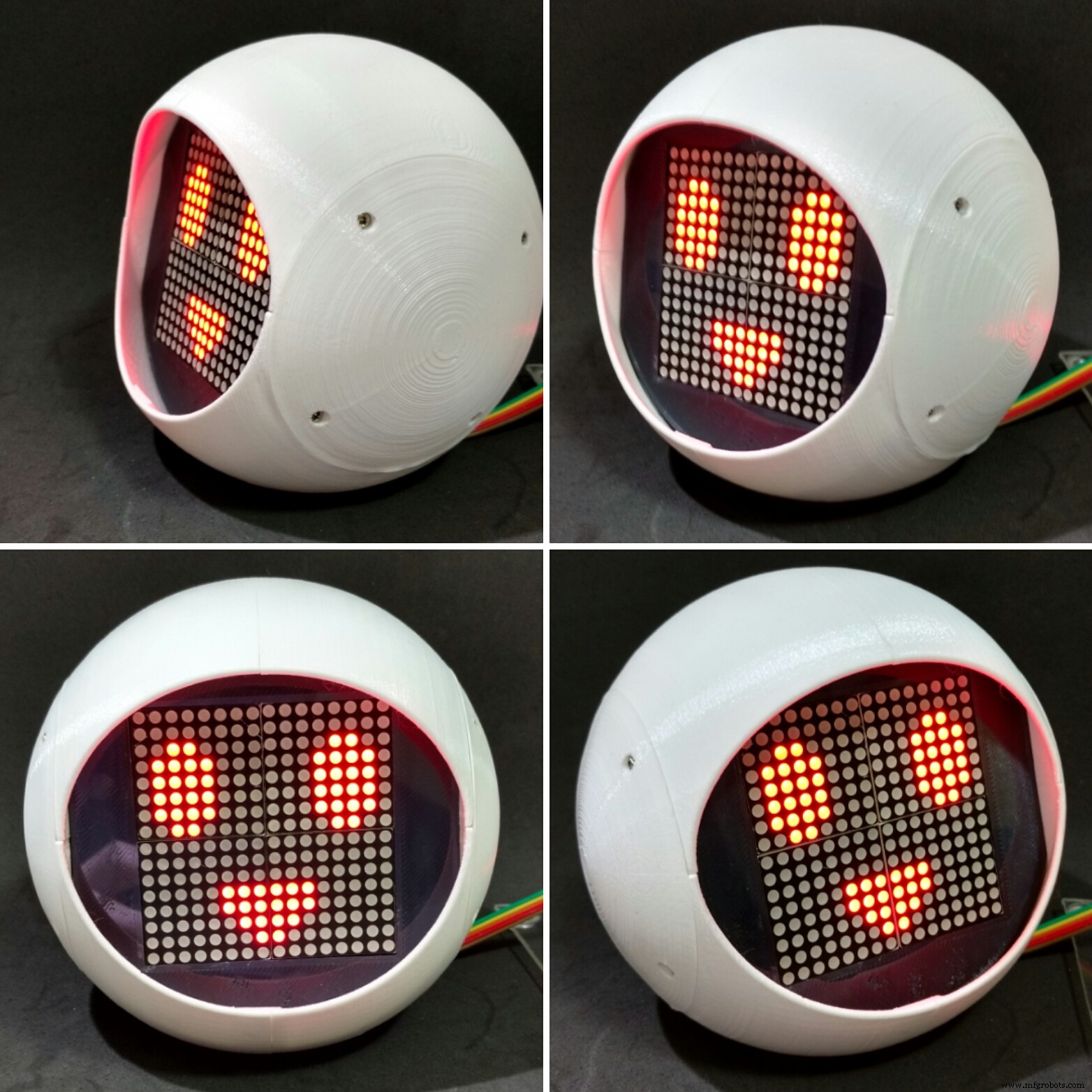
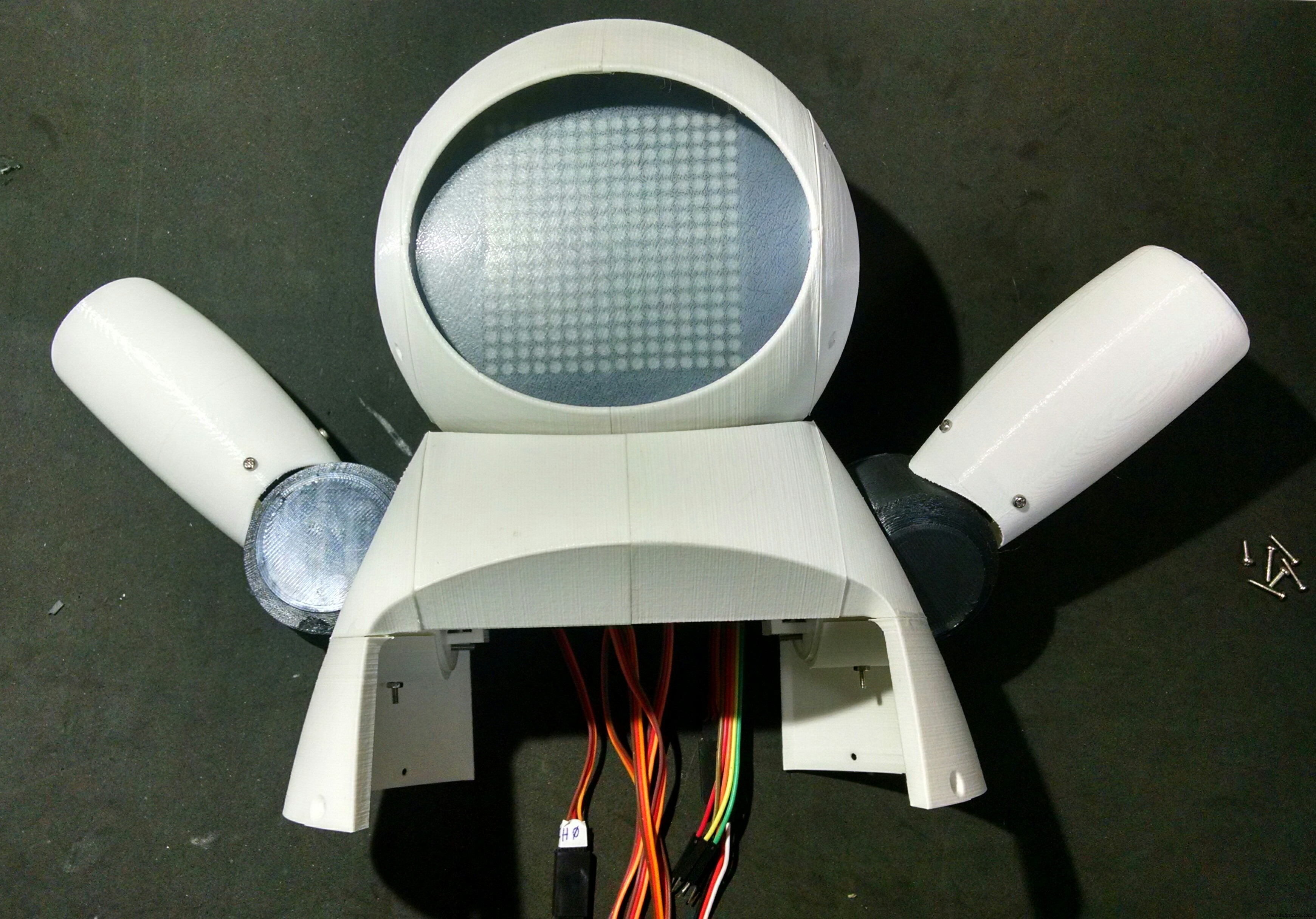
LED 어레이로 구성된 얼굴은 로봇에게 감정을 표현할 수 있는 능력을 부여합니다. 서보 모터로 구동되는 팔과 목은 사용자와 상호 작용하는 데 필요한 이동성을 작은 자동 장치에 제공합니다. 로봇의 제어 센터에서 Arduino Uno는 ESP8266 모듈과의 통신을 포함하여 모든 주변 장치와 인터페이스하므로 사용자가 동일한 Wi-Fi 네트워크에 연결된 모든 장치를 통해 표정과 움직임을 명령할 수 있습니다.
또한 로봇의 가슴에는 스마트폰이 설치되어 있어 로봇 조작자와 어린이 간의 음성 및 영상 전송에 사용됩니다. 장치 화면은 로봇 본체와 상호 작용하도록 설계된 게임 및 기타 응용 프로그램과의 상호 작용에 계속 사용할 수 있습니다.
2단계:도구 및 재료
이 프로젝트에 사용된 도구와 자료는 다음과 같습니다.
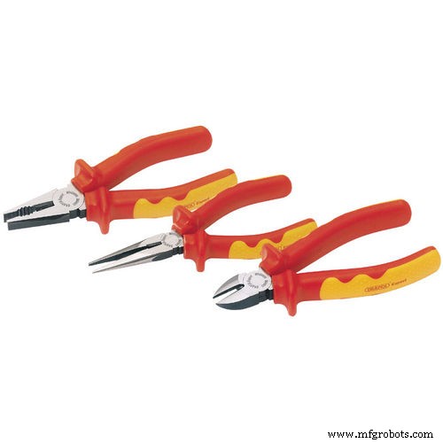
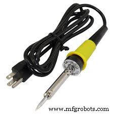
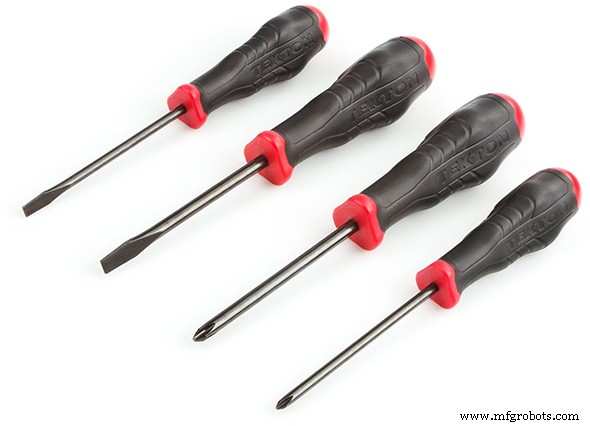
도구:
<울>전자제품 :
<울>역학:
<울>위의 링크는 이 튜토리얼에서 사용된 항목을 찾고 이 프로젝트의 개발을 지원할 수 있는 위치에 대한 제안입니다. 다른 곳에서 자유롭게 검색하고 좋아하는 지역 또는 온라인 상점에서 구입하십시오.
Creality3D CR10mini를 단 $349.99에 구입할 수 있다는 사실을 알고 계셨습니까? Gearbest에서 쿠폰 코드 cr10mini3d를 사용하고 받으세요:http://bit.ly/2FZ5OXw
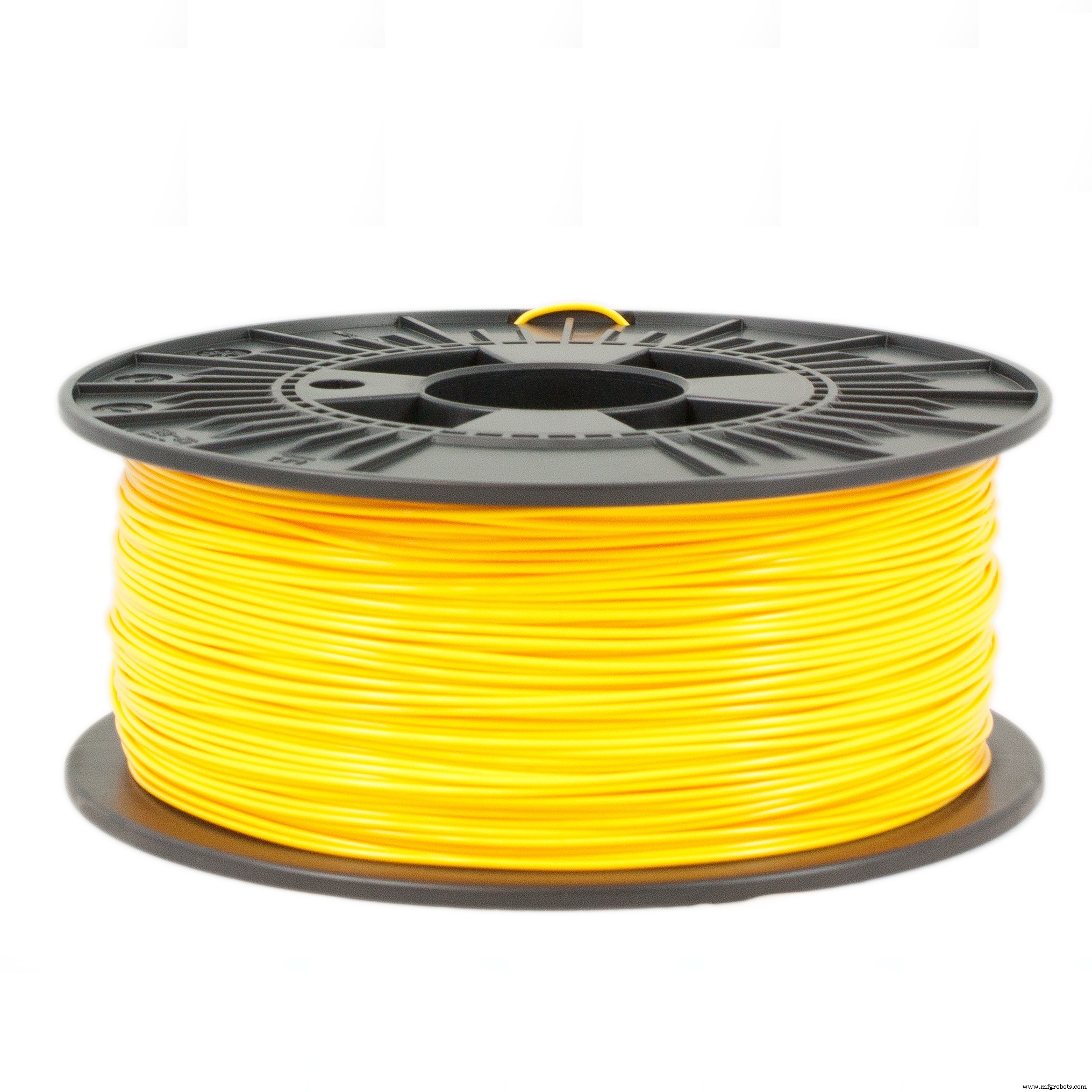
3단계:3D 프린팅

로봇 구조는 모두 Autodesk Fusion 360을 사용하여 3D 프린팅으로 제작되었습니다. 프린터의 최대 사용 시간이 중요한 메이커 스페이스 또는 팹 랩에서 로봇 복제본을 생산할 수 있도록 로봇 설계를 조각으로 나누었습니다. 각각 인쇄하는 데 3시간 미만입니다. 부품 세트는 본체 장착을 위해 접착되거나 볼트로 고정됩니다.
모델은 36개의 서로 다른 부분으로 구성됩니다. 대부분은 지지대 없이 10% 인필로 인쇄되었습니다.
<울>로봇을 장착하는 절차는 다음 단계에 설명되어 있습니다.
다음 웹사이트에서 모든 stl 파일을 다운로드할 수 있습니다.
<울>이것은 실험적인 프로토타입입니다. 일부 부품에는 일부 개선이 필요합니다(프로젝트의 이후 업데이트를 위해). 몇 가지 알려진 문제가 있습니다.
<울>3D 프린터가 없는 경우 다음과 같이 할 수 있습니다.
<울>
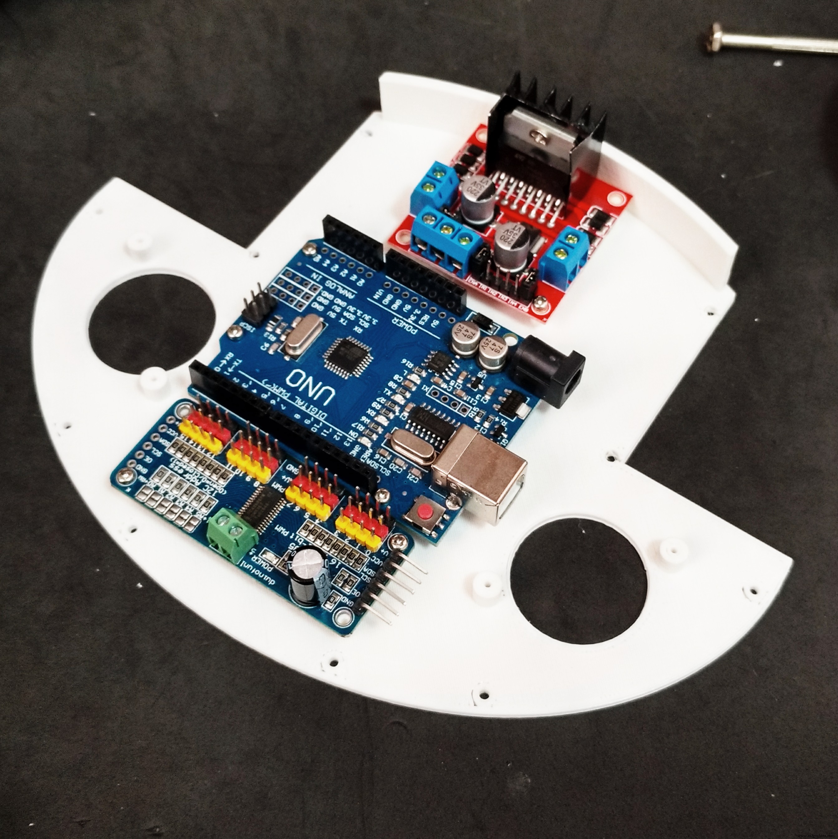
4단계:회로 개요
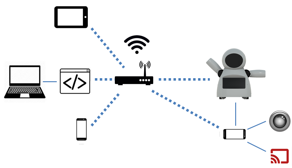
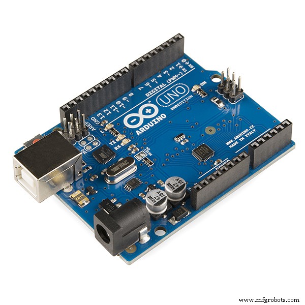
로봇은 핵심에서 Arduino Uno를 사용하여 제어됩니다. Arduino는 Wi-Fi 네트워크를 통해 로봇을 원격 제어하는 데 사용되는 ESP8266-01 모듈과 인터페이스합니다.
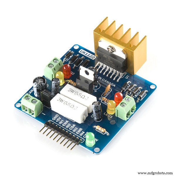
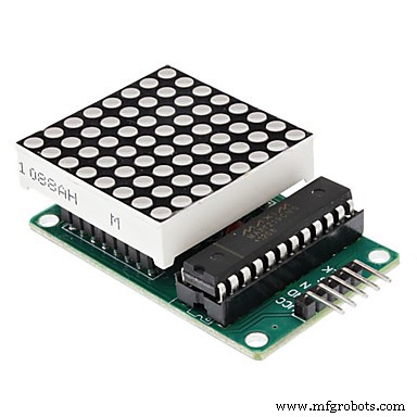
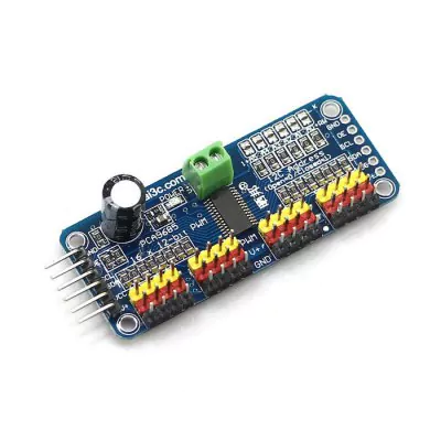
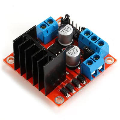
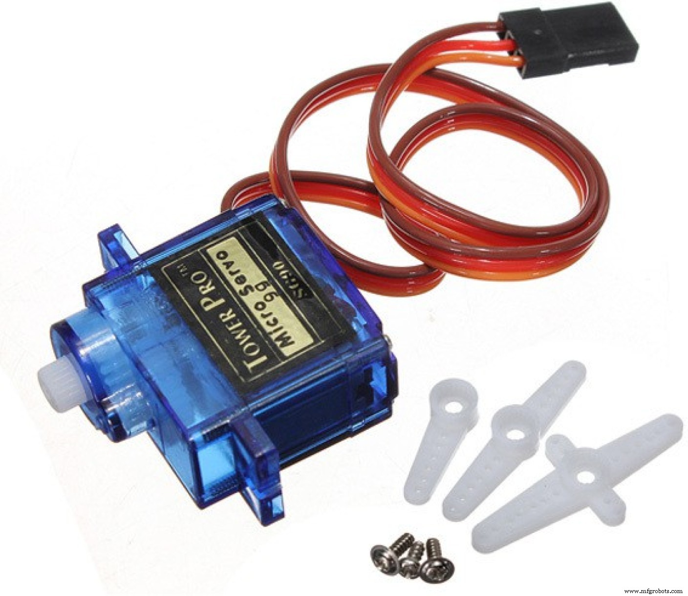
16채널 서보 컨트롤러는 I2C 통신을 사용하여 Arduino에 연결되고 6개의 서보 모터(목에 2개, 팔에 2개)를 제어합니다. 5개의 8x8 LED 매트릭스 어레이는 Arduino에 의해 전원이 공급되고 제어됩니다. 4개의 Arduino의 디지털 출력은 h-bridge를 사용하여 2개의 DC 모터를 제어하는 데 사용됩니다.
회로는 두 개의 USB 전원 은행을 사용하여 전원이 공급됩니다. 하나는 모터용이고 다른 하나는 Arduino용입니다. 신호 파워 팩을 사용하여 전체 로봇에 전원을 공급하려고 했습니다. 그러나 ESP8266은 DC 모터를 켜고 끌 때 스파이크로 인해 연결이 끊어지곤 했습니다.
로봇의 가슴에는 스마트폰이 있습니다. 일반 컴퓨터에서 호스팅되는 제어 인터페이스와 비디오 및 오디오를 브로드캐스트하는 데 사용됩니다. 또한 ESP6288에 명령을 보내 로봇 본체를 제어할 수도 있습니다.
여기에 사용된 구성 요소가 목적에 맞게 최적화되지 않았을 수 있습니다. 예를 들어 Arduino + ESP8266 조합 대신 NodeMCU를 사용할 수 있습니다. 카메라가 있는 랩스베리 파이는 스마트폰을 대체하고 모터도 제어합니다. 안드로이드 스마트폰을 로봇의 "두뇌"로 사용하는 것도 가능합니다. 그것은 사실입니다... Arduino Uno는 매우 접근하기 쉽고 모든 사람이 사용하기 쉽기 때문에 선택되었습니다. 이 프로젝트를 시작할 즈음에는 ESP와 Raspberry Pi 보드가 우리가 사는 곳에서 여전히 상대적으로 비쌌습니다... 일단 우리가 저렴하게 로봇을 만들고 싶었고, 아두이노 보드는 그 순간 최고의 선택이었습니다.
로봇%2Bmk0%2B-%2Brev8_Esquem_C3_A1tico.pdf 로봇%2Bmk0%2B-%2Brev8_bb.pdf
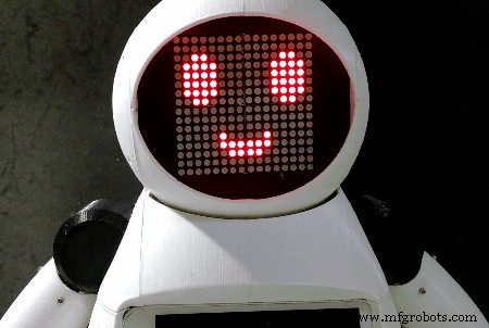
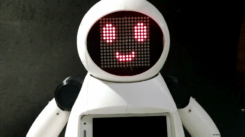
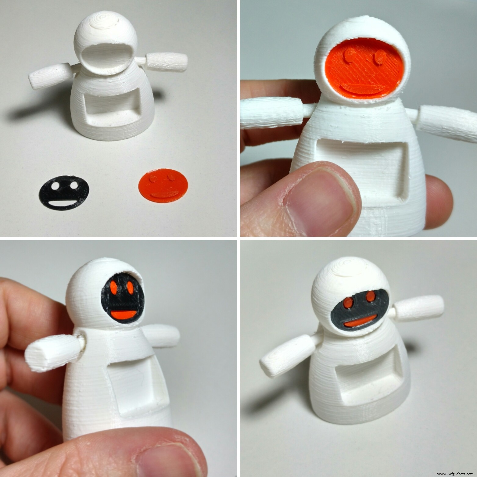
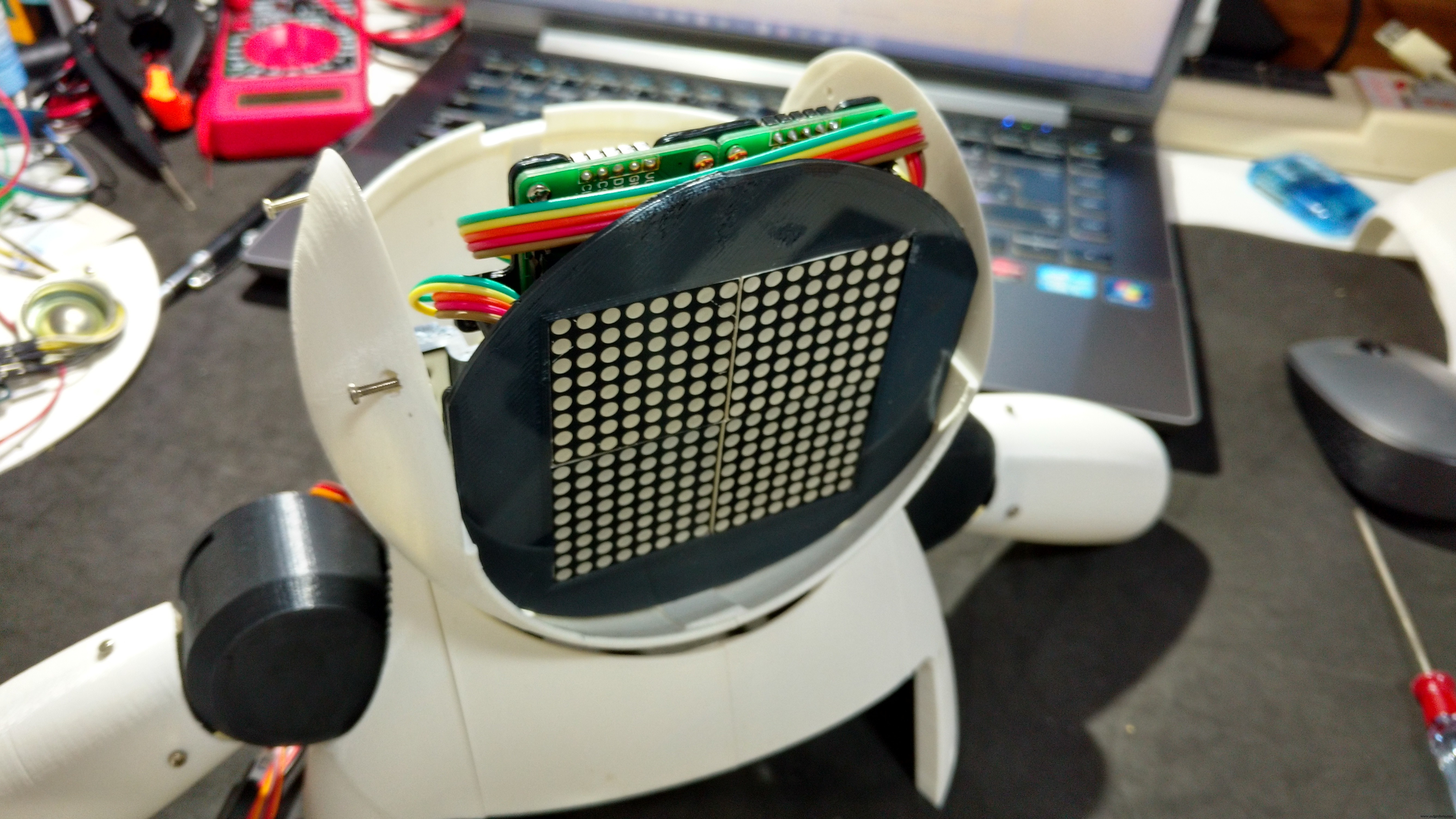
5단계:얼굴 조립
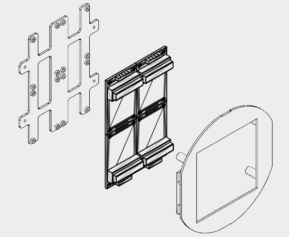
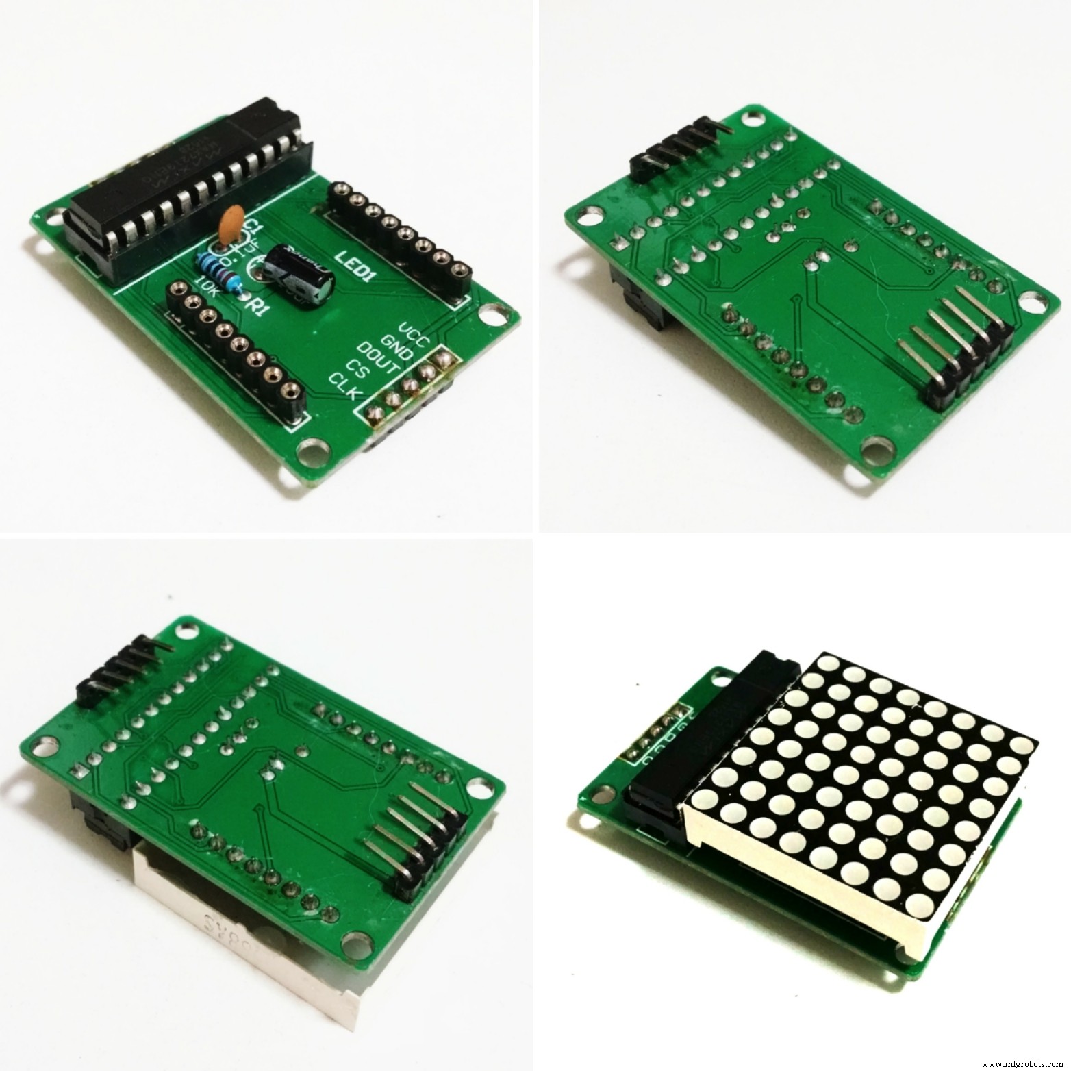

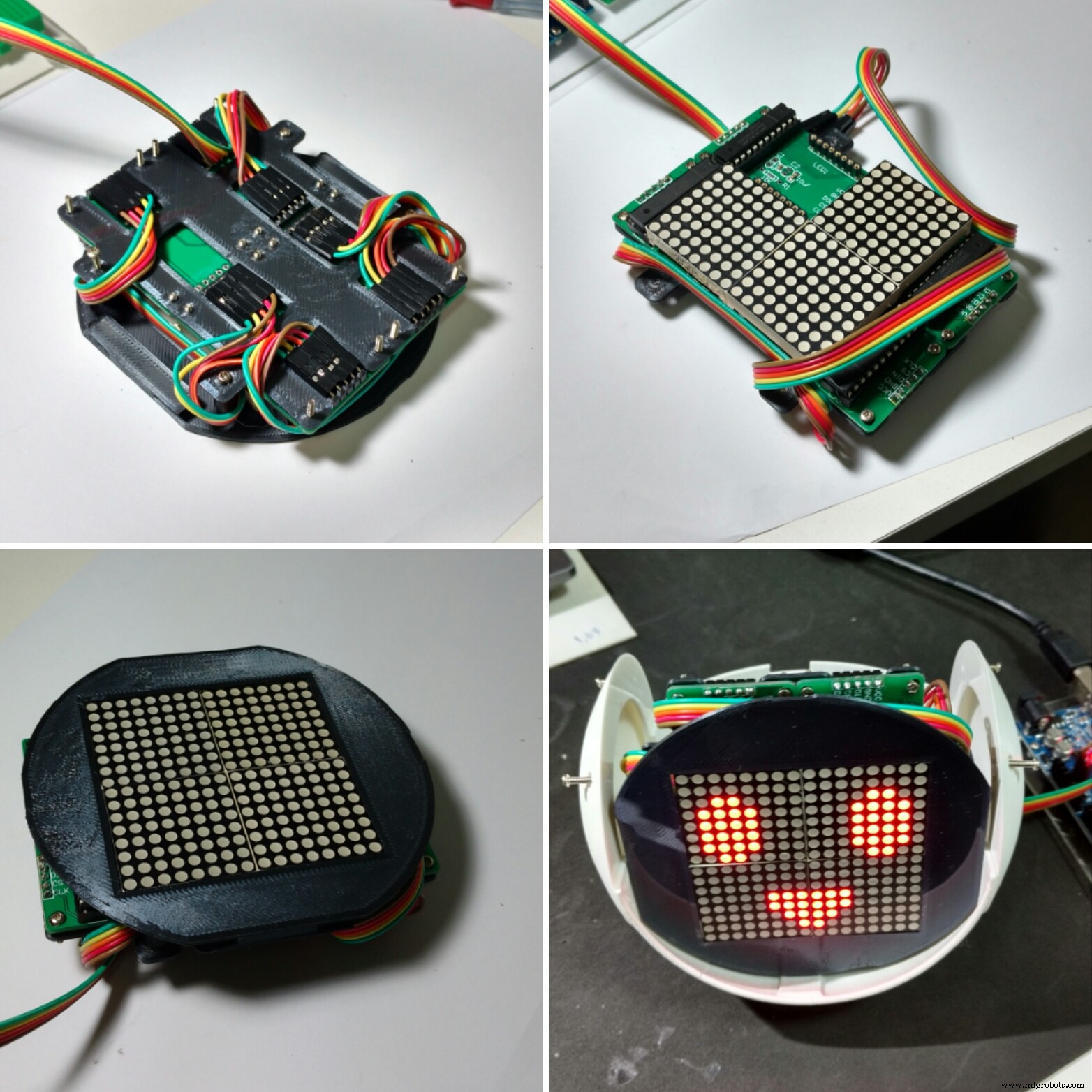
4개의 8x8 LED 매트릭스가 로봇의 얼굴에 사용되었습니다.
구조는 검은색 PLA를 사용하여 3D 인쇄된 두 부분(후면 플레이트 및 전면 전면 플레이트)으로 분할되었습니다. 3D 프린팅에 약 2.5시간이 걸렸습니다. 10% 채우기와 지지대 없이 말이죠.
공간 제한으로 인해 LED 매트릭스의 커넥터는 납땜을 제거하고 위치를 아래 설명된 대로 변경해야 했습니다.
<울>이미지에서 최종 결과를 확인할 수 있습니다.
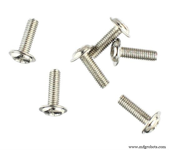
그런 다음 4개의 LED 매트릭스를 16개의 M2x6mm 볼트를 사용하여 백플레이트에 부착했습니다. 핀은 회로도에 따라 연결되었습니다.
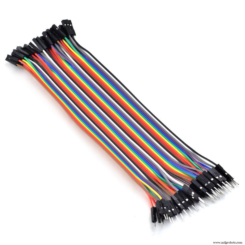
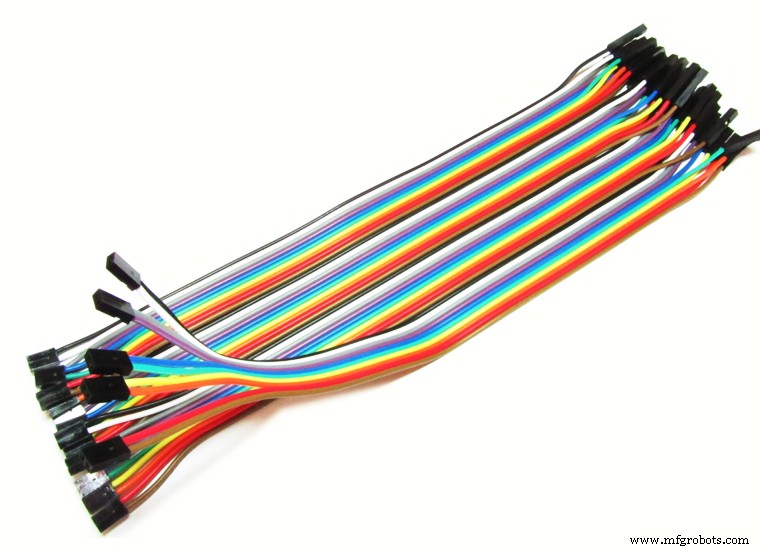
첫 번째 매트릭스는 5선식 암-수 점퍼를 사용하여 연결되었습니다. 남성 끝은 나중에 Arduino 핀에 연결되었습니다. 암 끝은 매트릭스 입력 핀에 연결됩니다. 각 매트릭스의 출력은 암-암 점퍼를 사용하여 다음 매트릭스의 입력에 연결됩니다.
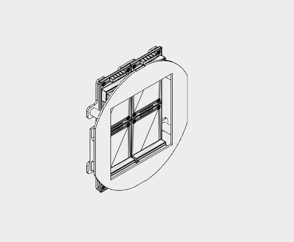
매트릭스 연결 후 전면 플레이트는 4개의 M2 볼트를 사용하여 설치됩니다. 느슨한 전선이 없도록 점퍼를 후면 및 전면 패널에 감습니다.
얼굴 모듈은 다음 단계에서 설명하겠지만 나중에 로봇의 머리 내부에 설치됩니다.
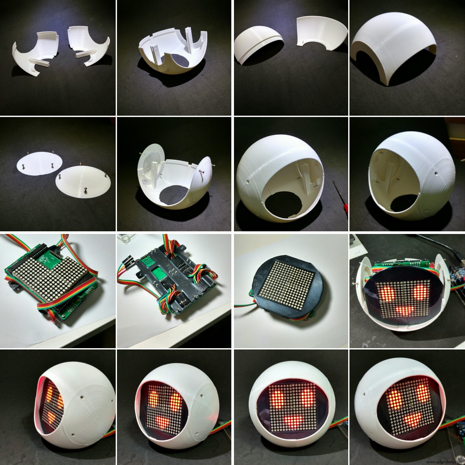
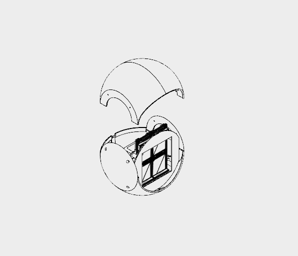
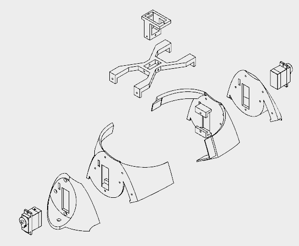
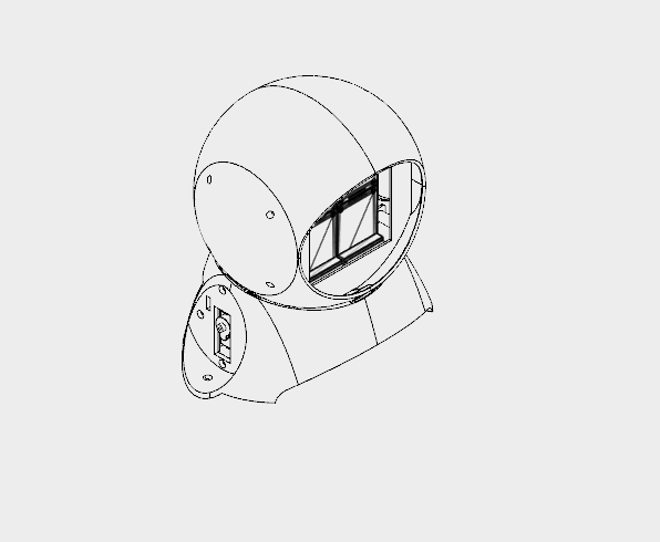
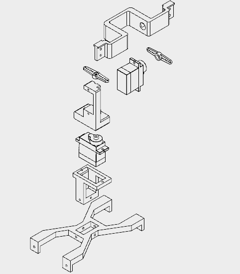
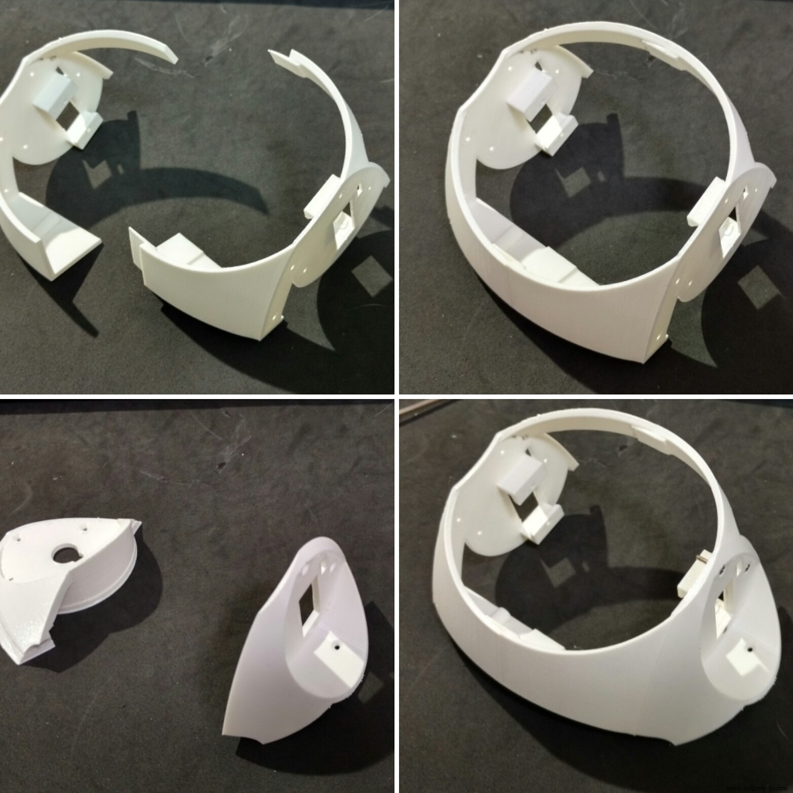
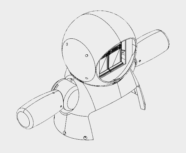
6단계:헤드 장착
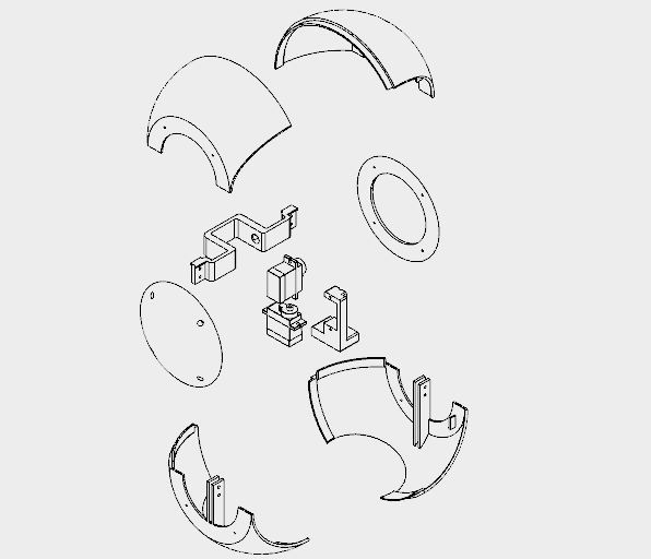
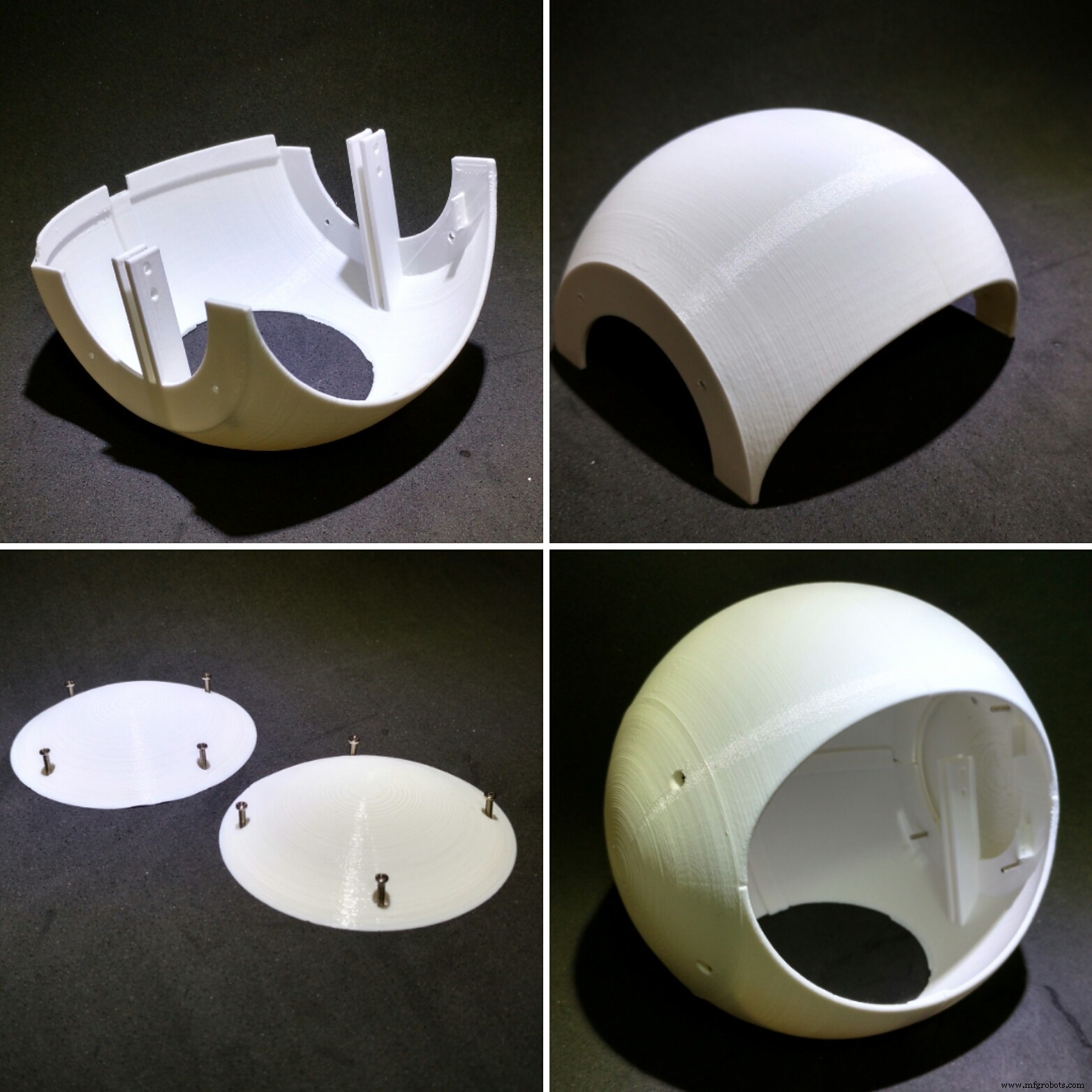
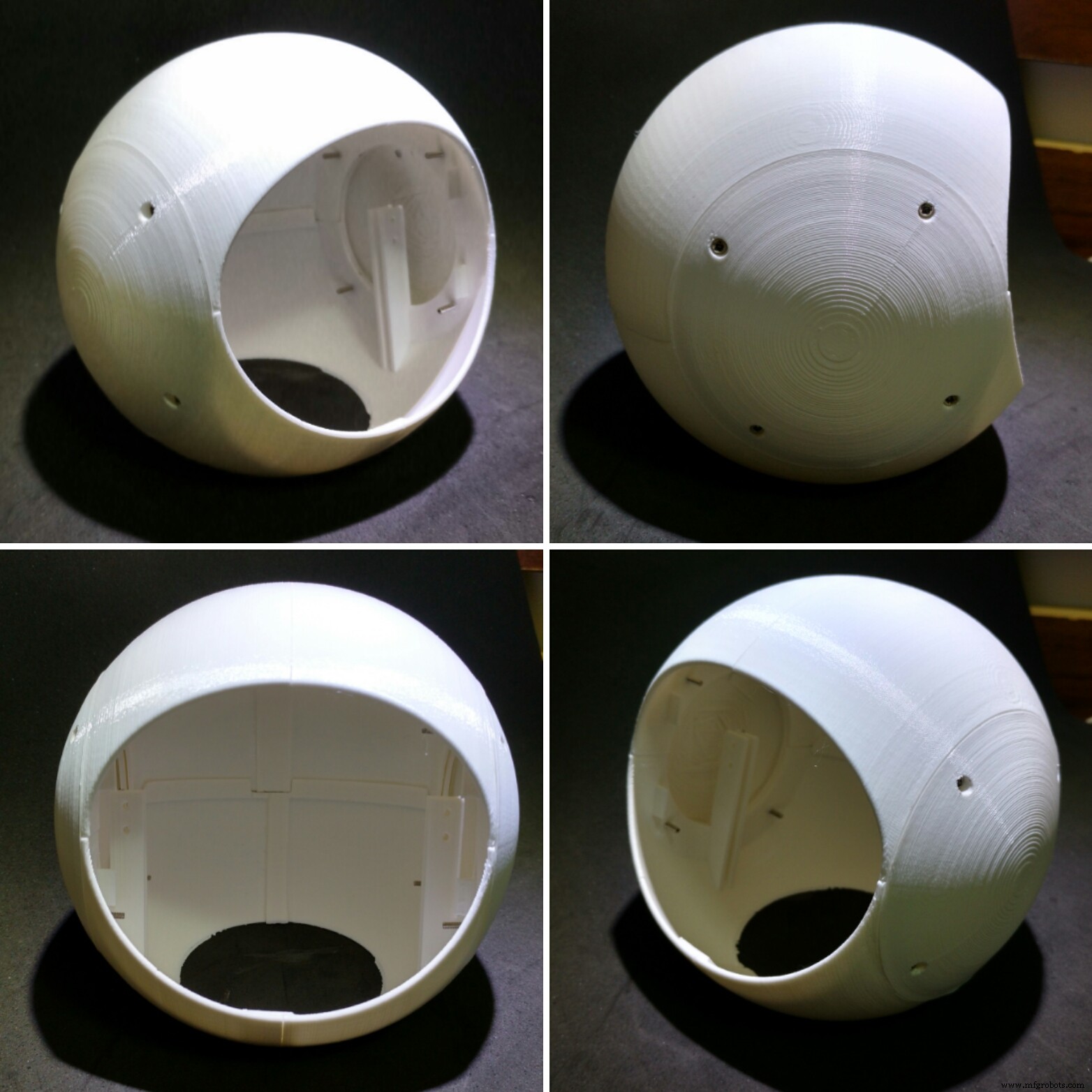

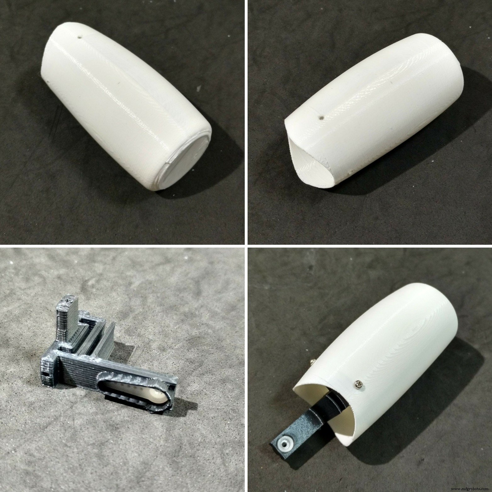
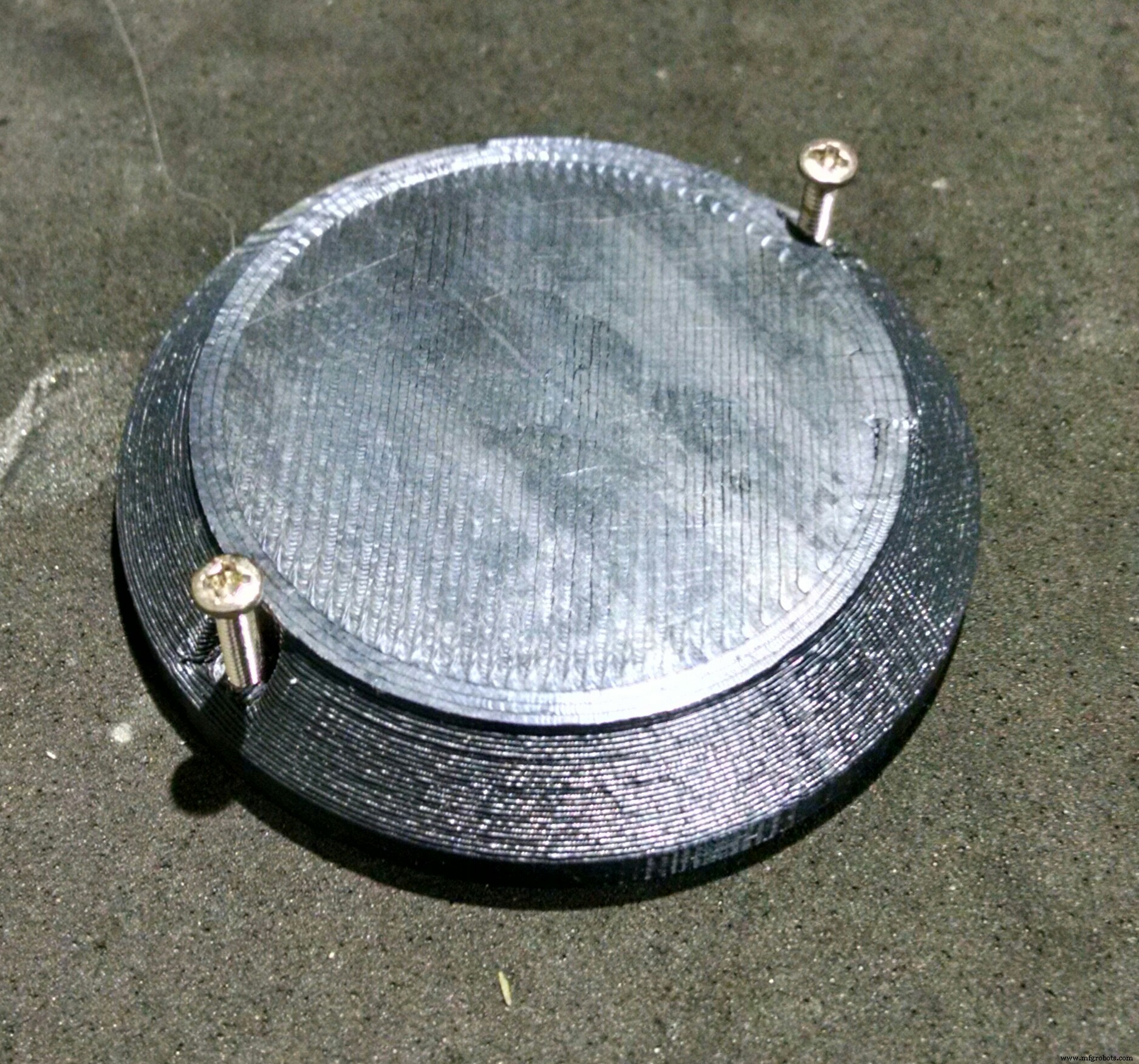
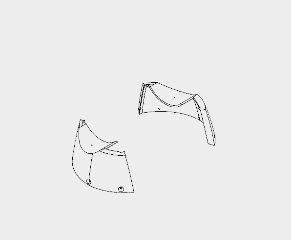
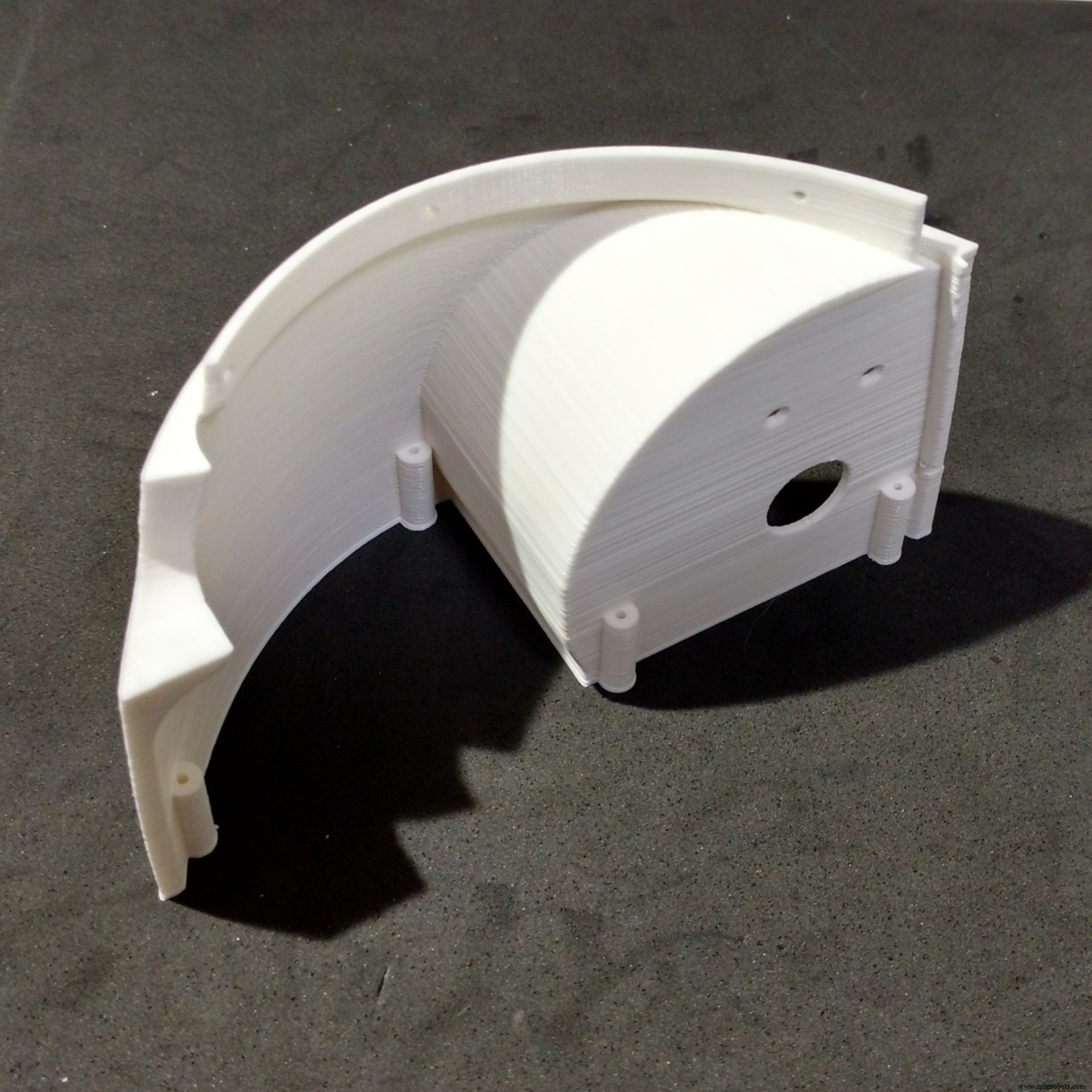
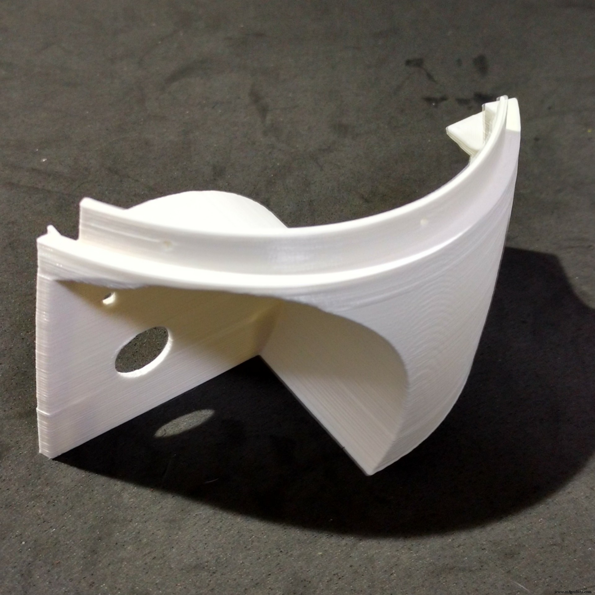
로봇의 머리는 8개의 3D 프린팅 부품으로 분할되었으며, 모두 0.2mm 해상도, 10% 인필 및 지지대가 없는 흰색 PLA로 프린팅되었습니다.
<울>직경 130mm 구조를 인쇄하는 데 거의 18시간이 걸렸습니다.
머리의 상단과 하단은 두 부분으로 나뉩니다. 그들은 슈퍼 접착제를 사용하여 함께 붙어 있습니다. 접착제를 바르고 몇 시간 동안 그대로 두십시오.
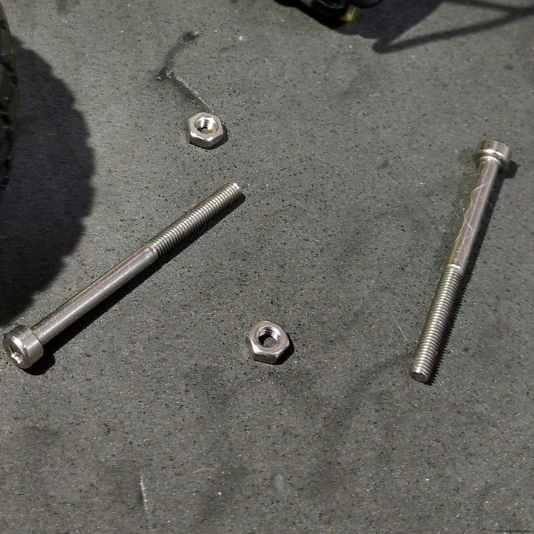
그런 다음 헤드의 상단과 하단 측면에 부착된 볼트를 사용하여 측면 캡을 장착합니다. 이런 식으로 헤드 상단 부품에 부착된 나사를 제거하여 헤드를 분해하여 수리할 수 있습니다. 머리를 닫기 전에 로봇의 얼굴(이전 단계에서 설명)과 흉상(다음 단계에서 설명)을 조립합니다.
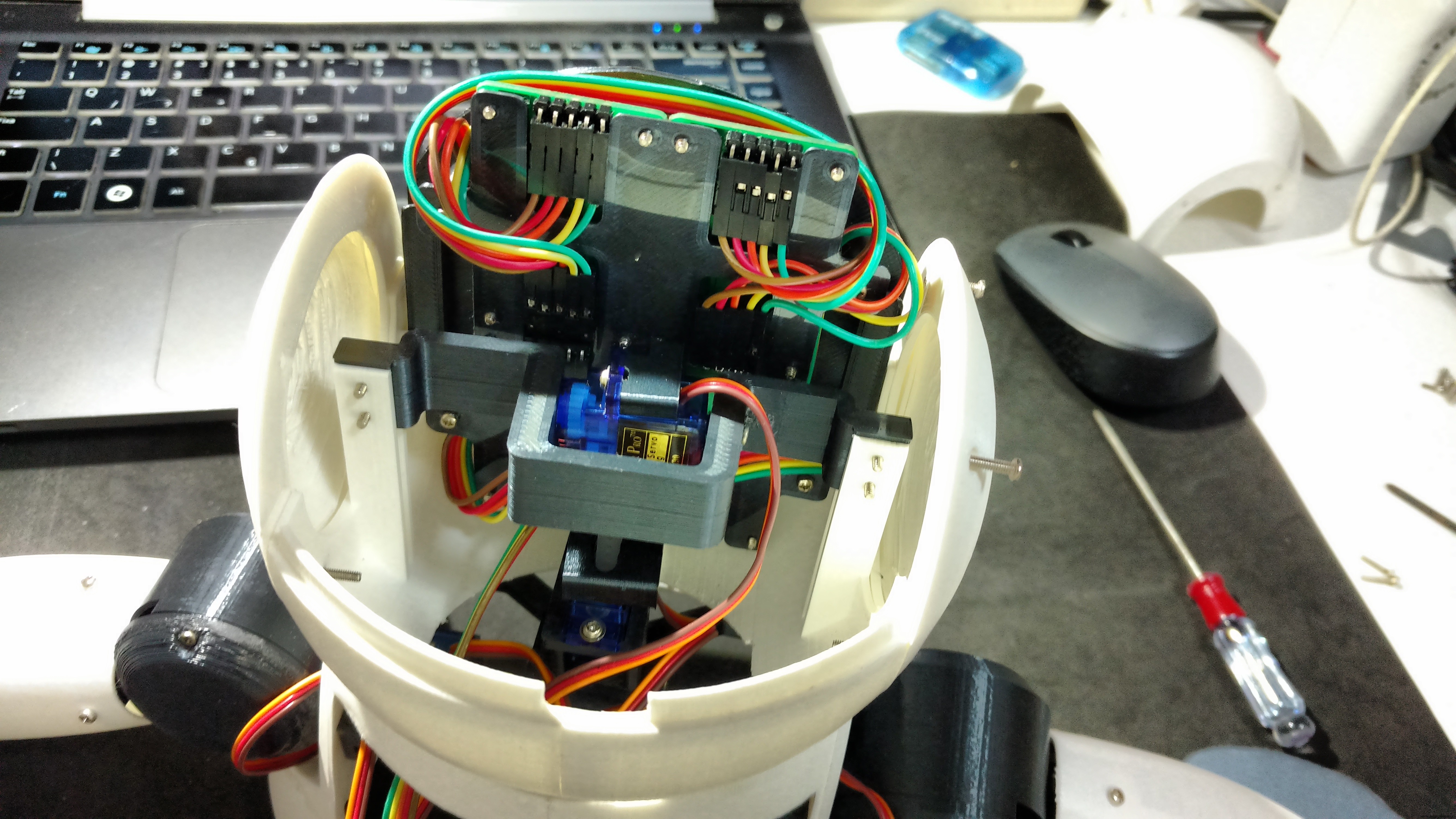
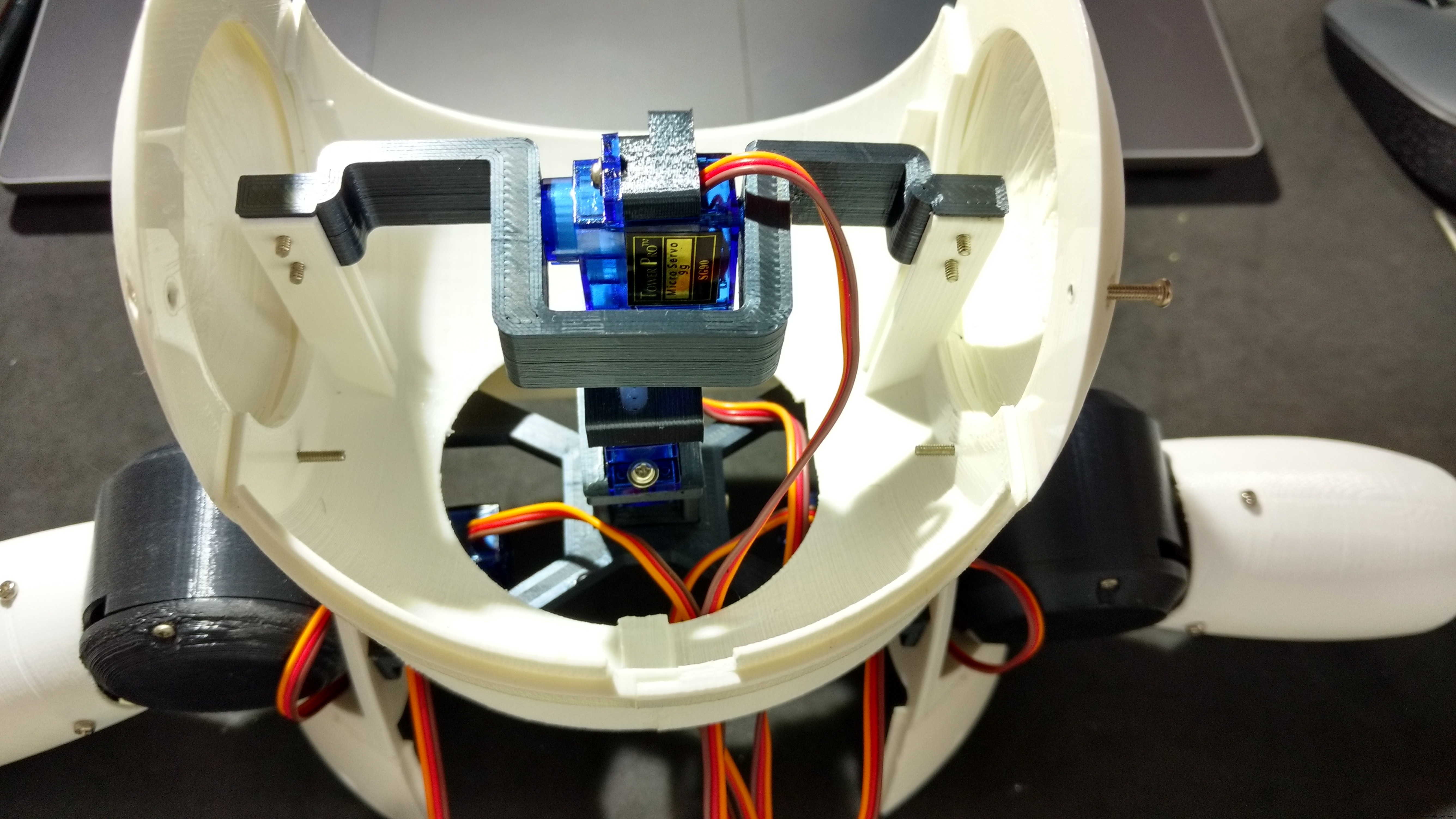
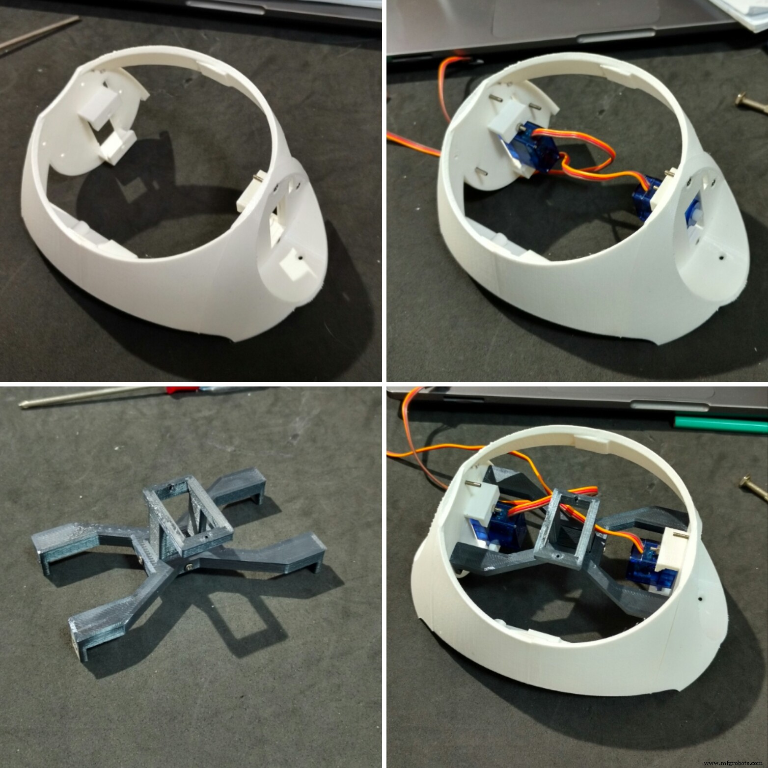
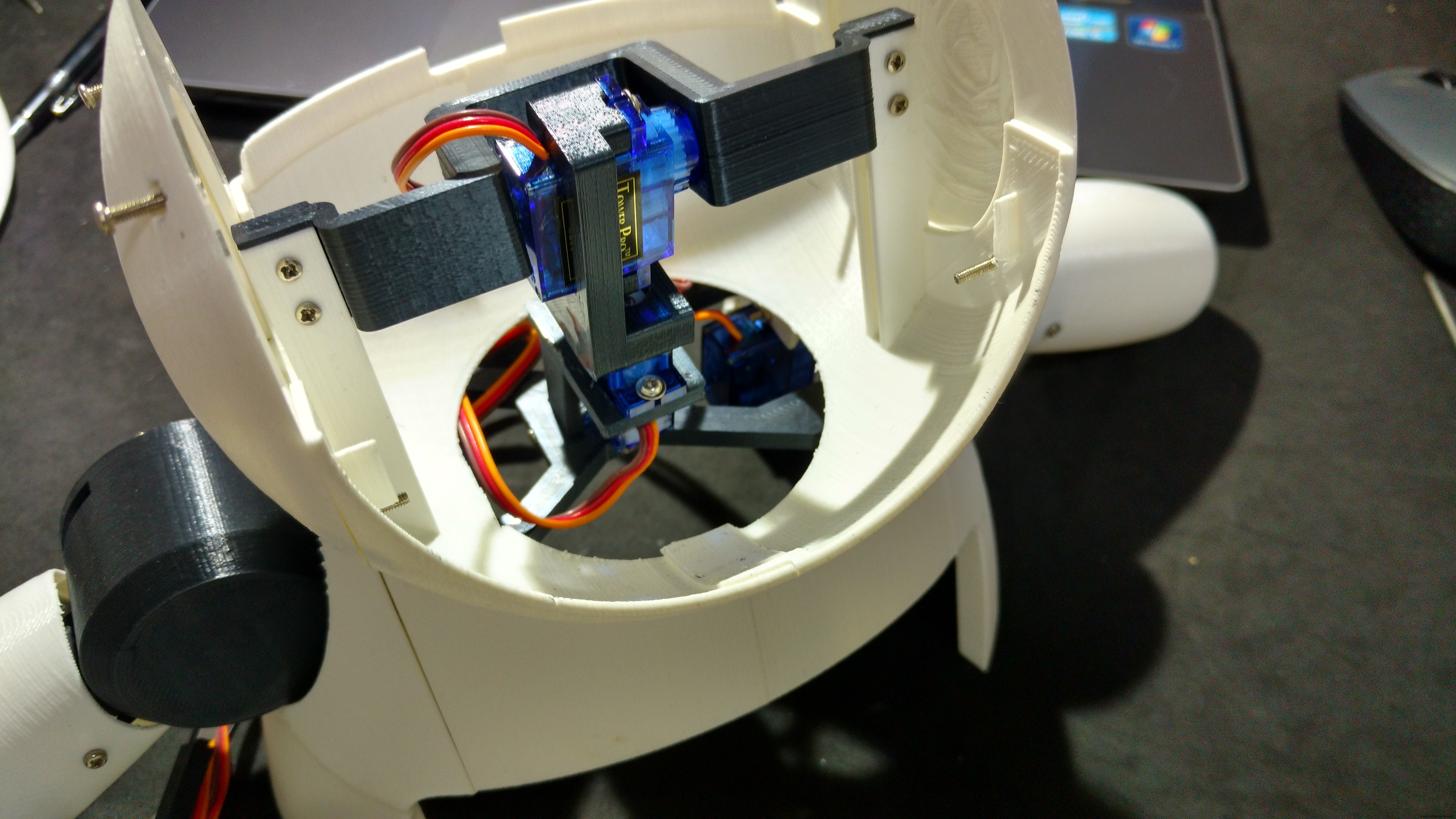
5번 서보 모터를 Neck 축 1에 부착했습니다. 서보를 축 중앙에 위치시킨 다음 Horn을 부착하고 나사를 사용하여 위치를 고정했습니다. 두 개의 M2x6mm 볼트를 사용하여 해당 서보 모터에 Neck 축 2를 장착했습니다. 6번 서보모터도 같은 방법으로 Neck 축 2에 부착합니다.
목 축 2는 다음 단계에서 볼 수 있듯이 나중에 목 중심에 연결되었습니다.
페이스 모듈은 헤드 내부에 장착되어 있습니다.
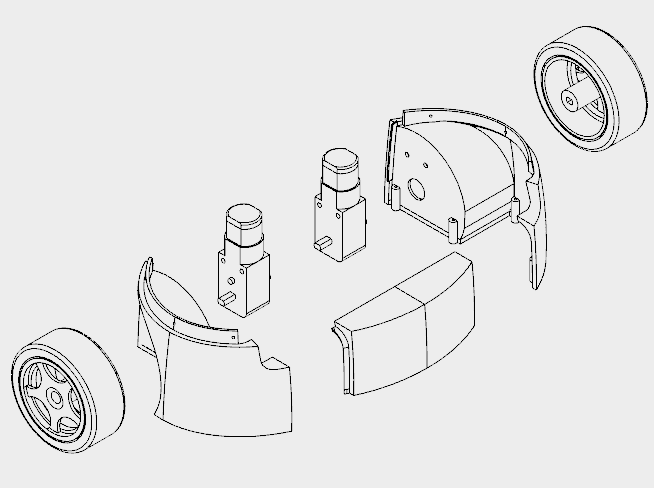
7단계:버스트 및 숄더 조립
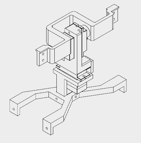

가슴과 어깨 부분을 인쇄하는 데 약 12시간이 걸렸습니다.
이 섹션은 다섯 가지 부분으로 구성되어 있습니다.
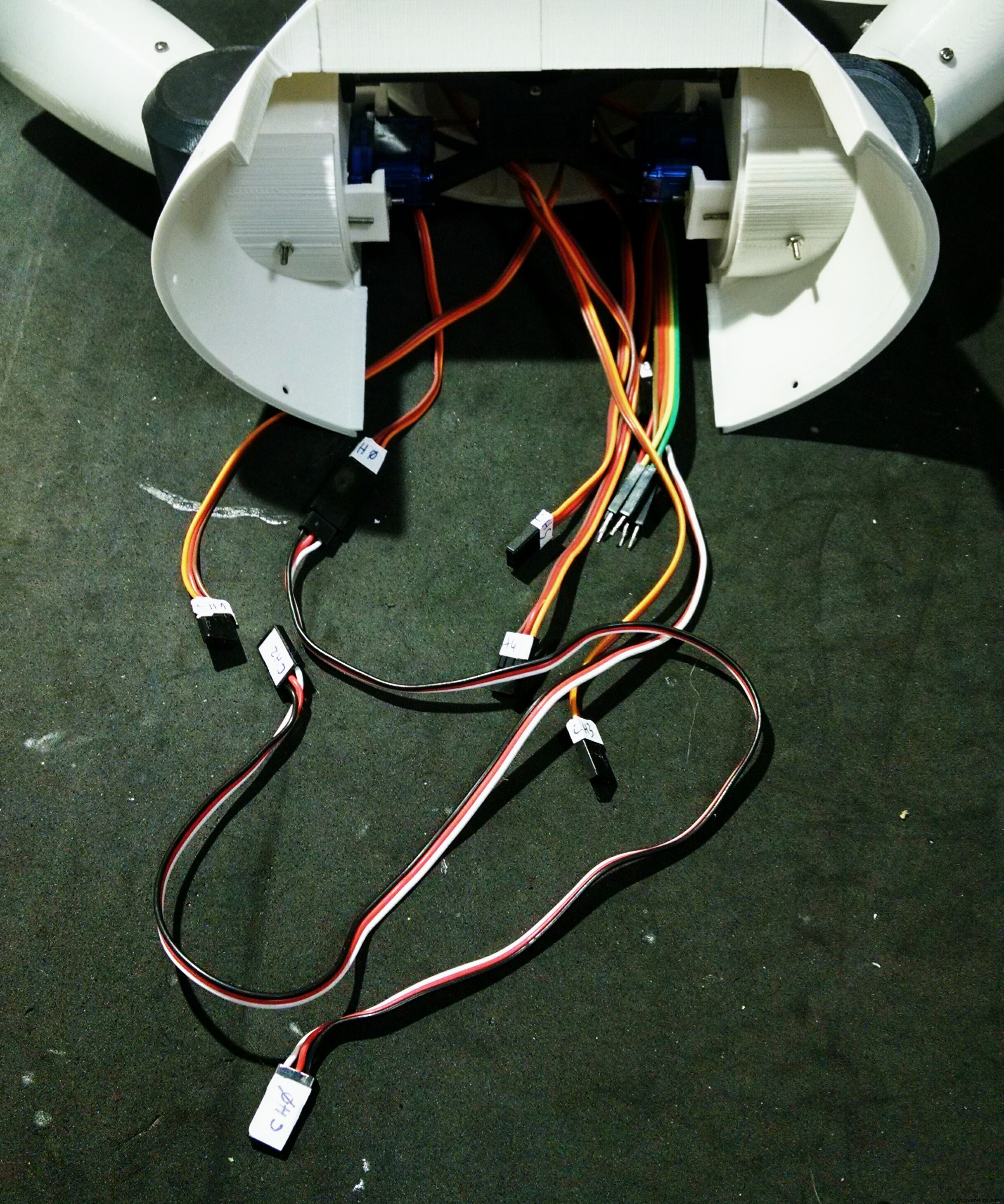
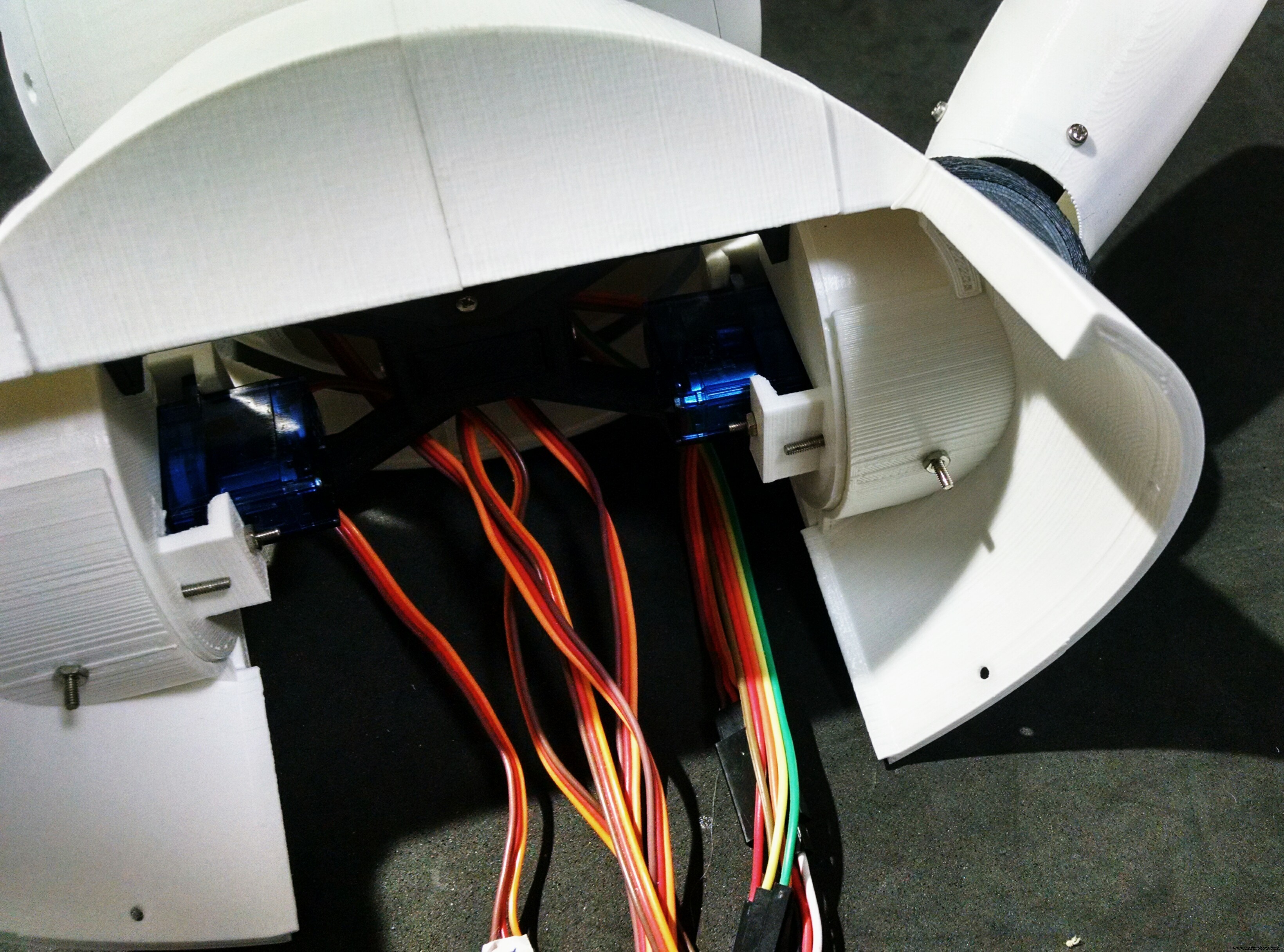
<울>흉상 부분은 슈퍼 글루를 사용하여 접착되었습니다. M2x10mm 볼트를 사용하여 측면에 숄더를 부착하고 양쪽에 서보모터(서보모터 #2, #4)를 설치하였다. 그들은 양쪽 어깨에 있는 직사각형 구멍(와이어는 실제로 통과하기가 매우 어렵습니다)을 통과하고 M2x10mm 볼트와 너트를 사용하여 부착됩니다.
센터 넥에는 넥 축 3 부분이 삽입되는 직사각형 구멍이 있습니다. 4개의 M2x6mm 볼트가 이 두 부품을 연결하는 데 사용되었습니다. 그 후 센터 넥이 어깨에 부착되었습니다. 그것은 가슴에 어깨를 장착하는 데 사용되는 것과 동일한 볼트를 사용합니다. 4개의 M2x1,5mm 너트는 위치를 잠그는 데 사용됩니다.
서보 모터 #6은 두 개의 나사를 사용하여 Neck 축 3에 연결되었습니다. 그런 다음 Neck 중앙 직사각형 구멍 안에 Neck 축 3을 설치하고 4개의 M2x6mm 볼트를 사용하여 위치를 고정했습니다.
8단계:암 조립

각 팔을 인쇄하는 데 약 5시간이 걸렸습니다.
각 암은 네 부분으로 구성되어 있습니다.
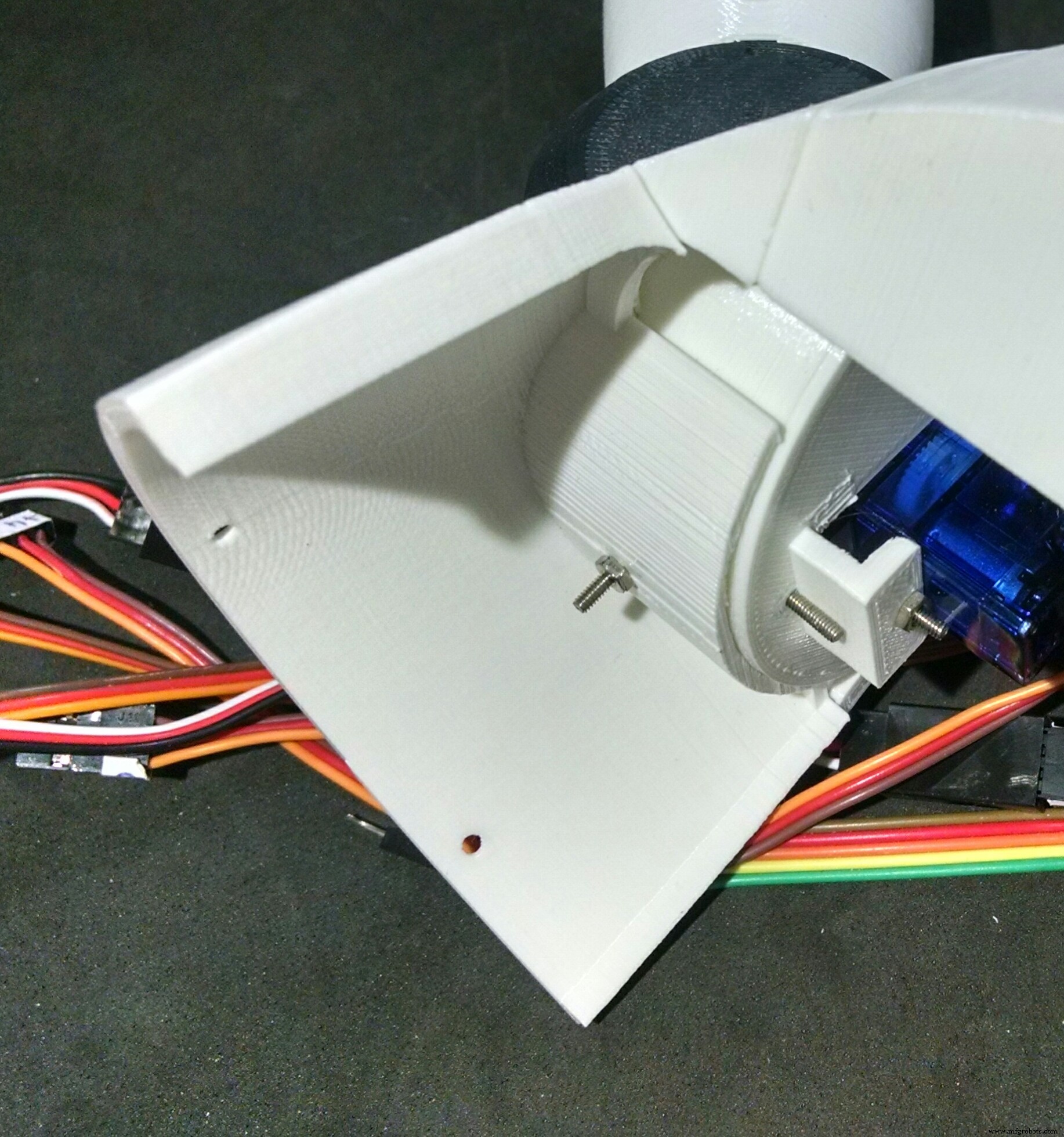
<울>암 축은 중앙 집중식이며 3개의 M2x6mm 볼트를 사용하여 암 자체에 장착됩니다. 축의 다른 쪽 끝에는 서보 혼이 부착되어 있습니다.
서보모터(#1, #3)는 약간의 나사를 사용하여 숄더 컵 내부에 설치되고 뿔(암 축에 부착된 하나)이 설치됩니다. 컵에 다른 혼을 설치하기 위한 구멍이 있는데, 이 구멍은 이전 단계에서와 같이 어깨에 이미 장착된 서보(#2, #4)에 부착되어 있습니다.
There's another hole on the Cup (and on the Shoulder) for passing the cables of the servos. After that, the Cap is installed to close the shoulder of the robot, with two M2x6mm bolts.
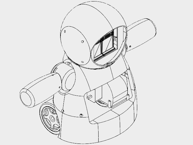
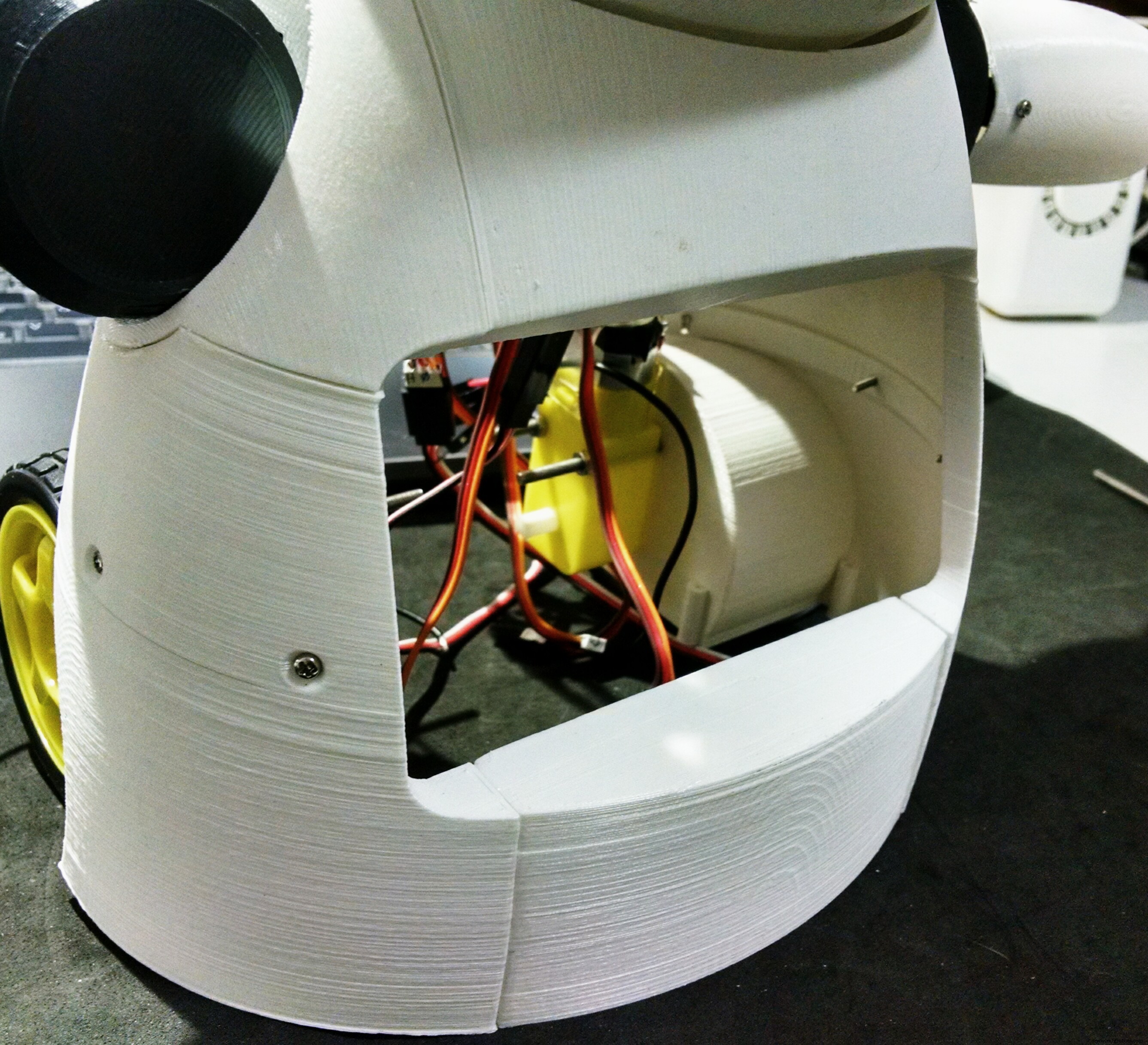
Step 9:Mounting the Chest
The chest is the part that links the bust to the bottom (wheels and base) of the robot. It's made of only two parts (right and left parts. I printed them in 4 hours.
The shoulders of the robot fits on upper part of the chest. There is a hole for a bolt that helps the alignment and fixation of thos parts. Although it's recomended to glue those two parts.
The bottom of this parts have six holes, which are used for the connection to the wheels, as it will be shown later.
At this point I labelled the servomotors with some stickers, in order to make the connection of the circuits easier.
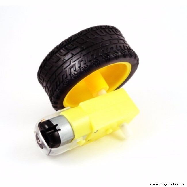
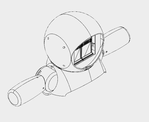
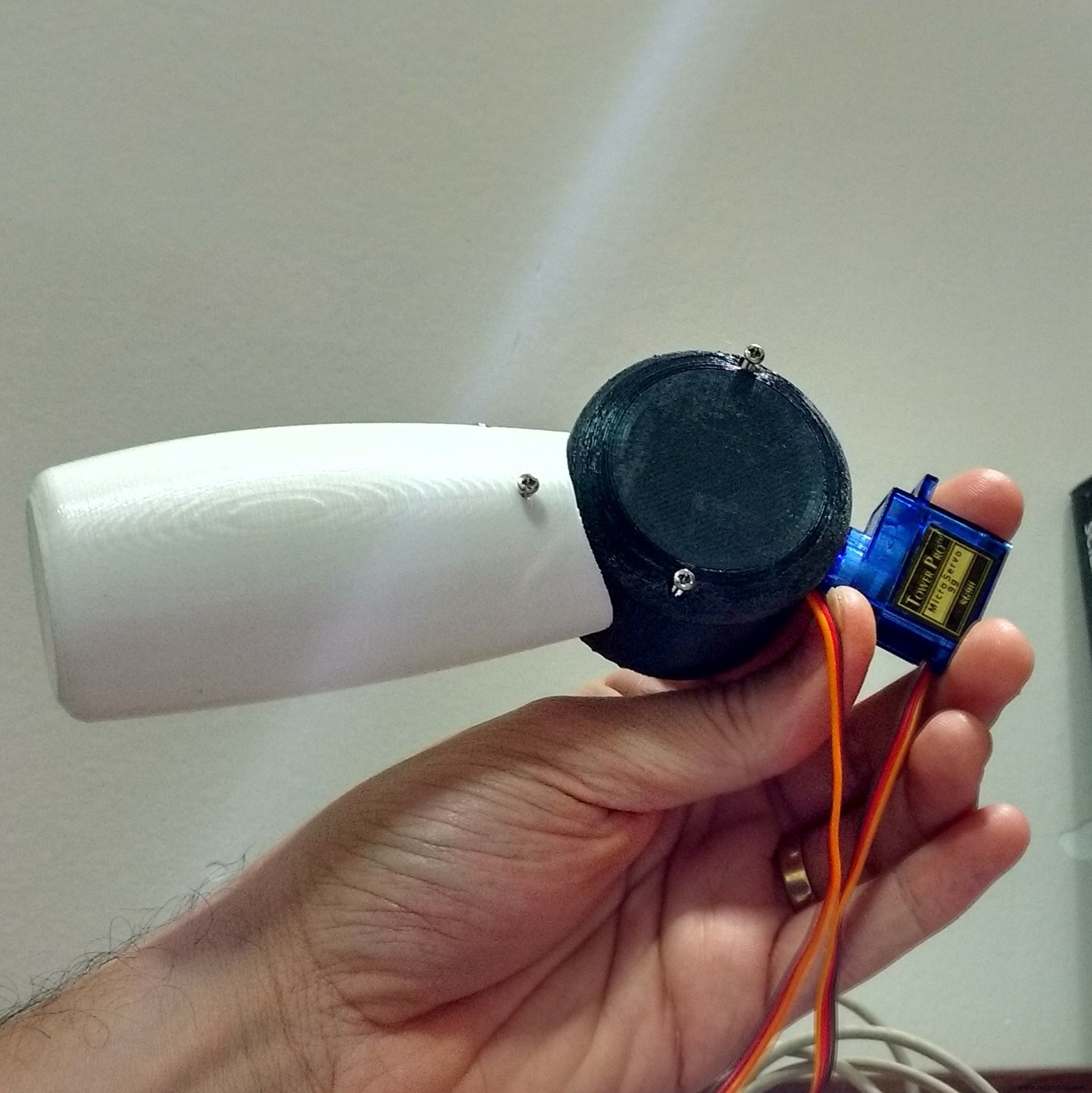
Step 10:Assembling the Wheels
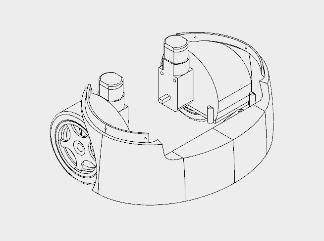
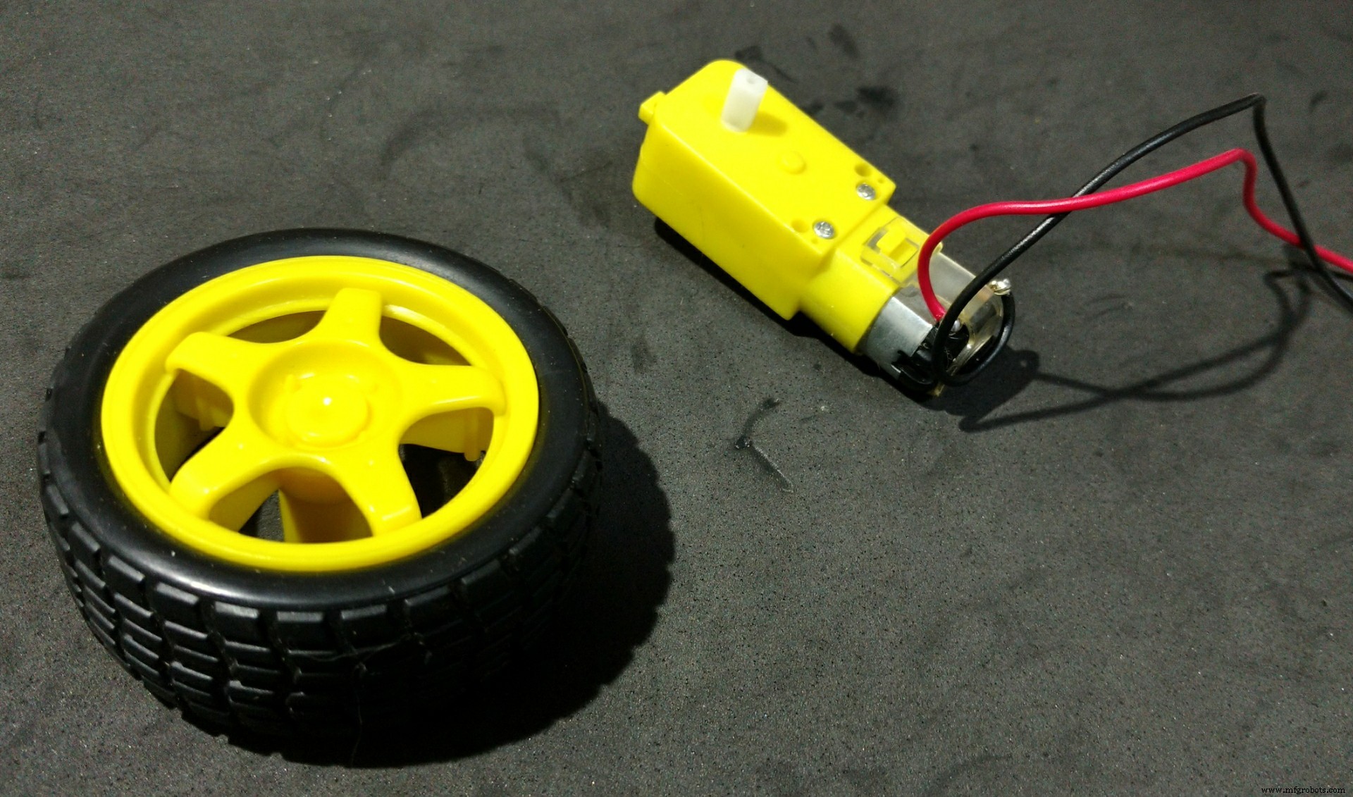
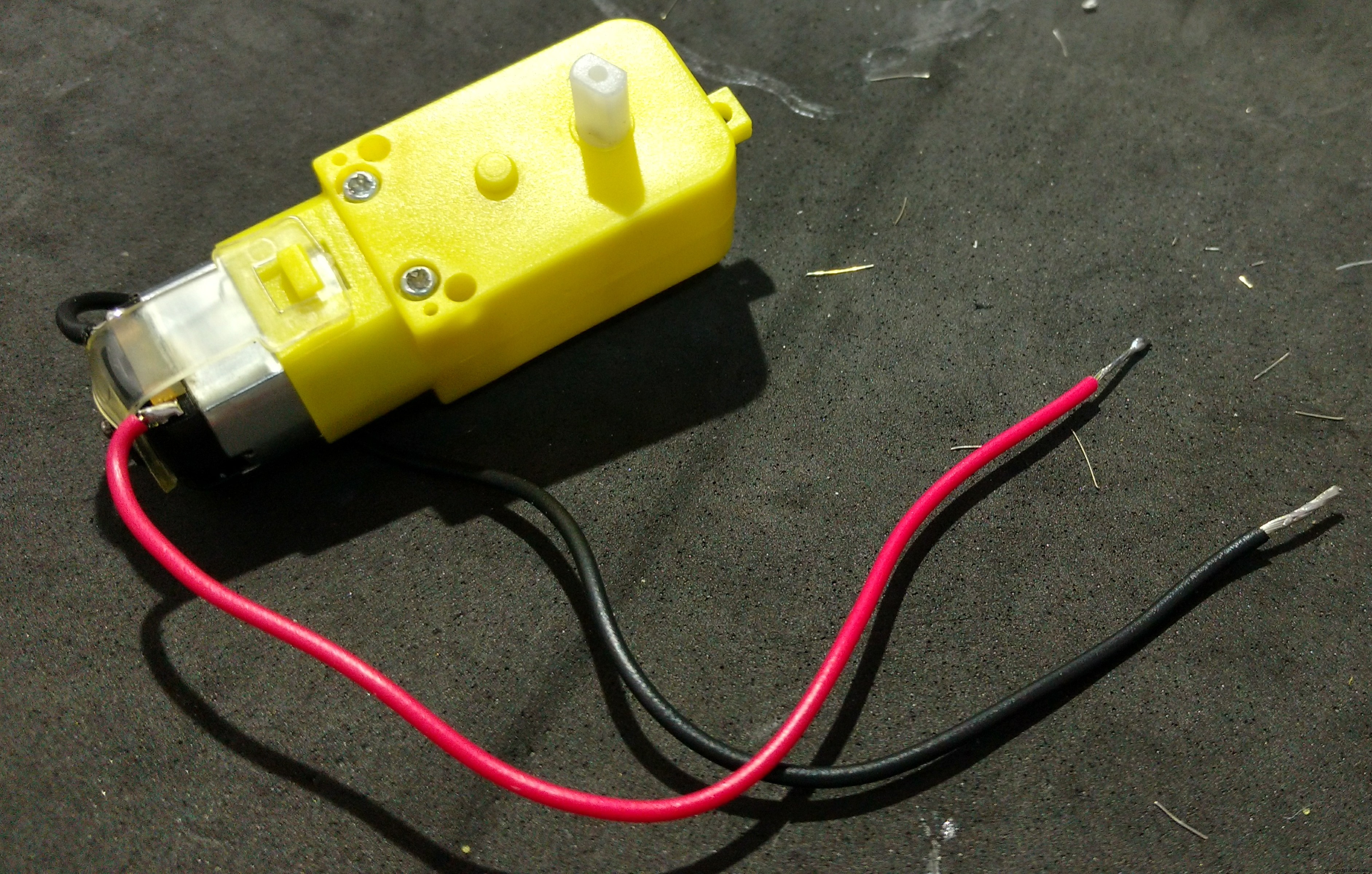
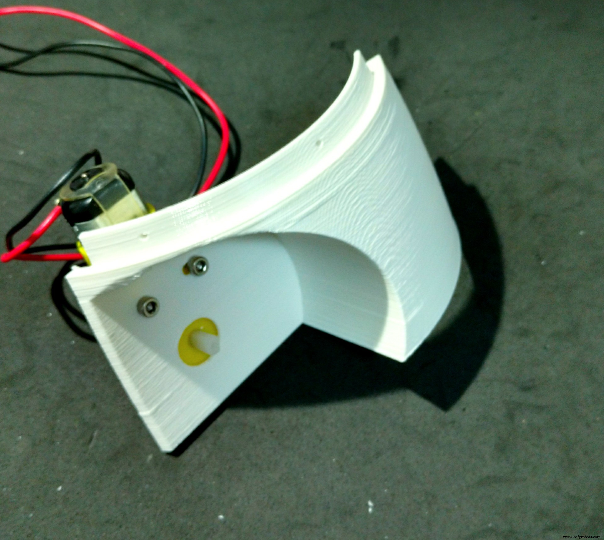

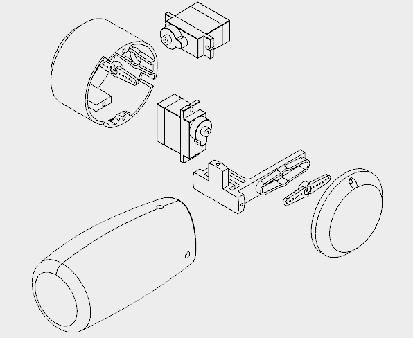
The wheels of the robot uses three 3d printed parts:
<울>It took me around 10h to print those parts.
I followed the following steps for assembling the wheels:
<울>
Step 11:Phone Holder
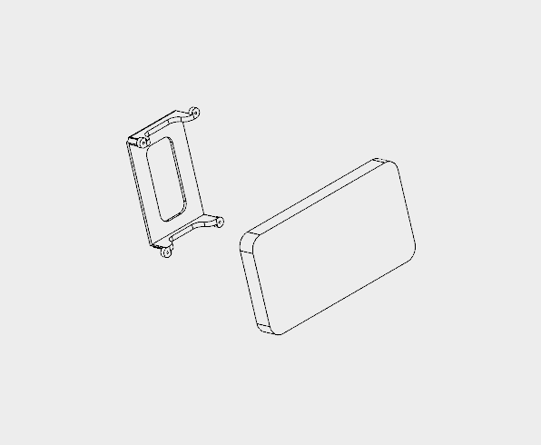

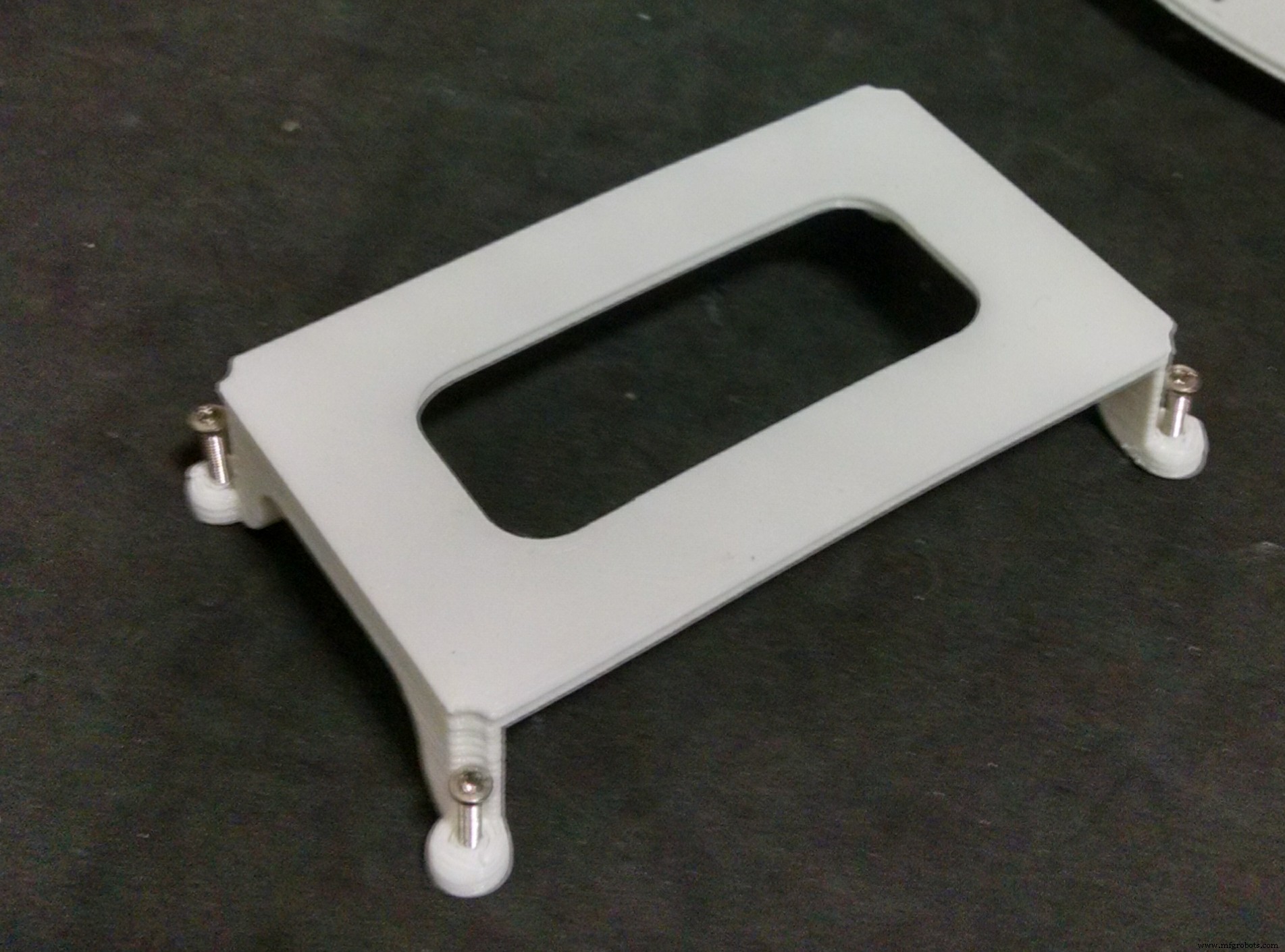
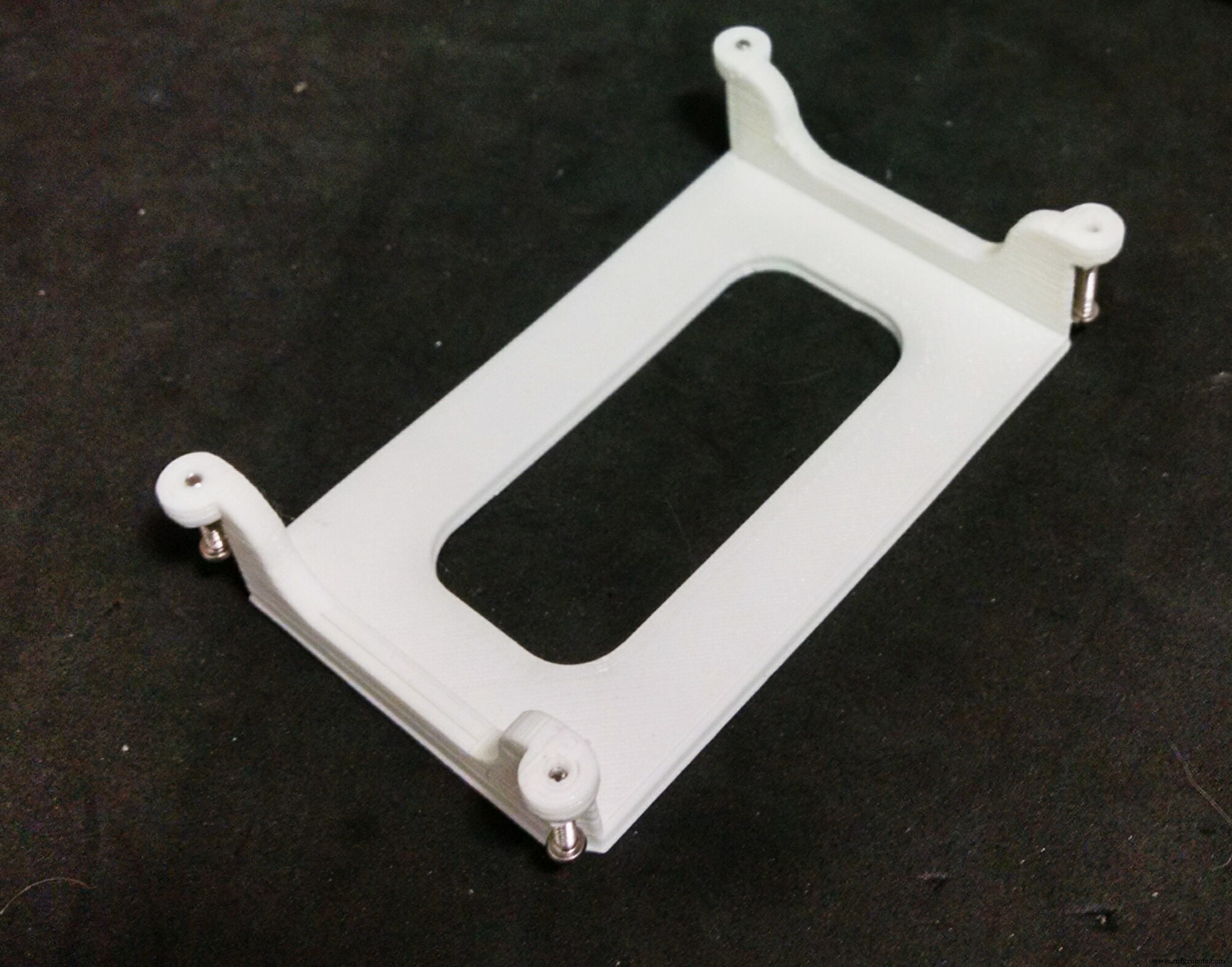
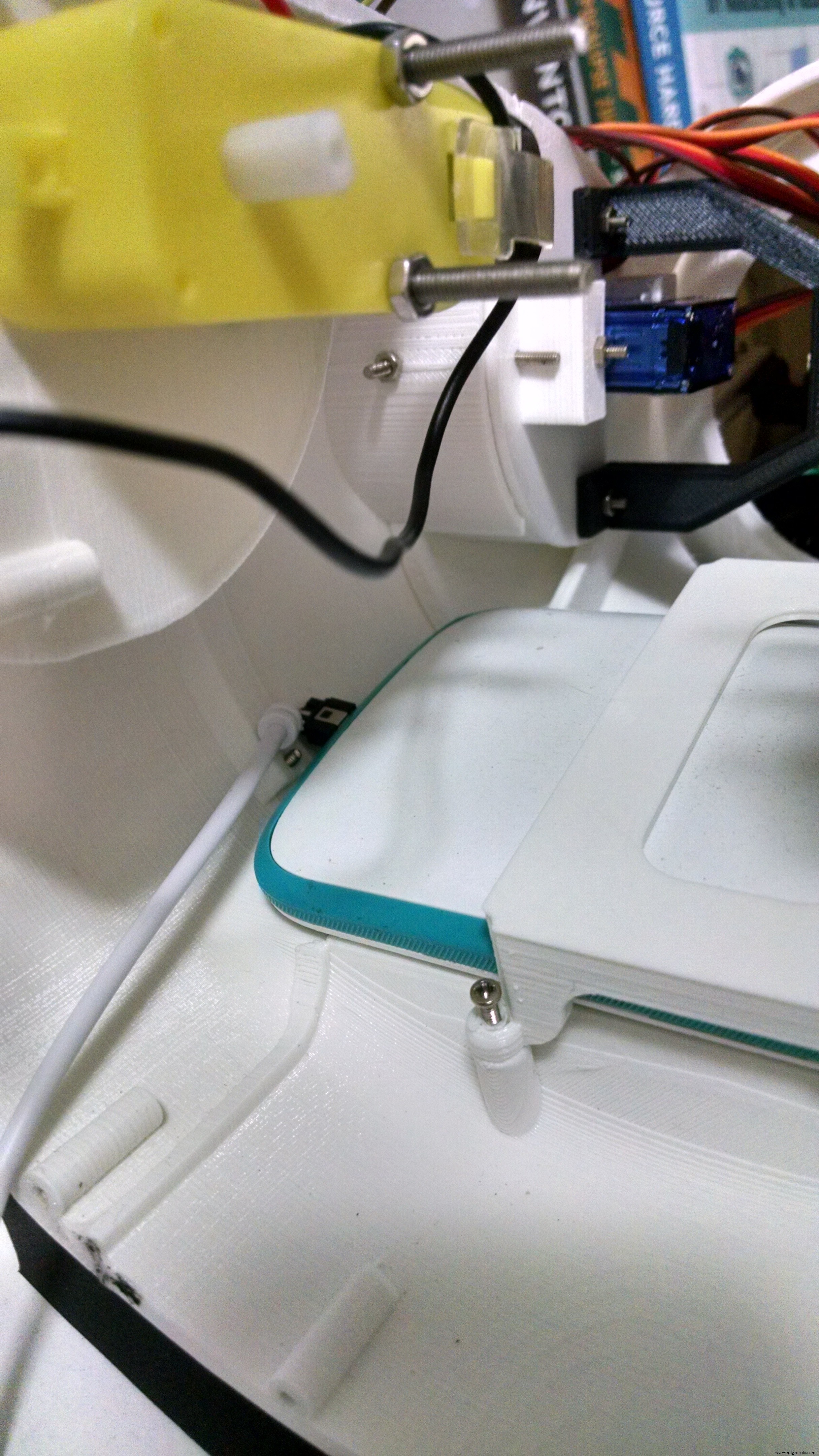
The phone holder is a single 3d printed part, and it takes around 1 hour to print.
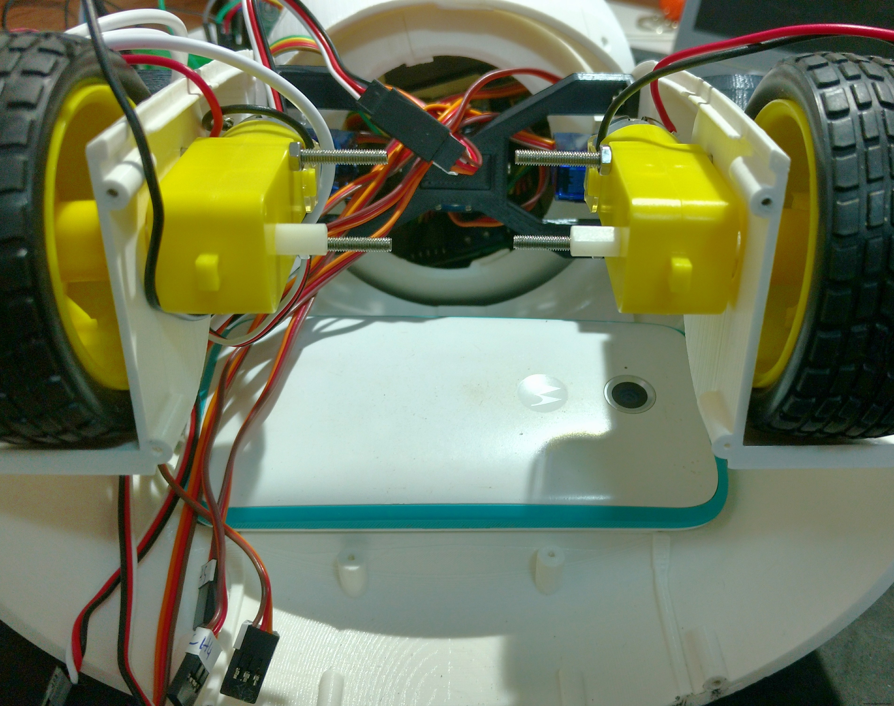
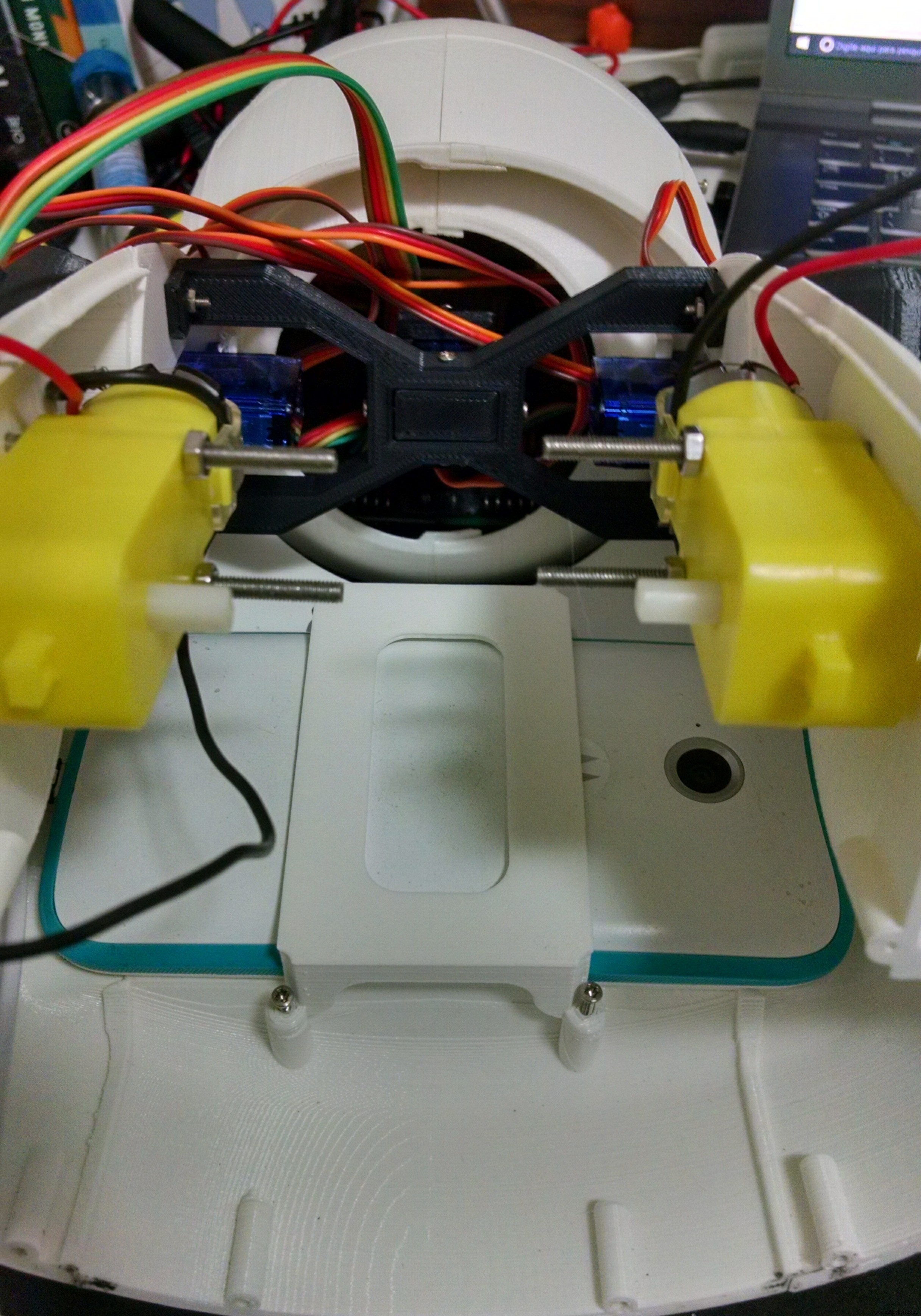
The robot has a smartphone at it's belly. It was designed for a Motorola Moto E. It has a 4.3" display. Other smartphones with similar size might fit as well.
The phone holder part is used to hold the smartphone in the desired position. First the smart phone is positioned, then it's pressed against the body of the robot using the phone holder and four M2x6mm bolts.
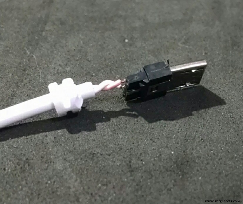
It's importart to connect the USB cabe to the smartphone before tightening the bolts. Otherwise it will be hard to connect it later. Unfortunatly the space is very limited, so I had to cut part of the USB connector away... :/
Step 12:Mounting the Base
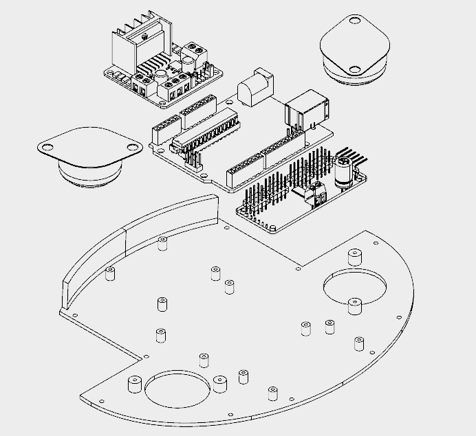
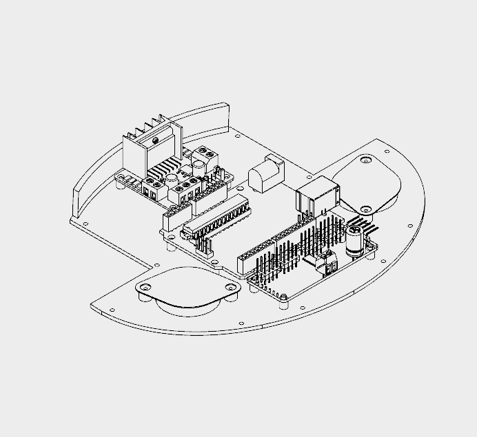
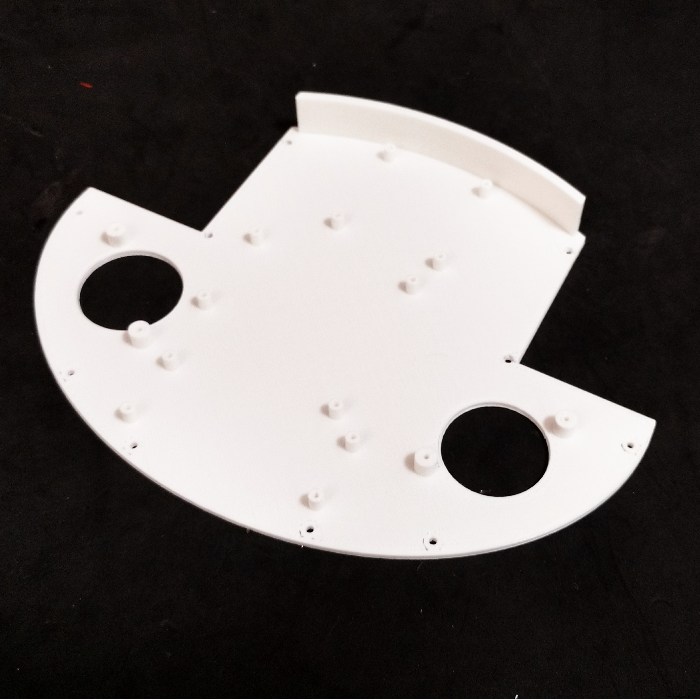
The base has only one 3D printed part. It took me around 4h to print that part.
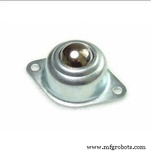
It has several holes for the installation of other components, like the ball wheels, and circuit boards for instance. The following procedure was used for assembling the base:
<울>
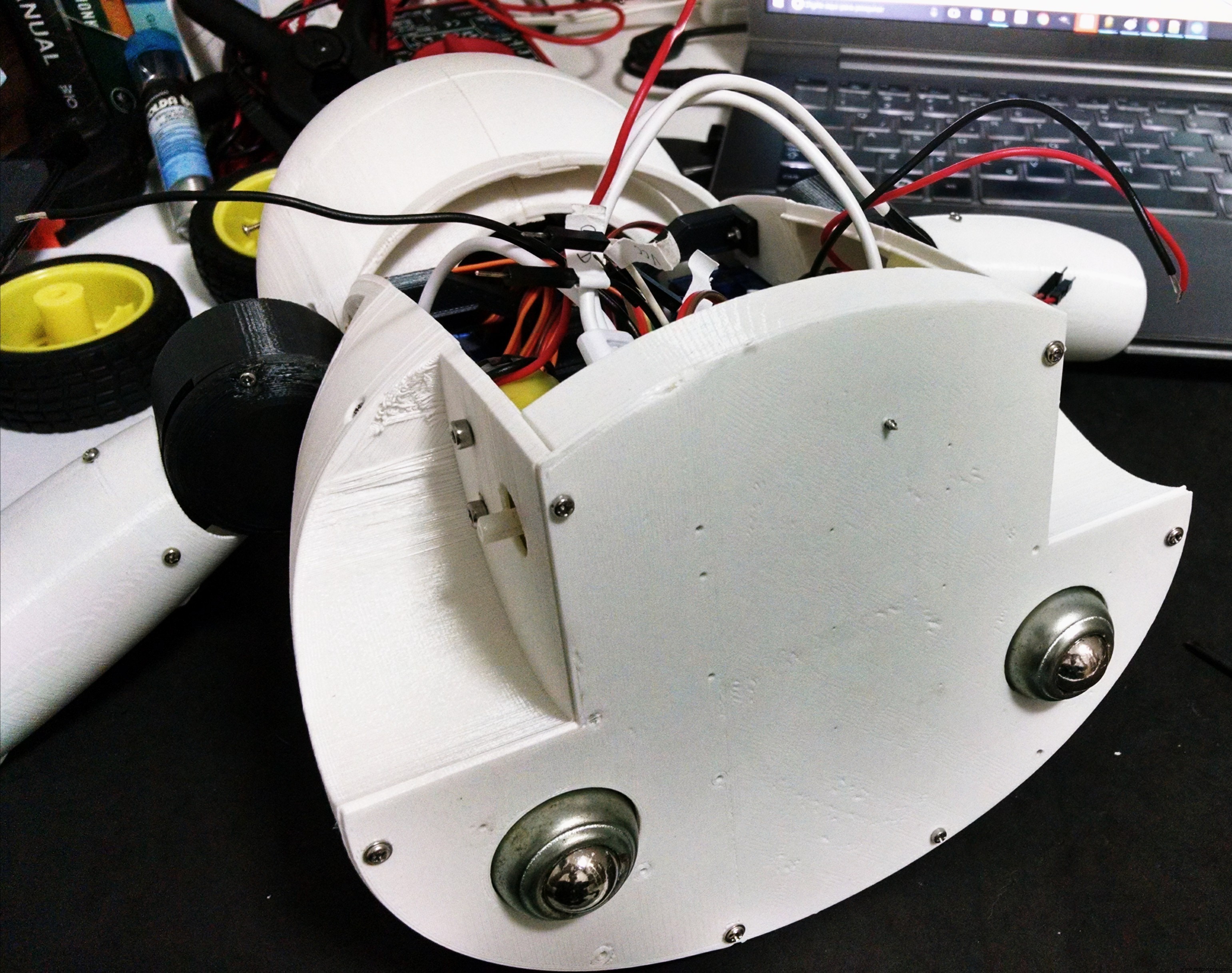
Step 13:Back and Power Pack
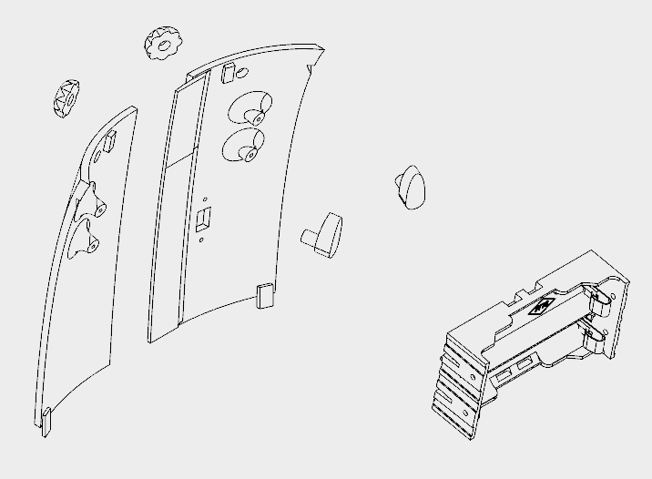


The back cover of the robot was designed so that one can easilly open it for accessing the circuits, recharging the batteries, or turning the smartphone on/off.
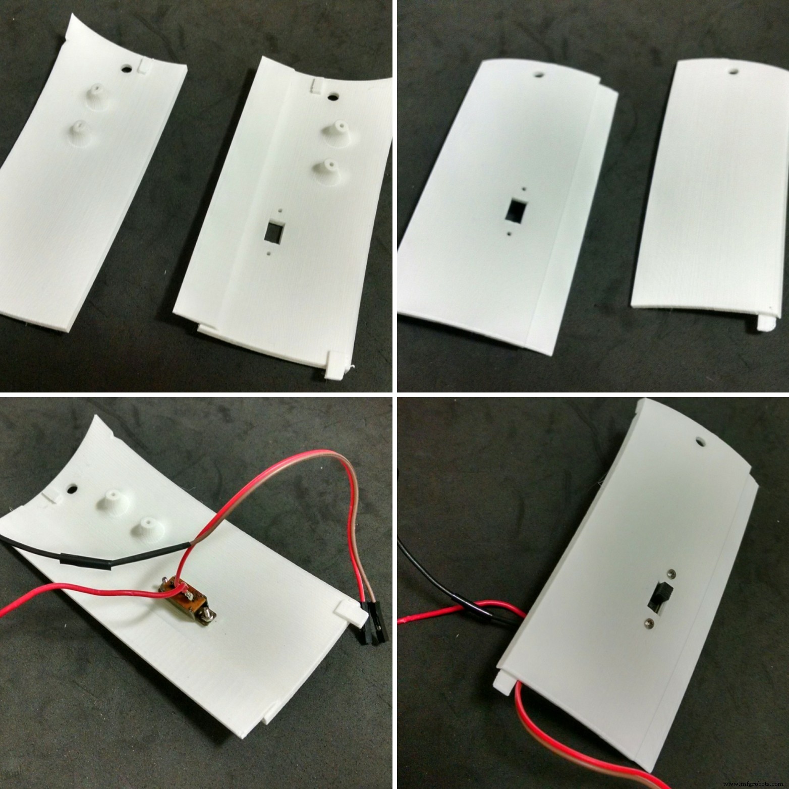
It's made of six 3d printed parts:
<울>It took me around 5h30 for printing the parts. Right and left back parts were glued using superglue. Wait until the glue is completly dry, or the cover will break easilly.
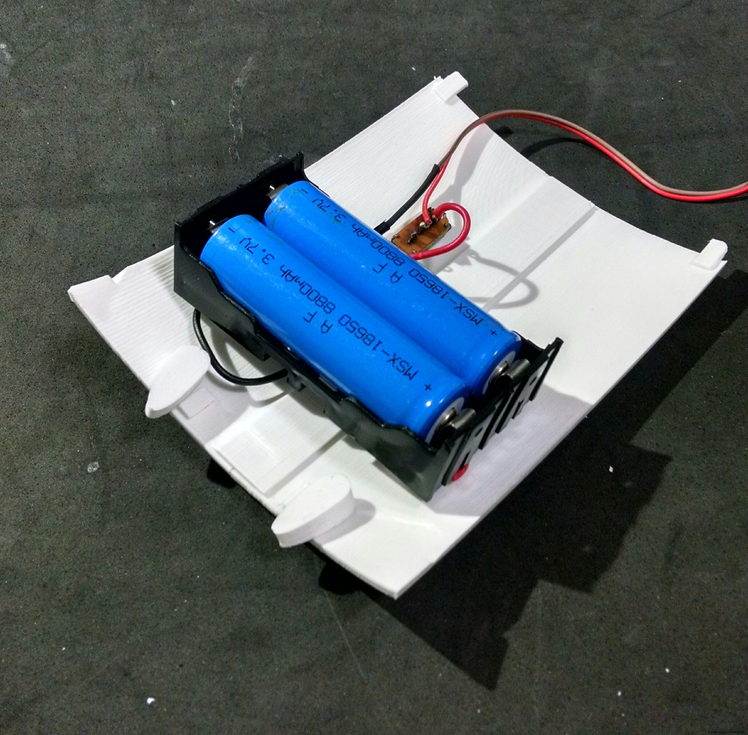
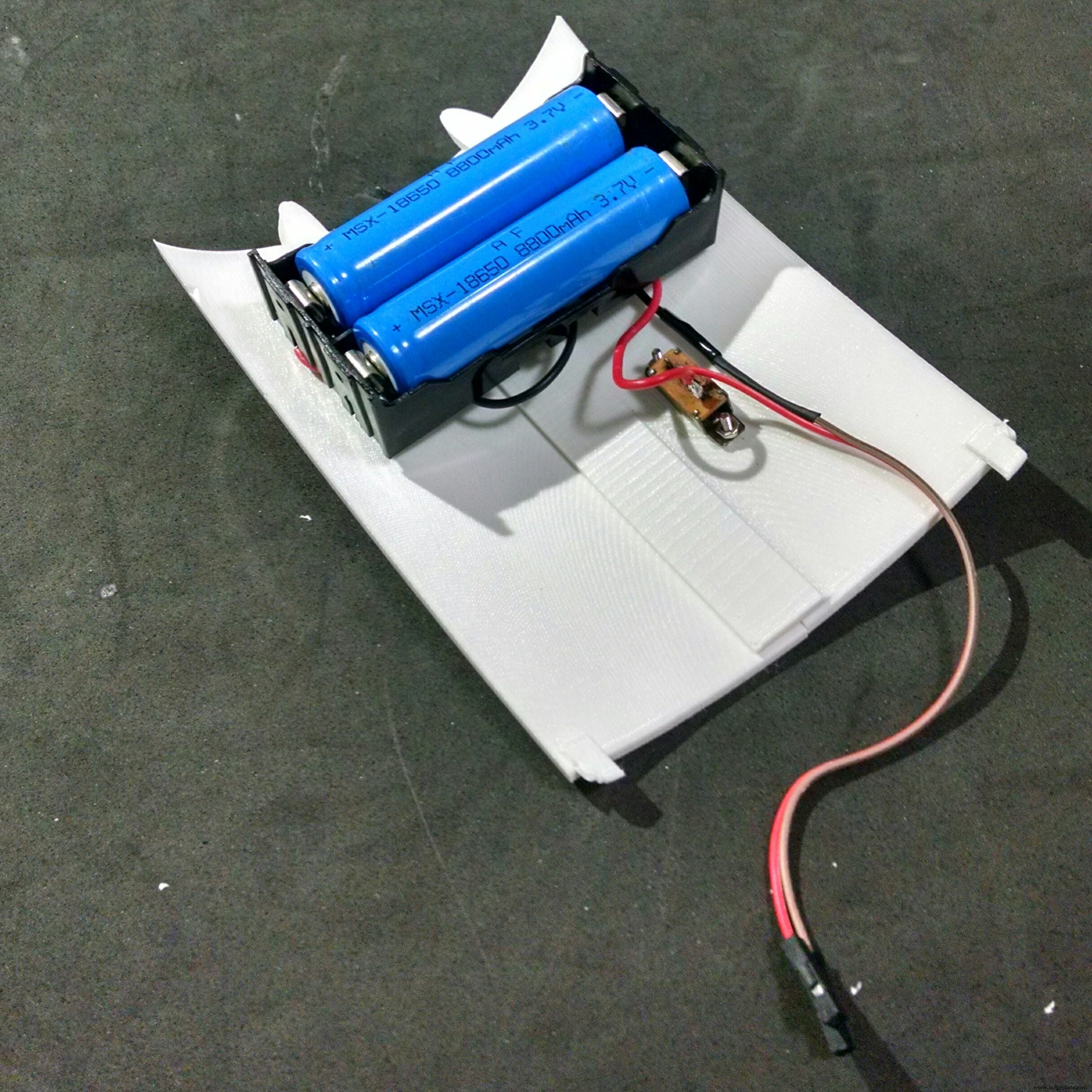
The power pack consists of two 18650 batteries and a battery holder. I had to solder some wires (between battery #1 negative pole and battery #2 positive pole). The negative pole of the power pack was connected to Arduinos GND (using some wires and jumpers). A on/off swich was installed between the positive pole and Arduino's Vin input.
The on/off switch was attached to back 3d printed parts using a M2x6mm bolt and M2x1.5mm nut. The battery holder was attached to the back using four M2x6mm bolts.
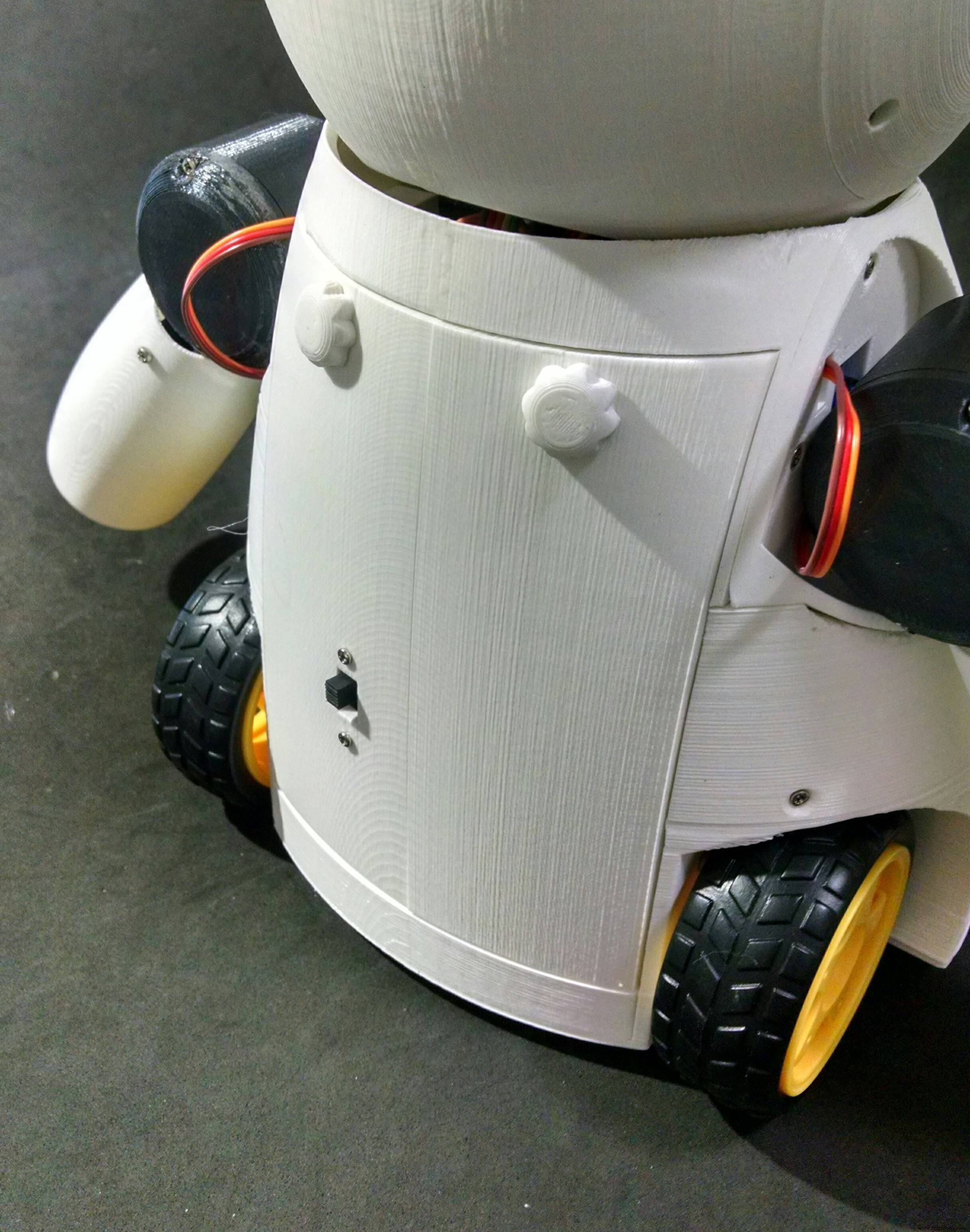
The cilindrical part of the locks had to be sanded with a sand paper for a better fitting. They pass through the holes on the cover. The knobs are connected and glued on the other side.
The cover fits to the back of the robot. The knobs can be turned for locking the lid, protecting the insides of the robot.
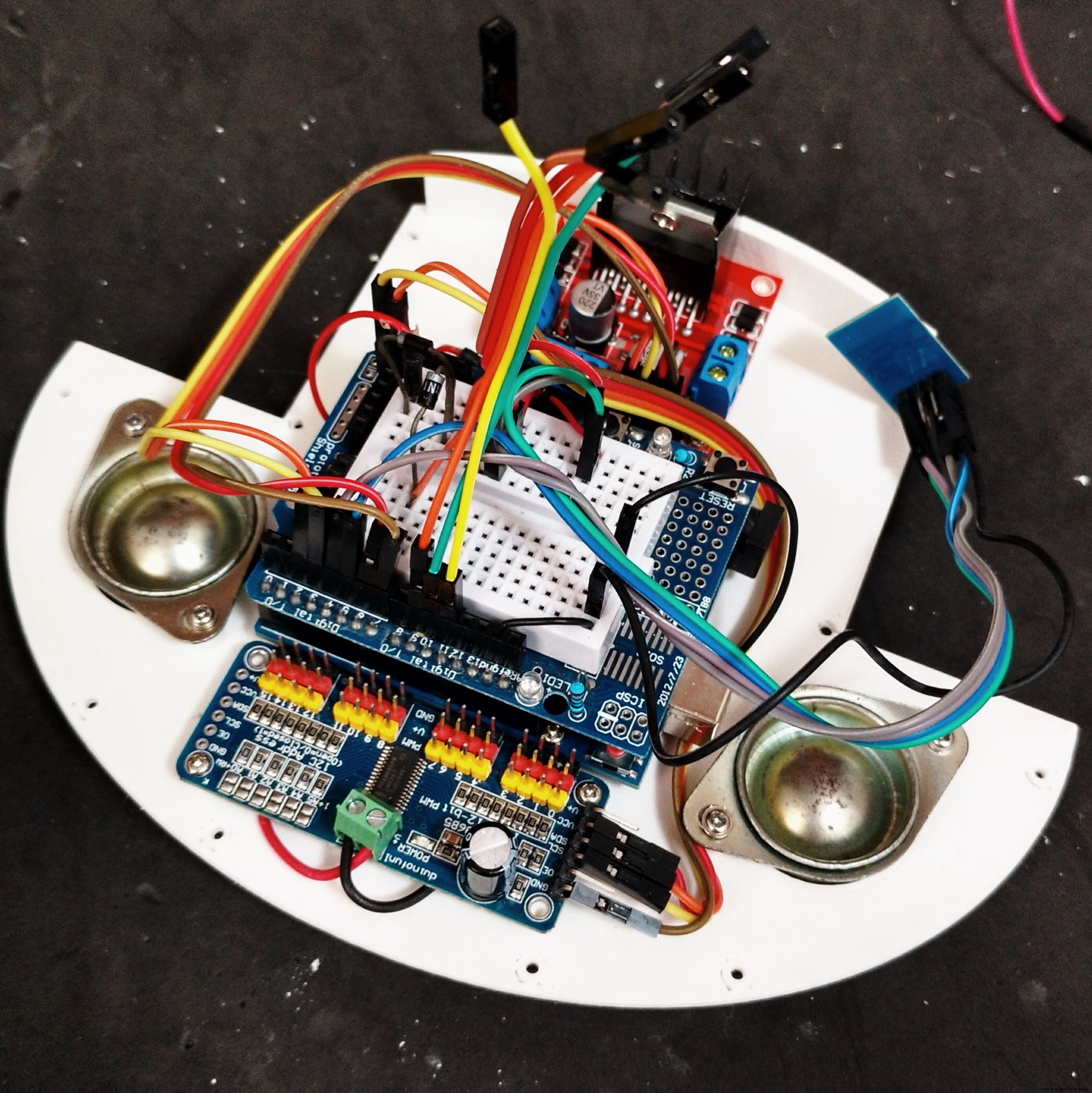
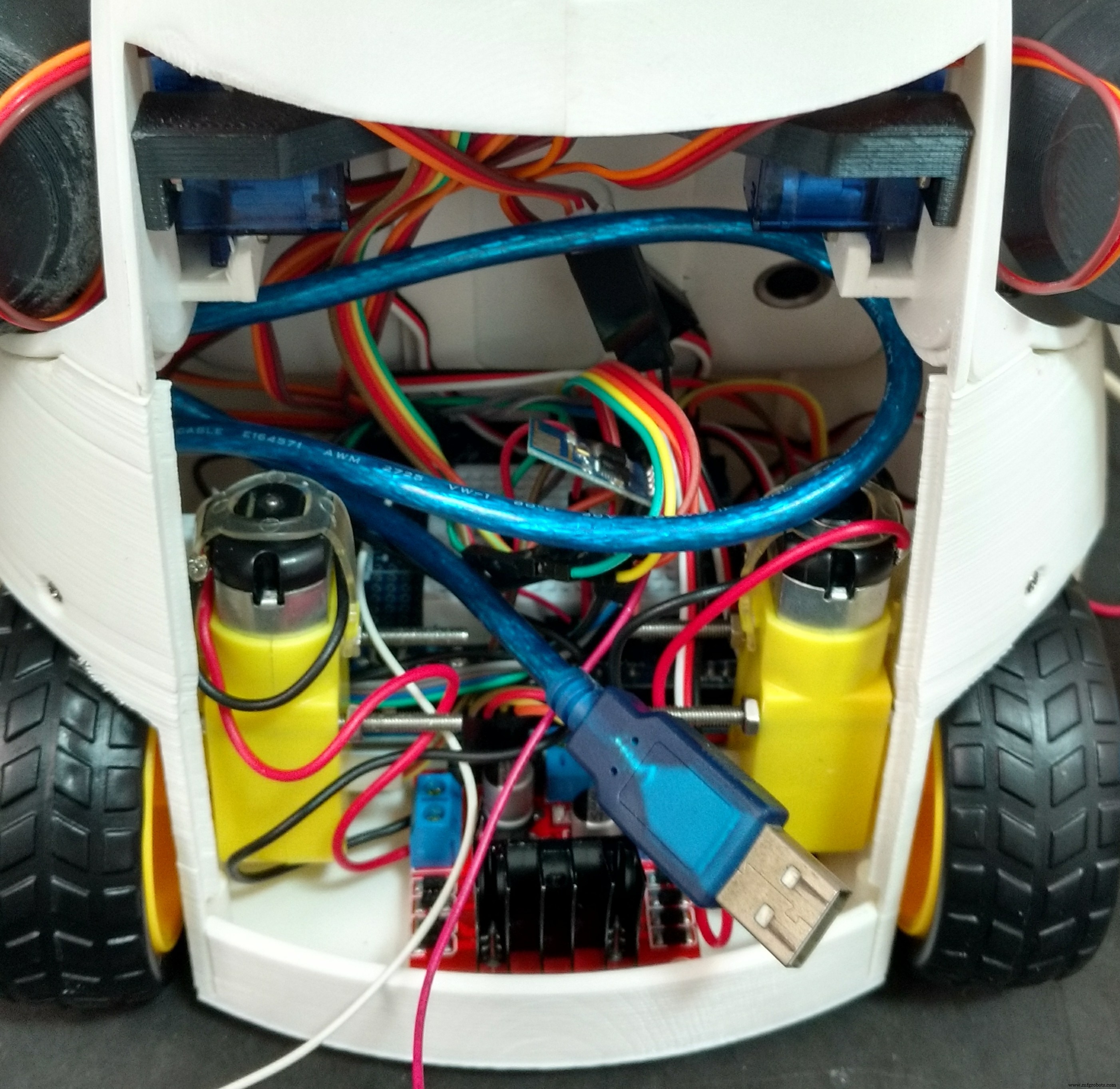
Step 14:Wiring Up the Circuits

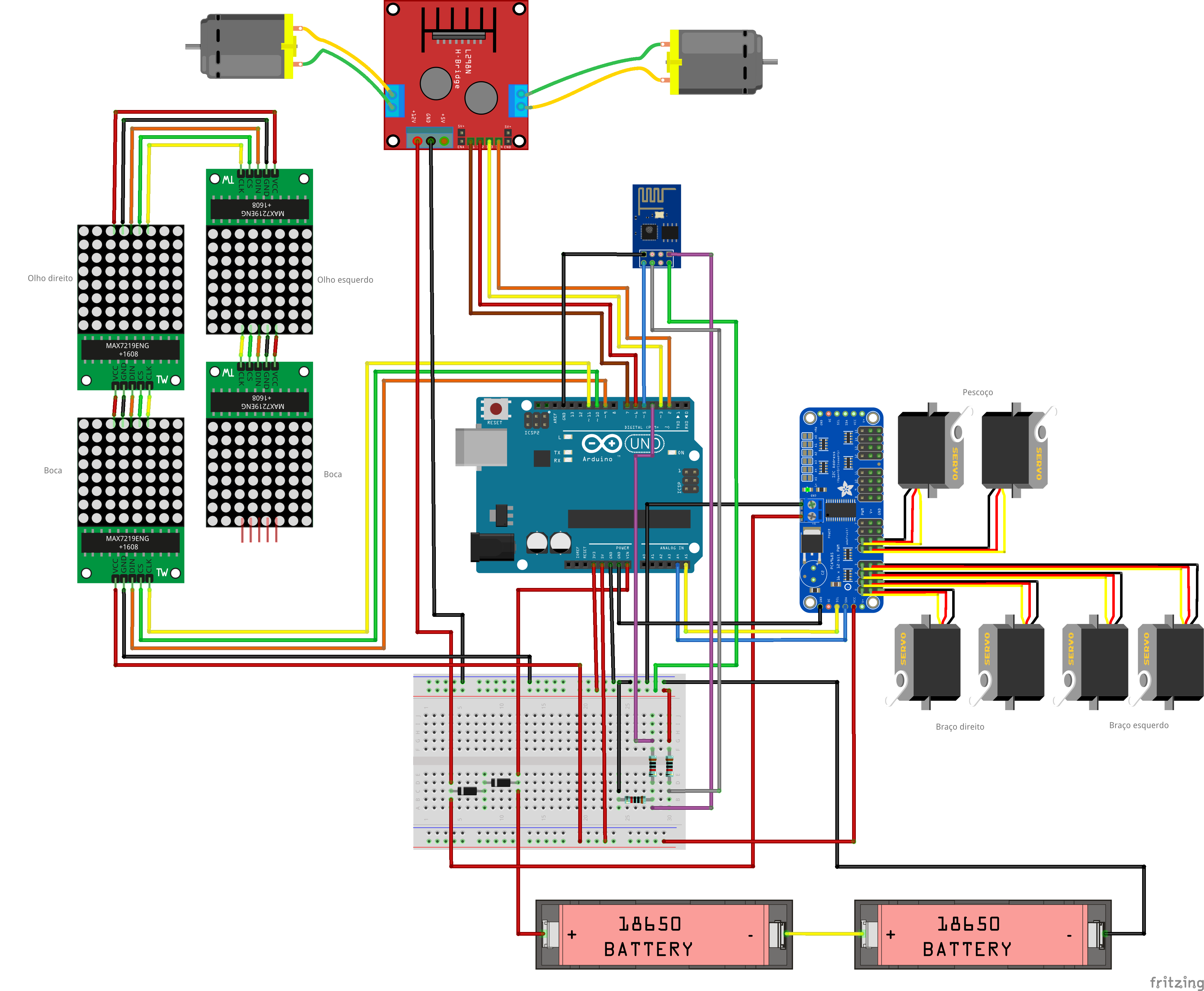
The circuit was wired up according to the schematics.
Arduino:
<울>ESP8266-01
<울>L298N h-bridge
<울>MAX7219 (first matrix)
<울>MAX7219 (other matrixes)
<울>16-channel servo controller
<울>Some say the Sg90 servo can be powered between 3.0 and 6.0V, others between 4.0 and 7.2V. To avoid trouble I decided to put two diodes in series after the batteries. This way, the voltage for servos is 2*3.7 - 2*0.7 =6.0V. The same is applied to the DC motors.
Notice this is not the most efficient way, but it worked for me.
robot%2Bmk0%2B-%2Brev8_bb.pdf robot%2Bmk0%2B-%2Brev8_Esquem_C3_A1tico.pdf
Step 15:Arduino Code
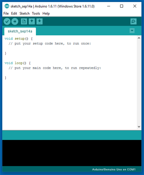

Install the latest Arduino IDE. No library was needed for communication with ESP-8266 module or control of the DC motors.
I'll need to add the following libraries:
<울>Arduino code is divided in 9 parts:
<울>Download Arduino code. Replace the XXXXX by your wifi router SSID and YYYYY by router password on on '_80_Setup.ino'. Please check the baudrate of you ESP8266 and set it properly in the code ('_80_Setup.ino'). Connect the Arduino board to your computer USB port and upload the code.
RoboAlegria.rar
Step 16:Android Apps
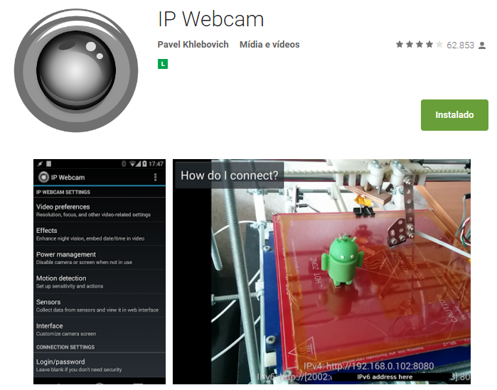
An Android smartphone was used to broadcast the video and audio from the robot to the control interface. You can find the app I used on Google Play store (https://play.google.com/store/apps/details?id=com.pas.webcam).
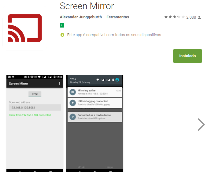
The screen of the smartphone may also be transmited to the control interface, so that the operator can see what's on the screen. You can also find the app I used to mirror the screnn on Google Play store (https://play.google.com/store/apps/details?id=com.ajungg.screenmirror).
An Android video game was also designed to interact with the robot. It's not yet very stable, so it isn't available for download.
Step 17:Control Interface
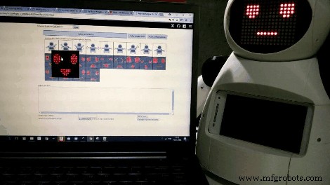


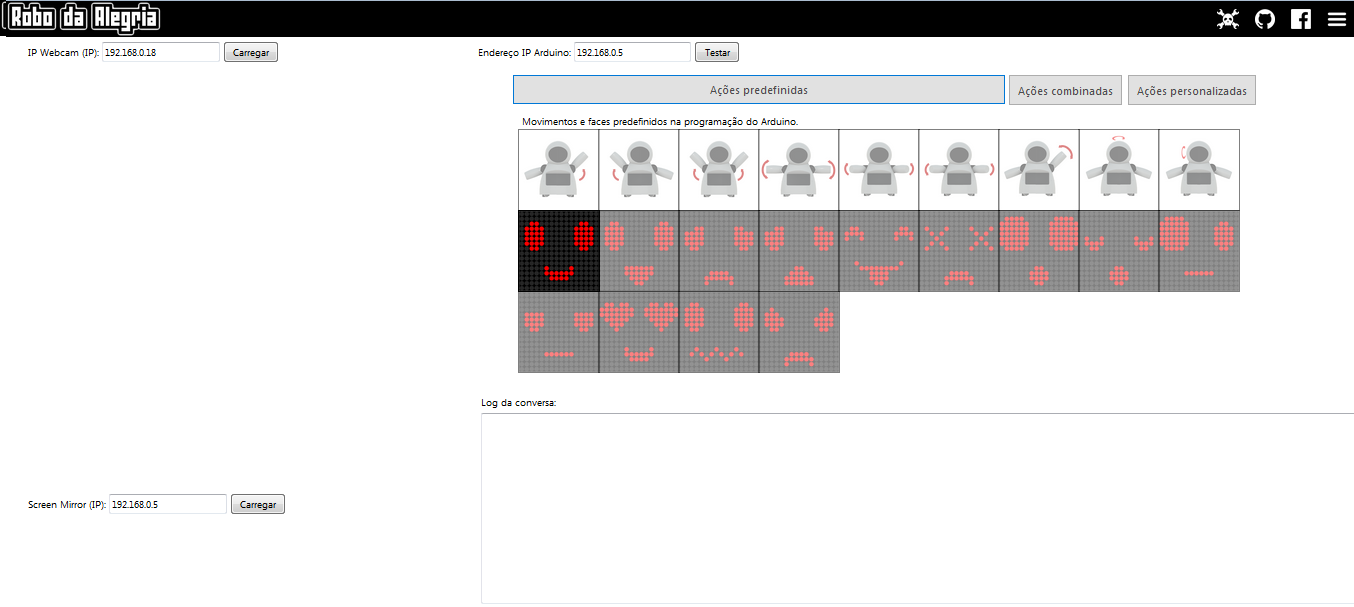
A html interface was designed for the control of the robot.Download interface.rar and extract all the files to a given folder. Then open it on Firefox. The interface is divided in two blocks. To the left there are displays for the camera and screen mirror. To the right there are controll buttons for the commands.
Textbox forms are used in that interface to enter IP address of the ESP8266 module ('Endereço IP Arduino:'), video/audio server from Android IP Webcam app ('IP Webcam (IP):') and Screen Mirror IP address ('Screen Mirror (IP):').
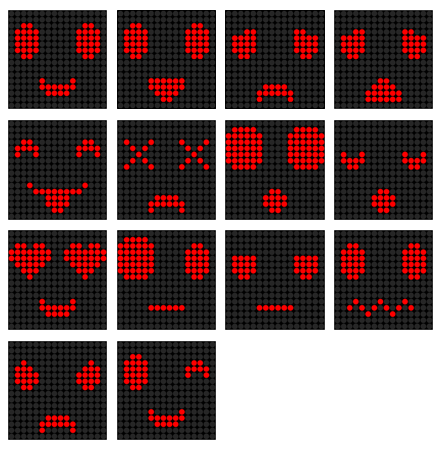
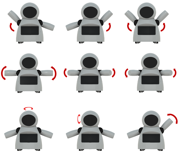
Under 'Ações predefinidas' tab user can select between 9 predefined body movements and 13 different faces. On 'Ações personalizadas' tab user can set a given angles for each of the 6 servos, and individually select between 9 eyes possibilities and 8 mouths variations. A javascript function runs whenever one of those buttons is clicked, and a message is sent for ESP8266's IP address.
Keyboard arrow keys are used for moving the robot forward or backward, and to rotate left or right.
When the interface is started, a warning is displayed, asking if the user wants to share the microphone. If this option is selected, sound intensity of the microphone will be used to send a preconfigured command to the robot. This command will trigger an animation, simulating speech movement on robot's face. A settings button on upper right corner might be used to set the sensitivity of the microphone.
This settings menu might also be used to configure the speed of arms and neck movements.
interface.rar
Step 18:Have Fun
Power it up and have fun!
If you like it, please share this tutorial with you friends! And don't forget to vote on Instructubles Contests! :D
http://www.instructables.com/id/Joy-Robot-Rob%C3%B4-Da-Alegria-Open-Source-3D-Printed-A/
<섹션 클래스="섹션 컨테이너 섹션 축소 가능" id="코드">미리보기 없음(다운로드만 가능).
미리보기 없음(다운로드만 가능).
제조공정
구성품 및 소모품 Arduino UNO × 1 Arduino용 PHPoC WiFi 실드 × 1 6DOF 암 로봇 × 1 이 프로젝트 정보 초보자인 경우 다음 자습서를 읽는 것이 좋습니다. Arduino - 모터 Arduino - 서보 모터 아두이노 - 와이파이 1. 시연 2. 사용자 인터페이스 로봇 팔에는 6개의 모터가 있습니다. 영역 A:모터 2, 3, 4 제어(손 관절 3개 제어) 영역 B:제어 모터 1(제어 베이스) 영역
구성품 및 소모품 Arduino UNO × 1 Adafruit L293D 모터 실드 저가 장치이며 사용하기 쉽습니다. 이전 기술이 필요하지 않은 일반적으로 사용 가능한 모터 실드입니다. Adafruit 라이브러리를 사용하여 쉽게 프로그래밍할 수도 있습니다. × 1 HC-SR4 초음파 센서 × 1 HC-05 블루투스 모듈 × 1 기어드 모터 × 2 휠 × 2 캐스터 휠 × 2 9V 배터리(일반)