

verilog

산업 제조
generate 블록을 사용하면 모듈 인스턴스를 곱하거나 모든 모듈의 조건부 인스턴스화를 수행할 수 있습니다. Verilog 매개변수를 기반으로 설계할 수 있는 기능을 제공합니다. 이러한 명령문은 동일한 작업 또는 모듈 인스턴스를 여러 번 반복해야 하거나 주어진 Verilog 매개변수를 기반으로 특정 코드를 조건부로 포함해야 하는 경우에 특히 편리합니다.
generate 블록은 포트, 매개변수, specparam를 포함할 수 없습니다. 선언 또는 specify 블록. 그러나 다른 모듈 항목 및 기타 생성 블록은 허용됩니다. 모든 생성 인스턴스는 module 내에 코딩됩니다. 키워드 generate 사이 및 endgenerate .
생성된 인스턴스화는 모듈, 연속 할당, always 중 하나를 가질 수 있습니다. 또는 initial 블록 및 사용자 정의 프리미티브. 생성 구문에는 루프와 조건의 두 가지 유형이 있습니다.
반가산기는 generate을 사용하여 my_design이라는 다른 최상위 디자인 모듈에서 N번 인스턴스화됩니다. for 루프 구성. 루프 변수는 genvar 키워드를 사용하여 선언해야 합니다. 이는 이 변수가 생성 블록을 정교화하는 동안 특별히 사용된다는 것을 도구에 알려줍니다.
// Design for a half-adder
module ha ( input   a, b,
            output  sum, cout);

  assign sum  = a ^ b;
  assign cout = a & b;
endmodule

// A top level design that contains N instances of half adder
module my_design
	#(parameter N=4)
		(	input [N-1:0] a, b,
			output [N-1:0] sum, cout);

	// Declare a temporary loop variable to be used during
	// generation and won't be available during simulation
	genvar i;

	// Generate for loop to instantiate N times
	generate
		for (i = 0; i < N; i = i + 1) begin
          ha u0 (a[i], b[i], sum[i], cout[i]);
		end
	endgenerate
endmodule
testbench 매개변수는 설계에서 반가산기 인스턴스의 수를 제어하는 데 사용됩니다. N이 2일 때 my_design은 2개의 반가산기 인스턴스를 갖게 됩니다.
module tb;
	parameter N = 2;
  reg  [N-1:0] a, b;
  wire [N-1:0] sum, cout;

  // Instantiate top level design with N=2 so that it will have 2
  // separate instances of half adders and both are given two separate
  // inputs
  my_design #(.N(N)) md( .a(a), .b(b), .sum(sum), .cout(cout));

  initial begin
    a <= 0;
    b <= 0;

    $monitor ("a=0x%0h b=0x%0h sum=0x%0h cout=0x%0h", a, b, sum, cout);

    #10 a <= 'h2;
    		b <= 'h3;
    #20 b <= 'h4;
    #10 a <= 'h5;
  end
endmodule
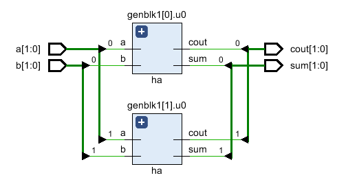
a[0] 및 b[0]은 출력 sum[0] 및 cout[0]을 제공하고 a[1] 및 b[1]은 출력 sum[1] 및 cout[1]을 제공합니다.
시뮬레이션 로그ncsim> run a=0x0 b=0x0 sum=0x0 cout=0x0 a=0x2 b=0x3 sum=0x1 cout=0x2 a=0x2 b=0x0 sum=0x2 cout=0x0 a=0x1 b=0x0 sum=0x1 cout=0x0 ncsim: *W,RNQUIE: Simulation is complete. ncsim> exit
정교한 RTL에는 실제로 generate에 의해 생성된 두 개의 반가산기 인스턴스가 있습니다. 차단합니다.
아래는 if else를 사용한 예입니다. generate 내부 두 개의 서로 다른 멀티플렉서 구현 중에서 선택하는 구성입니다. 첫 번째 디자인은 assign을 사용합니다. 두 번째 디자인이 case을 사용하는 동안 mux를 구현하는 문 성명. USE_CASE라는 매개변수는 두 가지 선택 중 하나를 선택하기 위해 최상위 디자인 모듈에 정의되어 있습니다.
// Design #1: Multiplexer design uses an "assign" statement to assign
// out signal
module mux_assign ( input a, b, sel,
                   output out);
  assign out = sel ? a : b;

  // The initial display statement is used so that
  // we know which design got instantiated from simulation
  // logs
  initial
  	$display ("mux_assign is instantiated");
endmodule

// Design #2: Multiplexer design uses a "case" statement to drive
// out signal
module mux_case (input a, b, sel,
                 output reg out);
  always @ (a or b or sel) begin
  	case (sel)
    	0 : out = a;
   	 	1 : out = b;
  	endcase
  end

  // The initial display statement is used so that
  // we know which design got instantiated from simulation
  // logs
  initial
    $display ("mux_case is instantiated");
endmodule

// Top Level Design: Use a parameter to choose either one
module my_design (	input a, b, sel,
         			output out);
  parameter USE_CASE = 0;

  // Use a "generate" block to instantiate either mux_case
  // or mux_assign using an if else construct with generate
  generate
  	if (USE_CASE)
      mux_case mc (.a(a), .b(b), .sel(sel), .out(out));
    else
      mux_assign ma (.a(a), .b(b), .sel(sel), .out(out));
  endgenerate

endmodule
Testbench는 최상위 모듈 my_design을 인스턴스화하고 매개변수 USE_CASE를 1로 설정하여 case을 사용하여 디자인을 인스턴스화합니다. 성명서.
module tb;
	// Declare testbench variables
  reg a, b, sel;
  wire out;
  integer i;

  // Instantiate top level design and set USE_CASE parameter to 1 so that
  // the design using case statement is instantiated
  my_design #(.USE_CASE(1)) u0 ( .a(a), .b(b), .sel(sel), .out(out));

  initial begin
  	// Initialize testbench variables
  	a <= 0;
    b <= 0;
    sel <= 0;

    // Assign random values to DUT inputs with some delay
    for (i = 0; i < 5; i = i + 1) begin
      #10 a <= $random;
      	  b <= $random;
          sel <= $random;
      $display ("i=%0d a=0x%0h b=0x%0h sel=0x%0h out=0x%0h", i, a, b, sel, out);
    end
  end
endmodule
매개변수 USE_CASE가 1일 때 case를 사용하여 멀티플렉서가 설계되었음을 시뮬레이션 로그에서 알 수 있습니다. 문이 인스턴스화됩니다. 그리고 USE_CASE가 0이면 assign을 사용하는 멀티플렉서 설계 문이 인스턴스화됩니다. 이것은 시뮬레이션 로그에 인쇄되는 표시 문에서 볼 수 있습니다.
// When USE_CASE = 1
ncsim> run
mux_case is instantiated
i=0 a=0x0 b=0x0 sel=0x0 out=0x0
i=1 a=0x0 b=0x1 sel=0x1 out=0x1
i=2 a=0x1 b=0x1 sel=0x1 out=0x1
i=3 a=0x1 b=0x0 sel=0x1 out=0x0
i=4 a=0x1 b=0x0 sel=0x1 out=0x0
ncsim: *W,RNQUIE: Simulation is complete.

// When USE_CASE = 0
ncsim> run
mux_assign is instantiated
i=0 a=0x0 b=0x0 sel=0x0 out=0x0
i=1 a=0x0 b=0x1 sel=0x1 out=0x0
i=2 a=0x1 b=0x1 sel=0x1 out=0x1
i=3 a=0x1 b=0x0 sel=0x1 out=0x1
i=4 a=0x1 b=0x0 sel=0x1 out=0x1
ncsim: *W,RNQUIE: Simulation is complete.
생성 사례를 사용하면 case을 기반으로 하는 모듈, initial 및 always 블록을 다른 모듈에서 인스턴스화할 수 있습니다. 많은 선택 중 하나를 선택하는 표현식입니다.
// Design #1: Half adder
module ha (input a, b,
           output reg sum, cout);
  always @ (a or b)
  {cout, sum} = a + b;

  initial
    $display ("Half adder instantiation");
endmodule

// Design #2: Full adder
module fa (input a, b, cin,
           output reg sum, cout);
  always @ (a or b or cin)
  {cout, sum} = a + b + cin;

    initial
      $display ("Full adder instantiation");
endmodule

// Top level design: Choose between half adder and full adder
module my_adder (input a, b, cin,
                 output sum, cout);
  parameter ADDER_TYPE = 1;

  generate
    case(ADDER_TYPE)
      0 : ha u0 (.a(a), .b(b), .sum(sum), .cout(cout));
      1 : fa u1 (.a(a), .b(b), .cin(cin), .sum(sum), .cout(cout));
    endcase
  endgenerate
endmodule
module tb;
  reg a, b, cin;
  wire sum, cout;

  my_adder #(.ADDER_TYPE(0)) u0 (.a(a), .b(b), .cin(cin), .sum(sum), .cout(cout));

  initial begin
    a <= 0;
    b <= 0;
    cin <= 0;

    $monitor("a=0x%0h b=0x%0h cin=0x%0h cout=0%0h sum=0x%0h",
             a, b, cin, cout, sum);

    for (int i = 0; i < 5; i = i + 1) begin
      #10 a <= $random;
      b <= $random;
      cin <= $random;
    end
  end
endmodule
반가산기가 인스턴스화되기 때문에 cin은 출력 sum 및 cout에 영향을 미치지 않습니다.
시뮬레이션 로그ncsim> run Half adder instantiation a=0x0 b=0x0 cin=0x0 cout=00 sum=0x0 a=0x0 b=0x1 cin=0x1 cout=00 sum=0x1 a=0x1 b=0x1 cin=0x1 cout=01 sum=0x0 a=0x1 b=0x0 cin=0x1 cout=00 sum=0x1 ncsim: *W,RNQUIE: Simulation is complete.
verilog
Verilog는 하드웨어 설명 언어이며 설계자가 RTL 설계를 시뮬레이션하여 논리 게이트로 변환할 필요가 없습니다. 시뮬레이션이 필요한 이유는 무엇입니까? 시뮬레이션은 RTL 코드가 의도한 대로 동작하는지 확인하기 위해 다른 시간에 다른 입력 자극을 설계에 적용하는 기술입니다. 기본적으로 시뮬레이션은 설계의 견고성을 검증하기 위해 잘 따라야 하는 기술입니다. 또한 가공된 칩이 실제 세계에서 사용되는 방식과 다양한 입력에 반응하는 방식과 유사합니다. 예를 들어, 위의 디자인은 출력 pe 보여진 바와 같이. 시뮬레이션을 통해
디자인 module pr_en ( input [7:0] a, input [7:0] b, input [7:0] c, input [7:0] d, input [1:0] sel, output reg [7:0] out); always @ (a or b or c or d or sel) begin if (sel == 2b00) out <= a; else if