


VHDL

산업 제조
Quartus IP 코어를 VUnit 검증 프레임워크로 VHDL 시뮬레이션에 포함시키고 싶었던 적이 있으신가요?
FPGA 엔지니어 Konstantinos Paraskevopoulos가 그런 생각을 했지만 적절한 튜토리얼을 찾지 못했습니다. 다행히 그는 재능으로 해결책을 찾아내 VHDLwhiz를 통해 이 게스트 기사로 공유했습니다.
Konstantinos에게 말씀을 넘깁니다!
VUnit으로 시스템 시뮬레이션 시 Quartus IP 카탈로그의 사전 정의된 IP를 설계에 포함시키는 것이 종종 바람직합니다. 이 튜토리얼은 외부 Quartus IP 라이브러리를 생성, 통합, VUnit 환경에 링크하는 데 필요한 지식을 제공합니다.
VUnit 입문? Getting started with VUnit 튜토리얼 확인
이 튜토리얼은 세 가지 주요 부분으로 구성됩니다:
기본 VHDL 지식과 ModelSim 기술 보유 가정.
시나리오로 Quartus 정수 연산 IP 리스트의 병렬 가산기(Parallel Adder) IP를 사용합니다.
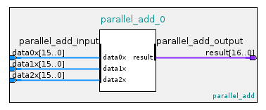
우리 설계는 세 개의 16비트 입력 벡터를 받아 17비트 출력 벡터로 더한 결과를 출력합니다.
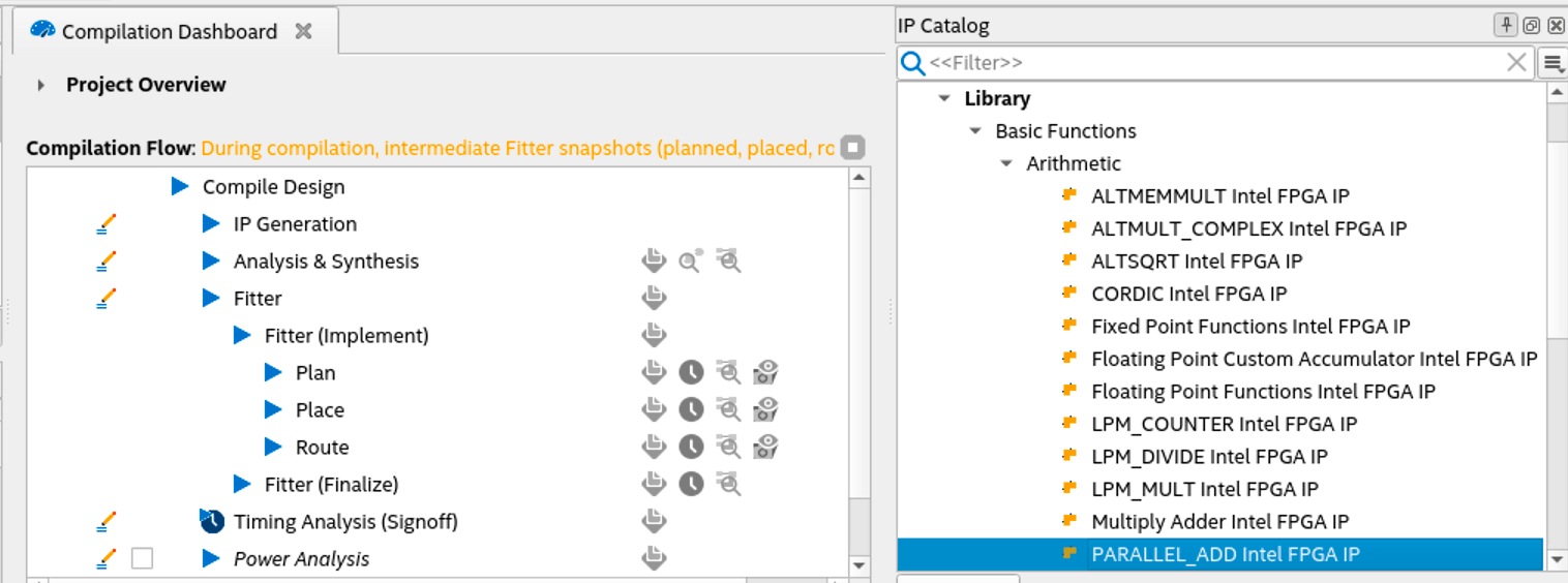
IP 카탈로그 창에서 Library/Basic functions/Arithmetic 아래 병렬 가산기 컴포넌트를 더블클릭해 가산기를 생성합니다.
이름 제공과 필요에 맞춘 커스터마이징 후 우하단 'Generate HDL' 버튼 클릭.
다음과 같은 창이 나타납니다.
주의: Simulation 섹션에서 Create simulation model을 VHDL 또는 Verilog로 설정해야 시뮬레이션 파일이 생성됩니다. 기본값은 none입니다. 선택하지 않으면 given_ip_name.spd 파일이 생성되지 않아 다음 단계가 실패합니다.
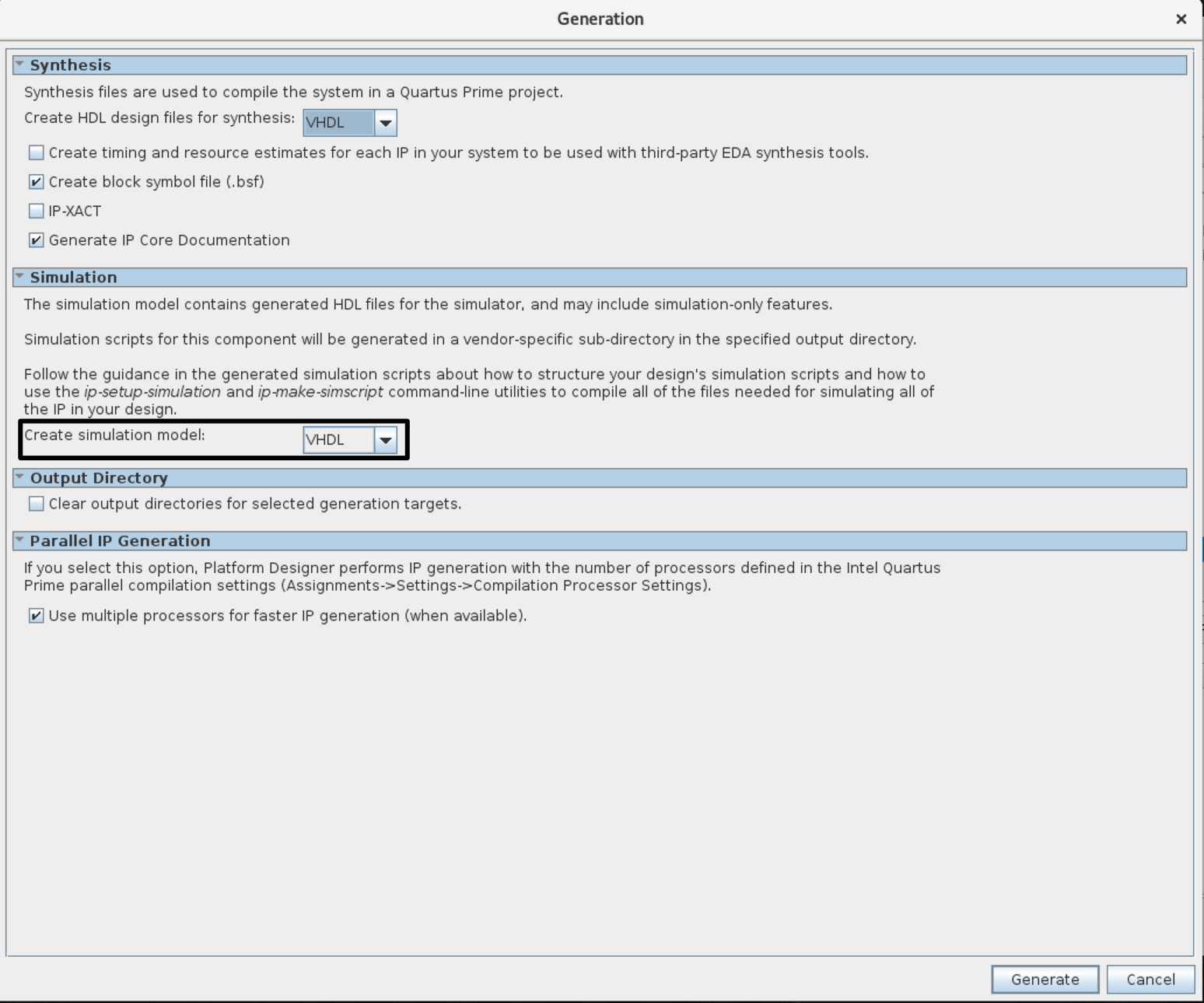
위 과정으로 quartus 디렉토리 하에 파일과 폴더 생성:
given_ip_name.ipgiven_ip_name (.vhd, .v 파일 포함, 나중에 run.py에 추가)ip-setup-simulation --quartus-project= <project's_QPF_filepath> \ --output-directory= <my_dir>위 두 방법 중 하나로 Quartus에 지원 시뮬레이터별 디렉토리 생성을 지시, IP 라이브러리 생성·컴파일 스크립트 보유.
이전 단계로 생성된 mentor 폴더에서 msim_setup.tcl 스크립트 찾아 setup.tcl로 복제 후 이름 변경. setup.tcl에서 표시된 명령어 주석 해제하고 $QSYS_SIMDIR 변수 설정.
# QSYS_SIMDIR is used in the Quartus-generated IP simulation script to
# construct paths to the files required to simulate the IP in your Quartus
# project. By default, the IP script assumes that you are launching the
# simulator from the IP script location. If launching from another
# location, set QSYS_SIMDIR to the output directory you specified when you
# generated the IP script, relative to the directory from which you launch
# the simulator.
# set QSYS_SIMDIR <script generation output directory>
#
# Source the generated IP simulation script.
source $QSYS_SIMDIR/mentor/msim_setup.tcl
#
# Set any compilation options you require (this is unusual).
# set USER_DEFINED_COMPILE_OPTIONS <compilation options>
# set USER_DEFINED_VHDL_COMPILE_OPTIONS <compilation options for VHDL>
# set USER_DEFINED_VERILOG_COMPILE_OPTIONS <compilation options for Verilog>
#
# Call command to compile the Quartus EDA simulation library.
dev_com
#
# Call command to compile the Quartus-generated IP simulation files.
com
setup.tcl 수정 저장 후 vsim 명령으로 Tcl 파일 실행.
vsim -c -do "do setup.tcl; quit"이로 mentor 폴더에 컴파일된 라이브러리 생성.
IP 라이브러리 생성됐으니 Python run.py 스크립트로 링크합니다.
아래 그림으로 예제 디렉토리 구조 이해. 초기 토폴로지는 루트 폴더 demo, tb, vunit, quartus 폴더. quartus 하위 모든 파일/폴더는 Quartus 프레임워크가 프로젝트 생성 후 Step 1~3 완료로 생성.
주의: Quartus가 더 많은 파일/폴더 생성하지만 관심 있는 것만 표시.
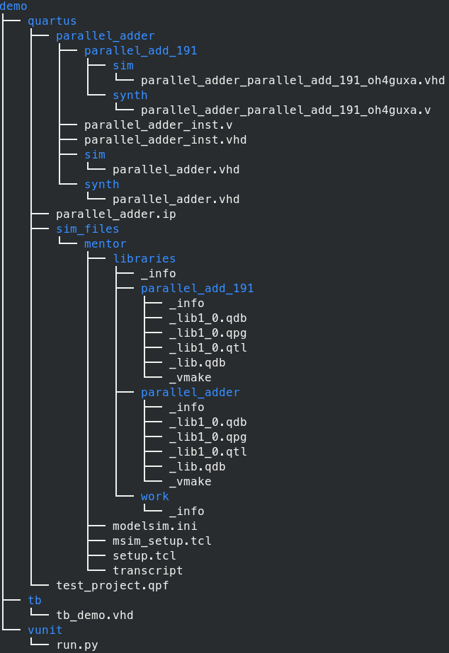
이 토폴로지 뷰 참조해 ROOT 경로와 생성된 라이브러리 경로 지정:
sim_files는 Step 2에서 지정한 디렉토리로 mentor 폴더 저장 위치.
from vunit import VUnit
from os.path import join, dirname, abspath
# ROOT
root = join(dirname(__file__), '../')
# Path to generated libraries
path_2_lib = '/quartus/sim_files/mentor/libraries/'
# ROOTvu라는 VUnit 인스턴스 생성 후 우리 VHDL 코드용 설계 라이브러리 지정하고 외부 라이브러리 링크:
# Create VUnit instance by parsing command line arguments
vu = VUnit.from_argv()
# create design's library
my_lib = vu.add_library('my_lib')
# Link external library
vu.add_external_library("parallel_adder", root + path_2_lib + "parallel_adder")
마지막으로 소스 파일 추가. given_ip_name 디렉토리 하위 세 폴더에 위치:
parallel_add_191synthsimsynth와 sim 디렉토리는 우리 IP의 탑레벨 설계와 같은 정보 포함. 포맷은 Step 1에서 선택한 언어에 따라 VHDL 또는 Verilog.
탑레벨 설계에 서브컴포넌트 포함 시 해당 소스 파일도 포함해야 함. given_ip_name 디렉토리 하위 폴더(예: 우리 경우 parallel_add_191 컴포넌트)에 위치.
my_lib.add_source_files(join(root,'quartus','parallel_adder','sim','parallel_adder.vhd'))
my_lib.add_source_files(join(root,'quartus','parallel_adder','parallel_add_191','sim','parallel_adder_parallel_add_191_oh4guxa.vhd'))
my_lib.add_source_files(join(root,'tb','tb_demo.vhd'))
testbench = my_lib.entity("tb_demo")
vu.main()시작하려면 VUnit 테스트벤치 기초 링크 참조.
우리 테스트벤치로 돌아와 VUnit 라이브러리와 원하는 기타 라이브러리 추가, 신호 정의.
주의: 예제에서 프로세스 실행은 순차적. 제어 신호(플래그)로 프로세스 시작/종료 알림.
library IEEE; use IEEE.std_logic_1164.all; use ieee.numeric_std.all;
library vunit_lib; context vunit_lib.vunit_context;
entity tb_demo is generic ( runner_cfg : string:= runner_cfg_default); end tb_demo;
architecture sim of tb_demo is
constant clk_period : time := 10 ns;
signal clk : std_logic := '0';
signal rst : std_logic := '0';
-- INPUTS
signal data_a : std_logic_vector(0 to 15):= (others => '0');
signal data_b : std_logic_vector(0 to 15):= (others => '0');
signal data_c : std_logic_vector(0 to 15):= (others => '0');
-- OUTPUTS
signal result : std_logic_vector(0 to 16);
-- CONTROL FLAGS
signal reset_done :boolean := false;
signal sim_done :boolean := false;
signal start_sim :boolean := false;
UUT 인스턴스화. Quartus가 ip_name_inst.vhd, ip_name_inst.v 파일명 규칙으로 VHDL/Verilog 컴포넌트 인스턴스화 예제 제공.
begin
-- Unit Under Test
UUT : entity work.parallel_adder port map (
data0x => data_a, -- parallel_add_input.data0x
data1x => data_b, -- .data1x
data2x => data_c, -- .data2x
result => result -- parallel_add_output.result
);
처음 시작하는 두 프로세스는 clk_process와 reset_rel. 후자는 리셋 후 reset_done 플래그를 true로 드라이브하고 일시정지, 전자는 시뮬레이션 시간 내내 동작.
clk_process : process begin
clk <= '1'; wait for clk_period/2;
clk <= '0'; wait for clk_period/2;
end process clk_process;

reset_rel : process begin
rst <= '1'; wait for clk_period*2;
wait until rising_edge(clk);
rst <= not rst; reset_done <= true; wait;
end process reset_rel;
리셋 완료로 test_runner 프로세스 호출해 테스트 실행. 테스트 러너는 sim_done 플래그가 true로 드라이브될 때까지 활성(마지막 프로세스에서 발생).
test_runner : process begin
test_runner_setup(runner, runner_cfg);
wait until reset_done and rising_edge(clk);
iterate : while test_suite loop
start_sim <= true;
if run("test_case_1") then
info ("Start");
info (running_test_case);
wait until sim_done;
end if;
end loop;
test_runner_cleanup(runner);
end process test_runner;
마지막으로 data_generator 프로세스가 for 루프로 병렬 가산기 세 입력에 값 할당하며 여러 덧셈 실행.
주의: 이 프로세스는 test_runner가 start_sim 플래그 설정으로 지시할 때 트리거. 끝에서 sim_done 플래그 올려 테스트 러너가 시뮬레이션 일시정지 명령.
data_generator : process
constant tag2 : log_level_t := new_log_level("INFO", fg => blue, bg => black, style => bright);
variable a,b,c,d : integer;
begin
wait until start_sim;
wait until rising_edge(clk);
show(display_handler, tag2);
if running_test_case = "test_case_1" then
for i in 0 to 10 loop
data_a <= std_logic_vector(to_unsigned(i+10,data_a'length));
data_b <= std_logic_vector(to_unsigned(i+20,data_a'length));
data_c <= std_logic_vector(to_unsigned(i+30,data_a'length));
wait until rising_edge(clk);
a := to_integer(unsigned(data_a));
b := to_integer(unsigned(data_b));
c := to_integer(unsigned(data_c));
d := to_integer(unsigned(result));
log( integer'image(a) &" + "& integer'image(b) &" + "& integer'image(c) &" = "& integer'image(d), tag2);
end loop;
end if;
sim_done <= true;
end process data_generator; 테스트 케이스 실행과 예상대로 작동 확인 위해 run.py 스크립트 디렉토리에서 터미널에 다음 명령 실행.
python ./run.py -v주의: 커스텀 로거로 verbose -v 옵션 제공 시 출력에서 더 잘 보임. 단일 테스트 케이스만 정의돼 별도 옵션 불필요.
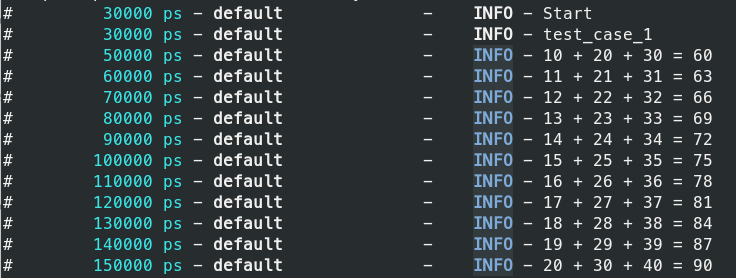
ModelSim에서 결과 검증하려면 다음 명령:
python ./run.py --gui
(이미지 클릭 시 확대)
요약하면, IP 카탈로그에 있는 Quartus IP를 VUnit 환경에서 통합하고 테스트하는 방법을 배웠습니다. 이 튜토리얼은 사전 정의된 IP를 사용했지만, 같은 과정이 커스텀 패키지 IP에도 적용됩니다.
아직 안 보셨다면 이 VUnit 튜토리얼 확인:
Getting started with VUnit
VHDL
이전 for 루프 탐구에 이어, 이 튜토리얼은 while 루프를 다룹니다. while 루프는 미리 정해진 범위가 아닌 동적 조건에 따라 반복을 제어할 수 있는 강력한 구조입니다. while 루프는 지정된 조건이 true로 유지되는 동안 본문을 반복 실행합니다. 이는 반복 횟수가 런타임 데이터나 복잡한 로직에 의존하는 시나리오에 이상적입니다. 이 게시물은 기본 VHDL 튜토리얼 시리즈의 일부입니다. 구문 while <조건> loop -- 루프 본문 end loop; <조건>은 부울 값으로 평가되어야 합니다. 단순
이전 튜토리얼에서는 loop 문을 사용한 무한 루프 생성과 exit로 빠져나오는 방법을 탐구했습니다. 루프를 특정 횟수만큼 실행해야 한다면? For-루프가 가장 직관적인 해결책입니다. For-루프는 정수 또는 열거형 항목의 고정 범위를 순회합니다. 현재 반복 값은 암시적으로 선언된 상수를 통해 루프 내부에서 자동으로 사용 가능합니다. 이 기사는 기본 VHDL 튜토리얼 시리즈의 일부입니다. 구문 for <상수> in <범위> loop -- 루프 본문 end loop; 여기서 <상수>는 루프 카운터의 사